1
Unit / Module Description:
FPGA-only module SDK
Unit / Module Number:
SMT1026
Document Issue Number:
Issue Date:
Original Author:
Emilie Wheatley
User Manual
for
SMT1026
Sundance Multiprocessor Technology Ltd, Chiltern House,
Waterside, Chesham, Bucks. HP5 1PS.
This document is the property of Sundance and may not be copied
nor communicated to a third party without prior written
permission.
© Sundance Multiprocessor Technology Limited 2009
Revision History
Issue
Changes Made
Date
Initials
Table of Contents
1
Introduction ........................................................................................................................ 4
1.1 SMT1026 main features ............................................................................................... 4
1.2 Supported Hardware..................................................................................................... 5
2
Getting started ................................................................................................................... 5
2.1 Abbreviations ................................................................................................................. 6
2.2 Prerequisites ................................................................................................................... 6
2.3 Software Installation ..................................................................................................... 6
2.3.1 Software Installation From CD .............................................................................. 6
2.3.2 Visual Studio Configuration ................................................................................... 6
2.3.3 Visual Studio express 2010 Configuration ......................................................... 7
3
Software ............................................................................................................................... 8
3.1 Interface Mechanism ..................................................................................................... 8
3.2 Functions exported by SmtFPGA.dll ......................................................................... 9
3.3 Sundance Hardware Interface Description ............................................................ 14
3.3.1 General interface .................................................................................................... 15
3.3.2 SMT350 interface .................................................................................................... 21
3.3.3 SMT351 interface .................................................................................................... 24
3.3.4 SMT381 interface .................................................................................................... 25
3.3.5 SMT384 interface .................................................................................................... 27
3.3.6 SMT391 interface .................................................................................................... 29
3.3.7 SMT941 interface .................................................................................................... 34
4
Utilities ............................................................................................................................... 37
4.1 Configure FPGA-only modules ................................................................................. 37
4.1.1 SMT350 ..................................................................................................................... 38
4.1.2 SMT351 ..................................................................................................................... 40
4.1.3 SMT381 ..................................................................................................................... 41
4.1.4 SMT384 ..................................................................................................................... 43
4.1.5 SMT391 ..................................................................................................................... 44
5
Examples ............................................................................................................................ 46
5.1 Firmware ........................................................................................................................ 46
5.2 Host ................................................................................................................................ 47
5.3 Output ............................................................................................................................ 48
1 Introduction
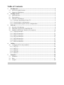
This section gives a brief description of the SMT1026 package.
The SMT1026 is a SDK for Windows.
The SMT1026 is an efficient, ready to use, host side interface to Sundance FPGA-only
module. It allows you to control the FPGA-only modules from the host as well as to
exchange data between the host and the module on the first site of the Sundance carrier
board.
The figure above shows the SMT1026 forming the link between your application and the
Sundance hardware in your system. The SMT1026 hides the details of the device driver,
allowing you to concentrate on the development process.
1.1 SMT1026 main features
This section lists the main characteristics of the SMT1026 package.
The SMT1026 SDK:
•
•
•
•
•
•
Accelerate your development time by providing ready-to-use library of functions.
Configure the FPGA from the Host.
Transfer data from the FPGA-only module to the Host.
Control the data acquisition on the daughter modules from the Host.
Give you a basic framework for more complex custom systems.
Provide you with C++ type interfaces to the FPGA-only modules.
1.2 Supported Hardware
The SMT1026 currently supports the following carrier boards:
Carrier board
SMT100
SMT101
SMT105
Description
SLB carrier, Virtex 5, 512Mbytes DDR2,
USB2, RS232, MicroSD/Transflash, 4lane and 1-lane PCIe interface, 32-bit
33MHz PCI, cable PCIe connector
SLB carrier, Virtex 5, 512Mbytes DDR2,
USB2, RS232, MicroSD/Transflash, 4lane and 1-lane PCIe interface, 8 channel
12-bit ADC, 32-bit 33 MHz PCI
SLB carrier, Virtex 5, 512Mbytes DDR2,
USB2, RS232, MicroSD/Transflash, 4lane and 1-lane PCIe interface, 3 banks
of QDRII memory 72 Mbit, 2x Fibre
modules
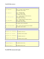
The SMT1026 currently supports the following FPGA-only module:
Carrier board
SMT350
SMT351
SMT370
Description
Dual ADC/DAC module at 500MSPS
1GB memory module
Dual channel ADC/DAC
SMT381
Dual 14-bit DAC module at 1GSPS
SMT384
SMT390
SMT391
SMT941
Quad 14-bit ADC module at 125MSPS
Dual 12-bit ADC module at 210MSPs
Dual 8-bit ADC module at 1GSPS
4 channel 14-bit ADC at 250 MHz
2 Getting started
This section will help you to get started:
•
•
•
Abbreviations
Prerequisites
Software Installation
Functionality
Full support
Full support
Full support
2.1 Abbreviations
The following abbreviations will be used through the all document:
FPGA
CPLD
PCI
PLD
SMT
TIM
Field-Programmable Gate Array
Complex PLDs
Peripheral Component Interconnect
Programmable Logic Device
Sundance Multiprocessor Technology Ltd.
Texas Instruments Module
2.2 Prerequisites
The language C++ is used for the software interfaces. Even if you are not familiar with
C++, you should be able to find your way by referring to the samples. The samples have
been compiled and tested with Microsoft Visual Studio 2010, express edition.
2.3 Software Installation
This section describes how to install the SMT1026 package.
•
•
•
From CD
Visual Studio Configuration
Visual Studio 2010 Configuration
2.3.1 Software Installation From CD
Insert the SMT1026 CD into your CD drive. The setup program should start
automatically; if it doesn’t you can start it yourself by opening an Explorer window,
browsing to the CD, and then double-clicking setup.exe. The installation program will
give you the option of installing samples. We recommend that you become familiar with
the SMT1026 by installing and reviewing the sample code.
The default directory is “C:\Program Files\Sundance\SMT1026”.
The applications need access to smtFPGA.h and smtFPGA.lib. You need to arrange that
these files can be found during compilation and linking. We strongly recommend that you
do not make copies of these files, but access them from the installation directory. See
the Visual Studio Configuration for more details.
2.3.2 Visual Studio Configuration
The installation process configures the examples to compile and link correctly without
any user intervention. However, for your own applications, you need to configure visual
studio to add the paths to the include and lib directories to your compiler options.
You do this as follows:
•
•
•
•
•
•
•
2.3.3
Open Visual studio.
Select "Tools->Options" from the menu.
Select the “Directories” tab.
Select “Include files” from the "Show directories for" drop down list.
Add the path to the include directory for the SMT1026 installation to the list of
directories.
Select “Library files” from the "Show directories for" drop down list.
Add the path to the library files for the SMT1026 to the to the list of directories.
Visual Studio express 2010 Configuration
The installation process configures the examples to compile and link correctly without
any user intervention. However, for your own applications, you need to configure visual
studio to add the paths to the include and lib directories to your compiler options.
You do this as follows:
•
•
•
•
•
•
•
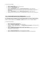
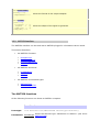
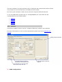
Open Visual studio express 2010.
Select "Project->Properties" from the menu.
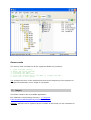
Select the “VC++ Directories” in “Configuration properties” on the left of the
window.
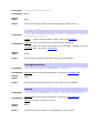
Select “Include directories” on the right of the window.
Add the path to the include directory for the SMT1026 installation to the list of
directories, as shown below.
Select “Library directories” on the right of the window.
Add the path to the library files for the SMT1026 to the list of directories.
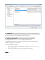
3 Software
This section describes the functionality of the SMT1026 package.
3.1 Interface Mechanism
The design makes use of a C++ style interface pointer to the hardware.
SmtFPGA.dll exports functions that gather information about the installed boards and
provide an interface pointer for later use.
To use the SMT1026, you need to:
•
Obtain an interface pointer to the hardware by calling
SmtxxxOpen(unsigned
int nIndex = 0).
•
Use the interface pointer to call functions related to the hardware.
Example:
// Open the SMT391 library
IFSmt391 *pSmt391 = Smt391Open(0);
pSmt391->ResetTIMs();
// Configure the FPGA
pSmt391->ConfigureFPGA(BITSTREAM, QUICK_CONF);
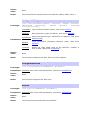
3.2 Functions exported by SmtFPGA.dll
This section describes each of the functions exported by SmtFPGA.dll. These functions
are described in the header file IFSmtFPGA.h.
•
•
•
•
•
•
•
•
•
•
•
•
•
•
•
•
SmtFPGAOpen
SmtFPGAClose
Smt350Open
Smt350Close
Smt351Open
Smt351Close
Smt370Open
Smt370Close
Smt384Open
Smt384Close
Smt390Open
Smt390Close
Smt391Open
Smt391Close
Smt941Open
Smt941Close
The following functions can be used to get information about the carrier board.
•
•
•
•
SmtGetBoardCount
SmtGetBoardIndex
SmtGetBoardInfo
SmtGetError
Functions to access the interfaces
SmtFPGAOpen
Prototype:
IFSmtFPGA * SmtFPGAOpen(unsigned int nIndex=0);
Parameters: nIndex
Return
value:
Index of the carrier board on which the FPGA-only module is
plugged in.
The return value is a pointer to an FPGA-only module interface.
Notes:
This function obtains an interface to any FPGA-only module plugged in the
first TIM site of a Sundance carrier board.
SmtFPGAClose
Prototype:
void SmtFPGAClose(IFSmtFPGA *p);
Parameters: p
Pointer to the FPGA-only module interface.
Return
value:
None.
Notes:
This function closes the FPGA-only module interface.
Smt350Open
Prototype:
IFSmt350 * Smt350Open(unsigned int nIndex=0);
Parameters: nIndex Index of the carrier board on which theSmt350 is plugged in.
Return
value:
The return value is a pointer to an Smt350 interface.
Notes:
This function obtains an interface to an Smt350 plugged in the first TIM
site of a Sundance carrier board.
Smt350Close
Prototype:
void Smt350Close(IFSmt350 *p);
Parameters: p
Pointer to theSmt350 interface.
Return
value:
None.
Notes:
This function closes the Smt350 interface.
Smt351Open
Prototype:
IFSmt351 * Smt351Open(unsigned int nIndex=0);
Parameters: nIndex Index of the carrier board on which the Smt351 is plugged in.
Return
value:
The return value is a pointer to an Smt351 interface.
Notes:
This function obtains an interface to an Smt351 plugged in the first TIM
site of a Sundance carrier board.
Smt351Close
Prototype:
void Smt351Close(IFSmt351 *p);
Parameters: p
Pointer to the Smt351 interface.
Return
value:
None.
Notes:
This function closes the Smt351 interface.
Smt370Open
Prototype:
IFSmt370 * Smt370Open(unsigned int nIndex=0);
Parameters: nIndex Index of the carrier board on which the Smt370 is plugged in.
Return
value:
The return value is a pointer to an Smt370 interface.
Notes:
This function obtains an interface to an Smt370 plugged in the first TIM
site of a Sundance carrier board.
Smt370Close
Prototype:
void Smt370Close(IFSmt370 *p);
Parameters: p
Pointer to the Smt370 interface.
Return
value:
None.
Notes:
This function closes the Smt370 interface.
Smt384Open
Prototype:
IFSmt384 * Smt384Open(unsigned int nIndex=0);
Parameters: nIndex Index of the carrier board on which the Smt384 is plugged in.
Return
value:
The return value is a pointer to an Smt384 interface.
Notes:
This function obtains an interface to an Smt384 plugged in the first TIM
site of a Sundance carrier board.
Smt384Close
Prototype:
void Smt384Close(IFSmt384 *p);
Parameters: p
Pointer to the Smt384 interface.
Return
value:
None.
Notes:
This function closes the Smt384 interface.
Smt390Open
Prototype:
IFSmt390 * Smt390Open(unsigned int nIndex=0);
Parameters: nIndex Index of the carrier board on which the Smt390 is plugged in.
Return
value:
The return value is a pointer to an Smt390 interface.
Notes:
This function obtains an interface to an Smt390 plugged in the first TIM
site of a Sundance carrier board.
Smt390Close
Prototype:
void Smt390Close(IFSmt390 *p);
Parameters: p
Pointer to the Smt390 interface.
Return
value:
None.
Notes:
This function closes the Smt390 interface.
Smt391Open
Prototype:
IFSmt391 * Smt391Open(unsigned int nIndex=0);
Parameters: nIndex Index of the carrier board on which the Smt391 is plugged in.
Return
value:
The return value is a pointer to an Smt391 interface.
Notes:
This function obtains an interface to an Smt391 plugged in the first TIM
site of a Sundance carrier board.
Smt391Close
Prototype:
void Smt350Close(IFSmt391 *p);
Parameters: p
Return
value:
Pointer to the Smt391 interface.
None.
Notes:
This function closes the Smt391 interface.
Smt941Open
Prototype:
IFSmt941 * Smt941Open(unsigned int nIndex=0);
Parameters: nIndex Index of the carrier board on which the Smt941 is plugged in.
Return
value:
The return value is a pointer to an Smt941 interface.
Notes:
This function obtains an interface to an Smt941 plugged in the first TIM
site of a Sundance carrier board.
Smt941Close
Prototype:
void Smt941Close(IFSmt941 *p);
Parameters: p
Pointer to the Smt941 interface.
Return
value:
None.
Notes:
This function closes the Smt941 interface.
Functions to get information about the carrier board
SmtGetBoardCount
Prototype:
DWORD SmtGetBoardCount(void);
Parameters: None.
Return
value:
The return value is the number of carrier board found.
Notes:
This function returns the number of Sundance carrier boards found in the
system.
SmtGetBoardIndex
Prototype:
INT SmtGetBoardIndex(UINT nBaseAddress);
Parameters: nBaseAddress Base address of the board to open.
Return
The return value is the board index.
value:
Notes:
This function returns an index to the board at the base address
nBaseAddress. If no board is found, the function returns -1.
SmtGetBoardInfo
Prototype:
SMTRet SmtGetBoardInfo(UINT nIndex, SMTBI& info);
nIndex Index of the board to return information about.
Parameters:
info
The information structure to populate.
Return
value:
The return value is the board index.
Notes:
This function returns information about the carrier board specified by
nIndex.
SmtGetError
Prototype:
const char * SmtGetError(SMTRet Error);
Parameters: Error Error value to translate into a string.
Return
value:
The return value is an error string.
Notes:
This function returns a string description of the error specified by Error.
3.3 Sundance Hardware Interface Description
Once an interface to the hardware has been obtained by calling
SmtXXXOpen(unsigned int nIndex=0), the interface allows you to access the
FPGA-only module functions.
•
•
•
•
•
•
•
•
•
General interface
Smt350 interface
Smt370 interface
Smt351 interface
Smt381 interface
Smt384 interface
Smt390 interface
Smt391 interface
Smt941 interface
3.3.1 General interface
The general interface can be used with any FPGA-only module plugged in a Sundance
carrier board.
This section describes:
the general functions
•
•
•
•
•
•
•
•
•
•
•
•
•
ConfigureFPGA
HostRead
HostWrite
HostCancel
WriteCtrlWord
StoreDataToFile
CallbackSet
CallbackGet
ResetTIMs
ResetBoard
GenSig
SetTimeout
GetTimeout
the general structures
•
•
•
TEMP
SN
FILE_OPTIONS
the general enumerated types
•
•
•
•
•
CHSEL
OUTPUT
VCXOTYPE
HOST_LINK
DATAFORMAT
The general functions
All the following functions can throw an SMTExc exception.
ConfigureFPGA
Prototype:
void
ConfigureFPGA(const
bQuickConf=false);
char
*pBitstream,
bool
pBitstream FPGA bitstream
Parameters:
True: Reset the FPGA. The FPGA has to be fully configured at
bQuickConf least once before using this option.
False: Configure fully the FPGA. (default)
Return
value:
None.
Notes:
This function configures the FPGA of the FPGA-only module plugged in the
first TIM slot of the Sundance carrier board.
HostRead
Prototype:
Parameters:
void HostRead(void *pBuf, unsigned int nBytes, HOST_LINK
hostlink=cp);
pBuf
Buffer that receives the data.
nBytes
Size of the data to read.
hostlink
Communication link on which to read the data. Host comport per
default. (See struct HOST_LINK).
Return
value:
None.
Notes:
This function reads data from the carrier board.
HostWrite
Prototype:
Parameters:
void HostWrite(void *pBuf, unsigned int nBytes, HOST_LINK
hostlink=cp);
pBuf
Buffer that contains the data to write.
nBytes
Size of the data to write.
hostlink
Communication link on which to write the data. Host comport per
default. (See enum HOST_LINK).
Return
value:
None.
Notes:
This function writes data to the carrier board.
HostCancel
Prototype:
void HostCancel(HOST_LINK hostlink=cp);
Parameters: hostlink
Communication link on which to write the data. Host comport per
default. (See enum HOST_LINK).
Return
value:
None.
Notes:
This function cancels pending read/write operations.
WriteCtrlWord
Prototype:
void WriteCtrlWord(unsigned int nCtrl);
Parameters: nCtrl
Control word to send.
Return
value:
None.
Notes:
This function sends a control word to the FPGA-only module on the first
TIM slot of a Sundance carrier board.
StoreDataToFile
Prototype:
void StoreDataToFile(const char *pcFile, void *pBuf,
unsigned int nBytes, unsigned int nNoOfBit, FILE_OPTIONS
*=0);
pcFile
Name of the file where the data will be saved.
pBuf
Buffer containing the data.
nBytes
Size of the data.
nNoOfBit
Number of relevant bits per word. This value is used to mask
each word saved in the file.
pFileOpt
Structure which contains the extra file options (append data,
add date and time). (See struct FILE_OPTIONS).
Parameters:
Return
value:
None.
Notes:
This function stores data into a file.
CallbackSet
Prototype:
void CallbackSet(SMTFPGACALLBACK pf, void *user);
pf
Callback function.
user
User specified callback value.
Parameters:
Return
value:
None.
Notes:
This function sets the function that is to be called when words are sent to
the FPGA module.
CallbackGet
Prototype:
void CallbackGet(SMTFPGACALLBACK pf, void *user);
pf
Callback function.
user
User specified callback value.
Parameters:
Return
value:
None.
Notes:
This function gets the function that is to be called when words are sent to
the FPGA module.
ResetTIMs
Prototype:
void ResetTIMs(void);
Parameters: None.
Return
value:
None.
Notes:
This function resets the TIMs on the carrier board.
ResetBoard
Prototype:
void ResetBoard(void);
Parameters: None.
Return
value:
None.
Notes:
This function resets the carrier board.
GenSig
Prototype:
void GenSig(SIGGEN type, int nAmp, float fSamplingFreq,
float fSigFreq, unsigned int *pBuf, int nBytes);
type
Type of signal to generate (See SIGGEN).
nAmp
Signal amplitude.
fSamplingFreq Sampling frequency.
Parameters:
Return
value:
fSigFreq
Signal frequency.
pBuf
Buffer for the signal data.
nBytes
Size of the buffer in bytes.
None.
Notes:
This function generates a signal.
SetTimeout
Prototype:
void SetTimeout(unsigned int n);
Parameters: n
Value of the timeout in ms. If 0 the timeout is not set and the
comport and RSL functions will never return if they fail.
Return
value:
None.
Notes:
This function changes the value of the timeout for the comport and RSL
functions. Unless really necessary the user is not advised to use this
function.
GetTimeout
Prototype:
unsigned int GetTimeout(void);
Parameters: None.
Return
value:
The current value of the timeout.
Notes:
This function returns the current value of the timeout for the comport and
RSL functions.
The general structures
struct TEMP
unsigned int nAir
Temperature measured on the base module such as an
SMT338VP.
unsigned int nFPGA
Temperature measured on the FPGA of the base module.
unsigned
nDaughter_Air
int
unsigned
nDaughter_ADC
int Temperature measured on the ADCs of the daughter
Temperature measured on the daughter module.
module.
struct SN
unsigned int nNoA
Serial number A of the base module.
unsigned int nNoB
Serial number B of the base module.
unsigned int nNoC
Serial number C of the base module.
unsigned int nNoD
Serial number D of the base module.
unsigned int nDaughterNoA Serial number A of the daughter module.
unsigned int nDaughterNoB Serial number B of the daughter module.
unsigned int nDaughterNoC Serial number C of the daughter module.
unsigned int nDaughterNoD Serial number D of the daughter module.
struct FILE_OPTIONS
True = append data at the end of the file.
bool bAppend
False = overwrite the file.
The default value is false.
True = add date and time before writing the data.
bool bDateStamp
False = don’t add the date and time inside the file.
The default value is false.
The general enumerated types
Enumerated types
Description
enum CHSEL {
channela = 1,
channelb = 2,
channelab= 3
};
Selects the active channel.
enum OUTPUT {
normal = 0,
zeros = 1,
ones
= 2,
test
= 3
};
Selects the type of the output samples.
enum VCXOTYPE {
vcxo100 = 0,
vcxo245 = 1
};
Selects the VCXO installed on the FPGA module: 100Mhz or
245.76 MHz
enum HOST_LINK {
cp = 0,
rsl = 1
};
The host application can always communicate with the Sundance
carrier boards through the host comport. But some carrier board
offers other communication link like the RSL link. This
enumerated type selects the host link used to communicate with
the Sundance carrier board.
enum DATAFORMAT {
binary = 0,
Selects the format of the output samples.
complement2 = 1
};
enum SIGGEN {
sine = 0,
triangle =
square
=
ramp_pos =
ramp_neg = 4
};
1,
2, Selects the shape of the signal to generate.
3,
3.3.2 SMT350 interface
The SMT350 interface can be used with a SMT350 plugged in a Sundance carrier board.
This section describes:
the SMT350 functions
•
•
•
•
ResetDevices
ConfigureADCReg
ConfigureADCClock
Acquire
the SMT350 structures
•
•
•
CLKMODE350
SETDAC
SETCLK
the SMT350 enumerated types
•
•
SMT350TYPE
SAMPLING_RATIO
The SMT350 functions
All the following functions can throw an SMTExc exception.
ResetDevices
Prototype:
void ResetDevices(SMT350TYPE smt350type=cdcm7005);
Parameters: smt350type
Select the SMT350 type: CDCM7005 or AD9510. (See enum
SMT350TYPE).
Return
value:
None.
Notes:
This function does a global reset of the SMT350 (ADCs, DACs, Clock…).
ConfigureADCReg
Prototype:
void ConfigureADCReg(OUTPUT outputADC, SETDAC *pSetDAC,
SMT350TYPE
smt350type,
SETCLK
*pSetClk,
VCXOTYPE
vcxotype=vcxo245);
outputADC
Type of data the ADCs output. (See enum OUTPUT).
pSetDAC
DAC parameters (gain and offset). (See struct SETDAC).
smt350type
Select the SMT350 type: CDCM7005 or AD9510. (See enum
SMT350TYPE).
pSetClk
Clock parameters (sampling frequency ratio). (See struct
SETCLK).
vcxotype
Select the right VCXO used on the SMT350: 100MHz or
245.76 MHz. (See enum VCXOTYPE).
Parameters:
Return
value:
None.
Notes:
This function configures the ADC, DAC and clock registers.
ConfigureADCClock
Prototype:
void ConfigureADCClk(CLKMODE350 *pClkMode);
Parameters: pClkMode ADC clock mode parameters. (See struct CLKSMT350).
Return
value:
None.
Notes:
This function configures the ADC clock.
Acquire
Prototype:
void Acquire(CLKMODE350 *pClkMode);
Parameters: pClkMode ADC clock mode parameters. (See struct CLKSMT350).
Return
value:
None.
Notes:
This function acquires data from the Smt350.
The SMT350 sructures
struct CLKMODE350
true = external reference;
bool bExtRef
false = on-board 10 MHz reference.
The default value is false.
true = external clock;
bool bExtClk
false = on-board VCXO.
The default value is false.
true = trigger polarity channel A and B;
bool bTrigInvert
false = Non-inverting.
The default value is false.
true = trigger selection channel A and B;
bool bTrigExt
false = internal trigger.
The default value is false.
Channel selection.
The default value is channelab.
CHSEL ChSel
True = ADC A and B output 2’s complement samples
bool b2sComplement
False = ADC A and B output binary samples.
The default value is false.
struct SETDAC
unsigned int nOffsetA
The default value is 0.
Gain DAC channel A.
The default value is 0xFFF.
unsigned int nGainA
unsigned int nOffsetB
unsigned int nGainB
Offset DAC channel A.
Offset DAC channel B.
The default value is 0.
Gain DAC channel B.
The default value is 0xFFF.
struct SETCLK
SAMPLING_RATIO
ADCSamplingRatio
Sampling frequency divider for the ADCs.
SAMPLING_RATIO
DACSamplingRatio
Sampling frequency divider for the DACs.
The default value is div2.
The default value is div3.
The SMT350 enumerated types
Enumerated type
Description
enum SMT350TYPE
{
There are two types of SMT350. The default one with the
ad9510
= 0, component CDCM7005 and the one with the component AD9510.
cdcm7005 = 1 The right SMT350 type can be selected using this enumerated type.
};
enum
SAMPLING_RATIO
{
div1 = 0,
div2 = 1,
div3 = 2,
div4 = 3,
div6 = 4,
div8 = 5,
div16 = 6
};
This enumerated type selects the sampling frequency divider.
3.3.3 SMT351 interface
The SMT351 interface can be used with a SMT351 plugged a Sundance carrier board.
This section describes:
the SMT351 functions
•
•
•
Acquire
ReadBack
FillMem
The SMT351 functions
All the following functions can throw an SMTExc exception.
Acquire
Prototype:
void Acquire(unsigned int nBytes, unsigned int nAddress);
nBytes
Number of bytes to acquire.
Parameters:
nAddress Memory address from where to acquire the data.
Return
value:
None.
Notes:
This function prepares the SMT351 for the acquisition.
ReadBack
Prototype:
void ReadBack(void);
Parameters: None.
Return
value:
None.
Notes:
This function starts the acquisition from the SMT351.
FillMem
Prototype:
void FillMem(unsigned int *pBuf, unsigned int nBytes);
pBuf
Buffer that contains the data to copy to the SMT351 memory.
Parameters:
nBytes Number of bytes to copy to the SMT351 memory.
Return
value:
None.
Notes:
This function acquires data from the SMT351.
3.3.4 SMT381 interface
The SMT381 interface can be used with a SMT381 plugged a Sundance carrier board.
This section describes:
the SMT381 functions
•
•
•
•
ConfigureDACReg
ConfigureDACClock
SetTrigger
Reset
the SMT381 enumerated types
•
DATAMODE
The SMT381 functions
All the following functions can throw an SMTExc exception.
ConfigureDACReg
Prototype:
void ConfigureDACReg(DATAMODE mode, unsigned short *pBuf,
unsigned int nBurstSize);
mode
Select the data mode (See struct DATAMODE)..
pBuf
Buffer that contains the data to write to the DAC memory
(only used when the direct mode is selected).
Parameters:
Set the burst size for the DACs. Typically it will be the number
nBurstSize of 14-bit samples divided by the number of samples per cycle
(NB_SAMPLE_CYCLE).
Return
value:
None.
Notes:
This function configures the DAC registers of the SMT381.
ConfigureDACClock
Prototype:
unsigned
int
ConfigureADCClock(unsigned
nRf_SamplingFreq, bool bOnBoardClk);
int
nRf_SamplingFreq Sampling frequency of the on-board clock.
Parameters:
bOnBoardClk
True to use the on-board clock otherwise false. False is
the default value.
Return
value:
Sampling frequency of the on-board clock.
Notes:
This function configures the clock of the SMT381.
SetTrigger
Prototype:
void SetTrigger(bool bStart);
Parameters: bStart Set the trigger to 0 of 1. The trigger is active high.
Return
value:
None.
Notes:
This function sets the trigger of the SMT381.
Reset
Prototype:
void Reset(bool bSDB, bool bDAC, bool bDCM);
bSDB
SDB reset. 0 = inactive, 1 = active.
bDAC
DAC reset, active on falling edge. Reset all FPGA internal registers
Parameters:
and DAC.
bDCM
DCM reset. 0 = inactive, 1 = active.
Return
value:
None.
Notes:
This function resets the SMT381.
The SMT381 enumerated types
Enumerated
Description
type
enum
DATAMODE { Selects the data mode:
direct,
direct = the input data comes from the FPGA, memory = the input data
memory
comes from the DAC memory.
};
3.3.5 SMT384 interface
The SMT384 interface can be used with a SMT384 plugged in a Sundance carrier board.
This section describes:
the SMT384 functions
•
•
•
•
ResetDevices
ConfigureADCReg
ConfigureADCClock
Acquire
the SMT384 structures
•
CLKMODE384
The SMT384 functions
All the following functions can throw an SMTExc exception.
ResetDevices
Prototype:
void ResetDevices(void);
Parameters: None.
Return
value:
None.
Notes:
This function does a global reset of the SMT384 (ADCs, Clock…).
ConfigureADCReg
Prototype:
Parameters:
void ConfigureADCReg(OUTPUT output, nVCXOTYPE vcxotype,
unsigned int nClkDiv);
output
Type of data the ADCs output. (See enum OUTPUT).
nClkDiv
VCO clock divider to set the sampling frequency.
vcxotype
Select the right VCXO used on the SMT384: 100MHz or 245.76
MHz. (See enum VCXOTYPE).
Return
value:
None.
Notes:
This function configures the ADC registers of the SMT384.
ConfigureADCClock
Prototype:
void ConfigureADCClk(CLKMODE384 clkmode);
Parameters: clkmode ADC clock mode parameters. (See struct CLKMODE384).
Return
value:
None.
Notes:
This function configures the clock for the ADCs on the SMT384.
Acquire
Prototype:
void Acquire(CLKMODE384 clkmode, unsigned int nBytes);
clkmode ADC clock mode parameters. (See struct CLKMODE384).
Parameters:
nBytes
Number of bytes to acquire.
Return
value:
None.
Notes:
This function set the ADCs on the SMT384 to acquire data.
The SMT384 structures
struct CLKMODE384
true = external reference;
bool bExtRef
false = on-board 10 MHz reference.
The default value is false.
true = external clock;
bool bExtClk
false = on-board VCXO.
The default value is false.
true = trigger polarity channel A and B;
bool bABTrigInvert
false = Non-inverting.
The default value is false.
true = trigger selection channel A and B;
bool bABTrigExt
false = internal trigger.
The default value is false.
true = trigger polarity channel C and D;
bool bCDTrigInvert
false = Non-inverting.
The default value is false.
true = trigger selection channel C and D;
bool bCDTrigExt
false = internal trigger.
The default value is false.
CHSEL ABChSel
Channel A and B selection.
The default value is channelab.
CHSEL CDChSel
Channel C and D selection.
The default value is channelab.
True = ADC A and B output 2’s complement samples
bool bAB2sComplement
False = ADC A and B output binary samples.
The default value is false.
True = ADC C and D output 2’s complement samples
bool bCD2sComplement
False = ADC C and D output binary samples.
The default value is false.
3.3.6 SMT391 interface
The SMT391 interface can be used with a SMT391 plugged in a Sundance carrier board.
This section describes:
the SMT391 functions
•
•
Reset
ConfigureADCReg
•
•
•
•
•
•
•
•
ConfigureADCClock
Acquire
ADCReset
SetADCMode
SetClkMode
GetFirmwareVersion
GetTemp
GetSN
the SMT391 structures
•
SETADC391
the SMT391 enumerated types
•
CLKMODE391
The SMT391 functions
All the following functions can throw an SMTExc exception.
Reset
Prototype:
void Reset(bool bGlobal, bool bADC, bool bUser);
bGlobal True to do a global reset otherwise false.
Parameters: bADC
bUser
True to do an ADC reset otherwise false.
True to do a user reset otherwise false.
Return
value:
None.
Notes:
This function reset the SMT391.
ConfigureADCReg
Prototype:
void
ConfigureADCReg(unsigned
SETADC391 setadc);
int
&nSamplingFreq,
nSamplingFreq Sampling frequency of the on-board clock.
Parameters:
setadc
ADC parameters. (See struct SETADC391).
Return
value:
None.
Notes:
This function configures the ADC registers of the SMT391.
ConfigureADCClock
Prototype:
unsigned
int
ConfigureADCClock(unsigned
nRf_SamplingFreq, bool bOnBoardClk);
int
nRf_SamplingFreq Sampling frequency of the on-board clock.
Parameters:
bOnBoardClk
True to use the on-board clock otherwise false. False is
the default value.
Return
value:
Sampling frequency of the on-board clock.
Notes:
This function configures the clock of the SMT391.
Acquire
Prototype:
Parameters:
void Acquire(unsigned int nBytes=0, bool bDDR=false);
Number of bytes to acquire. If no DDR memory has been
nBytes implemented in the FPGA firmware, the acquisition is continue and
nBytes is not used. 0 is the default value.
bDDR
True when DDR memory is implemented in the FPGA firmware
otherwise false. False is the default value.
Return
value:
None.
Notes:
This function configures the SMT391 to start acquiring data.
StopAcquire
Prototype:
void StopAcquire(HOST_LINK hostlink);
Parameters: hostlink
Communication link on which to write the data. Host comport per
default. (See enum HOST_LINK).
Return
value:
None.
Notes:
This function stops the ADC to acquire data.
ADCReset
Prototype:
void ADCReset(void);
Parameters: None.
Return
value:
None.
Notes:
This function resets the ADCs.
SetADCMode
Prototype:
void SetADCMode(unsigned int n);
Parameters: n
ADC mode value.
Return
value:
None.
Notes:
This function sets the ADC mode.
SetClkMode
Prototype:
void SetClkMode(CLKMODE391 clkmode);
Parameters: clkmode ADC clock mode parameters. (See struct CLKSMT391).
Return
value:
None.
Notes:
This function sets the clock mode.
GetFirmwareVersion
Prototype:
unsigned int GetFirmwareVersion(void);
Parameters: None.
Return
value:
None.
Notes:
This function gets the firmware version. Before using this function the
user has to make sure this functionality is part of the firmware used to
program the FPGA.
GetTemp
Prototype:
void GetTemp(TEMP *pTemp);
Parameters: pTemp
Structure that receives the modules’ temperatures (See struct
TEMP).
Return
value:
None.
Notes:
This function gets the temperatures on different part of the hardware.
Before using this function the user has to make sure this functionality is
part of the firmware used to program the FPGA.
GetSN
Prototype:
void GetSN(SN *pSN);
Parameters: pSN
Structure that receives the modules’ temperatures. (See struct
SN).
Return
value:
None.
Notes:
This function gets the FPGA module serial number. Before using this
function the user has to make sure this functionality is part of the
firmware used to program the FPGA.
The SMT391 structures
struct SETADC391
True = The input for the channels I and Q is the same.
bool bItoQ
False = Channels I and Q have different inputs.
The default value is true.
unsigned int nAnalogGain Analog gain.
The default value is 128.
unsigned int nOffsetComp Offset compensation.
The default value is 0.
True = the ADCs outputs test data.
bool bTest
False = the ADCs outputs data from theirs inputs.
The default value is false.
unsigned int nDrda
Set the value of the DRDA between 0 and 7.
The default value is 7.
The SMT391 enumerated types
Enumerated type
Description
enum CLKMODE391 {
clk_mode_I_I_Q_Q,
clk_mode_Q_I_Q_Q,
Selects the clock mode.
clk_mode_I_I_I_Q,
clk_mode_Q_I_I_Q
};
3.3.7 SMT941 interface
The SMT941 interface can be used with a SMT941 plugged in a Sundance carrier board.
This section describes:
the SMT941 functions
•
•
•
•
•
•
ResetDevices
ConfigureADCReg
AcquireAB
AcquireCD
GetFirmwareVersion
GetError
the SMT941 structures
•
CLKMODE941
the SMT941 enumerated types
•
•
ERRORS
CLOCK_DIVIDER
The SMT941 functions
All the following functions can throw an SMTExc exception.
ResetDevices
Prototype:
void ResetDevices(void);
Parameters: None.
Return
value:
None.
Notes:
This function reset the SMT941.
ConfigureADCReg
Prototype:
int ConfigureADCReg(OUTPUT output, CLKMODE941 clkmode);
output
Type of data the ADCs output. (See enum OUTPUT).
Parameters:
clkmode Select the clock parameters. (See struct CLKMODE941).
Return
value:
None.
Notes:
This function configures the ADC registers of the SMT941.
AcquireAB
Prototype:
int AcquireAB(unsigned
unsigned short *b);
int
nBytes,
unsigned
chart
*a,
nBytes Number of bytes to acquire.
Parameters: a
Data sampled from channel A.
b
Data sampled from channel B.
Return
value:
Return 0 if successful otherwise 1.
Notes:
This function acquires data on channel A and channel B of the SMT941.
AcquireCD
Prototype:
int AcquireCD(unsigned
unsigned short *d);
int
nBytes,
unsigned
chart
*c,
nBytes Number of bytes to acquire.
Parameters: c
Data sampled from channel C.
d
Data sampled from channel D.
Return
value:
Return 0 if successful otherwise 1.
Notes:
This function acquires data on channel C and channel D of the SMT941.
GetFirmwareVersion
Prototype:
unsigned int GetFirmwareVersion(void);
Parameters: None.
Return
value:
None.
Notes:
This function gets the firmware version. Before using this function the
user has to make sure this functionality is part of the firmware used to
program the FPGA.
GetError
Prototype:
char * GetError(int err);
Parameters: err
Error code.
Return
value:
The description of the error code.
Notes:
This function returns the description of the error code enter as parameter.
The SMT941 structures
struct CLKMODE941
True = External reference.
bool bExtRef
False = On-board 10 MHz reference.
The default value is false.
True = External Clock.
bool bExtClk
False = On-board VCXO.
The default value is false.
Trigger polarity
bool bTrigInvert
True = Inverting.
False = Non-Inverting.
The default value is false.
Trigger selection
bool bTrigExt
True = External trigger.
False = Internal trigger.
The default value is false.
True = External reference.
bool b2sComplement
False = On-board 10 MHz reference.
The default value is false.
unsigned int nClkDiv
Set the value of the clock divider.
The default value is div_by_one.
The SMT941 enumerated types
Enumerated type
Description
enum ERRORS {
Error codes.
ERR_SUCCESS = 0,
ERR_CLK_REG = 1,
ERR_CLK_LOCKED = 2,
ERR_ADCAB_DCM_LOCKED = 3,
ERR_ADCCD_DCM_LOCKED = 4
};
enum CLOCK_DIVIDER {
div_by_one
= 0,
div_by_two
= 1,
div_by_three = 2,
div_by_four = 3,
div_by_five = 4
};
Selects the clock divider.
4 Utilities
The utilities are useful little applications.
The following utilities are available with the SMT1026:
•
ConfigFPGAMod
4.1 Configure FPGA7only modules
This application is installed in the following directory: "C:/Program
Files/Sundance/SMT6026/ConfigFPGAMod.exe".
This user interface is a quick and easy way to configure and communicate with an FPGAonly module on the first TIM site of a Sundance carrier board.
It's also a good example of what can be achieved using the SMT1026 libraries.
To run the application, double-click on "ConfigFPGAMod.exe" and select the tab
corresponding to your FPGA-module:
•
•
•
•
•
SMT350
SMT351
SMT381
SMT384
SMT391
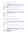
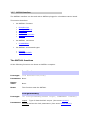
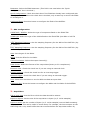
4.1.1 SMT350
This section explains how to use the "Configure FPGA-only module" user interface.
For more information on how to set the parameters please look at the SMT350 user
manual.
1 - FPGA Configuration:
Bitstream: Select the FPGA bitstream. (This field is not used when the "Quick
Configuration" box is checked.)
Quick Configuration: Check this check box if the FPGA has already been configured with
the right bitstream. When this check box is checked, only a start key is sent to the FPGA
to reconfigure it.
Configure FPGA: Press this button to configure the FPGA of the SMT391.
2 - ADC Configuration:
CDCM7005 / AD9510: Select the type of component fitted on the FPGA TIM.
VCXO type: Select the type of the VCXO fitted on the FPGA TIM (100 MHz or 245.76
MHz).
ADC Sampling Frequency: Set the sampling frequency for the ADCs of the SMT350. (Up
to 125MHz).
DAC Sampling Frequency: Set the sampling frequency for the DACs of the SMT350. (Up
to 500MHz).
Gain: Set the gain fo the DACs.
Offset: Set the offset for the DACs.
Channel selection: Select the output channel(s) .
Data format: Select the format of the output data (binary or 2's complement).
External clock: Check this check box if you are using an external clock.
Trigger inverting: Check this check box for an inverting trigger.
External trigger: Check this check box if you are using an external trigger.
Test: Check this check box to use the ADC test data as input data.
Configure ADC: Press this button to configure the ADCs and the DACs of the SMT350.
3 - Acquisition:
File to save data: Set the file to which the data should be written.
Bytes to acquire: Set the size of the acquisition in bytes (or /2 14-bit samples).
Bytes to avoid: Set the number of bytes (or /2 14-bit samples) to avoid before starting
the acquisition. This can be useful in some cases. For example, the host comport on the
SMT310Q has a very small buffer that can overflow before the acquisition starts. By
setting the "Bytes to avoid" field, the comport buffer gets empty before starting the
acquisition.
Host link: Select the link used between the host and the carrier board. Most of the time it
will be the host comport but sometime it's possible to use the host RSL.
Acquire data: Press this button to start an data acquisition.
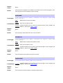
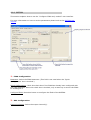
4.1.2 SMT351
This section explains how to use the "Configure FPGA-only module" user interface.
For more information on how to set the parameters please look at the SMT351 user
manual.
1 - FPGA Configuration:
Bitstream: Select the FPGA bitstream. (This field is not used when the "Quick
Configuration" box is checked.)
Quick Configuration: Check this check box if the FPGA has already been configured with
the right bitstream. When this check box is checked, only a start key is sent to the FPGA
to reconfigure it.
Configure FPGA: Press this button to configure the FPGA of the SMT391.
2 - Acquisition:
From host comport / From SDB: Select the origin of the input data.
If the input data comes from the host comport, the followings parameters define the
signal to save into the SMT351 memory:
Sampling Frequency: Set the sampling frequency in MHz.
Signal Frequency: Set the signal frequency in MHz.
Signal selection: Select the type of signal to write to the SMT351 memory.
Address: Set the address for the memory from where to read.
Bytes to acquire: Set the size of the acquisition in bytes.
File to save data: Set the file to which the data should be written.
Acquire data: Press this button to start an data acquisition.
4.1.3 SMT381
This section explains how to use the "Configure FPGA-only module" user interface.
For more information on how to set the parameters please look at the SMT381 user
manual.
1 - FPGA Configuration:
Bitstream: Select the FPGA bitstream. (This field is not used when the "Quick
Configuration" box is checked.)
Quick Configuration: Check this check box if the FPGA has already been configured with
the right bitstream. When this check box is checked, only a start key is sent to the FPGA
to reconfigure it.
Configure FPGA: Press this button to configure the FPGA of the SMT391.
2 - DAC Configuration:
Direct data / Memory data: Select the source of the input data.
Sampling Frequency: Set the sampling frequency for the DACs of the SMT381. The range
is from 50MHz to 500MHz.
Signal Frequency: Set the signal frequency of the signal to write to the DAC memories.
Signal selection: Select the type of signal to write to the DAC memories.
On board clock: Check this check box if you are using the on board clock.
Configure DAC: Press this button to configure the DACs of the SMT381.
4.1.4 SMT384
This section explains how to use the "Configure FPGA-only module" user interface.
For more information on how to set the parameters please look at the SMT384 user
manual.
1 - FPGA Configuration:
Bitstream: Select the FPGA bitstream. (This field is not used when the "Quick
Configuration" box is checked.)
Quick Configuration: Check this check box if the FPGA has already been configured with
the right bitstream. When this check box is checked, only a start key is sent to the FPGA
to reconfigure it.
Configure FPGA: Press this button to configure the FPGA of the SMT384.
2 - ADC Configuration:
Channel selection: Select the output channel(s) .
Data format: Select the format of the output data (binary or 2's complement).
VCXO type: Select the type of the VCXO fitted on the FPGA TIM (100 MHz or 245.76
MHz).
Clock Divider: Select the clock divider for the sampling frequency.
External clock: Check this check box if you are using an external clock.
Trigger inverting: Check this check box for an inverting trigger.
External trigger: Check this check box if you are using an external trigger.
Test: Check this check box to use the ADC test data as input data.
Configure ADC: Press this button to configure the ADCs of the SMT384.
3 - Acquisition:
File to save data: Set the file to which the data should be written.
Bytes to acquire: Set the size of the acquisition in bytes (or /2 14-bit samples).
Bytes to avoid: Set the number of bytes (or /2 14-bit samples) to avoid before starting
the acquisition. This can be useful in some cases. For example, the host comport on the
SMT310Q has a very small buffer that can overflow before the acquisition starts. By
setting the "Bytes to avoid" field, the comport buffer gets empty before starting the
acquisition.
Host link: Select the link used between the host and the carrier board. Most of the time it
will be the host comport but sometime it's possible to use the host RSL.
Acquire data: Press this button to start an data acquisition.
4.1.5 SMT391
This section explains how to use the "Configure FPGA-only module" user interface.
For more information on how to set the parameters please look at the SMT391 user
manual.
1 - FPGA Configuration:
Bitstream: Select the FPGA bitstream. (This field is not used when the "Quick
Configuration" box is checked.)
Quick Configuration: Check this check box if the FPGA has already been configured with
the right bitstream. When this check box is checked, only a start key is sent to the FPGA
to reconfigure it.
Configure FPGA: Press this button to configure the FPGA of the SMT391.
2 - ADC Configuration:
Sampling Frequency: Set the sampling frequency for the ADCs of the SMT391. The range
is from 50MHz to 1GHz.
Analog gain: Set the analog gain. The range is from 0 to 255.
Offset Compensation: Set the offset compensation. The range is from 0 to 255.
On board clock: Check this check box if you are using the on board clock.
DRDA channel I & Q: Set the DRDA value. This value depends of the FPGA module and
the sampling frequency.
Test: Check this check box to use the ADC test data as input data. In the next step, the
data will be saved in two separate files. One file should contain a ramp with a positive
slope. The other file should contain a ramp with a negative slope.
Channel I only ADC input: Check this check box to use the connector of channel I as the
only input source for channel I and Q.
Configure ADC: Press this button to configure the ADCs of the SMT391.
3 - Acquisition:
File to save data: Set the file to which the data should be written.
Bytes to acquire: Set the size of the acquisition in bytes (or 8-bit samples).
Bytes to avoid: Set the number of bytes (or 8-bit samples) to avoid before starting the
acquisition. This can be useful in some cases. For example, the host comport on the
SMT310Q has a very small buffer that can overflow before the acquisition starts. By
setting the "Bytes to avoid" field, the comport buffer gets empty before starting the
acquisition.
Host link: Select the link used between the host and the carrier board. Most of the time it
will be the host comport but sometime it's possible to use the host RSL.
Acquire data: Press this button to start an data acquisition.
5 Examples
The SMT1026 provides several examples to illustrate the used of the Sundance's FPGA
library.
There is an example for each supported FPGA module and a more generic one.
Those examples are organised in three folders:
•
•
•
Firmware
Host
Output
5.1 Firmware
This folder contains several firmware for the FPGA-only module.
It's installed in the following directory: "C:/Program
Files/Sundance/SMT6026/Examples/SMT391/Firmware".
Remark: SMT391 can be replaced by the number of the board you are interested in.
The bitstream have been compiled with 3L Diamond FPGA and therefore are *.app files.
The "readme.txt" file contains some information about the firmware. The source code can
be provided on demand but an NDA (Non Disclosure Agreement) has to be signed first.
Remark: The FPGA library works with the basic functionalities implemented in the
firmware supplied with the SMT1026. If bitstreams other than the ones provided with the
SMT1026 are used with the FPGA library, the software will not work properly anymore. In
those circumstances Sundance will decline all responsibilities.
5.2 Host
This folder contains the source code for the host.
It's installed in the following directory: "C:/Program
Files/Sundance/SMT6026/Examples/SMT391/Host".
Remark: SMT391 can be replaced by the number of the board you are interested in.
Source code
The source code is similar for all the supported FPGA-only modules:
123456-
Open the FPGA library.
Reset the board and TIM.
Configure the FPGA.
Configure the ADCs/DACs.
Start the acquisition on the ADCs or trigger the DACs.
Save data to file (ADCs).
Tip: Change the value of the #define directives at the beginning of the program to
change the parameters. Don't forget to recompile!
5.3 Output
This folder contains the executable application.
It's installed in the following directory: "C:/Program
Files/Sundance/SMT6026/Examples/SMT391/Output".
Remark: SMT391 can be replaced by the number of the board you are interested in.
This executable is a very simple console application aimed to show the basic use of the
SMT1026 libraries. But more complicated and flexible user interfaces can be developed
using the functionalities of the SMT1026 libraries. (See Configure FPGA-only module).