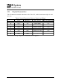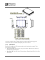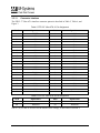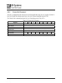
1
FFD 2.5" Ultra ATA Flash Disk
Product Specification and User Manual
October 2004
41-PS-0104-00 Rev. 1.1
DOCUMENT CONTROL INFORMATION
DCO No.:
Title
Name
Date
Issued by:
DiskOnChip Product Manager, Embedded
Division
Pnina Sharir
March 4, 2004
Updated by:
V.P. Marketing, DiskOnChip Embedded
Division
Ofer Tzur
October 18, 2004
REVISION HISTORY
Rev.
Date
1.1
October 18, 2004
Description
Updated available capacities
General
Updated sustained read performance
Section 3.3.3
Updated power consumption
Section 3.3.7
Added new security erase capability
Section 4.2.4
Updated IRIG 106 Sanitize procedure
2
Reference
Product Specification and User Manual FFD 2.5" Ultra ATA Flash Disk
Section 4.6.1.13
41-PS-0104-00 Rev. 1.1
TABLE OF CONTENTS
1. Scope ..................................................................................................................................... 5
2. Applicable Documents ......................................................................................................... 5
3. Specifications........................................................................................................................ 6
3.1. Product Definition ........................................................................................................... 6
3.2. Interface Description ...................................................................................................... 6
3.3. Characteristics................................................................................................................ 7
3.3.1.
ATA Modes ...................................................................................................................... 7
3.3.2.
Burst Read/Write Performance........................................................................................ 7
3.3.3.
Sustained Read/Write Performance ................................................................................ 7
3.3.4.
Access Time .................................................................................................................... 7
3.3.5.
Seek Time........................................................................................................................ 7
3.3.6.
Memory Capacity ............................................................................................................. 7
3.3.7.
Power Consumption ........................................................................................................ 9
3.3.8.
Endurance...................................................................................................................... 10
3.3.9.
Physical Characteristics................................................................................................. 11
3.3.10. LED Indicator ................................................................................................................. 12
3.3.11. Connector Interface ....................................................................................................... 13
3.4. Reliability - Mean Time Between Failures (MTBF)....................................................... 14
3.5. Error Detection/Correction Code (EDC/ECC) .............................................................. 14
3.6. Environmental Conditions ............................................................................................ 14
3.6.1.
Temperature .................................................................................................................. 14
3.6.2.
Altitude ........................................................................................................................... 15
3.6.3.
Relative Humidity ........................................................................................................... 15
3.6.4.
Shock ............................................................................................................................. 15
3.6.5.
Vibration......................................................................................................................... 15
4. FFD 2.5” Ultra ATA Drive Configuration ........................................................................... 16
4.1. Master and Slave Jumper Settings .............................................................................. 16
4.2. Optional Jumper Setting............................................................................................... 17
4.2.1.
Secure Erase Jumper .................................................................................................... 17
4.2.2.
Write-Protect Jumper Settings....................................................................................... 17
4.2.3.
Optional Jumper ............................................................................................................ 17
4.2.4.
Security Erase Via the Main Connector......................................................................... 18
4.3. Interface Connectors .................................................................................................... 18
4.4. ATA Cable .................................................................................................................... 19
4.5. Supported ATA Commands ......................................................................................... 19
3
Product Specification and User Manual FFD 2.5" Ultra ATA Flash Disk
41-PS-0104-00 Rev. 1.1
4.6. Vendor-Specific Commands......................................................................................... 20
4.6.1.
Sanitize .......................................................................................................................... 20
4.6.2.
Security Erase Functionality .......................................................................................... 28
4.6.3.
Configuration.................................................................................................................. 29
4.6.4.
Sanitizing Partitions ....................................................................................................... 31
4.6.5.
S.M.A.R.T Command..................................................................................................... 32
4.6.6.
Format Unit Command .................................................................................................. 33
5. Firmware Upgrade............................................................................................................... 34
6. Mount Time .......................................................................................................................... 34
7. Compatibility ....................................................................................................................... 34
8. Label Information ................................................................................................................ 35
9. Built-In Test (BIT) ................................................................................................................ 36
10. Installing and Using the FFD 2.5” Ultra ATA .................................................................... 37
10.1. Kit Contents.................................................................................................................. 37
10.2. Visual Inspection .......................................................................................................... 37
10.3. Handling Instructions.................................................................................................... 37
10.4. Installation .................................................................................................................... 38
10.4.1. System Requirements ................................................................................................... 38
10.4.2. FFD Ultra-ATA Configuration......................................................................................... 38
10.4.3. Ultra ATA Installation ..................................................................................................... 38
11. Troubleshooting.................................................................................................................. 40
11.1. The Ultra ATA is Not Identified by the System BIOS ................................................... 40
11.1.1. Basic Checks ................................................................................................................. 40
11.1.2. BIOS Setup .................................................................................................................... 40
11.1.3. Disk Settings .................................................................................................................. 40
11.2. Disk Performance is Slow ............................................................................................ 40
11.3. The Ultra ATA Functions as Additional Drive But Fails to Boot.................................... 41
11.4. Linux Installation Complete But the System Does Not Boot ........................................ 41
11.5. The New Ultra ATA Fails to Operate After Disk Duplication ........................................ 41
12. Getting Help......................................................................................................................... 42
13. Ordering Information .......................................................................................................... 43
How to Contact Us .................................................................................................................... 44
4
Product Specification and User Manual FFD 2.5" Ultra ATA Flash Disk
41-PS-0104-00 Rev. 1.1
1.
SCOPE
This specification and user manual defines the performance, design and acceptance requirements
for the FFD 2.5” Ultra ATA Flash Disk. It also provides instructions for proper installation and
use.
2.
APPLICABLE DOCUMENTS
•
ANSI-INCITS.361-2002 (ATA-6)
•
ANSI-NCITS.340-2000 (ATA-5)
•
ANSI-NCITS.317-1998 (ATA-4)
•
ANSI-X3.298-1997 (ATA-3)
•
ANSI-X3.279-1996 (ATA-2)
5
Product Specification and User Manual FFD 2.5" Ultra ATA Flash Disk
41-PS-0104-00 Rev. 1.1
3.
SPECIFICATIONS
3.1. Product Definition
The Ultra ATA is a non-volatile mass memory storage unit equipped with an ATA interface. The
Ultra ATA, whose dimensions enable mounting in a standard 2.5” disk drive enclosure, contains
the following components:
•
CPU
•
2.5” ATA connector
•
ATA controller
•
Flash memory
Figure 1: FFD 2.5” Ultra ATA Block Diagram
3.2. Interface Description
The Ultra ATA interface complies with the ATA-6 standard. For specific details refer to the
applicable documents, as specified in Section 2.
6
Product Specification and User Manual FFD 2.5" Ultra ATA Flash Disk
41-PS-0104-00 Rev. 1.1
3.3. Characteristics
3.3.1.
ATA Modes
The Ultra ATA supports the following ATA modes:
•
PIO mode 0, 1, 2, 3, 4
•
DMA mode 0, 1, 2
•
Ultra DMA mode 0, 1, 2, 3, 4, 5
3.3.2.
Burst Read/Write Performance
The Ultra ATA burst read/write rate is 100 MB/sec.
3.3.3.
Sustained Read/Write Performance
The Ultra ATA meets the performance requirements specified in Table 1. Performance was
measured on a computer using the following setup:
•
Capacity: 4GB
•
Configuration: Ultra DMA Mode 5, with 128K blocks aligned on 128K boundaries
•
Platform: ASUS P4T533-C with Intel 2.4 GHz
•
Testing utilities:
o
H2Bench (DOS)
o
H2benchW (Windows XP)
Table 1: FFD 2.5” Ultra ATA Ultra DMA Mode 5 Transfer Rates
Burst Rate1
(MB/sec)
Sustained2 Rate 128KBs Blocks
(MB/sec)
Read
100.0
45.0
Write
100.0
40.0
Operation
3.3.4.
Access Time
Maximum access time for the Ultra ATA is < 0.04 msec.
3.3.5.
Seek Time
The Ultra ATA has no seek time.
3.3.6.
Memory Capacity
Ultra ATA memory capacity information is described in Table 2.
7
Product Specification and User Manual FFD 2.5" Ultra ATA Flash Disk
41-PS-0104-00 Rev. 1.1
Table 2: FFD 2.5" Ultra ATA Capacities
Number of
Number of
Number of
Unformatted Total Number of
Current CHS
Disk Capacity User-Addressable Logical Sectors Logical Heads Logical Cylinders
Capacity
(Words 3 and 55
(Words 1 and 54 after
per Track
(MB)
Sectors in LBA
(Sectors)
after power-on of power-on) of IDENTIFY (Words 57/58 after
(Words 6 and 56
Mode
8
(Words 60/61 of
IDENTIFY information)
after power-on of
IDENTIFY
information)
IDENTIFY
information)
information)
power-on of
IDENTIFY
information)
1024
1982464
63
16
1936
1951488
2048
3995648
63
16
3963
3994704
4096
8022016
63
16
7958
8021664
8192
16074752
63
16
15947
16074576
12288
24127488
63
16
16383
16514064
16384
32180224
63
16
16383
16514064
20480
40232960
63
16
16383
16514064
24576
48285696
63
16
16383
16514064
32768
64393216
63
16
16383
16514064
40960
80498688
63
16
16383
16514064
49152
96604160
63
16
16383
16514064
57344
112711680
63
16
16383
16514064
65536
128817152
63
16
16383
16514064
73728
144922624
63
16
16383
16514064
81920
161030144
63
16
16383
16514064
90112
177135616
63
16
16383
16514064
98304
193241088
63
16
16383
16514064
106496
209348608
63
16
16383
16514064
114688
225454080
63
16
16383
16514064
122880
241559552
63
16
16383
16514064
131072
257667072
63
16
16383
16514064
Product Specification and User Manual FFD 2.5" Ultra ATA Flash Disk
41-PS-0104-00 Rev. 1.1
3.3.7.
Power Consumption
The Ultra ATA requires input voltage of +5VDC, with a tolerance of 5% (4.75V-5.25V) and a
maximum ripple of 250 mV peak-to-peak. Table 3 describes the power consumption based on
capacity. The power consumptions depend on the disk capacity and the flash components being
used.
Table 3: FFD Ultra ATA Typical Power Consumption (Watts/mA)
Disk Mode/Unformatted
Disk Capacity
1GB
8GB
32GB
56GB
Power Mode STANDBY
2.54w/500mA
2.48w/489mA
3.29w/568 mA
2.84 w/568 mA
Power Mode IDLE
2.54w/500mA
2.66w/524mA
3.29w/568 mA
2.9 w/580 mA
Sustained Write/Read
2.64w/520mA
2.66w/524mA
3.29w/568 mA
3.0 w/600 mA
Sanitize ERASE/FILL
2.69w/530mA
3.02w/595mA
4.78w/940 mA
5.7 w/1140 mA
9
Product Specification and User Manual FFD 2.5" Ultra ATA Flash Disk
41-PS-0104-00 Rev. 1.1
3.3.8.
Endurance
The Ultra ATA sustains more than 5,000,000 erase cycles and an unlimited number of read
cycles. Performance is enhanced by the following features:
•
Dynamic Wear-Leveling Algorithm: This algorithm guarantees the use of all flash blocks
at the same level of stress (write/erase cycle). The dynamic wear-leveling algorithm
eliminates situations where repeated writes to the same logical location cause flash block
wear-out. The dynamic wear-leveling algorithm functions by mapping logical blocks to
physical blocks (transparent to the customer application).
•
Garbage Collection Process: The garbage collection process eliminates the need to perform
erasure prior to every write, thus eliminating excessive disk deterioration.
•
EDC/ECC (Error Detection Code/Error Correction): The EDC/ECC extends disk
endurance by detecting and then fixing flash bits.
•
Bad-Block Mapping Algorithm: This algorithm replaces bad blocks with new ones from
available spares.
10
Product Specification and User Manual FFD 2.5" Ultra ATA Flash Disk
41-PS-0104-00 Rev. 1.1
3.3.9.
Physical Characteristics
Table 4 contains the nominal dimensions of the Ultra ATA, with the maximum weight for each
unit case.
Table 4: Nominal Dimensions, Maximum Capacity and Weight
Inches
Millimeters
Max. Capacity
Max. Unit Weight (kg)
A
0.370
9.4
8GB=8192MB
0.10
B
0.527
13.4
32GB=32768MB
0.14
C
0.685
17.4
56GB=57344MB
0.18
D
0.842
21.4
80GB=81920MB
0.22
F
1.157
29.9
128GB=131072MB
0.28
W:
2.75
69.85
-
-
L:
3.945
100.2
-
-
H:
For detailed mounting configuration dimensions, refer to Figure 2.
11
Product Specification and User Manual FFD 2.5" Ultra ATA Flash Disk
41-PS-0104-00 Rev. 1.1
1
Figure 2: FFD 2.5" Ultra ATA Assembly
A1 in Figure 2 indicates the case heights, which are available in dimensions ranging from
9.4 mm to 29.9 mm. For available cases heights, please refer to Table 4.
3.3.10.
LED Indicator
The Ultra ATA includes two LEDs, one green and one red, located on the rear panel. These
LEDs indicate the following:
•
Power (Green) LED: This is the Ultra ATA power indicator. When the Power LED is lit,
the Ultra ATA is receiving power.
•
Busy (Red) LED: This is the Ultra ATA busy indicator. When the Busy LED is lit, the Ultra
ATA is active.
12
Product Specification and User Manual FFD 2.5" Ultra ATA Flash Disk
41-PS-0104-00 Rev. 1.1
3.3.11.
Connector Interface
The FFD 2.5” Ultra ATA interface connector pinout is described in Table 5, Table 6, and
Figure 3.
Table 5: FFD 2.5” Ultra ATA J1 Pin Assignment
Pin #
Signal Name
Pin #
Signal Name
1
RESET-
2
GND
3
HD7
4
HD8
5
HD6
6
HD9
7
HD5
8
HD10
9
HD4
10
HD11
11
HD3
12
HD12
13
HD2
14
HD13
15
HD1
16
HD14
17
HD0
18
HD15
19
GND
20
KEY
21
DMARQ
22
GND
23
HIOW-
24
GND
25
HIOR-
26
GND
27
IORDY
28
CSEL
29
DMACK-
30
GND
31
INTRQ
32
IOCS16-
33
HA1
34
PDIAG
35
HA0
36
HA2
37
CS0-
38
CS1-
39
DASP-
40
GND
41
VCC
42
VCC
43
GND
44
Reserved
Table 6: FFD 2.5” Ultra ATA J2 Pin Assignment
Pin #
Signal Name
47
49
Pin #
Signal Name
48
Reserved
50
Reserved
Pins 47, 48, 49 and 50 are used for the Master/Slave settings, as described in Section 4.
13
Product Specification and User Manual FFD 2.5" Ultra ATA Flash Disk
41-PS-0104-00 Rev. 1.1
43
1
49 47
44
Pin# 20 - Missing 2
50 48
Figure 3: FFD 2.5" Ultra ATA Pin Configuration
3.4. Reliability - Mean Time Between Failures (MTBF)
The following MTBF statistics for the Ultra ATA were calculated based on Telcordia SR-332,
GB, 25°C:
•
8GB capacity: 1,493,418 hours
•
16GB capacity: 835,876 hours
•
80GB capacity: 444,504 hours
•
128GB capacity: 229,552 hours
A detailed report can be supplied upon request.
3.5. Error Detection/Correction Code (EDC/ECC)
The Ultra ATA has embedded error detection and error correction hardware and software
mechanisms. The EDC/ECC uses the BCH algorithm, which can detect up to 5 errors in
512 bytes of data, and correct up to 4 errors.
3.6. Environmental Conditions
The Ultra ATA complies with the specified performance requirements after exposure to
non-operating environmental conditions, or during and after exposure to operating environmental
conditions.
3.6.1.
Temperature
3.6.1.1 Operating
The Ultra ATA operates without degradation over the following ambient air temperature range
(the maximal temperature change rate shall not exceed 5°C per minute):
•
Commercial temperature version: 0°C to +70°C
•
Enhanced temperature version: -25°C to +75°C
•
Extended/Industrial temperature version: -40°C to +85°C
14
Product Specification and User Manual FFD 2.5" Ultra ATA Flash Disk
41-PS-0104-00 Rev. 1.1
3.6.1.2 Non-Operating
The Ultra ATA complies with the specified performance requirements after exposure to the
following conditions (the maximal temperature change rate shall not exceed 5°C per minute):
•
Nominal ambient temperature of -55°C for less than 24 hours
•
+95°C for a period of less than 24 hours
3.6.2.
Altitude
The Ultra ATA is capable of full operation at altitudes from sea level to 80,000 feet above sea
level, and can withstand air transportation in non-pressurized flights at altitudes of up to 80,000
feet above sea level.
3.6.3.
Relative Humidity
The Ultra ATA withstands 5% to 95% non-condensing relative humidity.
3.6.4.
Shock
The Ultra ATA operates without degradation when subjected to shock testing of 1500 G halfsine pulses of 0.5 ms.
Shock analysis was performed according to standard MIL-STD-810F.
3.6.5.
Vibration
The Ultra ATA operates without degradation when subjected to the following vibration
conditions:
•
16.3 G rms
•
Random vibrations: 3 vibration axes, 20 Hz to 2000 Hz.
Vibration analysis was performed according to standard MIL-STD-810F.
15
Product Specification and User Manual FFD 2.5" Ultra ATA Flash Disk
41-PS-0104-00 Rev. 1.1
4.
FFD 2.5” ULTRA ATA DRIVE CONFIGURATION
4.1. Master and Slave Jumper Settings
Prior to mounting the drive in the system drive bay, the Ultra ATA must be configured according
to Figure 4 and Figure 5.
Figure 4: FFD 2.5" Ultra ATA Address Setting by Jumper
Figure 5: FFD 2.5" Ultra ATA Slave Setting by Jumper
16
Product Specification and User Manual FFD 2.5" Ultra ATA Flash Disk
41-PS-0104-00 Rev. 1.1
4.2. Optional Jumper Setting
The Ultra ATA has an optional header located on the back panel that supports the following
options:
•
Secure Erase
•
Write Protect
The Write Protect jumper may not be modified when the unit is powered on.
4.2.1.
Secure Erase Jumper
When a jumper is placed between positions 1 - 2 of the J15 header, the Ultra ATA erases the
media.
4.2.2.
Write-Protect Jumper Settings
When a jumper is placed between positions 3 - 4 of the J15 header, the Ultra ATA is write
protected.
4.2.3.
Optional Jumper
Positions 5 - 6 of the J15 header are reserved.
Note: The Secure Erase jumper overrides the Write-Protect jumper and erases the media.
Connector's Pin Functionality
Short Pin . Functional
1-2
3-4
5-6
SECURE
ERASE
W RITE
PROTECT
OPTIONAL
Detail A
SECURE
WRITE
OPTIONAL PROTECT ERASE
Figure 6: FFD 2.5" Ultra ATA Write Protect Jumper Settings
17
Product Specification and User Manual FFD 2.5" Ultra ATA Flash Disk
41-PS-0104-00 Rev. 1.1
4.2.4.
Security Erase Via the Main Connector
The Ultra ATA also provides the option of initiating the security erase interrupt via the main
connector. This option is enabled if the two missing key pins shown in Figure 7 are in place.
Note: The Ultra ATA must be ordered with a customized main connector for this option to be
available.
Pin# 45 GND
1 49 47
43
44
Pin# 20 - Missing 2
50 48
Pin# 46
Security Erase
Figure 7: FFD 2.5” Ultra ATA with Main Connector Security Erase Option
4.3. Interface Connectors
The Ultra ATA has a 2.00 mm pitch interface connector located on the rear panel. The DC power
and ATA bus are input through a non-shielded 44-pin flat cable.
Contact #20 - Blocked
Contact #1
Female connector 44pins
Figure 8: FFD 2.5” Ultra ATA Interface Connector
It is recommended that the mating connector be blocked at pin 20 using a special plastic key (key
can be ordered from the connector manufacturer). This prevents possible damage to the disk
caused by connecting the cable with a 180º rotation.
18
Product Specification and User Manual FFD 2.5" Ultra ATA Flash Disk
41-PS-0104-00 Rev. 1.1
4.4. ATA Cable
The cable length should not exceed 18 inches.
Note: According to ATA standards, an 80-conductor cable is required to use the Ultra ATA in
Ultra DMA modes 3-5.
4.5. Supported ATA Commands
The Ultra ATA supports the commands listed in Table 7. For a complete description of these
commands, refer to the ATA-6 Standard.
Table 7: ATA Commands
Command Name
Command Code (HEX)
CHECK POWER MODE
98h E5h
DOWNLOAD MICROCODE
92h
EXECUTE DEVICE DIAGNOSTIC
90h
FLUSH CACHE
E7h
FORMAT UNIT
F7h
IDENTIFY DEVICE
ECh
IDENTIFY DEVICE DMA
EEh
IDLE
97h E3h
IDLE IMMEDIATE
95h E1h
INITIALIZE DEVICE PARAMETERS
91h
NOP
00h
READ BUFFER
E4h
READ DMA (w/ retry)
C8h
READ DMA (w/o retry)
C9h
READ MULTIPLE
C4h
READ SECTOR(S) (w/ retry)
20h
READ SECTOR(S) (w/o retry)
21h
READ VERIFY SECTOR(S) (w/ retry)
40h
READ VERIFY SECTOR(S) (w/o retry)
41h
RECALIBRATE
10h
SANITIZE (including fast secure erase)
82H
SECURITY DISABLE PASSWORD
F6h
SECURITY ERASE PREPARE
F3h
SECURITY ERASE UNIT
F4h
SECURITY FREEZE
F5h
SECURITY SET PASSWORD
F1h
SECURITY UNLOCK
F2h
SEEK
70h
19
Product Specification and User Manual FFD 2.5" Ultra ATA Flash Disk
41-PS-0104-00 Rev. 1.1
Command Name
Command Code (HEX)
SET FEATURES
EFh
SET MULTIPLE MODE
C6h
SLEEP
99h E6h
SMART
B0h
STANDBY
96h E2h
STANDBY IMMEDIATE
94h E0h
WRITE BUFFER
E8h
WRITE DMA (w/ retry)
CAh
WRITE DMA (w/o retry)
CBh
WRITE MULTIPLE
C5h
WRITE SECTOR(S) (w/ retry)
30h
WRITE SECTOR(S) (w/o retry)
31h
WRITE VERIFY
3Ch
IRIG-106 READ FAILED SANITIZE BLOCKS LIST
81h
IRIG-106 READ FAILED SANITIZE BLOCKS DATA
83h
4.6. Vendor-Specific Commands
4.6.1.
Sanitize
4.6.1.1 Sanitize (Purge) Command Interface
The Sanitize command enables distraction (purging/declassifying) of the information on the
media.
Bad blocks accumulated since the unit was manufactured will undergo the same process as good
blocks. The default sanitize procedure can be activated using either the Sanitize command itself,
or using the Sanitize Interrupt command.
The Sanitize command provides a high degree of flexibility, which enables executing
declassification procedures defined in various standards by providing different arguments to the
command.
Specifically, the Sanitize command parameters enable defining up to three stages of the
declassification process. Each stage can be either erasing the media and overwriting it with a
given character, or erasing the media and filling it with random information a specified number of
times.
If the number of erase-fill cycles is 0, the Sanitize command performs a complete erase but does
not fill the media. This is the fastest option; and is also known as the Security Erase option.
20
Product Specification and User Manual FFD 2.5" Ultra ATA Flash Disk
41-PS-0104-00 Rev. 1.1
The structure of the Security Erase command is described in Table 8.
Table 8: Vendor-Specific Sanitize Command
Register
7
6
Features
5
4
3
2
1
0
Secondary operation code
Sector Count
Master command
Sector Number
Parameter 1
Cylinder Low
Parameter 2
Cylinder High
Parameter 3
Device/Head
Partition Mask
Command
D
1
1
82h
The Secondary Operation code may be one of the following:
•
0x21 (corresponding to the character ‘!’): Immediately activates the Sanitize procedure.
•
0x22 (corresponding to the character ‘”’): Immediately activates the Sanitize procedure with
bad-block management according to IRIG-106
•
0x44 (corresponding to character ‘D’): Saves the specified parameters as the default Sanitize
configuration, but does not activate the Sanitize procedure itself.
•
0x45 (corresponding to character ‘E’): Saves the specified parameters as the default Sanitize
configuration according to IRIG-106, but does not activate the Sanitize procedure itself.
The default Sanitize procedure is factory-preset to the Security Erase option (erase the media
without media fill).
The Master Command has the following layout:
Bits 6-7: Subcommand selection
Value of 00b: Execute default Sanitize procedure
Value of 01b: Execute 1 subcommand, defined in bits 0-1
Value of 10b: Execute 2 subcommands, defined in bits 0-1 and 2-3
Value of 11b: Execute 3 subcommands, defined in bits 0-1, 2-3 and 4-5
Attempting to save the default Sanitize configuration (option ‘D’) using subcommand selection
00b will result in an aborted command and no changes will be made.
When Master Command specifies only 1 or 2 subcommands, parameters for the remaining
subcommands are reserved and should be set to 0 for compatibility with future versions.
For the default Sanitize procedure, all other bits in the Master Command and parameters1-3 are
reserved and should be set to 0 for compatibility with future versions.
Bits 0-1, 2-3 and 4-5 of the Master Command contain the following subcommands:
Value of 0: Erase and fill with given character. The character is provided in the corresponding
parameter.
21
Product Specification and User Manual FFD 2.5" Ultra ATA Flash Disk
41-PS-0104-00 Rev. 1.1
Value of 1: Erase and fill with random data, several times. The number of erase/fill loops is
provided in the corresponding parameter. Zero number of loops means erase once and do not fill.
Only the 7 least significant bits in the parameter are used to specify the number of loops. The
most significant bit is reserved for future extensions.
Value of 2 or 3: These subcommands are reserved for future extensions.
Parameter1 corresponds to the subcommand in bits 0-1.
Parameter2 corresponds to the subcommand in bits 2-3.
Parameter3 corresponds to the subcommand in bits 4-5.
Partition Mask is either a bitmap of partitions to be sanitized or value 0. In the bitmap mode,
least-significant bit 1 corresponds to partition 0. Value of zero is a special value; it corresponds
to sanitizing the whole media regardless of partition configuration.
For example, Value of 0xF (or 1111 binary) corresponds to sanitizing of all 4 partitions,
Value of 0x8 (or 1000 binary) corresponds to sanitizing partition number 3,
Value of 0x1 (or 0001 binary) corresponds to sanitizing partition number 0,
Value of 0x5 (or 0101 binary) corresponds to sanitizing partitions 0 and 2,
Value of 0 (or 0000 binary) corresponds to sanitizing the whole media.
See Section 4.6.4 for additional information on sanitizing partitions.
4.6.1.2 Compliance with Existing Sanitize (Purge) Standards
The interface specified in Table 9 enables defining a wide range of Sanitize procedures.
Table 9: Supported Sanitizing Procedures
Master
Command
Parameter 1
Parameter 2
Parameter 3
Execute the default Sanitize procedure.
0x00
0x00
0x00
0x00
Erase the media (Security Erase).
0x41
0x00
0x00
0x00
USA-AF AFSSI 5020
0x41
0x01
0x00
0x00
0x85
0x01
0x00
0x00
0x84
Char
0x00
0x00
0x81
0x02
Char
0x00
Operation
Erase the media and overwrite with random
data.
USA Navy NAVSO P-5239-26
Erase the media and overwrite with random
data, then erase again.
DoD 5220.22-M
Erase the media and overwrite with single
character, then erase again.
NSA Manual 130-2
Erase the media and overwrite with random
data 2 times, then erase and overwrite with
a character.
22
Product Specification and User Manual FFD 2.5" Ultra ATA Flash Disk
41-PS-0104-00 Rev. 1.1
Master
Command
Parameter 1
Parameter 2
Parameter 3
0xC1
0x01
Char
~Char
0xD0
Char
~Char
0x01
0xD0
0x55
0xAA
0x00
Erase the media and overwrite with random
data (different data each time) 21 times.
0x41
0x15
0x00
0x00
Erase the media and overwrite with random
data (different data each time) 381 times
0xD5
0x7F
0x7F
0x7F
Operation
USA-Army 380-19
Erase the media and overwrite with random
data, erase and overwrite with a character,
then erase and overwrite with complement
of the character.
NISPOMSUP Chap 8, Sect. 8-501
Overwrite all locations with a character, its
complement, and then random data.
IREC (IRIG) 106:
Erase the media, overwrite with 0x55,
erase, overwrite with 0xAA, erase.
Notes: 1. Before every overwrite process, all blocks are erased as per the flash specification.
2. Blocks subjected to the Sanitize procedure are all blocks not registered in the original
manufacturer’s Bad Block Table.
4.6.1.3 Sanitize Interrupt
The Sanitize Interrupt command has the following characteristics:
•
The Ultra ATA receives the Sanitize Interrupt at any time.
•
The Sanitize Interrupt initiates the immediate execution of the default Sanitize procedure.
•
The default factory-preset Sanitize procedure is to erase the entire media and leave it empty
(to perform the Security Erase option).
•
If unit is powered up with Sanitize Interrupt active, the default Sanitize procedure is
launched immediately.
•
If the Sanitize Interrupt is still active upon completion of the default Sanitize procedure, the
Ultra ATA restarts the default Sanitize procedure. This cycle is repeated indefinitely for as
long as the Sanitize Interrupt command is active.
Note: Please contact the M-Systems sales offices for information regarding the available
hardware Sanitize Interrupt options.
4.6.1.4 Auto-Resume Sanitize Feature
When Auto-Resume is enabled (the factory default setting), if a power interruption occurs during
a Sanitize procedure the Ultra ATA restarts the Sanitize procedure on the next power-up.
If the Sanitize Interrupt command is active during power-up, the unit first completes the Sanitize
procedure that was initiated before the power interruption. If the Sanitize Interrupt command is
23
Product Specification and User Manual FFD 2.5" Ultra ATA Flash Disk
41-PS-0104-00 Rev. 1.1
still active when the procedure is complete, the Ultra ATA re-launches the default Sanitize
procedure, as described in Table 9.
4.6.1.5 Random Data Written During the Sanitize Procedure
The random data used to overwrite user data is a digest of pseudo-random generation and real
random data. The pseudo-random generation is seeded in such a manner that even if the Ultra
ATA launches the Sanitize command under identical external conditions (for example, if the unit
is powered on with Sanitize Interrupt active), it will produce different seeds and different
pseudo-random data.
4.6.1.6 LED Activity During the Sanitize Procedure
During the Format and Sanitize procedures, the red LED provides the following indications:
a. Remains lit during the Erase phase (for the Sanitize procedure, during each erase phase)
b. Blinks during the Media Fill phase (for the Sanitize procedure, during each fill phase)
c. Remains lit for a short period while the disk achieves ready status after completing the
Sanitize procedures.
4.6.1.7 Using the Ultra ATA After a Sanitize Procedure
After performing Sanitize Procedure, if fill option is not activated, the user must perform a
low-level format on the media. Failing to perform the low-level format may result in a longer
start-up time.
4.6.1.8 Sanitizing Based on DoD 5220.22-M
The USA DoD 5220.22-M National Industrial Security Program Operating Manual (NISPOM),
January 1995, specifies the sanitization processes for each media type (in order to be considered
declassified) in Chapter 8, Automated Information System Security. For Flash EPROM media
type, the sanitize process is as follows:
•
“Overwrite all addressable location with a single character.”
Then
•
“Perform a full chip erase as per manufacturer’s data sheet.”
The Ultra ATA complies with the above requirement, as described in Table 9.
4.6.1.9 Sanitizing Based on NSA Manual 130-2
The USA National Security Agency (NSA) specifies the procedure for sanitizing semiconductor
memory devices in its 130-2 Media Declassification and Destruction Manual (Paragraph 5,
Section 7). In the updated document version dated November 2000 Section 4.6c indicates the
procedure for sanitizing EEPROM:
•
“Overwriting all locations with a pseudo-random pattern twice”.
Then
•
“Overwriting all locations with a known pattern”.
The Ultra ATA complies with the above requirement, as described in Table 9.
24
Product Specification and User Manual FFD 2.5" Ultra ATA Flash Disk
41-PS-0104-00 Rev. 1.1
4.6.1.10 Sanitizing Based on USA Air Force AFSSI 5020
The USA Air Force System Security Instruction (AFSSI) 5020, dated 20 August, 1996, specifies
the procedure for sanitizing confidential media. Chapter 5, Semiconductor Devices, describes the
security procedure for all types of semiconductor media. In Paragraph 5.3, the procedure for
sanitizing flash memory is described as follows:
•
“Pulsing the erase control gate and verifying the erasure”.
Then
•
“Overwrite all bit locations with arbitrary unclassified data”.
The Ultra ATA complies with the above requirement, as described in Table 9.
4.6.1.11 Sanitizing (Purging) Based on USA Army Regulation 380-19
The USA Army Regulation 380-19, Information Systems Security (ISS), effective 27 March,
1998, provides the security requirements for systems processing Special Access Program (SAP)
information and describes the ISS policy as it applies to security in hardware, software
procedures, telecommunication, personal use, physical environment, networks and firmware.
Section VII, Automated Information System Media, Section 2-20, describes cleaning, purging,
declassifying and destroying media. Appendix F-2 describes the following for sanitizing flash
EPROM (FEPROM):
•
“Overwrite all location with a random character, a specific character, then its complement”
Then
•
“Check with the DAA (Designated Approval Authority)/SCO (Service Certifying
Organization) to see if additional procedures are required”.
The Ultra ATA complies with the above requirement, as described in Table 9.
4.6.1.12 Sanitizing (Purging) Based on USA Navy NAVSO P-5239-26
The Navy Staff Office Publication (NAVSO) 5239, “Information Systems Security (INFOSEC)
Program Guidelines” is issued by the Naval Information Systems Management Center and
provides policy, guidelines, and procedures for clearing and purging computer system memory
and other storage media for release outside of and for reuse within controlled environments. It
pertains to both classified and sensitive unclassified information. Implements DOD 5200.28-M
and CSC-STD-005-85. Chapter 3 describes the cleaning and purging of data storage media, and
section 3.5 describes the purging of EEPROM and EAROM. To purge EEPROM:
•
”Overwrite all location with any pattern,” then erase.
The Ultra ATA complies with the above requirement, as described in Table 9.
4.6.1.13 Declassification Based on IRIG-106 (NTISSP-9)
The Telemetry Group (TG) of the Range Commanders Council (RCC) has prepared documents
to foster the compatibility of telemetry transmitting, receiving, and signal processing equipment
at the member ranges under the cognizance of the RCC.
25
Product Specification and User Manual FFD 2.5" Ultra ATA Flash Disk
41-PS-0104-00 Rev. 1.1
IRIG (Inter-Range Instrumentation Group) 106 are set of Telemetry standards which provide the
necessary criteria on which to base equipment design and modification.
The National Telecommunication & Information Security Systems (NTISSP-9) Chapter 10
describes the requirements for SOLID STATE RECORDER STANDARD. Section 10.8
(declassification) addresses declassification for various Solid-State Disks as follows:
•
First Erase – Every memory block on the board is erased
•
First write 0x55 – Every memory chip location is recorded with a pattern 0x55
•
Second Erase – Every memory block on the board is erased
•
Second write 0xAA – Every memory chip location is recorded with a pattern 0xAA
•
Third Erase – Every memory block on the board is erased
M-Systems’ FFD Sanitize feature complies with the above requirements as described in Table 9.
IRIGS-106 Usage
After initiating the Sanitize procedure with bad-block management according to IRIG-106, the
number of blocks that failed to erase is returned in the registers of the Ultra ATA, as defined in
Table 10.
Table 10: IRIG-106 Return Results
Register
7
6
5
4
Error
3
2
Na
Sector Number
Failed sanitize blocks (7:0)
Cylinder Low
Failed sanitize blocks (15:8)
Cylinder High
Failed sanitize blocks (23:16)
Status
26
0
0
Sector Count
Device/Head
1
NA
NA
NA
DEV
BSY
DRDY
DF
NA
Failed sanitize blocks (27:24)
DRQ
Product Specification and User Manual FFD 2.5" Ultra ATA Flash Disk
NA
NA
ERR
41-PS-0104-00 Rev. 1.1
IRIG-106 READ FAILED SANITIZE BLOCKS LIST Command
The IRIG-106 READ FAILED SANITIZE BLOCKS LIST Command is a PIO DATA IN
command. The data transfer is done in single sectors.
This command is used to retrieve the list of all the blocks in the media that failed to pass the
sanitize process.
Table 11: IRIG-106 READ FAILED SANITIZE BLOCKS LIST Bit Description
Register
7
6
5
4
3
Features
2
1
0
0x07
Sector Count
Max sector count
Sector Number
Na
Cylinder Low
'V'
Cylinder High
'S'
Device/Head
Partition Mask
D
Command
1
1
81h
The Max Sector Count register indicates the host allocated buffer size, in sectors. The device
may not transfer data larger than the host allocated memory.
The returned data format is 4 bytes entry per block.
IRIG-106 READ FAILED SANITIZE BLOCKS DATA
Table 12: IRIG-106 READ FAILED SANITIZE BLOCKS DATA Bit Description
Register
7
6
Features
5
4
3
2
0
Secondary Operation Code
Sector Count
Host Allocated buffer size
Sector Number
block number(0:7
Cylinder Low
block number(7:15)
Cylinder High
block number(16:23)
Device/Head
1
NA
Command
NA
NA
DEV
block number(23:27)
83h
There are 5 secondary operation codes:
•
0x00: GET_DATA_LENGTH returns the number of blocks that failed to erase in the ATA
registers, in the block number filed.
•
0x01: GET_FIRST_DATA sends the “failed to sanitize” data from the first block. The Ultra
ATA aborts the command if the sanitize command with secondary operation code 0x22 has
not been issued prior to the data retrieval request.
27
Product Specification and User Manual FFD 2.5" Ultra ATA Flash Disk
41-PS-0104-00 Rev. 1.1
•
0x02: GET_NEXT_DATA sends the next data in the pipeline. The Ultra ATA aborts the
command if it reaches the end of the data, or if the sanitize command with secondary
operation code 0x22 has not been issued prior to the data retrieval request.
•
0x03: GET_BLOCK_DATA sends the data of the requested block. The Ultra ATA aborts
the command if the sanitize command with secondary operation code 0x22 has not been
issued prior to the data retrieval request.
•
0x04: GET_BLOCK_NEXT_DATA sends the next data in the pipeline from a specific
block. The Ultra ATA aborts the command if it reaches end of the data, or if the sanitize
command with secondary operation code 0x22 has not been issued prior to the data retrieval
request.
4.6.2.
Security Erase Functionality
The Security Erase option enables quickly erasing all the data stored on the Ultra ATA. This
function is activated by the vendor-unique Sanitize command (see Section 4.6.1) or via the
Sanitize hardware interrupt triggered by the Secure Erase header (if available).
The time required to perform the security erase depends on the disk capacity and the type of
flash components being used. Table 13 describes typical time required to complete the security
erase for typical capacities.
Table 13: Typical Erase Time (According to Disk Capacity)
28
Capacity
(MB)
Time to Erase Entire
Media (sec)
Security Erase
Time to Erase Entire
Media + FILL (sec)
USA-AF AFSSI 5020
NSA 130-2
(erase + fill random
twice, erase + fill char)
1024
2.5 (+1.0 sec mount
unformatted media)
22.7 (+0.2 sec mount)
139.1 (+0.1 sec mount)
4096
10.8 (+3.7 sec mount
unformatted media)
101.1 (+0.3 sec mount)
595.1 (+0.6 sec mount)
8192
11.3 (+7.3 sec mount
unformatted media)
191.6 (+0.6 sec mount)
1138.7 (+0.6 sec mount)
16384
11.6 (+14.4 sec mount
unformatted media)
357.3 (+0.9 sec mount)
2193 (+0.9 sec mount)
32768
10.1 (+29.6 sec mount)
690.2 (+2.0 sec mount)
4326.8 (+2.0 sec mount)
Product Specification and User Manual FFD 2.5" Ultra ATA Flash Disk
41-PS-0104-00 Rev. 1.1
Typical power consumption during security erase depends on both the device capacity and on the
NAND flash type. Table 14 describes the specifications for Security Erase operations. The Ultra
ATA input voltage is +5VDC, with a tolerance of 5% (4.75V-5.25V) and maximum ripple of
250 mV peak-to-peak.
Table 14: Typical Power Consumption During Security Erase
4.6.3.
Disk Capacity (MB)
Power Consumption During
Security Erase
1024
2.69W / 530 mA
4096
3.81W / 750 mA
8192
3.91W / 770 mA
16384
3.33W / 655 mA
32768
3.33W / 655 mA
Configuration
4.6.3.1 Configurable Parameters
The following parameter can be configured:
Sanitize Partition Information for four partitions. Each partition is defined as pair of numbers,
<Start Sector> and <Partition Length in Sectors>.
4.6.3.2 Setting the Configurable Parameters
The structure of the SET PARAMETERS command is described in Table 15:
Table 15: Vendor-Specific Set Parameters Command
Register
7
6
5
Features
4
0
Sector Number
0
Cylinder Low
0
Cylinder High
0
Command
29
2
D
1
1
0
0xF0
Sector Count
Device/Head
3
0
1
B0h
Product Specification and User Manual FFD 2.5" Ultra ATA Flash Disk
41-PS-0104-00 Rev. 1.1
The command transfers one sector of data with configurable parameters to the Ultra ATA. The
format of the data is described in Table 16.
Table 16: Data Format on the Ultra ATA
Word 0
Signature: 0x4E56
Word 1
Version: 0x100
Word 2
Reserved
Word 3
Number of Parameters in whole command
Word 4
Parameter 1 ID, MSB
Word 5
Parameter 1 ID, LSB
Word 6
Parameter 1 Value, MSB
Word 7
Parameter 1 Value, LSB
Word 8
Word 251
...
...
Word 252
Parameter 63 ID, MSB
Word 253
Parameter 63 ID, LSB
Word 254
Parameter 63 Value, MSB
Word 255
Parameter 63 Value, LSB
Each parameter ID is a 32-bit number. Each parameter value is also a 32-bit number. The
following parameter IDs are currently defined:
Partition 0 Start Sector
0x10000
Partition 0 Length in Sectors
0x10001
Partition 1 Start Sector
0x10002
Partition 1 Length in Sectors
0x10003
Partition 2 Start Sector
0x10004
Partition 2 Length in Sectors
0x10005
Partition 3 Start Sector
0x10006
Partition 3 Length in Sectors
0x10007
The SET PARAMETERS command is aborted if an invalid Parameter ID or Parameter ID value
is given, for example, if the partition size exceeds the media capacity.
30
Product Specification and User Manual FFD 2.5" Ultra ATA Flash Disk
41-PS-0104-00 Rev. 1.1
4.6.3.3 Retrieving the Configurable Parameters
The structure of the GET PARAMETERS command is described in Table 17:
Table 17: Vendor-Specific Get Parameters Command
Register
7
6
5
Features
4
3
2
1
0
0xEF
Sector Count
Parameter ID bits 0-7 (LSB)
Sector Number
Parameter ID bits 8-15
Cylinder Low
Parameter ID bits 16-23
Cylinder High
Parameter ID bits 24-31 (MSB)
Device/Head
0
Command
D
1
1
B0h
The command transfers one sector of data with configurable parameters from the Ultra ATA, in
the format described in Table 16 on page 30. If the parameter ID specified in the command
registers is one of those listed in Section 4.6.3.2, the returned sector contains the value of that
single ID. In addition, a group-ID is defined as:
All Partition IDs
0x1FFFF
In response to a group-ID given in the command registers, the returned sector will contain a list
of parameter IDs from that group, and all their respective values.
4.6.4.
Sanitizing Partitions
The Ultra ATA can be subdivided into a maximum of four partitions. When configuring your
system for a Sanitize procedure, the following must be taken into account:
•
A partition may be as small as one sector, or occupy the entire media.
•
When a partition has a length of 0, if it is included in the Partition Mask it will have no
effect on the Sanitize procedure.
•
Partition values are always defined. The factory default is all partitions having length 0, i.e.
nothing is erased if you use Sanitize with a Partition Mask value other than 0 without setting
some new partition boundaries.
•
Sanitizing all four partitions is not necessarily the same as sanitizing the whole media; it
depends on the configuration of the partitions (starting block and length of each).
•
Partitions may overlap in any fashion. Their combined set of sectors will be sanitized.
•
You can define the default Sanitize procedure to have any Partition Mask.
31
Product Specification and User Manual FFD 2.5" Ultra ATA Flash Disk
41-PS-0104-00 Rev. 1.1
4.6.5.
S.M.A.R.T Command
In an effort to help users to avoid data loss, mechanical disk manufacturers incorporate logic into
their drives that acts as an “early warning system”. This system is called Self-Monitoring
Analysis and Reporting Technology, or S.M.A.R.T. The hard disk’s integrated controller works
with sensors to monitor various aspects of the drive’s performance, and determines from this
information whether or not the drive is behaving normally and reports its status. The
fundamental principle behind S.M.A.R.T. is that many problems within mechanical hard disks
do not occur suddenly, but result from a slow degradation of various mechanical components.
Mechanical characteristics commonly analyzed by the S.M.A.R.T. command are head-flying
height, number of remapped sectors, spin-up time, drive temperature and data throughput.
S.M.A.R.T implementation in the Ultra ATA takes an alternate approach. As the Ultra ATA is a
solid-state disk with no moving parts, there is no point in testing Ultra ATA mechanical
functionality. The S.M.A.R.T. command in the Ultra ATA analyzes the number of bad blocks
that were accumulated in the Ultra ATA relative to the total amount of spare blocks.
When the flash media returns a failure at a block, the data from that block is transferred to a
spare block (transparently to the host), and the failed block is marked as bad. The number of
spare blocks on the media is close to 4%, which provides balance between cost and reliability.
When the S.M.A.R.T. command is executed, subcommand is RETURN STATUS and the Ultra
ATA calculates the following parameters:
•
The total number of spare blocks reserved at the time the Ultra ATA was shipped from the
factory.
•
The current number of spare blocks available on the Ultra ATA.
For the S.M.A.R.T. command, the subcommand RETURN STATUS returns one of two possible
statuses:
•
Passed: If less than 95% of the total reserved spare blocks at the time of shipment were
already used.
•
Failed: If more than 95% of the total reserved spare blocks at the time of shipment were
already used
The S.M.A.R.T remote monitoring analysis can be used as a trigger for disk alarm and for
immediate preventative maintenance, namely to replace the Ultra ATA before it passes into
read-only mode.
32
Product Specification and User Manual FFD 2.5" Ultra ATA Flash Disk
41-PS-0104-00 Rev. 1.1
4.6.6.
Format Unit Command
The drive is shipped from the factory low-level formatted and ready for use. In order to initiate a
low-level format, the initiator must issue a low-level format command (opcode F7h).
The Format Unit command performs low-level formatting on the Ultra ATA.
Table 18: Format Unit Command
Register
7
6
5
4
3
2
D
1
1
0
Features
Sector Count
Sector Number
Cylinder Low
Cylinder High
Device/Head
Command
33
1
F7h
Product Specification and User Manual FFD 2.5" Ultra ATA Flash Disk
41-PS-0104-00 Rev. 1.1
5.
FIRMWARE UPGRADE
The Ultra ATA is a firmware upgradeable disk.
6.
MOUNT TIME
The total time required to mount the Ultra ATA, described in Table 19, depends on the device
capacity.
Table 19: Mount Time (According to Capacity, After Low-Level Format)
7.
Capacity (MB)
Duration (sec)
1024
0.1
4096
0.2
8192
0.4
16384
0.6
40960
1.3
COMPATIBILITY
The Ultra ATA is guaranteed to comply with the following requirements:
CE, UL, EN 55022 Class B, CISPR 22 Class B, AS/NZS 3548 Class B, BSMI CNS 13438 Class
B, CAN/CSA-V-3/2001.04 (VCCI), FCC Part 15 Class B, EN 61000-3-2, EN 61000-3-3, IEC
61000-4-2/3/4/5/6/8/11.
34
Product Specification and User Manual FFD 2.5" Ultra ATA Flash Disk
41-PS-0104-00 Rev. 1.1
8.
LABEL INFORMATION
The bottom cover label contains the following information:
1
2
3
5
6
4
7
8
Figure 9: FFD Ultra ATA Label
1.
Ordering Information
2.
Part Number
3.
Shipping Number
4.
ESD Warning
5.
M-Systems Logo
6.
Product Logo
7.
Declaration of Origin
8.
Compliance
35
Product Specification and User Manual FFD 2.5" Ultra ATA Flash Disk
41-PS-0104-00 Rev. 1.1
9.
BUILT-IN TEST (BIT)
The Ultra ATA performs a power-up test to ensure that its basic components are functioning.
Upon power-up the following is tested:
•
RAM
•
Boot Flash
•
ATA Controller
•
Timers
•
DMA Controller
•
Flash Media
36
Product Specification and User Manual FFD 2.5" Ultra ATA Flash Disk
41-PS-0104-00 Rev. 1.1
10. INSTALLING AND USING THE FFD 2.5” ULTRA ATA
This section provides you with the information you need to properly install your new FFD 2.5”
Ultra ATA Flash Disk. M-Systems recommends that qualified and trained personnel install the
drive.
The following chapters contain handling information, mounting considerations, address and
configuration setups, cabling and connector information and information about obtaining
technical assistance and service.
Remember - Always back up your data before adding disk drives to your system!
10.1. Kit Contents
Ensure that your kit contains the following items:
•
FFD 2.5” Ultra ATA Flash Disk
•
Four mounting screws and three jumpers, M-Systems part no. 41-pk-001-00.
If any items are missing, please contact your dealer.
10.2. Visual Inspection
Before unpacking or handling a drive, take all proper electrostatic discharge (ESD) precautions,
including personnel and equipment grounding.
Before you begin installing the Ultra ATA, inspect the package and device as follows:
•
If the shipping container appears to be damaged or water stained, notify your dealer.
•
Remove the disk from its shipping enclosure and inspect it for any damage that may have
occurred during shipment. If any damage is observed, notify your dealer.
•
Record the disk serial number and shipment date.
•
Retain the original shipping enclosure and all packing material for re-shipment.
10.3. Handling Instructions
You can prolong the life of your Ultra ATA, increase its reliability, and prevent unnecessary
damage by following the instructions listed below. Failure to follow any of these instructions
may void your warranty.
•
Always take all proper electrostatic discharge (ESD) precautions, including personnel and
equipment grounding.
•
Always operate the Ultra ATA within the environmental specifications.
•
Always use a grounded wrist strap when handling the Ultra ATA. Drives that are not
installed in the system are sensitive to ESD damage.
•
Always handle the Ultra ATA carefully.
37
Product Specification and User Manual FFD 2.5" Ultra ATA Flash Disk
41-PS-0104-00 Rev. 1.1
•
Never switch DC power to the drive by plugging an electrically live source cable into the
drive’s power connector.
•
Pay attention to the cable polarity whenever connecting the drive to the cable.
10.4. Installation
10.4.1.
System Requirements
In order to install the Ultra ATA in your system, ensure that you have the following items:
•
System mounting hardware
•
80-conductors ribbon ATA cable for the Ultra ATA for using Ultra DMA modes 3-5. A
40-conductor ribbon ATA cable will enable working in PIO and Ultra DMA modes 0-2
only. Higher speed transfers may subject to failures.
10.4.2.
FFD Ultra-ATA Configuration
Before mounting the drive into the system drive bay, you must first configure the Ultra ATA by
setting the Master/Slave and the Optional Jumpers setting jumper to comply with your system
requirements. See section 4.1 for details.
10.4.3.
Ultra ATA Installation
The Ultra ATA can be installed in the system in any mounting position. Unlike rotating disks
that have an axis of rotation, the Ultra ATA is not susceptible to damage due to its orientation.
Note: It is not necessary to perform a low-level format on the Ultra ATA. The drive is shipped
low-level formatted and ready for use.
10.4.3.1 Installing the Ultra ATA in a PC Environment
To install the Ultra ATA:
1.
Power down the PC and remove the cover.
2.
Configure the Ultra ATA jumper settings according to the information provided in
Section 4.1
3.
Connect a cable between the Ultra ATA and the host. Make sure to orient the cable so that
pin 1 of the Ultra ATA is connected to pin 1 of the host adapter.
4.
Mount the Ultra ATA in a free drive bay.
5.
Close the PC cover and power on the PC.
6.
The host BIOS sign-on message will appear and display a key sequence to enter the BIOS
setup. Set up the BIOS to recognize the Ultra ATA (refer to the BIOS documentation for the
disk installation procedure).
You are now ready to use the Ultra ATA. If you encounter any problems, refer to Section 11 for
troubleshooting information.
38
Product Specification and User Manual FFD 2.5" Ultra ATA Flash Disk
41-PS-0104-00 Rev. 1.1
10.4.3.2 Using the Ultra ATA in an MS-DOS-Based Platform
After installing the Ultra ATA (as described in Section 10.4.3), it must be installed as a disk
drive under DOS. Run the DOS commands listed below and follow the instructions displayed for
each command. For more information regarding the DOS commands, refer to your DOS manual.
1.
Run the DOS FDISK program to partition the Ultra ATA.
2.
Run the DOS FORMAT command to high-level format the Ultra ATA.
3.
If you want the Ultra ATA to be a bootable drive, run the DOS SYS command and change
its partition to active.
10.4.3.3 Using the Ultra ATA in a Windows-Based Platform
The Ultra ATA requires no special adjustments or modifications, and can be used just like a
magnetic hard drive.
10.4.3.4 Using the Ultra ATA in a Linux-Based Platform
The Ultra ATA requires no special adjustments or modifications, and can be used just like a
magnetic hard drive.
10.4.3.5 Using the Ultra ATA in Other OS/Platforms
The Ultra ATA requires no special adjustments or modifications, and can be used just like a
magnetic hard drive.
39
Product Specification and User Manual FFD 2.5" Ultra ATA Flash Disk
41-PS-0104-00 Rev. 1.1
11. TROUBLESHOOTING
11.1. The Ultra ATA is Not Identified by the System BIOS
11.1.1.
Basic Checks
Most disk problems are caused by improper disk installation. First, check the following:
•
•
•
Cable problems:
o
Homemade, short, flat ribbon cables with bad contacts or cheap cables
o
Mixing round cables with flat cables
o
Cable length exceeds the limit specified in the standard
o
Cables are too long to support the transfer rate
Device Address Conflict:
o
A new device was added with an ATA setting identical to an existing device on the bus
o
Connection is faulty
o
A cable was connected with reverse polarity
Power supply is below FFD requirements
11.1.2.
BIOS Setup
Verify that the disk is enabled in the BIOS. In most new BIOSs, there is an option to allow auto
identification of the drive. This usually works.
11.1.3.
Disk Settings
If the Ultra ATA is functioning as master device with a non-compliant slave device, the Ultra
ATA may not be identified. To prevent this failure, set the jumpers to “Master with Non-ATACompliant Slave”, as described in Section 4.1.
11.2. Disk Performance is Slow
If you are experiencing poor disk performance, it may be due to one of the following reasons:
•
The Ultra ATA is operating only with ultra DMA modes 0-2.
•
The Ultra ATA is operating in PIO mode under Windows.
•
The cable may be 40-conductor cable instead of 80-conductor cable. High transfer rates
require the proper cable.
•
DMA transfer mode may not be enabled in the Windows OS settings. Windows has a
fallback mechanism that causes the disk operating mode to revert to PIO if too many errors
occur.
40
Product Specification and User Manual FFD 2.5" Ultra ATA Flash Disk
41-PS-0104-00 Rev. 1.1
11.3. The Ultra ATA Functions as Additional Drive But Fails to Boot
If the Ultra ATA fails to boot even though the OS recognizes it as an additional drive, check the
following:
•
Verify that the partition on the drive is active. Some partitioning utilities, such as DOS
FDISK, automatically set a partition to active when the Ultra ATA is the only disk in the
system. If other disk with an active partition is present in the system, the FDISK utility does
not allow setting additional partitions as active.
•
Verify that the operating system is properly installed.
11.4. Linux Installation Complete But the System Does Not Boot
Verify that the partitions are large enough. When using small capacity drive, older installation
CD fail to properly divide the disk to partitions.
This bug was fixed in new installation utilities.
If you use your own customized Linux verify that you use the latest kernel as a base to your
modified version.
11.5. The New Ultra ATA Fails to Operate After Disk Duplication
If you duplicate an Ultra ATA drive and the new drive fails to operate, check the following:
•
Verify that the master disk is identical to the target disk.
•
Some duplicators or duplicating utilities cannot install large images (created using large
drives) on smaller drives.
•
Install the OS on the Ultra ATA and use it as the master disk.
41
Product Specification and User Manual FFD 2.5" Ultra ATA Flash Disk
41-PS-0104-00 Rev. 1.1
12. GETTING HELP
If you need technical assistance with the installation and/or configuration of your Ultra-ATA,
contact one of the sources listed on the contact page. Before you call, please be sure to have the
following information available for the customer support representative:
•
Product and serial number of your Ultra ATA.
•
Description of computer hardware (manufacturer, model, attached devices, etc.).
•
Description of your ATA host adapter and associated drivers.
•
Description of your software (operating system, version, application software, etc.).
•
A complete description of the problem.
•
The exact wording of any error messages.
Before contacting M-Systems directly, first contact your dealer. If your dealer cannot provide the
help you need, you can obtain technical support directly from M-Systems at one of the numbers
listed on the contact page.
42
Product Specification and User Manual FFD 2.5" Ultra ATA Flash Disk
41-PS-0104-00 Rev. 1.1
13. ORDERING INFORMATION
Table 20: Ordering Information for FFD 2.5” Ultra ATA
FFD-25-UATA-CCCCC-T-H
CCCCC:
Unformatted
capacity (MB)
1024, 2048, 4096, 8192, 12288, 16384, 20480, 24576, 32768, 40960,
49152, 57344, 65536, 73728, 81920, 90112, 98304, 106496, 114688,
122880, 131072 (1GB=1024MB)
T:
Temperature
range
Blank: Commercial 0°C - +70°C
N:
Enhanced -25°C - +75°C
X:
Extended -40°C - +85°C
H:
Case height
A – 9.4 mm up to 8GB=8192MB
B – 13.4 mm up to 32GB=32768MB
C – 17.3 mm up to 56GB=57344MB
D – 21.4 mm up to 80GB=81920MB
F – 29.9 mm up to 128GB=131072MB
43
Product Specification and User Manual FFD 2.5" Ultra ATA Flash Disk
41-PS-0104-00 Rev. 1.1
HOW TO CONTACT US
USA
China
M-Systems, Inc.
555 North Mathilda Avenue, Suite 220
Sunnyvale, CA 94085
Phone: +1-408-470-4440
Fax: +1-408-470-4470
M-Systems China Ltd.
Room 121-122
Bldg. 2, International Commerce & Exhibition Ctr.
Hong Hua Rd.
Futian Free Trade Zone
Shenzhen, China
Phone: +86-755-8348-5218
Fax: +86-755-8348-5418
Japan
Europe
M-Systems Japan Inc.
Asahi Seimei Gotanda Bldg., 3F
5-25-16 Higashi-Gotanda
Shinagawa-ku Tokyo, 141-0022
Phone: +81-3-5423-8101
Fax: +81-3-5423-8102
M-Systems Ltd.
7 Atir Yeda St.
Kfar Saba 44425, Israel
Tel: +972-9-764-5000
Fax: +972-3-548-8666
Taiwan
Internet
M-Systems Asia Ltd.
14 F, No. 6, Sec. 3
Minquan East Road
Taipei, Taiwan, 104
Tel: +886-2-2515-2522
Fax: +886-2-2515-2295
www.m-systems.com
General Information
[email protected]
Sales and Technical Information
[email protected]
This document is for information use only and is subject to change without prior notice. M-Systems Flash Disk Pioneers Ltd. assumes no
responsibility for any errors that may appear in this document. No part of this document may be reproduced, transmitted, transcribed, stored in a
retrievable manner or translated into any language or computer language, in any form or by any means, electronic, mechanical, magnetic,
optical, chemical, manual or otherwise, without prior written consent of M-Systems.
M-Systems products are not warranted to operate without failure. Accordingly, in any use of the Product in life support systems or other
applications where failure could cause injury or loss of life, the Product should only be incorporated in systems designed with appropriate and
sufficient redundancy or backup features.
Contact your local M-Systems sales office or distributor, or visit our website at www.m-systems.com to obtain the latest specifications before
placing your order.
© 2004 M-Systems Flash Disk Pioneers Ltd. All rights reserved.
M-Systems, DiskOnChip, DiskOnChip Millennium, DiskOnKey, DiskOnKey MyKey, FFD, Fly-By, iDiskOnChip, iDOC, mDiskOnChip,
mDOC, Mobile DiskOnChip, Smart DiskOnKey, SuperMAP, TrueFFS, uDiskOnChip, uDOC, and Xkey are trademarks or registered
trademarks of M-Systems Flash Disk Pioneers, Ltd. Other product names or service marks mentioned herein may be trademarks or registered
trademarks of their respective owners and are hereby acknowledged. All specifications are subject to change without prior notice.
44
Product Specification and User Manual FFD 2.5" Ultra ATA Flash Disk
41-PS-0104-00 Rev. 1.1