1
Puppy Pal
Senior Design Group 11
Marshall Smith
Afzal Shafi
Anson Contreras
Cameron Riesen
i
Table of Contents
1
2
Executive Summary ................................................................................................. 1
Project Description ................................................................................................... 2
2.1
2.2
2.3
Project Motivation............................................................................................... 2
Goals and Objectives ......................................................................................... 2
Project Specifications and Requirements........................................................... 3
2.3.1
2.3.2
2.3.3
2.3.4
2.3.5
2.3.6
2.3.7
2.3.8
2.3.9
3
Durability...................................................................................................... 3
Mobility ........................................................................................................ 4
Autonomous Movement ............................................................................... 5
Remote Control ........................................................................................... 6
Wireless Charging ....................................................................................... 6
Location Detection ....................................................................................... 7
Motion Detection .......................................................................................... 8
Sound Projection ......................................................................................... 8
PCB ............................................................................................................. 9
Research Related to Project Definition .................................................................. 11
3.1
Existing Similar Projects and Products............................................................. 11
3.1.1
3.1.2
3.1.3
3.1.4
3.2
Relevant Technologies ..................................................................................... 15
3.2.1
3.2.2
3.3
Sphero ....................................................................................................... 11
Remote Controlled Basketball Robot ......................................................... 12
Segway ...................................................................................................... 13
Stray Pooch ............................................................................................... 14
Autonomous Robotics................................................................................ 15
Android Remote Control Applications ........................................................ 17
Strategic Components ...................................................................................... 19
3.3.1
Wireless Communications ......................................................................... 19
3.3.1.1
3.3.1.2
3.3.1.3
3.3.2
System Processing .................................................................................... 23
3.3.2.1
3.3.2.2
3.3.3
Microcontrollers .................................................................................. 23
FPGA ................................................................................................. 26
Motors and Actuators ................................................................................ 27
3.3.3.1
3.3.3.2
3.3.3.3
3.3.3.4
3.3.4
Wi-Fi................................................................................................... 20
ZigBee................................................................................................ 20
Bluetooth ............................................................................................ 21
DC Motors .......................................................................................... 27
AC Motor ............................................................................................ 28
Servo Motor ....................................................................................... 28
Linear Actuators ................................................................................. 28
Sound System Techniques ........................................................................ 28
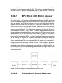
3.3.4.1
3.3.4.2
MP3 Shield with 8 Ohm Speaker ....................................................... 29
Piezoelectric Sound Generator .......................................................... 29
ii
3.3.4.3
3.3.5
Battery ....................................................................................................... 32
3.3.5.1
3.3.5.2
3.3.5.3
3.3.6
3.3.7
Global Positioning System ................................................................. 36
Wi-Fi Positioning Systems ................................................................. 38
Multilateration ..................................................................................... 38
Possible Architectures and Diagrams .............................................................. 39
3.4.1
Hardware Block Diagrams ......................................................................... 39
3.4.1.1
3.4.1.2
3.4.1.3
3.4.2
3.4.3
4
Collar Battery ..................................................................................... 32
Puppy Pal Battery .............................................................................. 33
State of Charge .................................................................................. 34
Motion Detection ........................................................................................ 35
Location Detection ..................................................................................... 36
3.3.7.1
3.3.7.2
3.3.7.3
3.4
Electronic Dog Whistle Circuit ............................................................ 30
Ball Block Diagram ............................................................................. 39
Base Charging Station ....................................................................... 40
Collar.................................................................................................. 41
Remote Control Diagram ........................................................................... 42
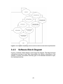
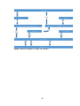
Software Block Diagram ............................................................................ 43
Project Hardware and Software Design ................................................................. 45
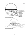
4.1 Initial Design Architecture and Diagrams ............................................................. 45
4.1.1
4.1.2
4.1.3
4.2
Mechanical Subsystem .................................................................................... 51
4.2.1
4.2.2
4.2.3
4.3
Rotational Motion ....................................................................................... 45
Mobile Center of Mass ............................................................................... 47
Hybrid ........................................................................................................ 50
Design ....................................................................................................... 51
Motors........................................................................................................ 53
Enclosure................................................................................................... 55
Motor Control Subsystem ................................................................................. 56
4.3.1
4.3.2
Design ....................................................................................................... 56
Hardware ................................................................................................... 57
4.3.2.1
4.3.2.2
4.3.2.3
4.4
Gyroscopes ........................................................................................ 57
Accelerometers .................................................................................. 59
Encoders ............................................................................................ 60
Microcontroller.................................................................................................. 61
4.4.1
4.4.2
Pin Settings ............................................................................................... 62
Algorithms.................................................................................................. 63
4.5 Remote Control Mode.......................................................................................... 63
4.5.1
4.5.2
4.5.3
Bluetooth Module Hardware ...................................................................... 64
Android Device .......................................................................................... 67
Android Application .................................................................................... 67
iii
4.5.4
4.5.5
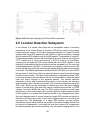
4.6
4.7
Location Detection Subsystem ......................................................................... 69
Motion Detection Subsystem............................................................................ 71
4.7.1
4.7.2
4.8
Algorithm ................................................................................................... 68
Detailed HC-05 Schematic ........................................................................ 68
Collar ......................................................................................................... 71
Base Charging Station ............................................................................... 72
Power Systems ................................................................................................ 74
4.8.1
4.8.2
4.8.3
Collar ......................................................................................................... 74
Base Charging Station ............................................................................... 75
Ball ............................................................................................................ 76
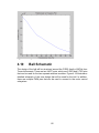
4.9 Sound Subsystem................................................................................................ 78
4.9.1
4.9.2
4.9.3
4.10
Sound System Hardware ........................................................................... 78
Sound System Switch ................................................................................ 79
Sound System Detailed Schematic ........................................................... 80
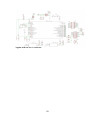
Ball Schematic .............................................................................................. 82
5 Design Summary of Hardware and Software ............................................................. 84
5.1 System Overview ................................................................................................. 84
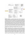
5.2 Mechanical Housing Design Overview ............................................................. 85
5.3 Software Overview............................................................................................... 86
5.3.1
5.3.2
5.3.3
5.3.4
5.3.5
5.3.6
6
Android Device .......................................................................................... 90
Collar ......................................................................................................... 92
Messaging System .................................................................................... 92
Bluetooth Communications ........................................................................ 96
Modes ........................................................................................................ 96
Environment and Coding Standards .......................................................... 97
Prototype Construction and Coding ....................................................................... 98
6.1
Parts and Acquisition ....................................................................................... 98
6.1.1
6.1.2
6.1.3
Mechanical Subsystem .............................................................................. 98
Collar Subsystem ...................................................................................... 99
Base Charging Station ............................................................................... 99
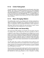
6.2 PCB Vendor and Assembly .............................................................................. 99
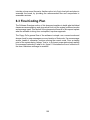
6.3 Final Coding Plan .............................................................................................. 100
7
Project Prototype Testing ..................................................................................... 104
7.1 Hardware Test Environment .............................................................................. 104
7.2 Software Specific Testing .................................................................................. 104
7.2.1
7.2.2
7.2.3
7.2.4
7.3
Puppy Pal Software ................................................................................. 104
Android Software ..................................................................................... 105
Collar Software ........................................................................................ 106
Bluetooth Software .................................................................................. 106
Hardware Specific Testing ............................................................................. 107
iv
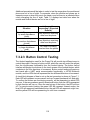
7.3.1
7.3.2
Speed Test .............................................................................................. 107
Remote Control Test ............................................................................... 108
7.3.2.1
7.3.2.2
7.3.2.3
7.3.2.4
7.3.2.5
7.3.3
7.3.4
7.3.5
7.3.6
7.3.7
7.3.8
7.3.9
Autonomous Movement Test ................................................................... 112
Durability Tests ........................................................................................ 112
Motion Detection Test .............................................................................. 114
Wireless Charging Test ........................................................................... 115
Battery Life Test ...................................................................................... 116
Dog Interaction Test ................................................................................ 117
Sound System Test ................................................................................. 117
7.3.9.1
7.3.9.2
7.3.10
Android/Bluetooth Connectivity Testing ............................................ 108
Bluetooth Range Test ....................................................................... 109
Button Control Testing ...................................................................... 110
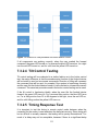
Tilt Control Testing ............................................................................ 111
Timing Response Test ...................................................................... 111
Switch Test ....................................................................................... 117
Potentiometer-Frequency Test .......................................................... 118
State of Charge Test ............................................................................ 118
8 Administrative Content ............................................................................................. 121
8.1
8.2
8.3
8.4
8.5
Budget ............................................................................................................ 121
Finances ........................................................................................................ 121
Milestones ...................................................................................................... 121
Decision Making Process ............................................................................... 122
Group Responsibilities ................................................................................... 123
Appendices ................................................................................................................. 124
Appendix A - Copyright Permissions ....................................................................... 124
Appendix B - References ......................................................................................... 126
v
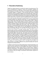
1 Executive Summary
Puppy Pal’s express purpose is to entertain the owner’s dog autonomously. This
will be accomplished by designing a device that accurately simulates the
movements and sounds of a real animal. This main device will be spherical, and
will be referred to as the Ball. The reason for choosing a ball over conventional
four-wheeled designs is durability, a fully enclosed ball allows no external
components, which could easily be chewed off by a persistent dog. The ball will be
the only device interacting directly with the dog, and all other devices will support
the function of the ball. When animals play, their movements are sporadic and they
audibly communicate. This device’s autonomous guidance system will mimic these
actions using a location detection system and pseudorandom motion sequences,
and an audio subsystem will generate intermittent animal sounds. The ball should
not wander aimlessly into potentially unsafe areas, so a user definable play area
will be created using a base station and the location detection system. The base
station will also act as a wireless charger, and will be referred to as the Base
Charging Station. In order to avoid this toy becoming a nuisance, the device should
be able to intelligently adjust its state when the dog is awake and ready to play,
and when the dog is sleeping and doesn’t want to play. This function is very
important to avoid exhausting and annoying the dog, and will be implemented in
two subsystems. The first system will be a collar attachment worn by the dog,
which will determine when the dog is moving, and signal the main device. This
device will be simply referred to as the Collar. The second system will be a
proximity sensor located on the Base Charging Station, and will be used to
determine when the dog has entered the play area. Both devices must be triggered
before the ball begins moving, because the dog should be allowed to sleep without
being disturbed while in the play area. This requires that the motion detection
systems work together to determine when the dog has gone to sleep, which will be
defined by a sharp decrease in movement, whether or not the proximity sensor
detects the dog in the play area. The sleep function will also allow an extension of
battery life. Puppy Pal should be capable of sustaining play intermittently for an
entire work day, including a one hour commute to work, eight hours at work, and
a one hour commute home. This system, the ball in particular, must be extremely
durable, as it will be exposed to outdoor weather, knocked about during play, and
even chewed on if the dog manages to catch it. The Base Charging Station and
Collar will also be exposed to elements and potential chewing, and must be
designed with matching durability.
In addition to the autonomous mode described above, Puppy Pal will have a user
interaction mode, controlled by an Android application. This function will allow the
owner to play with their dog in a more traditional sense while not requiring any
additional equipment for those already having an Android phone, capable of
Bluetooth communication. This application will allow users to control the settings
of the device, and will act as a remote control, allowing the device to operate in an
area governed only by the range of the Bluetooth communication equipment on
the two devices.
1
2 Project Description
2.1 Project Motivation
Dogs provide hours of entertainment and years of loyal companionship to their
owners, but all too often have the undesirable habits of rummaging through the
trash, digging holes, and chewing on household items. These habits are
inconvenient to the owner and can have serious health consequences for dogs,
since much of what they eat in the trash can be unhealthy and even toxic. Many
owners don't realize that the root cause of this behavior is simply boredom.
Boredom is easily prevented, but often occurs while the owner is away and thus
can become a difficult problem to mitigate. Many people have tried to give their
dog a bone or chew toy, but these quickly become uninteresting because of the
monotony and lack of feedback. These problems have been addressed by
squeaking toys, scented and flavored and countless others, but all fall short when
it comes to long term distraction. After struggling to find something capable of long
term distraction, it was concluded that only other living beings provided sufficient
entertainment. Dogs will chase squirrels, lizards and even each other, but this often
can't be accommodated in an urban household, so what better way to distract them
that with a toy built to mimic this behavior.
2.2 Goals and Objectives
The overall goal of this project is to provide all day entertainment for dogs to avoid
the destructive behaviors that boredom causes. This requires that the device be
capable of capturing the attention of the dog, and retaining that attention until the
dog is tired enough to rest. The best way for this device to capture and retain the
dog's attention is to simulate something that is already instinctually interesting to
all dogs, another animal. The simple solution of leaving another animal for the dog
to play with overlooks the tendency for the animals to play destructively together,
therefore, the best solution is to simulate an animal that will only play in a safe and
non-destructive manner. In order to effectively simulate an animal, this device
should be capable of impulsive and apparently spontaneous motion, suggesting
the need for a lightweight design and a motor capable of providing quick bursts of
movement. This product must be able to handle the wear and tear of everyday
play while still being visually stimulating, which will be accomplished through
enclosing all parts within a hard plastic sphere which will be masked with a
replaceable fabric cover. The sphere is important because there are virtually no
places that can be chewed on or torn off. The all-day duration requires a sleep
function that takes advantage of the time when the dog is napping, allowing the
dog an undisturbed rest while monitoring the dog to allow for restoration of
entertainment when the dog has woken up.
2
2.3 Project Specifications and Requirements
2.3.1
Durability
Durability plays a huge role in terms of overall specifications of the device, with the
project being produced to interact with household pets, specifically more with dogs,
the device will have to be designed to be highly durable against a wide variety of
situations that may threaten the internal electrical structure. Since dogs have a
habit of salivating on their toys, the device will have to have a spherical enclosure
that will resist any significant amount of saliva from the dog in seeping through into
the internal electronic hardware of the system. Many dogs are known to play rough
when they are put into a playful mood, they can potentially often tear and throw
around their toys that can eventually cause destruction over a period of time,
especially if there is some sort of fragile circuitry involved inside of the device. The
device must be durable enough to withstand approximately maximum impulse
forces that the dog may deliver to the system and will require the hardware inside
to stay protected in order for the device to operate to optimal standards. In addition,
the enclosure will be required to be from a material where it will be highly difficult
for a dog to chew up and expose the electrical circuit. There are a wide range of
materials that can potentially be used that may protect against the issues
previously stated. Specifically, a material that has a combination of requirements
in terms of being highly durable to the dog's habits, a low weight, and to have a
feasible rolling resistance to provide adequate mobility on carpet, tile, or wooden
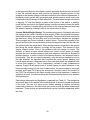
surfaces would be the most optimal choice for a plastic enclosure. Table 2.1
provides informational specifications on different types of plastics that can be used
as an enclosure for the device.
Plastic Type
Water
Absorption in
24 hours (%)
Tensile
Strength
(PSI)
IZOD
Impact
(ft-lbs/in)
Compression
Strength
(PSI)
Acrylonitrile
Butadiene
Styrene (ABS)
0.3
6500
7.7
6750
Polycarbonate
0.2
10,500
12.0 – 16.0
11,000
Acrylic
0.2
10,000
0.4
17,000
Table 2.1 Plastic specifications [1] [2]
As shown in the Table 2.3.1, all the elements are approximately equal in terms of
water absorption. Which the numerical range of 0.2 to 0.3 percent would be a
logical value, because the device is not intended to be exposed to any sort of liquid
for a long periods of time. Ideally, the device is expected to interact with a low
volume of liquids, such as saliva, throughout the day. Tensile Strength (material
breaking under tension) may be neglected depending on the dog, due to the
enclosure being spherical and with dogs having limited physical capabilities in
3
pulling on the material, but can be looked at as a guideline in making a final
decision on choosing an enclosure. IZOD impact (amount of energy a material can
absorb before it breaks) and compression strength (material breaking under
compression) are significant specs to look at because the device will primarily be
in situations where the material is compressed and additionally required to resist
impact from a dog or if the device hits a wall or falls down some stairs. The device
can potentially be put in a position where the dog is laying on it, under these
circumstances, the most reliable enclosure would have to be determined based on
the best compression strength with respect to the average maximum weight of all
household species of dogs.
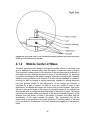
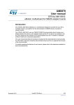
2.3.2
Mobility
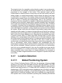
Movement inside a small space is a key priority. As mentioned in the section
above, if the dog gets a hold on to the device, it will be easier for the animal to
destroy. The primary goal in terms of mobility is not necessarily in terms of high
speed or quickness, but more along the lines of the system evading or engaging
the dog. The purpose of evading the dog will give the device a lower chance of the
dog destroying it and also it will keep the dog engaged and occupied. The velocity
of the system would be significant enough to evade the dog in a small area such
as a room in a house, thus the motors would provide enough torque to cause
rotational movement of the spherical enclosure and cause significant translational
movement of the center of mass of the device at this suggested velocity.
Theoretically, that is neglecting any internal power losses, to determine an optimal
torque range to cause the device to move will require many mechanical equations.
Ideally, the suggested velocity can be used to conclude how much current will be
needed to drive the motors. The device will primarily be used in a household or an
apartment, it will be designed in order to move swiftly and thoroughly across
carpet, tile, or a wooden surface of some sort. Depending on the material of the
floor, the speed of the device will vary, especially on carpet where the coefficient
of friction and rolling resistance will be significantly higher in comparison to the tile
and wooden flooring. For optimal mobility, it is safe to choose the material and
torque needed, assuming it will be designed to be used on carpet.
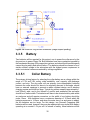
4
Figure 2.1 Free-body diagram of device
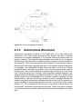
2.3.3
Autonomous Movement
Autonomous movement is critical to the Puppy Pal. It is a key feature that
separates it from other similar devices like the Sphero. The point of having
autonomous movement capabilities is to simulate human movement while no
human is present. This keeps the dog entertained even while no one is present.
The best way to simulate this is to allow the users to program their own modes into
the Puppy Pal. This is done through the Android device. Users should be able to
draw a path in the Android program and send it to the device through a sequence
of messages. The embedded software should be able to hold a list of these
predefined paths, and when the system is set into autonomous mode, either a
specific path is run or all the paths are cycled through at a rate that is set by the
user. There should also be a “random” mode that makes random changes to the
systems speed and direction in predefined intervals of time. All of these modes
should be able to be commanded into by sending a specific message from the
Android device. The user should also be able to send a message that lets the
system know which autonomous settings should be set next time the system is to
go into autonomous mode, either again by the user or by the dog’s collar system
setting it off. The movement of the device is to stay within a certain limit of its
surroundings. This plane is known as the “play area.” When the system is running
in a random autonomous mode, it should not go outside the boundaries of the play
area.
5
2.3.4
Remote Control
A secondary mode, when the system is not autonomous, will be under user control.
This will provide the user a manual override, in terms of controlling the device. The
system will need to be interfaced wirelessly to an Android device either by
developing a simple application for the user to use or using some type of serial
interfacing software to send data to the MCU. The Android device will retrieve
inputs from the user. The goal of the remote control option is to give the personnel
a simple way of controlling the system by sending commands via a wireless signal,
which will be translated in to instructions to the microcontroller to update how the
motors in the system will operate. The system will need hardware to accept the
user signal and then transitioned into the system processor. Since this device is
intended to function in a house, an RF signal that can be implemented in short
distances can be used, such as Bluetooth. Using Bluetooth will a simple way to
interface an Android device to the main system. In a basic perspective, the user
input will designate the android device to send out a limited number of signals: a
signal to turn on device, a data signal to move forward, a data signal to move
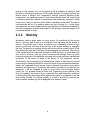
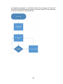
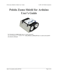
backwards, and two signals that determine right or left turns. Figure 2.2 illustrates
a simple block diagram of remote control application of the device.
Figure 2.2 Simple Block diagram illustrating RC control for device
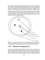
2.3.5
Wireless Charging
Puppy Pal requires wireless charging in order to allow for a fully enclosed,
physically secure device with no external components or connections which could
be destroyed. The key factors affecting design of this subsystem are size and cost,
6
power rating, and range from charging coil to receiving coil and the efficiency over
the range. Components used in the wireless charging subsystem will be either
certified or compatible with the Qi Version 1.1 standard from the Wireless Power
Consortium (WPC), where applicable, in order to create a more robust design.
WPC 1.1 defines the type of inductive coupling and the communications protocol,
allowing the receiver to be charged by any other WPC 1.1 certified charger, and
selection of components which were designed to the same specifications, to obtain
better efficiency and minimize the chance of error in the design. Power rating and
efficiency in the wireless charging module are important for lowering the charging
time as well as conserving household power, but will have minimal impact on the
system’s battery life for a given charge, therefore size and cost will be the major
driving factors. Size of the receiving coil is very important due to the positioning
constraints of a sphere, the smaller the coil, the closer it can be to the transmitter
coil, making the link more efficient. The required components for this subsystem
are a reliable and regulated power source, a wireless power transmitter connected
to a transmitting coil, a wireless power receiver connected to a matched receiving
coil and a charging module. The power source used will be a household outlet
using standard 120V AC power at 60Hz, which will be stepped down, rectified,
filtered, and regulated before being fed as DC power to the transmitting device.
The transmitting device will convert a DC power source into a wireless power
signal that can be efficiently transferred from the transmitting coil to the receiving
coil and will provide a communications link to the receiving device for control and
monitoring. The receiving device will convert the received wireless power signal to
a regulated DC output. The charging device will use the regulated DC output from
the receiving device to safely and efficiently charge the battery system.
2.3.6
Location Detection
Puppy Pal requires a location detection subsystem in order to keep the dog safe,
if Puppy Pal simply rolled around with no location feedback it could potentially roll
into an unsafe area like a road, or undesirable area, like the pantry. The location
must be capable of working with the control and mechanical subsystems to keep
Puppy Pal within its assigned area of play within normal circumstances, meaning
it is not being forced out by an external force. The location detection subsystem
should also be capable of guiding Puppy Pal to return to its area from any place
that the mechanical subsystem is capable of doing so, after it is carried off course
by an error or external force. The key factors of the location detection subsystem
are accuracy, precision, size, complexity of implementation, additional hardware,
and cost. The location detection subsystem must also be capable of accurately
providing velocity data, or primary data must be accurate and be updated
frequently enough that velocity can be derived from the position data source. This
subsystem must be able to provide location measurements accurate and precise
enough to keep the device within a defined radius of the charging station. The
location subsystem must be capable of operating inside a building without a clear
view of the sky as well as outside without Wi-Fi access. In order to achieve an
accurate guidance system, the data produced by the location detection system
7
must be simple enough to be processed in time to accept the next batch of data
and for the data to still be accurate, or have a method for accounting for the
distance travelled during processing time. In the interest of minimizing the
complexity of integrating the location detection subsystem, a fully functional
module would be ideal. Possible technologies to be researched and considered
are a Global Navigation Satellite System (GNSS) such as the Global Positioning
System (GPS) in the United States, Wi-Fi Position Systems (WPS) for use of the
device in buildings or areas without a clear view of the sky, an Inertial
Measurement Unit (IMU) with a software implementation of a Kalman Filter, and
multilateration systems using electromagnetic, ultrasonic, or infrared sensors. In
addition to these standalone systems, hybrids and augmentation systems will be
considered.
2.3.7
Motion Detection
The primary need for a motion detection system arises from the need to keep the
dog occupied at all times while awake without becoming a nuisance when the dog
is sleeping, however, this system will also enable an intelligent sleep mode to
extend battery life. The motion detection subsystem must be capable of
independently determining when dog is awake regardless of proximity, within the
limitations imposed by the communication subsystem, and when a dog is within
the region of play. The requirement of determining that the dog is awake suggests
that this device be located on the dog, and thus will require a communications
system to relay information to the main processor on the ball. This device will be
attached as a collar and must be of minimum size in order to avoid causing
discomfort. This system will have to intelligently discriminate between a dog
adjusting while sleeping and a dog that is fully awake, to avoid irritating the dog.
This subsystem must also determine when play is over, to enable sleep mode and
allow for longer battery life. The requirement for determining when a dog is within
the play area means that this subsystem could be located either on the ball or on
a separate device. Placing this device on the ball imposes complications because
the ball is not always located at the center of the play area and is not always
oriented the same way, however, placing this system on the charging system can
eliminate both of these issues. This now means that the charging station will also
require a communications subsystem to relay information to the main processor
on the ball. Since this device is intended for use both indoor and outdoor, any
sensors, particularly infrared or optical sensors, must be capable of properly
functioning in full view of the sun. Factors important in choosing components for
the base charging station’s motion detection subsystem will be the range of
detection, the method of detection and experimental effectiveness, and its cost.
2.3.8
Sound Projection
Once again as stated previously, a specification of the device is to keep the dog
engaged; a way of doing that is implementing a sound projecting subsystem to
8
attract the animal to the device. A simple way of looking at it is, if the dog is at a
far distance from the device, the system processor will turn the output connected
to the sound projection subsystem on to play a brief sound clip to grab the attention
of the dog. The sound system will be triggered by a motion sensing system that
will measure the activity of the dog, for example if the dog has a consistency of
movement and is appeared to be active, the sound will be activated to lure the dog
towards the device. However, if the sensor reading displays inactivity it will assume
the dog is laying down or sleeping which results in the sound clip not being played.
The sound system can be either a small speaker that can have specific sounds
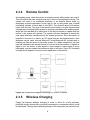
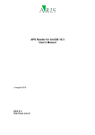
downloaded into it or a piezoelectric sound generator. As shown on the block
diagram in Figure 2.3, the MCU output pin is connected to the input of the speaker
or sound projection device; the microcontroller output is triggered high if the motion
sensor reads in a threshold value that represents consistent movement by the dog.
A high output voltage turns on the sound generating device to attract the dog.
Figure 2.3 Simple Block diagram illustrating sound projection control
2.3.9
PCB
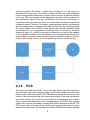
The device will need three PCB’s; one for the main system that will be placed in
the actual ball, one for the charging station, and another smaller one that will be
placed on the collar of the animal. The PCB located in the ball will provide the main
control of the entire system that will communicate with all of the other subsystems
and will be used for motor control, sound projection, receiving data from Android
device, and location detection from the charging station. The PCB on the charging
station will be control the wireless charging and location detection of the ball. The
PCB on the collar of the dog will be used to send a signal when there is motion
detected from the animal. The hardware for all three PCBs will need three separate
9
MCUs and three power sources to operate. The PCB in the ball will be powered
by a rechargeable battery, which will need to be able to function coherently with
the wireless charging hardware. The battery in the ball will be required to have
enough power to operate two motors that will move the device. The charging
station PCB will be powered by an AC voltage supplied from the wall socket (will
be rectified to around 5 to 12 V). The PCB on the collar will be powered by a low
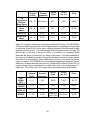
voltage battery, a table displaying all the basic specifications of all three PCB’s are
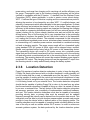
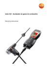
shown below on Table 2.2. A simple block diagram is illustrated to show a visual
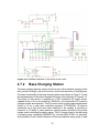
representations of the placements of the three PCB in Figure 2.4.
PCB Location
Charging
Station
Enclosure
-Motor Control
-Operate Motor
-Android
Communication
-Sound Projection
Functionality
-Location
Detection
(Receive Location)
-Motion Detection
(Receive
Detection)
DC Voltage -12 to
Power Supply
24 V
(Rechargeable)
Table 2.2 Specifications on each PCB.
Collar
-Wireless
Charging
-Location
Detection
(Transmit
Location)
- Motion
Detection
(Transmit
Detection)
AC Voltage -120
V
DC Voltage- 3.3
to 5 V
Figure 2.4 Block Diagram illustrating PCB locations of entire system
10
3 Research Related to Project Definition
This project’s design and construction demands specialized knowledge and
experience. In order to build the best possible toy, the group’s body of knowledge
must grow. Different techniques were studied and compared to decide what
methods will work best in the design of Puppy Pal.
3.1 Existing Similar Projects and Products
To point research in the right direction, projects similar to the initial concept of
Puppy Pal had to be studied. These were used to learn what modes of
transportation and control were used, what had been successful, and what could
possibly be accomplished within the required timeframe. The most important
knowledge gained was the scale of the project; the project’s objectives could be
met.
3.1.1
Sphero
Sphero is a robotic ball toy. Owners control the toy’s motion and the LED color
displayed with a smartphone application. Sphero uses Bluetooth communication
to receive its commands. It can also charge wirelessly. To track movement, a
three-axis accelerometer and a gyroscope were installed.
In addition to the basic control app, Sphero’s creators developed a series of
programming environments to encourage Sphero owners to be creative and make
their own apps. The apps range from setting a path for Sphero to follow to an
augmented reality racing and zombie fighting games.
Puppy Pal will recreate the spherical shape, wireless charging, and Bluetooth
communication features Sphero has. The great variety of apps developed for
Sphero shows that there are many applications for this type of toy. Making Puppy
Pal autonomous does not seem so far-fetched.
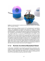
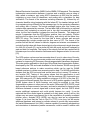
In Figure 3.1, the insides of Sphero are displayed. This gives insight to the structure
of Sphero. The wheels (part B) drive the ball to roll. The top slip bearing (part C)
braces the structure, keeps the wheels from slipping, and helps to keep the internal
structure parallel to the ground. This mechanical design is a possible solution to
driving Puppy Pal.
11
Figure 3.1 shows the inside of Sphero and the assembled Sphero in its charging
dock. Permission Pending.
Sphero’s Android app interfaces are built off of a development kit provided by
Orbotix. The development kit provides many Bluetooth routines for sending
commands compatible with the Sphero. User interfaces are completely up to the
developer however. There have been numerous designs for controlling the Sphero
from a cell phone, most modeled off of old video game and RC car controllers. One
very popular approach is to have the forward/backward and left/right control
independent of each other. Probably the most used method of control is to provide
an object to move around across a two dimensional plane. Moving the object
directly up the y-axis would make the Sphero go forward, and moving the object
into quadrant II would make the Sphero go left, and so on. This approach proves
to be the most intuitive and easiest to use because of its simple design its onefinger usage. This is the GUI that Puppy Pals Android software will try to mimic.
Aside from movement, apps also have the ability to control the LEDs inside the
Sphero. Puppy Pal only has two LEDs and they are for debugging purposes for
their will be no need to control them from a user's standpoint.
3.1.2
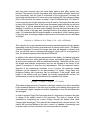
Remote Controlled Basketball Robot
In this project, a basketball moves along the ground based on input from a twochannel radio and receiver. Inside of the basketball, a hamster ball holds the
chassis. The sides of the chassis are attached to the outside of the ball. This holds
the chassis in the middle of the ball. A drive motor, servo, and steering arm are
used for drive and steering. A gyroscope was also included.
12
The bottom of the steering arm holds the batteries and weights. With enough
weight, the chassis is kept parallel to the ground despite the ball’s motion. As the
motor and servo rotate the steering arm in the desired direction, the rest of the ball
is pulled forward to keep up with the new center of mass. The gyro senses the
changes in rotation, allowing for control.
This robot’s mechanical system would be a straight forward solution to the
mechanical design of Puppy Pal. The main obstacles of this design are the weight
used, the construction or purchase of the chassis, and control. The use of only a
gyroscope in this project left much to be desired in precision. Puppy Pal could
include an accelerometer to achieve a more clear-cut sense of maneuverability
than the basketball robot.
3.1.3
Segway
The Segway balances on two wheels using a system of sensors to follow the rider’s
center of gravity. Five gyroscopes and two tilt sensors are used to detect the rider’s
movement atop the Segway. This information is used by the transporter’s control
circuits to decide on the proper course of action: going forward, turning, stopping,
or sitting still. If the mechanical system uses changes in the center of gravity to
drive movement, Puppy Pal will incorporate its own system of sensors to decide
which direction is best and to balance quickly when sitting still. The Segway shows
that such a system with built-in redundancies can be effective.
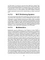
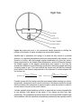
Figure 3.2 shows the forces acting on the Segway and its rider. As the rider moves,
Segway uses the data from its sensors to find what action will keep the rider
balanced [3]. Unbalanced forces create toque and result in falls and injuries. Puppy
Pal will need to do this as well. It will also use data from the dog’s collar to decide
how to interact with a dog when in autonomous mode.
13
Figure 3.2 The balance of the forces acting on a Segway and its rider when
stationary, accelerating, cruising, and decelerating. Reprinted with permission
from Brian Hughes.
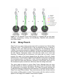
3.1.4
Stray Pooch
Stray Pooch is a senior design project was built by students from Wichita State
University in 2011. This project’s goal, to be an interactive dog toy, is similar to
Puppy Pal. Their robot was built using a hamster ball. The mechanical system
consists of two motors connected to a gearbox. Shafts are connected to the motors
and the sides of the ball. As the motors rotate, the sides of the ball rotate and drive
the ball forward. Framework inside of the ball was made out of wood and
aluminum. Combined with the electronics, the frame was too heavy to work
properly; the center of the frame dragged along the bottom of the ball, slowing
down the robot. This shows that weight must be watched closely when constructing
the mechanical portion of Puppy Pal. In their follow-up experiments, the Wichita
group rebuilt the frame with aluminum. Aluminum is much lighter than wood, so
the mechanical system worked more efficiently when the change was made.
This group used an Arduino to control Stray Pooch. Although there are many
tutorials available for Arduino applications, the group’s lack of experience made
the coding part of the project very difficult. The Puppy Pal group members will
combat the challenge of inexperience with teamwork. For wireless communication,
Stray Pooch used XBee modules. They communicate with other Arduino devices
that contain a XBee module in serial. Their success with this method could be
applied to the Puppy Pal’s wireless communication system.
14
3.2 Relevant Technologies
3.2.1
Autonomous Robotics
There are plenty autonomous robotic systems in use today. Many are far more
sophisticated than the Puppy Pal device will ever need to be, but there are plenty
of ideas to take from these robots that can be integrated into the project. A popular
autonomous robotic system is iRobot’s Roomba, which is designed to clean a room
by itself and find a path back to its “home base.” There are a number of sensors
on the device to help it perform this goal, some of which are an infrared receiver,
bumpers on either side of the front, and a number of “cliff sensors,” which are
actually just more IRRs pointing down and checking the time difference between
the signals bouncing back. The Roomba has a fairly trivial cleaning process. It
typically starts out doing circles until it hits something, which it assumes is a wall,
and tries to follow its contour. By making slight adjustments either left or right, if it
finds that it has hit a wall after a few turns, it makes a major turn, usually around
180 degrees, and goes in a straight line until it hits another object, and repeats the
process of trying to follow its contour. It’s a fairly simple loop that utilizes all
available sensors on the device. Where the true brains comes into this product is
its ability to find its way to its charging station. This is something that the Puppy
Pal tries to directly mimic. From a top down perspective, the Roomba is circular
with a “front” and “back” designated by bumpers on the left and right. There are
four infrared sensors on the front, back, left and right sides of the device. The
Roomba home base also has an infrared emitter on it and when the Roomba needs
to get back, it uses time difference of arrival (TDOA) to know which way to turn,
takes a little move forward, and then does the same thing over again. Using this
technique, along with the bumpers and wall detection, the Roomba does some
crude path finding back to its charging station. There’s a lot to be learned from this
example, but the Roomba’s physical dimensions are much greater than that of the
Puppy Pal device. In other words, TDOA is significant with the Roomba whereas
TDOA on the Puppy Pal would provide almost no difference, and the small
differences would have to be accounted as error because of their sporadic
changes.
There are other autonomous cleaning robots that achieve mostly the same effect
which include the Neato XV-12 and Mint Plus. Aside from different detection
features and shapes, these devices act in much of the same way as the Roomba.
Urbie, the Urban Robot from NASA could also provide a lot of inside to the Puppy
Pal because of its ability to maneuver in any kind of environment. The design of
Urbie is much more involved than the Roomba because it is specifically designed
to go over rough terrains and even up and down small steps. Another unique
feature of Urbie is that it contains two cameras to provide feedback of its
surroundings. This also helps create a stereoscopic view of it location to help it
avoid obstacles in its path. Because of Urbie’s “car-like” appearance, many
15
mechanical arms with capabilities of 360 degree rotation project from the top of the
robot to help it flip upright in the case that it gets turned over. Although not in the
same sense as Urbie, the Puppy Pal’s inside can become turned over, however
because of its enclosure no mechanical arms would aid the device in turning over.
Instead the device naturally turns back over upon movement after it has become
flipped. Moreover, it is not unnatural for the device to periodically spin around while
inside its spherical housing.
A far newer and more advanced robot from NASA is the Mars rover Curiosity.
Much like the Puppy Pal, the mars rover is controlled as well as autonomous when
need be. This implies that it also has a messaging system, albeit much more
sophisticated, much like the Puppy Pal. The autonomous capabilities are second
hand compared to being controlled from Earth. Because of its extreme distance
from its controllers, Curiosity sends data through ultra-high frequencies around 400
MHz. Occasionally the rover sends data directly to earth at a rate between 3.5
Kbits to 12 kbits. More often than not there is an orbiter that acts as an intermediary
between the two. It is in scope of the rover for about eight minutes, and in that time
sends about 60 Mbits of data. Puppy Pal would not be capable of making use of
all that data, but using an orbiter as an intermediate object did give new ideas to
the way that Puppy Pal would be controlled. By having the charging station have
its own processor and Bluetooth module, it could pick up on any Bluetooth
messages being sent out, namely any message commanding the wheel speeds.
This would allow the base station to keep a decent track of where the Puppy Pal
is at any time, and allow it to navigate the device back to a close range of the
charging station. From there more accurate device could allow precision docking
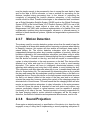
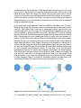
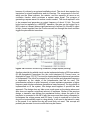
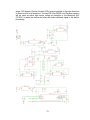
to begin charging. Figure 3.3 shows the similarities between the data flow of the
orbital and the Puppy Pal device, assuming this paradigm was chosen.
Figure 3.3 Similarity between Curiosity and Puppy Pal’s communications
It is essentially the same, except that messages being sent from the Android
16
device to the Puppy Pal are intercepted by the charging station rather than sent
directly to it.
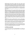
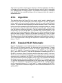
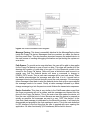
3.2.2
Android Remote Control Applications
There are many devices and projects that have integrated android devices into
their system. In terms of using and incorporating Android application for the Puppy
Pal, the Android device will be used solely as a remote controller, as in controlling
movement and potentially turning the device on or off. There are many techniques
to interface Android device connectivity to a MCU. This specific section will display
projects that use Android device integration and relevant techniques that may
potentially be referenced.
A similar project that was observed used Android interfacing to control a remote
control car [4]. The RC car’s core processing unit uses the Arduino Uno
development board with a Bluetooth module, specifically uses the HC-06, to read
in data sent from the Android device. In addition to the RC car using the Bluetooth
functionality, it also incorporates the accelerometer embedded in the Android
device. The Android application developed provided three different ways for the
RC car to be controlled: tilting control, normal button control, and touch control.
Tilting control requires no button use, the tilting motion of the Android device
designates the motion of the RC car just purely using the built-in accelerometer in
the Android device. To elaborate, if the user tilts the Android device forward, then
the RC car will accelerate forward, if it is tilted backwards the car goes backward,
left and right tilts will result in right and left turns respectfully. The normal control
displays five commands on the touchscreen of the Android device for the user to
push. Each command represents a direction the RC car can move. The five display
commands represent the direction of motion, which are: forward, backwards, left,
right, and OFF. Touch control displays a reticle in the middle of the display on the
Android device, this reticle is representative of the RC car. If the user wants to
move the RC car using touch control, the user will have to drag the reticle in the
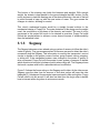
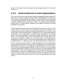
direction of desired movement of the RC car. Figure 3.4 illustrates the three control
options.
17
Figure 3.4 Illustration of three Android control methods: A) Tilt, B) Button, C)
Touch.
The RC car project uses the CxemCar 1.0 Android application developed in the
Eclipse IDE. The version of the Android device must be greater than 3.0 in order
for the application to control the motors. The Android device is configured to the
Bluetooth module on the car by connecting and searching for the module in the
Bluetooth settings on the Android device. The CxemCar application uses the MAC
address of the Bluetooth module to directly connect to the RC car, which finalizes
a wireless serial connection between the two hardware devices, and data can be
sent using the UART functionality on the Arduino Uno. The CxemCar application
has many settings that can be configured. The application can edit the output
characters representing a specific direction of motion the user can send to the
Bluetooth module, changing the accelerometer sensitivity from the Android device,
editing the maximum/minimum values on right/left PWM values, and other settings
that can be configured.
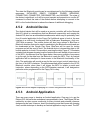
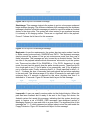
Another similar project designs a home automation system using Bluetooth [5].
The basic idea of the system is to control devices such as lights, air conditioning,
fans, and other around the home products that are limited to an ON/OFF
functionality using a mobile device. The project reads in data from a HC-05
Bluetooth module. Unlike the RC car project as previously stated, the home
automation system uses an Android application called BlueTerm, which is an
emulator for serial devices that use Bluetooth to communicate between the system
and the Android device. A user can use BlueTerm to directly send data to the
module for the system processor to read in. The items that the user wants to control
will be connected from the PCB to the relays of those items. Each item that the
user wants to control, specified in the MCU coding, will have a specific output pin
and an assigned ASCII character affiliated with it to either turn it on or off. The
BlueTerm application allows the user to send the specific ASCII character directly
to the MCU in order to control the connected device. This project shows a method
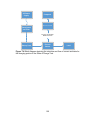
in connecting the Android as a controller to multiple devices. Figure 3.5 provides
18
a block diagram on how Android devices can be connected to multiple devices or
systems that can be controlled within a household.
Figure 3.5 Block Diagram illustrating Android control over multiple systems
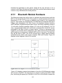
3.3 Strategic Components
3.3.1
Wireless Communications
There will be three wireless communication systems that will need to be
implemented into the entire system. For example, there will need to have a method
of wirelessly communicating between the ball and the Android device, the ball and
the charging station, and the ball and the collar that the dog will be wearing. Ideally,
the ball and the charging station will not exceed a significant difference in distance,
however the distance between the collar and ball may vary. Since there are three
different wireless applications that will be implemented in the system, potentially
there can be multiple different components of wireless hardware modules that may
be integrated into the system depending on functionality. For example, a GPS
module can be used for location detecting, a Bluetooth module for an Android
serial connection, and ZigBee hardware for reading input from accelerometer then
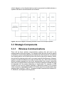
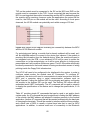
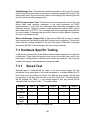
sending data to the MCU. Table 3.1 compares simple characteristics between WiFi, Bluetooth, and ZigBee technologies [6].
19
Technology
Wi-Fi
ZigBee
Bluetooth
Data Rate
2-11 Mbs
1 Mbs
0.25 Mbs
Range
100 m
10-100 m
10-30 m
Large data
transfer at high
speeds
Remote control,
Sensor data
Android
connectivity
Applications
Power
Consumption/
High
Low
Cost
Table 3.1 Wireless Communication Comparisons.
3.3.1.1
Medium
Wi-Fi
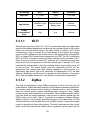
Observing the data from Table 3.3.1, Wi-Fi can potentially supply the largest data
transfer at the highest speeds and can give the user wireless control of the system
without the user and device being in the same vicinity. In addition, Wi-Fi would
potentially be a way to connect the Android device to the system and retrieve
access to GPS capabilities on the mobile device. If the using Atmel’s ATmega328P
MCU, an Arduino Wi-Fi shield can be plugged into the PCB. The Wi-Fi shield uses
WEP and WPA 2 encryption security protocol and the Arduino provides a Wi-Fi
library to simply connect to a network [7]. However, Wi-Fi requires the most power
and is more costly in comparison to the other technologies. If possible, Wi-Fi may
potentially be implemented in the base charging station, as providing power will
not be an issue. The overall system does not necessarily need to run any
applications that require large data transfer capability or data transfer at a
significantly high speed. Due to the complexity of implementing Wi-Fi, the best
approach would be to use Bluetooth to integrate an Android device to the system
and to use the ZigBee standard for other wireless communication applications.
3.3.1.2
ZigBee
The clear cut advantages of using ZigBee technology is that it is low cost and it is
power efficient. ZigBee hardware is perfect for short distance wireless applications,
for example using remote control, reading in wireless sensors, and monitoring.
Since the system doesn’t require transferring large amounts of data, ZigBee
modules are an ideal candidate to be interfaced. Since ZigBee products can be
used with small low voltage batteries, it can be used to transmit signals from the
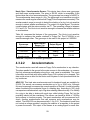
PCB located on the collar. Table 3.2 provides a comparison between different
ZigBee modules. From the basic specifications listed on the table below, the Digi
International looks to be the ideal choice for a ZigBee module; it has a lower supply
current to transmit and lower output power. The lack of data rate and line of sight
range on the Digi International module can be neglected, as the system will not
20
require transmission of data at a high data rate and the transmitter and receiver
will operate at a close line of sight distance from one another ideally. Since the
battery on the dog collar will be designed to operate on low power, the Digi
International module illustrates the best alternative on transmitting a signal after
the accelerometer has been activated.
Brand
Digi International
(XB24-Z7PIT-004)
Atmel (ATZB-RF233-1-CR)
Frequency Band
2.4 GHz
2.4 GHz
Line of Sight
Range
120 m
1.96 km
Data Rate
250 kbps
2 Mbps
Supply Current-Tx
35 mA
157 mA
Supply Current-Rx
38 mA
7.5 mA
Supply Voltage
2.1 – 3.6 V
3V
Output Power
1mW
112 mW
Price
17.00
19.68
Table 3.2 ZigBee/802.15.4 module specifications.
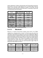
3.3.1.3
Bluetooth
Bluetooth is a wireless communication standard, which similar to the ZigBee
standard has a frequency band of around 2.4 GHz that can be used as an
application for short distances, lower power, and can be implemented using low
cost modules. Bluetooth can potentially be used to communicate between different
hardware wirelessly, in relation to the Puppy Pal, system control using an Android
device. Even though the Android device will be in a visual line of sight within the
Bluetooth module, it does not necessarily need to operate under those conditions
because Bluetooth devices use a radio communications system. Bluetooth
communications are usually divided into 3 classes in that all have their own
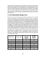
specifications with respect to power and data transmission range. Table 3.3
displays the different Bluetooth classes.
Class
Max power (mW)
Max power
(dBm)
Approx. range
1
100
20
100
2
2.5
4
10
3
1
0
1
Table 3.3 Table displaying the different classes of Bluetooth devices [8].
21
Bluetooth networks are implemented using the master-slave structure to control
data flow. To elaborate, the device that is responsible for controlling
communication data is referred to as the master, and slave devices usually just
retrieve data. Master devices connect to a maximum of seven slave devices and
can potentially communicate to them, however slave devices cannot communicate
among other slave devices. The Bluetooth network would mesh perfectly into the
Android integration of the Puppy Pal. The Android device will be the master device
and the ball will be the slave device. In addition, if there is a Bluetooth
communication method needed to transfer data to the charging station and dog
collar, then those components will be referenced to be slave devices in the
network. Figure 3.6 illustrates a simple Bluetooth network of the overall system;
the charging station and dog collar may not need to receive data from Android
device.
Figure 3.6 Puppy Pal Bluetooth Network
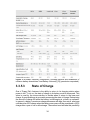
In choosing a specific Bluetooth module, many factors will play a role in a final
decision such as cost, operating voltage, size, and the complexity of interfacing
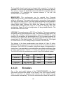
the module to the system. Table 3.4 provides a table of significant specifications
of potential Bluetooth modules. From observing the table, it appears that all the
modules require around the same operating voltage to run, with modules such as
the RN-42 with a potential 6 volt operating voltage. The largest module appears to
be the HC Bluetooth modules, with the RN-42 and the WT11i being approximately
around the same size. Looking at the signal coverage specification, once again the
HC module has the lowest standard in comparison of the other two modules with
30 feet, the RN-42 ranging from 50 to 60 feet, and the WT11i with a significant line
of sight range of 328 to 984 feet. The max data rate value for all three potential
Bluetooth modules are around the same of around 2 to 3 Mbps, with the HC
module with the lowest potential data rate. The HC-05 module will cost the least
amount, with the RN-42 and WT11i costing in the 30 dollar range. With all the
specifications looked at, the HC module would be the ideal choice of hardware in
integrating Bluetooth communication into the system. It would fit in perfect with the
system because the 30 feet signal coverage is an acceptable range for the Puppy
22
Pal; the project will operate in a house or room with the user controlling it near the
ball, so a 30 feet range is more than acceptable. In addition, the HC module can
connect to the Android device in a simple way by locating the module from the
Android and entering a given password to connect. The HC module is larger in
size in comparison to the other two, but can be negated due to the the price of the
HC module being much lower.
Bluetooth
Module
Operating
voltage
HC (06, 05)
RN-42
Bluegiga WT11i
3.3 V
3.3 to 6 V
2.7 to 3.6 V
Size
4.3 x 1.6 x 0.7 cm
38 x 17 mm
35.75 x 14.5 x 2.6
mm
Baud rate
9600
9600
Signal coverage
30 ft.
50 to 60 ft.
328 -984 ft.
(L.O.S.)
Max Data Rate
2.1 Mbps
3 Mbps
2-3 Mbps
Price
10.00
35.00 to 40.00
30.00
Interfacing
Complexity
Simple
(Password
connectivity)
Mildly complex
(requires
programming)
Mildly complex
(can be integrated
with the
ATmega328p)
Table 3.4 Bluetooth module comparison
3.3.2
3.3.2.1
System Processing
Microcontrollers
MSP430 Launchpad: The MSP430 from Texas Instruments value line is a
fantastic processor for the price. When you order the package you get two
microprocessors: the msp430G2553IN20 and msp430G2452IN20. They’re both
identical other than the internal clock speeds, but on the development board you
defunct both by soldering the external 32.768kHz crystal onto it. The tools that are
available make downloading code onto the chip very easy. The development
board’s only interface is USB, which provides power and a tunnel to the processors
flash memory to burn code in. Some of its more important technical specs are 16kB
flash memory, 512B of RAM, interruptible GPIOs, 16-bit timer, 8-channel 10-bit
ADC, and support for USCI, I2C and UART serial communications. There are also
plenty of booster packs that give the processor some extended features. The
processor runs on 3.3 volts and also has configurable low power modes, which
would be perfect for our application. The real flaw of this processor is its code
space. The processor is part of TIs value line for a reason: it’s for hobbyists to
tinker around with. There is a code expectancy of at least five times the amount
23
available, so that immediately put this one out of possibilities. Aside from that, there
is only one serial communication line. Although this could be dealt with by a little
extra effort, coding would be much easier with multiple UART lines, because there
will be multiple UART signals coming in at any time. By having only one data line
for this, messages would have to have extra details encoded in them, which would
in turn have to be decoded on the processor level. Speed is absolutely critical for
the Puppy Pal device, so it cannot afford the extra cycles this decoding would bring
along. Another area where the MSP430 shines is its community support. Virtually
every question about the processor has been asked and answered by TI, and if
not on some online forum. There are open source alternatives to Code Composer
Studio as well. GCC has a package that supports compiling, linking, and loading
of MSP430 programs through the USB interface. There are also plenty of
command line tools that allow memory and register dumps of running programs.
GCC also provides a C++ compiler, but the limited code space on the chip makes
this option impractical. Below is a summary of the pros and cons of the MSP430
Launchpad. Table 3.5 shows a summary of the pros and cons of the MSP430.
Pros
Cheap, great community support, open source alternatives to all software
Cons Slow speeds, limit flash and RAM memory, C++ isn’t practical, limited
serial communications
Table 3.5 Summary of MSP430 pros and cons
ATmega328P: The ATmega328P comes from Atmel corporation and has many
useful features for the Puppy Pal device. As far as its physical size, the processor
is quite small, with dimensions of about a square half-inch. It has 24 GPIO pins,
and 8 more dedicated to specific features, two being a two-line UART interface.
One of its best features is that it runs on 1.5 - 5.5 volts. This comes in perfect for
low power modes which the Puppy Pal device heavily takes advantage of. All 24
of the GPIO pins are interruptible which is nice, but a bit overkill. It has 30kB of
flash memory, 2kB SRAM and 1024B of EEPROM. Much like the MSP430, the
memory statistics just aren’t enough for our code. Furthermore, the community
support and 3rd party tools are slim to none with this device. With the time
constraints we are facing, the overhead of not being able to find exactly what we
need in the case of an emergency turned this part away. Last, and probably most
detrimental, is that the processor is part of the AVR 8-bit series. Because Puppy
Pal is going to be very math intensive, 8-bits for calculations would not cut it.
Although clever techniques allow complex computations to be done with 8-bit
devices, there were better processors for similar prices out there. Table 3.6 shows
a summary of the pros and cons of the ATmega328P.
Pros
Cheap, plenty of interruptible pins, operating voltage of as low as 1.5V
Cons Slow speeds, 30kB flash, 2kB RAM, poor community support, only 8-bit
Table 3.6 Summary of ATmega328P pros and cons
24
LPC2148: The last microcontroller we considered was the LPC2148 by Philips.
This is as beefy as a processor can get for small embedded system. It’s part of the
ARM architecture suite, and offers a 32-bit RISC instructions set. The chip is
physically small and powerful, with tons of features including but not limited to
512kB of flash, 32kB of RAM, 2 10-but ADCs with 14 channels a piece, a full speed
USB 2.0 Speed Device Controller, 2 UART, I2C and SPI interfaces, a PWM unit,
and a 60mHz processor with an on-board crystal oscillator to top it all off. All of
these features are perfect for the Puppy Pal device: plenty of code size, plenty of
RAM, two UART channels, and a PWM unit. The PWM unit comes in especially
handy because of the constant change to our duty cycle to get the wheels to spin
at certain rates. Aside from the Hardware, there is decent community support and
a very detailed users guide that goes over all of the features the Puppy Pal device
will use. It comes standard with a C and C++ compiler, and because of the flash
size, for the software running on the device many useful features of the C++
language can be taken advantage of, like operator overloading and virtual function
tables. The processors main interface to embed code is through I2C. There are
also no development tools available that make the process of writing, compiler and
loading easy. This is also a processor for very large-end embedded systems. In
other words, there are many peripherals this processor is designed to handle, like
external memory and network interfaces. Though it doesn’t really harm anything
on the Puppy Pal device, it would be that much more overhead to disable all the
features that weren’t go to be used. This package is nearly flawless other than that,
and the only reason it was not chosen is because it was unfamiliar territory
compared to the last option. Table 3.7 shows a summary of the pros and cons of
the LPC2148.
Pros
Cheap, 512kB flash, PWN unit, C++ support, 60mHz
Cons Unfamiliar territory, extra unneeded peripherals
Table 3.7 Summary of LPC2148 pros and cons
TMS320F28069MPN: TI has quite a few options for microprocessors. Even more
so, there different lines of processors have different options you can filter out to
get exactly what you’re looking for. In doing so, the TMS320F28069MPN from the
C2000 series was found. For roughly the same price as the LPC2148, this 32-bit
processor comes with a 90Mhz master clock frequency which will come in very
handy for transferring, receiving and decoding messages. There is also Control
Law Accelerator that supports 32-bit floating point operations that are done
independently of the main CPU. In addition to those features it contains 256kB of
flash, 96kB of RAM and 2kB of OTP ROM. This processor runs on 3.3V and comes
with two different types of low power modes that can be used for when the Puppy
Pal device is in either its charging or waiting state. Some other useful features are
a Peripheral Interrupt Expansion block that supports interrupts on all peripherals,
3 32-bit timers, 8 pulse width modulation units, 16 channels of 12-bit ADC with a
conversion time if 286 nanoseconds, 2 UART and SPI modules, and 40 GPIO pins
25
with input filtering. Aside from reliability, Texas Instruments products are also
known for their great documentation and community support. The C2000 series is
no exception. Their website is full of example code and schematics to ease the
processes of design for common products. One of the nicest features of the C2000
series is the inclusion of the instaSPIN modules. This is a library of products that
aid in embedded system motor controlling. The software is specifically for
controlling devices from a computer and not to be run directly on the embedded
system so it cannot be used for the final product, but it will be incredibly helpful for
the early stages of development when simple testing of the two motors needs to
be done. There are plenty of breakout boards for this chip as well. The
development platform most commonly used for this product is Code Composer
Studio. It has version for both Windows and Linux and interfaces nicely with
development board. It handles all compiling, linking and downloading of code to
the board. It has full support for C++, and because of the code space on the chip
all of its features can be utilized. Much like the LPC2148, the chip also comes with
a lot of extra peripherals that will not be used. For instance, the I2C interface will
have no use and just be an extra pin on the board, but this is much like 35 of 40
other GPIOs that will not be used. This is a true embedded processor, so the
hassle of disable features in code is not a problem; if they’re not needed they will
just not be used, unlike in the Philips alternative. Table 3.8 shows a summary of
the pros and cons of the TMS320F28069MPN.
Pros
Cheap, 256kB flash, 96kB ROM, PWN units, full and code-efficient C++
support, 90mHz, great community support, familiar territory for all
members, 2 UART lines, instaSPIN technology
Cons Extra unneeded peripherals
Table 3.8 Summary of TMS320F28069MPN pros and cons
3.3.2.2
FPGA
FPGAs are another alternative to a pure microcontroller project. Although FPGAs
are not typically used for projects like this, they do carry some advantages to them
that would prove to be useful for the Puppy Pal device. For one, FPGAs focus on
concurrency. This would give us much more precision on our ISRs because we
could get into detail about how long they should take. With that being said however,
the code design currently only has one statement executing in our ISR so this
doesn’t help us out much. Secondly, FPGAs are extremely flexible, but this comes
at a hefty cost. You have the unique ability to create virtually any platform you want
with these devices, but the overhead of having to create them is not worth it for
this project. When talking about microcontrollers, the hard part of choosing a chip
is sorting through all of the different options that each provides. The ability to add
and remove features as needed provides a huge advantage when working with
FPGA. Unfortunately, you must use a HDL to go about doing this. Another
consequence of FPGAs is that they consume much more power than
26
microcontrollers, and there are typically no optional low power modes to choose
from. Furthermore, FPGAs do not handle serial communications as well as
microcontrollers. Serial communications is one of the most vital operations of the
Puppy Pal and could not function without it. FPGAs are a great option for many
projects, but in the case of small embedded systems the overhead they come with
is not worth the risk.
3.3.3
Motors and Actuators
Mobility and maneuverability are two of Puppy Pal’s features. Motors are required
to initiate movement and to choose the direction the device will go. The types of
motors chosen will meet the needs of the mechanical design without hindering
speed, steering, or power. The actuators used would also meet these criteria.
3.3.3.1
DC Motors
A DC power supply is the most practical source for this project. This means the
use of DC motors are preferable to AC. They use less power and would not require
the project to be connected to a power outlet at all times.
Brush DC Motor: A brush DC motor is cheap and simple. The simplicity almost
makes a control system redundant. Since the design of an accurate control system
is one of the goals of this project, a brush motor would allow the design of a modest
feedback and control system. However, this might not provide the amount of rigor
desired for Puppy Pal’s design. A brush DC motor is likely to wear out over time.
Although it is unlikely to be used so often that this problem arises before the end
of the prototype period, this project is intended for long-term use and should not
run the risk of worn out motors inhibiting movement. It is also very likely that the
parts used will be second-hand, so the chance of worn-out brushes is a distinct
possibility. These motors also come with the danger of sparks and electrical noise.
The noise could interfere with the control system. However, this just gives rise to
the need of the feedback system to take electrical noise into account. Another
issue is the heat of the motor after prolonged use. The enclosure might not allow
the efficient escape of heat inside of Puppy Pal. This could result in the device not
operating correctly or components overheating. A temperature sensor should be
included in the feedback system to counteract this issue. A certain temperature
could tell Puppy Pal to go into standby mode and wait for the temperature to drop
before becoming active again.
Brushless DC Motor: The more expensive brushless DC motor would be a better
choice in this project. There wouldn’t be the required maintenance of brushes
involved. The lack of brushes also eliminates the risk of sparking, although
electrical noise would still be an issue to contend with. The nature of this type of
motor allows precise control over speed. Precision would require the design of a
complex feedback control system, one of the goals of Puppy Pal’s design process.
27
Although this will be a more difficult task than the use of a brush DC motor, the
brushless motor would give the project the dimension of a rigorous design instead
of something elementary.
3.3.3.2
AC Motor
An AC motor is driven by an AC power source. Puppy Pal will use DC batteries.
Using AC motors would mean the addition of an AC power supply. The AC power
supply most readily available is a wall outlet. This would mean having Puppy Pal
connected to a wall outlet. This signal would then need to go through a step down
transformer to power the motor. Although the circuit design would be simple, a wire
coming out of the toy is cumbersome; the wire limits Puppy Pal’s range of motion
and its overall autonomy. The wire is also another object a dog could decide to
play with, which could result in serious injury. To avoid such complications and
dangers, AC motors will not be part of this project.
3.3.3.3
Servo Motor
Servo motors are used to guide rotational motion. They are typically packaged with
a control circuit and a motor. This would allow for simple incorporation into the
design of Puppy Pal. However, while one of the goals of this project is to design a
control system, a servo motor should not be considered. If its inclusion does not
make the control system redundant or if the control system does not work at a date
too close to the deadline to fix, a servo motor will be used.
3.3.3.4
Linear Actuators
A pair of linear actuators could be used in the mechanical system. Weights
attached to the actuators would move along with them depending on the direction
chosen. As the actuator shifts in one direction, the center of gravity changes and
Puppy Pal goes in this new direction. The issue with this motor would be the
location of the actuators and the complicated nature of the control system that
would have to be designed.
3.3.4
Sound System Techniques
Sound projection hardware will need to output a sound wave that will potentially
lure the dog towards the system. The method on how the sound will be played will
be dependent on many factors that may be technical or not. A non-technical factor
that may be used in determining a way to choose a method will be space, some
sound projecting methods require a significant amount of circuitry, and it would be
in the project’s best interest to stay away from implementing a method that will
require a large amount of space. In addition, a technical factor that may play a role
in choosing a method will be how much current the hardware will draw to the
28
system. A low impedance sound system may draw too much current for the
hardware to be implemented with the MCU. To conclude, a method that requires
the least amount of space in hardware and draw the least amount of current will
be the best approach in choosing hardware in integrating a sound system.
3.3.4.1
MP3 Shield with 8 Ohm Speaker
Connecting an 8 ohm speaker directly to an output pin from the MCU could draw
too much current to the system, under extreme conditions potentially destroying
the pin and adding a resistor above 120 Ohms will not output a high quality sound
from the speaker. An MP3 shield of some sort can be used with a small eight ohm
speaker to output sound from the Puppy Pal. If using an ATmega328P MCU, the
Arduino MP3 shield can be potentially be used. The shield has an UART interface
with an audio amplifier embedded on the board to drive a 3 watt speaker, and a
volume control functionality. The shield reads in an audio file from an SD card or
USB flash drive in MP3 or WAV format. If the user does not want an external
storage device connected at all times, there is a built in SPI flash memory to save
audio files from the SD card/flash drive to the shield [9]. Figure 3.7 illustrates a
block diagram of integrating a sound system using an MP3 shield. The shield is
programmed from the main MCU, so control functionalities and input/output pins
are set through the Arduino IDE software. The benefits of using this design will
give the user a choice of what sound is being played from the device and multiple
sounds can be played. The cons of implementing this system is, in comparison to
using a piezoelectric transducer, it would be more a more expensive alternative.
In addition, this method would require far more space, as the Puppy Pal will be
designed to be in a small 6 inch spherical enclosure. Also, multiple audio files are
not needed, since the device will be designated to be used with dogs, a short sound
clip or a basic impulse sound would suffice under ideal circumstances in sound
system applications.
Figure 3.7 Block diagram of sound system using MP3 shield
3.3.4.2
Piezoelectric Sound Generator
29
Piezoelectric sound generators can be potentially implemented into the system,
more specifically inside the ball. Piezoelectric sound generators output a sound
that can be in a minimal frequency range, such as warning signals or
beeping/buzzing sounds heard in many household appliances. They range from
having a petit sound output to a rough noisy sound output. There are two types of
piezoelectric sound generators that can be looked at: piezoelectric transducers
and piezoelectric buzzers. Piezoelectric transducers are implemented with an
oscillating circuit and as for buzzers are designed to have an internal oscillating
circuit embedded within the component [10]. Piezoelectric sound generating
circuits are completely dynamic and robust, which will be useful since the device
will be designed for a high durability factor. In addition they are fairly cost and
power efficient, with an operating voltage range from 3 to 12 volts. The size also
plays a significant role, as piezoelectric sound generators are usually small to add
on to the system and will be a beneficial factor to look at when trying to choose a
method to fit inside a 6 inch enclosure. Table 3.9 provides information on potential
piezoelectric sound generators that may be used.
CSPT23C09- CSPB15A053.2
4.0
CPB40A09
Part
CSPT11A05
Type
Transducer
Transducer
Buzzer
Buzzer
Size (mm)
11x9x1.7
23x22
11x9.5x8
40x20
Rated
5
9
5
Voltage (V)
Operating
1-20
1-30
3-16
Voltage (V)
Max Rated
1
5
8
Current (mA)
Sound
73
102
85
Output (dB)
Table 3.9 Table of Piezoelectric sound generator specifications
3.3.4.3
9
3-20
50
100
Electronic Dog Whistle Circuit
It is a common concept studied that dogs can hear sounds at higher frequencies
in comparison to a human. A human can hear at a frequency range approximately
between 64 to 23,000 Hz and dogs can hear at a frequency range approximately
between 67 to 45,000 Hz. So basing of those frequency ranges, frequencies higher
than 23,000 Hz can barely be heard from humans but can be sensitive to a dog. A
typical dog whistle is in the frequency range between 20 to 54 kHz. An electronic
dog whistle can potentially be implemented into the system by using a design that
can provide the higher frequency, as shown in Figure 3.8 created by Popescu
Marian [11]. The circuit uses a piezoelectric transducer to supply the output sound,
in this case a high frequency sound to imitate a dog whistle. It uses a transducer
30
because it is driven by an external oscillating circuit. The circuit also requires four
transistors for signal amplification and six inverters. The components to the left,
which are the three inverters, the resistor, and the capacitor all serve as an
oscillation function which produces a square wave signal. The purpose of
generating a square wave is to reduce current needed. The circuit requires 9 volts
to be powered and generates an output frequency of about 21 kHz. The push
button can be replaced by a MOSFET transistor; the gate can be hooked up to
MCU output so it doesn’t draw a significant amount of current. So if the MCU output
is high, current supplied from the 9 volt source will run through the circuit and then
trigger the piezoelectric transducer.
Figure 3.8 Electronic Whistle Dog Schematic (image request pending)
Another potential dog whistle circuit can be implemented using a 555 timer and an
82 dB piezoelectric transducer like the circuit designed by Tomaz Lazar, as
displayed in Figure 3.9 [12]. The circuit is a basic design and requires a low number
of components. The circuit is powered by a 9 volt source and generated frequency
is dependent on the values of the potentiometer that will be used. The
potentiometer reflects on pitch frequency; a lower resistance generates a higher
frequency and a higher resistance generates a lower frequency. If a dog whistle is
implemented on to the system, this design would appear to provide the best
approach. The design does not take up as much space as the design above and
also does not require a significant amount of hardware. Similar to the previous
design, a transistor can replace the mechanical button, where the gate of the
transistor is connected to the MCU with the source and drain being connected to
be between the voltage source and 555 timer. A note to conclude on is that the
dog will not automatically react to a dog whistle, it will need to be trained to react
to the sound, if not trained the dog will most likely not react. This concept will
probably be accurate for most sounds that may be chosen.
31
Figure 3.9 Ultrasonic Dog Whistle Schematic (image request pending)
3.3.5
Battery
Two batteries will be required for this project, one to power the collar worn by the
dog and one to power Puppy Pal. Both batteries have size constraints imposed by
the mechanical housing of the respective systems, and should both handle impacts
caused by play safely and without failure. The batteries should be chosen to be of
similar nominal voltage to the subsystem with the highest power requirement in
order to minimize losses encountered by voltage regulation.
3.3.5.1
Collar Battery
The primary driving factors for selecting the collar battery are a voltage within the
range of 1.9V and 3.9V, safety, wide availability, cost, capacity, self-discharge
current, and size. The dog collar will use primary (non-rechargeable) batteries
because the collar should not have to be regularly removed to recharge, should
have no external openings to promote a water resistant design, and a wireless
charging system would be too large. Typical dog collars measure approximately 1
inch (25mm) wide, and in the interest of comfort and aesthetics the enclosure
should be of similar width. The batteries will have to be situated side by side within
an enclosure and will require connectors, so the width of one battery should be
under 12mm. AAA batteries have a maximum diameter of 10.5mm which AA
batteries measure to 14.5mm, and when the extra size of an enclosure is added,
the AA batteries are too large. For this design, two Duracell Coppertop AAA
batteries will be used, however, they may be replaced with any similar AAA battery
operating at a nominal 1.5V per cell. In interest of safety, these batteries will be
32
monitored by a temperature sensor and voltage sensor to ensure no thresholds
are exceeded.
3.3.5.2
Puppy Pal Battery
The most important parameters for the selection of Puppy Pal’s battery are nominal
voltage, safety, size, weight, cost, peak current, charging complexity, and capacity.
The table shown in Figure 3.10 was found to be helpful in selecting the proper
battery chemistry for this design, based on the most important design criteria. The
nominal voltage of this system will be 12V, which fits well with nickel metal hydride
(NiMH), nickel cadmium (NiCd), and lead acid batteries which all have cell voltages
that can be combined in series to provide a nominal 12V, however, a voltage
regulator could be used to obtain the needed voltage if the benefits of another
chemistry outweigh the drawbacks of adding a regulator. It is possible that a
regulator may still be required due to the change in voltage that batteries
experience under changing load conditions. Lithium based chemistries, particularly
lithium-ioin and lithium-ion polymer, have the highest energy density, but NiMH is
also likely to be high enough for this project with respect to both energy to mass
and energy to volume, making NiMH the simplest choice if it meets the battery life
requirements. The energy densities of lithium based chemistries are greater in
terms of volume and approximately double with respect to mass, making them a
viable option if more power is needed. Issues with using any lithium based battery
chemistry are that shipping regulations exist and become more problematic when
using larger batteries. The primary downfall of NiMH batteries is that they have a
higher self-discharge rate than many other chemistries and performance will
degrade without maintenance, which could cause potential problems if the device
is permanently sealed. NiMH and all lithium based chemistries require specialized
circuits to charge and lithium based also require a specialized protection circuit to
keep voltage and current within safe levels. The price of these batteries vary
greatly depending on chemistry, capacity, and maximum charge and discharge
ratings. In general, lithium based chemistries are most expensive per amp-hour
followed by NiMH, NiCd and lead acid [13]. A NiMH battery will be used in the
design stage with the option to switch to a higher density and higher cost lithium
based chemistry with a voltage regulator if the need arises.
33
Figure 3.10 Batter chemistry comparison, showing benefits and drawbacks of
common battery chemistries, from Battery University [13] (permission requested).
3.3.5.3
State of Charge
One of Puppy Pal’s features is the ability to return to its charging station when
power is low. To do so, the state of charge in its battery must be measured. This
value is used by the microcontroller to decide when to return to the base and
charge. A great challenge is accurately measuring the state of charge. Determining
the amount of charge left while the battery is discharging is, at best, an estimate.
In general, a battery’s maximum charge decreases with age. As a result, what was
considered an 80% charge when the battery was new could be considered a 100%
charge after a year of use or idle storage. The method used will take this possibility
34
into account, possibly going through recalibration each time the battery is charged.
Different methods can be used together to find the approximate battery life. For
NiMH batteries, measuring current and integrating it is a valid option [14]. The
downside of this method is that current will not be drained at a constant rate while
Puppy Pal is active. The motors driving the toy will not always consume current at
the same rate. In addition, this method works best when the battery has been
charged completely after having been fully drained. If the amount of current used
to charge the battery to 100% is known, then the amount of current need to drain
the battery can be estimated. To do so, a current sensor is needed to measure the
current going into and leaving Puppy Pal’s battery pack during charging and
discharging, respectively. Before a specific sensor can be selected, the range of
current of the battery pack must be determined.
3.3.6
Motion Detection
The motion detection subsystem will be composed of two individual subsystems,
one for determining when the dog is awake and one for determining when the dog
is within Puppy Pal’s area of play. The two independent subsystems will provide
the ball with individual signals and will allow decisions to be made based on
whether the dog is awake, in the play area, or both.
The subsystem for determining when a dog is within the range of play will be
located on the base charging station, because it is defined as the center of the
area of play. Many methods exist for sensing the proximity of an object, and
examples can be seen every day when walking past an automatic light. Systems
of this type often use Passive Infrared (PIR) sensors to detect the thermal radiation
produced by all objects at temperatures greater than zero Kelvin. These systems
are capable of determining when an object in a specific range of temperatures
moves through the field of view, by measuring the difference and rate of change
between the current Infrared (IR) radiation level and a previous level [16].
Increasing the number of locations the IR radiation level is measured is similar to
increasing the number of pixels on a screen, and will result in a more sensitive
system. Since this type of system is designed filter out average temperature, and
detect rapid changes in IR radiation levels, it is capable of functioning in full view
of the sun as well as indoors [16]. Other systems of similar nature such as sonar,
using ultrasonic sound in place of IR radiation and radar, using radio frequency
electromagnetic radiation in place of IR radiation, also function similarly. The
drawbacks of using sonar and radar devices is that they are typically active
systems because there is no easily discernible sound or radio signal that is unique
to all objects that must be detected, as is the case in IR applications. Active
systems will require more power in general because the detected signal must also
be transmitted, as opposed to passive, in which the signal must only be detected.
In addition to the drawbacks of active systems, dogs can hear higher frequency
tones than humans, and could potentially hear the ultrasonic sensor, which may
be stressful or an annoyance. For these reasons, this design will attempt to use a
PIR sensor as the proximity sensor.
35
The simplest choice for a wearable motion detection system is an accelerometer.
An accelerometer can translate mechanical movement into an electrical signal
proportional to the strength of the motion. This electrical signal can be
communicated to external devices in many ways, but the most common are as an
analog voltage, or a serial communication protocol where the value of each byte
is proportional to a sample of the analog voltage produced. Depending on the
communications system used, one method may be more useful than another, and
will be a factor in choosing the accelerometer used in the prototype. The
requirement that this subsystem be capable of differentiating between a dog that
is sleeping and a dog that is awake poses a problem because dogs, like people,
tend to toss and turn while they are sleeping. During motions like this, it is difficult
to establish a threshold that can determine a difference between waking motion
and sleeping motion. One option for determining the difference could be to impose
a time and magnitude constraint, so that a temporary movement would not disturb
the system. Issues could arise with different dogs making varying levels while
sleeping and while awake, for instance old dogs wake up and slowly rise, where a
puppy may jump up from sleep just to curl right back up a few feet away. The best
way to account for these differences is by integrating the acceleration data twice,
to produce position data [17]. Many dogs make varying levels of motion while
sleeping, but no normal dogs move quickly across a room while sleeping. Using
the position signal will still require the use of a magnitude and time signal in order
to account for accumulating errors that lead to drift, due to noise from the
accelerometer and sampling process being compounded during integration. Drift
due to accumulation errors during integration also necessitates that this
measurement of position should only be stored for comparison for short periods of
time and then discarded. Software solutions to minimize this error accumulation
exist, but over an extended period of time even the smallest errors grow quickly
due to the integration [17]. In order to save power, integration only needs to occur
when uncertainty occurs, when there is no large acceleration, no movement is
occurring, but when a large acceleration occurs, integration to position will provide
more clarity.
3.3.7
3.3.7.1
Location Detection
Global Positioning System
Use of Global Positioning System (GPS) has the advantage of being available
anywhere in the world, with reasonable accuracy and high reliability. The GPS
Standard Positioning Service, meaning no augmentation has been used, specifies
that the worst case accuracy is 7.8 meters with 95% confidence [18]. The major
disadvantage of GPS is that performance degrades as less of the sky is viewable,
meaning performance in buildings or around tall buildings suffers. GPS requires a
small amount of additional hardware, which will is available as a single module.
GPS systems use a common standard for providing data, defined by the National
36
Marine Electronics Association (NMEA) in the NMEA 0183 standard. This standard
implements communication between a receiver and a satellite using a string of
data, called a sentence, sent using ASCII characters at 4800 bits per second,
containing no more than 82 characters, and ending with a checksum for data
verification. The format of the sentence a starting character ($), followed by a 5
character identifier string beginning with the letters GP for standard strings and P
for proprietary strings followed by the message type for the remaining characters
and ending with a comma. The actual message begins after this comma and
contains data separated by commas. The last data field is followed by an optional
checksum field containing an asterisk and a two digit hexadecimal checksum
value, but the final character is always the new line character. This design will
require 3 parameters from the GPS system: position, time, and velocity. Position
and time will be taken from the $GPGGA string, and velocity will be taken from
$GPVTG string. The format for the time field is hours, minutes and seconds
concatenated as a single number and the time zone is UTC. The format of the
position field will be two values for latitude, degrees and minutes concatenated to
a single five digit value with three decimal points of precision and a single character
for north (N) or south (S), and a similar bit field with north and south replaced by
east and west for longitude. The format of the velocity field will be a speed field in
kilometers per hour and a direction field measured in degrees relative to true north
[19].
The GPS system can become less accurate when it is not in clear view of the sky.
In order to achieve the most accurate position and velocity data possible, several
systems for improving GPS accuracy through augmentation have been developed.
The main system applicable to this project is the Wide Area Augmentation System,
developed by the FAA and made available to North America. WAAS uses ground
based reference stations to make corrections which can be used by WAAS
enabled receivers to obtain more accurate position data. The WAAS specification
declares that the 95% horizontal and vertical error will not exceed 7.6 meters at
any location [20]. Testing of this system shows that this specification is well
exceeded in most locations, specifically, that the maximum 95% horizontal error
was .922 meters with LPV being available a minimum of 96.23% of the time [21].
This project will benefit greatly from the use of a GPS module capable of using the
WAAS system when in North America, and could be modified to use other
Augmentation systems in other parts of the world. Differential GPS (DGPS) could
also provide an improvement in accuracy, and can be mimicked by measuring the
difference between a current signal and a stored signal, but true DGPS would
require additional equipment and could quickly become too costly. It can be
expected that if the stored signal is updated on a daily basis, which it will be, this
system may see some improvement due to the cancellation of spatially correlated
position errors. Assisted GPS (AGPS) can also be used as an augmentation
system if it is found that the Time to First Fix (TTFF) is too long, but will require
additional hardware and internet or cellular access to provide any improvement.
An Inertial Measurement Unit (IMU), a device capable of measuring accelerations
and orientations to determine precise movements, could be used in addition with
37
the GPS system to provide more accurate position data using a Kalman Filter,
allowing for more precise positions at the cost of an IMU. The reason that an IMU
is not considered a practical option for a standalone system is due to the tendency
to drift over time. A use of one or more of these augmentation systems could
improve the accuracy over GPS drastically, and modules capable of integrating
multiple augmentation methods will be evaluated based on overall accuracy and
cost.
3.3.7.2
Wi-Fi Positioning Systems
Wi-Fi Positioning Systems (WPS) have the advantage of working very well in urban
environments with a high density of publicly broadcasted Wi-Fi access points.
WPS works by using the Received Signal Strength Indicator (RSSI) as specified
in IEEE 802.11 standard. WPS has the drawback of requiring access to a publicly
broadcasting Wi-Fi access point which has had its approximate position previously
mapped, many of which are mapped and can be accessed via Google location
based services. A WPS module would require additional hardware including a
minimum of a Wi-Fi receiver and Antenna, but would benefit by adding a Wi-Fi
transceiver in order to allow AGPS augmentation of the GPS module.
3.3.7.3
Multilateration
Multilateration uses the differences in Time Distance of Arrival (TDOA) to
determine of multiple signals from separate but synchronized sources, called base
stations, of known location to calculate the location of the receiving device. This is
essentially how GPS works, however, errors caused by ionosphere delay and
other atmospheric effects are eliminated by using base stations on earth. Four
base stations are required to obtain three TDOA values which can be used to
calculate the receiver’s three dimensional location, however using base stations
transmitting a signal from a known height and a receiver which is always on the
ground, the two dimensional position on the ground could be calculated using three
base stations. Many different types of signals can be used, however, radio
frequency (RF), infrared (IR), ultrasonic are the most common. Issues with using
RF and IR signals are that when using base stations in proximity, errors in
synchronization between stations and errors in the receiver’s timing system could
be large for the low cost components this design requires. The ultrasonic signals
provide a larger TDOA for the same proximity of base stations due to the speed of
sound being much lower than the speed of light, making the errors in timing and
synchronization much less significant, and could provide more accurate data.
Possible issues that may be encountered with an ultrasonic are the limited range
would cause failure of the system when the ball is taken out of the sensor’s range
and the possibility that although humans won’t hear the ultrasonic sensor, a dog
may. Dogs are capable of hearing much higher frequencies, and while this does
not eliminate this option, it will impose further requirements which may not be met
by existing modules. While the multilateration methods discussed, excluding GPS,
38
may be inadequate for the main location detection system’s requirements, the
improved close range accuracy of ultrasonic sensors could be very beneficial in
close range. This could be used in conjunction with other location systems, such
as GPS, to allow precise location detection when in close proximity to the base
station, allowing the system to become accurate enough for the device to guide
itself back onto the charger.
3.4 Possible Architectures and Diagrams
3.4.1
3.4.1.1
Hardware Block Diagrams
Ball Block Diagram
As discussed in previous sections there are three core systems in the overall
project: the ball, the charging station, and the collar the dog will be wearing. Figure
3.11 displays the hardware block diagram inside of the ball and the connections to
different hardware. The main power supply in the ball is a 12 volt battery, the MCU
in the ball is powered by a regulated 5 volts, the Bluetooth module is powered by
a 3.3 regulated voltage, and the motor control can push a max of 12 volts with the
5 volts output triggering the voltage amplification. For the wireless charging
application to operate, a wireless power receiver and battery charger will need to
be implemented. The wireless power receiver will input the power from the
charging station, then the power obtained will be used to charge the 12 volt battery.
One note in addition to the diagram displayed below is to acknowledge that the
charging station and dog collar will not be a part of the circuitry inside the ball. As
those are completely different and separate systems from the ball.
39
Figure 3.11 Hardware Block Diagram of hardware inside the ball.
3.4.1.2
Base Charging Station
The charging station provides several features necessary for the function of Puppy
Pal. The primary function is to provide the transmitter for wireless charging,
however, it will also provide a reference point for defining the play area and contain
a motion sensor. The base charging station will take power from a household outlet
and convert this to DC power used by the wireless power system to charge Puppy
Pal. The basic functionality of this device and flow of signals is described in Figure
3.12.
40
Figure 3.12 Block diagram showing the flow of control, data, and power in the
Base Charging Station.
3.4.1.3
Collar
The need for a collar arises from the requirement that this device stop the dog’s
destructive behaviors. The collar will sense when the dog is awake and moving,
and communicate the need for a distraction to Puppy Pal. This collar must be low
power, to promote a long battery life, using only two AAA batteries. The approach
to obtaining the lowest power will be to leave an accelerometer on and provide an
interrupt to the communication and processing system when the threshold for
movement has been met. This movement data will then be processed, and if it is
determined that the dog is awake, a single message is transmitted to wake Puppy
Pal, if not, the device will return to sleep mode. The basic functionality of this device
and flow of signals is described in Figure 3.13.
41
Figure 3.13 Block diagram showing the flow of control, data, and power in the
Collar.
3.4.2
Remote Control Diagram
Figure 3.15 displays a diagram visualizing the process of determining the direction
of movement of the main system. From observing the diagram, when the device is
set to remote control mode, it is seen that the signal sent out of the Android device
works directly with the motor control(s). How the motor control operates is
dependent on what character the MCU reads in from the UART. The character will
be sent from the Android device and received from the Bluetooth module interfaced
to the MCU, and the characters read in will determine the direction of movement.
It is important to set each command to a different character. If there are two
characters set to two separate actions, it may cause problems when the control
unit is reading in information. For example, if turning right and changing modes are
set to the same character, when the user sends the command to turn right there is
a high chance the system will not obey and change the mode of the system. This
algorithm will be implemented for other user control methods as well. If an analog
control wants to be used, specific signals will represent specific actions.
42
Figure 3.15 Diagram displaying how the remote control mode will be implemented.
3.4.3
Software Block Diagram
Figure 3.14 shows a block diagram of the Puppy Pal software. The diagram shows
a simplified overview of major data flow between the different subsystems of the
software. As show, information eventually gets to the hardware abstraction layer,
the HardwareInterface.
43
Figure 3.14 Block diagram of Puppy Pal software
44
4 Project Hardware and Software Design
4.1 Initial Design Architecture and Diagrams
The traditional design of a mobile device is the chassis and wheels design. For this
device, the traditional design has too many external components that could be
easily chewed off by a curious dog. In order to maximize the durability of this
device, all components must be encapsulated in a rugged shell, allowing no point
for a dog’s teeth to grip. This greatly increases durability, but poses more obstacles
in terms of mechanical design. The mechanical system should attempt to maximize
acceleration, deceleration and steering ability and top speed, while minimizing the
potential for loss of control.
4.1.1
Rotational Motion
The basic premise of this design is Newton’s third law of motion: every action has
an equal and opposite reaction. In this system, a pair of motors causes the exterior
shell to rotate with respect to the interior components, producing a motion. The
reason for two motors, is steering. One motor will provide the forward motion, the
more powerful motor, and one will provide angular steering by spinning the device
about its vertical axis. This design can be seen in the set of two dimensional
renderings in Figure 4.1, Figure 4.2, and Figure 4.3. The connections mechanically
supporting the internal devices come in two forms, bumpers and joints. The joints,
which are only used to support the axle, will be firmly attached and should not slide,
twist or move in any way from their initial position during operation. The bumpers
will be low friction joints which are only used to support the weight of the device
and aid the main axle support. The first motor, which needs to be more powerful,
will be the main motor which will provide motion in either forwards or backwards in
a path directed orthogonal to its axis, which is the axis the axle lies in, and the
vertical axis, the axis in which the shaft of the steering motor lies. The direction
cannot be changed by the main motor, but as the second motor, the steering motor,
rotates quickly, the outer shell, which is firmly jointed to the axis, will rotate with
respect to the internal components. The inertia of the internal components will
cause the device to also rotate with respect to the ground, although to a lesser
degree. This design’s acceleration and deceleration is limited by the torque which
can be produced without causing the counterweight, the weight of the internal
devices, to rotate more than a quarter turn in either direction.
45
Figure 4.1 Front view of the mechanical design powered by rotational motion
showing how components interact.
Figure 4.2 Top view of the mechanical design powered by rotational motion
showing how components interact.
46
Figure 4.3 Right side view of the mechanical design powered by rotational motion
showing how components interact.
4.1.2
Mobile Center of Mass
The basic premise for this design is that gravity creates a force on an object, and
a force applied at a distance away from the center of mass will create a torque.
This torque will create motion in the direction of the two dimensional projection of
the center of mass, allowing the device to move in two dimensions. An easy way
to visualize this design is the familiar image of a hamster running inside a hamster
wheel producing rotation in one direction. This idea can be extended to a hamster
running in a ball, by running in varying directions, rotations in varying directions
can now produce motion in two dimensions. In this design, the hamster is
mimicked by a pair of motors. In order to move the center of mass in two
dimensions, this design will require two motors and a control system. One motor
will act to change the angle of the center of mass with respect to the vertical axis
and one will work to change the azimuthal angle of the center of mass. The torque
created by this design will be proportional to the two dimensional projection of the
distance from the center of mass to the center of rotation, the mass, and the
acceleration of the object caused by gravity. The acceleration (a) will be
proportional to the quotient of the torque produced (T) and the radius of the shell
(rshell) and will be in the direction of the two dimensional projection of the center of
mass.
47
𝑇𝑇
𝑟𝑟𝑠𝑠ℎ𝑒𝑒𝑒𝑒𝑒𝑒 × 𝑚𝑚
This design minimizes instability issues, however, the acceleration is limited by the
force of gravity and the distance the center of mass can be located from the center
of rotation, where other designs are capable accelerating and decelerating at rates
only limited by the components used. Two dimensional drawings can be seen in
Figures 4.4, the front, Figure 4.5, the top, and Figure 4.6, the right side, to give a
sense of how the pair of motors will work together to move the center of mass and
how components will fit together.
𝑇𝑇 = �𝑟𝑟𝑥𝑥 2 + 𝑟𝑟𝑦𝑦 2 × (𝑚𝑚 ∗ 9.81)
𝑎𝑎𝑎𝑎𝑎𝑎
𝑎𝑎𝑓𝑓𝑓𝑓𝑓𝑓𝑓𝑓𝑓𝑓𝑓𝑓𝑓𝑓 =
Figure 4.4 Front view of the mechanical design powered by shifting the position of
the center of mass, showing how components interact.
Figure 4.5 Top view of the mechanical design powered by shifting the position of
the center of mass, showing how components interact.
48
Figure 4.6 Right side view of the mechanical design powered by shifting the
position of the center of mass, showing how components interact.
Another way to implement this design is to place the two motors in a parallel
direction, on opposite hemispheres positioned symmetrically with respect to the
direction of motion, with the average angular acceleration (α) of the two motors
being proportional to the forward linear acceleration, and the difference between
the double integral of the angular accelerations with respect to the time the
acceleration difference occurred being proportional to the steering angle assuming
a starting angle of zero. The rate at which the device turns will also be inversely
proportional to the distance perpendicular to the direction of motion between the
two motors (dx).
𝛼𝛼𝑓𝑓𝑓𝑓𝑓𝑓𝑓𝑓𝑓𝑓𝑓𝑓𝑓𝑓
𝛼𝛼𝑚𝑚𝑚𝑚𝑚𝑚𝑚𝑚𝑚𝑚1 + 𝛼𝛼𝑚𝑚𝑚𝑚𝑚𝑚𝑚𝑚𝑚𝑚2
∝
2
𝑎𝑎𝑎𝑎𝑎𝑎
𝑡𝑡
𝜃𝜃𝑠𝑠𝑠𝑠𝑒𝑒𝑒𝑒𝑒𝑒𝑒𝑒𝑒𝑒𝑒𝑒 ∝ �
0
[𝛼𝛼𝑚𝑚𝑚𝑚𝑚𝑚𝑚𝑚𝑚𝑚1 − 𝛼𝛼𝑚𝑚𝑚𝑚𝑚𝑚𝑚𝑚𝑚𝑚2 ]
𝑑𝑑𝑑𝑑
𝑑𝑑𝑥𝑥
Possible issues with this design could be encountered when steering too quickly.
In particular, a temporary loss of control could occur if the device rotates far enough
that the rotation from momentum is great enough to cause the device to rotate on
an axis skew to the axis of the motor rotation.
Another possible implementation could be to place the two motors perpendicular
to one another, both placed at the center of the device as seen from their
perspective. The acceleration produced by the two motors would be found through
vector addition, with the individual accelerations produced by the separate motors
49
acting as perpendicular vectors to create the overall velocity vector. The magnitude
would be found by taking the Euclidian norm of the two angular acceleration of the
motors (α) and the angle of steering would be found by taking the inverse tangent
of the quotient of the double integral of two angular accelerations with respect to
time and substituting the time which the acceleration occurred for.
𝑎𝑎𝑓𝑓𝑓𝑓𝑓𝑓𝑓𝑓𝑓𝑓𝑓𝑓𝑓𝑓 ∝ �𝛼𝛼𝑚𝑚𝑚𝑚𝑚𝑚𝑚𝑚𝑚𝑚1 2 + 𝛼𝛼𝑚𝑚𝑚𝑚𝑚𝑚𝑚𝑚𝑚𝑚2 2
𝑎𝑎𝑎𝑎𝑎𝑎
𝑡𝑡
𝜃𝜃𝑠𝑠𝑠𝑠𝑠𝑠𝑠𝑠𝑠𝑠𝑠𝑠𝑠𝑠𝑠𝑠 ∝ tan−1 �
0
𝛼𝛼𝑚𝑚𝑚𝑚𝑚𝑚𝑚𝑚𝑚𝑚1
𝑑𝑑𝑑𝑑
𝛼𝛼𝑚𝑚𝑚𝑚𝑚𝑚𝑚𝑚𝑚𝑚2
All of the designs mentioned in this section may have a stationary center, meaning
that the center makes no more than a quarter of a rotation from its equilibrium
position, or a free rotating center. The advantage to the free rotating center is that
it allows for faster acceleration. Downfalls include an added requirement of a
specialized antenna for the GPS, since GPS requires the clearest possible view of
the sky, and a rotating center will not always face the sky, also the center of mass
must be located very near to the center of rotation in order to minimize vibration.
The stationary center, however, would actually benefit from a center of mass
located far from the center, to allow for a greater torque to be applied without
rotation. The stationary center also offers a greater final velocity of approximately
double because the rotation is with reference to zero rotation, as opposed to the
rotating center, which is with reference to a rotation in the opposite direction.
Benefits from the stationary center also include greatly improved simplicity and
functionality of the GPS location system which benefits from an antenna which has
performance related to how clear view of the sky its view of the sky is. With the
stationary center, the GPS antenna can be mounted on the highest sky facing part
of the device, allowing the antenna to always have the best possible view of the
sky for maximum accuracy.
4.1.3
Hybrid
Another possible mechanical design could be to create a system that takes
advantage of the benefits of both systems. Since the rotational system allows for
the greatest acceleration, a powerful motor could provide a linear driving force,
while a smaller motor could move the center of mass in a direction perpendicular
to the direction of motion to allow for steering. This would require that the center
be stationary to allow the center of mass movement system to work and would only
allow for powerful motion in one direction that could not be adjusted when the
device is stationary. The stationary center also means that this design will benefit
from the simplified design and improved performance of the GPS location
detection subsystem. To mitigate this issue the device could benefit from using
three motors, the additional motor being an azimuthal steering motor, allowing the
device to make more abrupt turns at slow or zero speed and make turns at higher
speed while still remaining stable.
50
4.2 Mechanical Subsystem
Puppy Pal is a mobile robot. Its spherical shape presents a less traditional
challenge for design. A chassis with wheels and motors will not suffice. For this
project, the mechanical system’s design will consider the use of wheels to spin the
surface of the ball and the different ways shifting the center of mass can drive the
ball’s movement. The device needs to be able to accelerate and decelerate
quickly, maintain a constant speed, and stay balanced while stationary and along
a straight path.
4.2.1
Design
In this section, the mechanical designs considered for the project are discussed.
Their merits and faults will be explored, along with their possible interactions with
other subsystems. The design most appropriate will be chosen based on the cost,
feasibility, and difficulty involved in building and controlling it.
Counterweight Design: The counterweight design uses changes in the center of
gravity to drive the device’s motion. A pair of motors is used to move the weight in
the desired direction. The servo motor steers the ball and the drive motor pushes
the ball in that direction. While the weight tries to move forward, the framework
attached to it and the inside of Puppy Pal are pulled along. The entire system tries
to balance where the weight lies. The entire system may rock in place until the
counterweight has stopped completely. This rocking may confuse the control
system into believe the system is still in motion. To counteract this, sensors will
detect this rotational motion and inform the controller to react accordingly.
Rotating Wheel Design: The rotating wheel design relies on the interaction
between the spherical enclosure and a wheel inside of it. A motor moves the wheel
forward or backward. This drives Puppy Pal forward. A servo motor rotates the
wheel for steering. To create more torque, weights are attached to the wheel. If the
wheel climbs along the inside surface of the ball, the center of gravity forces the
entire ball to go forward. Such a system is simple and allows for clear instructions
that do not require a good deal of clock time for decisions to be made; Puppy Pal
will react to its controls quickly. The control system for this subsystem has to take
into account the orientation of the wheel and how quickly the ball moves. The
difficulty in this design is the wheel moving along the inner surface of Puppy Pal.
The armature supporting the wheel, weights, and motors needs the range of
motion to face any direction and move forward. This might bring the platform that
houses the PCB with it. For this issue, the platform will need to be able to rotate
slightly with the rotation of the steering arm.
Dual Wheel Design: The use of two wheels is the conservative choice. Already
proven effective in the Sphero project discussed in section 3.1.1, this design uses
two wheels to drive the Puppy Pal and choose the direction of motion. Depending
51
on the proposed direction, the wheels rotate in opposing directions to force the ball
to turn the required amount and continue its heading. Another solution to this
obstacle is the wheels rotating in the same direction but at different frequencies. A
feedback control system with gyroscopes and accelerometers would need to be
incorporated into the design to steer effectively. The dual wheel design has the risk
of slipping. To keep the wheels in place at the bottom of the device, a bearing,
much like the one used in the Sphero project, could be included to brace the entire
system. In addition, bumpers along the bottom of the inner surface can help keep
the wheel in place by pushing it back to the center when it strays.
Linearly Shifted Weight Design: The mechanical system in this design also uses
the change in the center of gravity to drive motion. Within the spherical enclosure,
three linear actuators are arranged orthogonally. They are braced and attached to
the enclosure. Along the movable ends of the actuators, weights are arranged.
These weights are forced outward to create torque. The actuator parallel to the
ground and facing the correct direction pushes the weight forward. As the ball rolls,
the actuator pulls the weight back. When another actuator is parallel to the ground
and facing the correct direction, its weight will be pushed. This repeats to drive
simple forward motion. One of the problems with this design is control. The
decision of which actuator should extend and which should retract its weight
requires the use of accelerometers to find their respective orientations. Steering is
another obstacle. In order to move in the desired direction, two actuators have to
be activated. They do not extend completely, only the amount needed to head in
the right direction. An algorithm that considers the current speed, heading, and
how far each actuator is extended has to then calculate where the actuators have
to move their weights to. This is complicated. Instead of nearly instantaneous
steering, Puppy Pal will spend much of its time figuring out which actuators to use
before actually moving. By the time it takes action, the previous data is no longer
relevant and Puppy Pal is going the wrong way. Another issue is the location of
the PCB. The actuators do not leave enough room to build a platform. If space for
a platform is found, it would then be at risk of being struck by the end of an actuator
during extension.
Each design has merits and drawbacks, organized into Table 4.1. The design that
would work best for the project is the rotating wheel. It allows for simple commands
in the code. The use of a servo motor makes steering a function exclusively
connected to the servo; the other motor just works to drive the wheel forward and
backward. These motors are specialized and can be controlled separately within
the code.
52
Pros
Counterweight
•
•
•
Rotating Wheel
Dual Wheel
Linearly Shifted
Weights
Simple
Proven effective
in other projects
Cheap
•
•
Precise steering
Moderate torque
•
•
•
•
Precise steering
High torque
Compact
Reliable
•
Unique
Cons
•
•
Unreliable braking
Hard to control
steering arm
•
•
Wheel slipping
Cumbersome
steering arm
Waiting for servo
might be slow
•
•
•
Wheels slipping
Boring
•
Could destroy the
PCB and
components on
impact
Actuators might
collide
Complicated
mechanical design
•
•
Table 4.1 Comparison of different mechanical systems.
4.2.2
Motors
The rotating wheel design calls for the use of a servo motor and a brushless DC
motor. This section will discuss the different products that could meet the needs of
the project. The servo must have enough torque to turn the steering arm in the
correct direction quickly, allow for enough control to stop turning immediately, and
be small enough to not intrude on the platform holding the PCB or the wheel. The
DC motor needs to be small enough to fit inside the ball but still be able to drive
the toy.
Table 4.2 compares the features of several servo motors. The RF-020TH is the
fastest servo, but has the lowest torque. The HS-55 sub-micro servo has more
torque, but is not as impressive as the other two servos. The 9g continuous rotation
micro servo is lacking in torque and has a reasonable amount of speed. The HS422 servo motor is the best choice. The price is reasonable, it has plenty of torque,
speed on par with the other two servos, and commonly found operating voltage.
The only issue would be the size. If the plastic enclosure used is smaller than
planned, then the servo could be too big. If this is the case, the 9g micro servo
would be the back-up.
53
Operating
Voltage
(volts)
9g
Continuous
Rotation
Micro Servo
HS-422
Servo
Motor
RF-020TH
Operating
Current
(amperes)
Speed
(rpm)
Torque
(oz . in)
Price
4.8 – 6
Not Given
83.3
18.9
$4.99
4.8 – 6
0.150
62.5
57
$9.99
2–5
0.184
9580
0.222
$1.29
16.66
$9.99
HS-55 Sub4.8 – 6
0.150
71.4
Micro
Table 4.2 Comparison of different servo motors.
Table 4.3 compares the features of several brushless DC motors. The RC-260RA2670 motor has the most torque and the highest speed. Its operating voltage range
is within that of the HS-422 servo motor, making it possible to use the same voltage
regulator for both motors. It is small enough to fit comfortably inside of Puppy Pal
and not get in the way of the servo motor. The addition of a gearbox would
decrease the speed of the motor, but step up the torque. The main drawback of
this motor is its operating current. The current it draws is almost ten times greater
than that of its counterparts. Such a difference in power is not worth the greater
torque or speed. The RP6858 has an acceptable speed and operating current.
Although it is larger than the other motors, it would still fit inside of Puppy Pal. Its
supply voltage can be varied based on what works best in the testing stage. To
begin with, 12V will be used. The torque will be measured during initial testing.
RC260RA2670
RF-500TB18280-R
ST13012240-38
Operating
Voltage
(volts)
Operating
Current
(amperes)
Speed
(rpm)
Torque
(oz . in)
Price
3–6
1.43
15290
0.303
$2.75
1–3
0.175
2700
0.186
$2.25
1.5 – 3
0.170
3588
0.103
$2.49
Not Given
$5.95
2500 (6V)
5430 (12V)
Table 4.3 Comparison of different DC motors.
RP6858
6 – 24
0.180
54
4.2.3
Enclosure
Puppy Pal calls for a ball that can hold the mechanical system and will not hurt a
dog’s teeth during playtime. It must be thick and hard enough to keep the dog from
breaking into the ball and destroying the entire toy. The enclosure will have at least
a six inch (15 cm) diameter to accommodate the entire mechanical system. The
ball will either be salvaged from existing toys or custom ordered. The toy most
likely to be used is the hamster ball. It can be taken apart and any pet store would
have a large selection, both online and on location, for less than $15. A custom
order from California Quality Plastics could cost at least $50. Although this material
would be of the highest quality, the project might be more difficult to construct with
this product. In addition, the construction process could be delayed waiting for the
enclosure to arrive.
The hamster ball shown in Figure 4.7, the Kritter Krawler, has a seven inch
diameter. Part (A) is one of the screws that holds the two hemispheres together.
Before the dog interaction tests begin, these screws will need to be covered up.
The dog could hurt its teeth when trying to gnaw on this part of the ball. Part (B)
marks a slit in the ball that acts as an air hole for an animal inside the toy. These
slits could act as an escape for heat. The motors are at risk of overheating, and
the air holes can only help with reducing this possibility. Unfortunately, the slits are
another obstacle to dog safety. The slits are large enough for a dog to wedge its
teeth inside. With enough strength and leverage, a dog could force open part of
the ball, exposing Puppy Pal’s innards. It is also possible for a dog to get a tooth
stuck, putting the dog at risk of injury. To combat these hazards, the slits will be
covered with Velcro pads. The pads block the openings and make it possible to
attach Puppy Pal’s fabric skin. The skin covers the screws, the slits, and the plastic.
The fabric will protect the dog from hurting itself and Puppy Pal from being
destroyed by an especially curious dog.
55
Figure 4.7 Hamster ball with parts labeled.
An alternative to the hamster ball and a custom order is a simple plastic globe
offered by 1000bulbs.com. This company offers an acrylic ball with a six inch
diameter and a 3.25 inch wide opening for $5.95. The wide opening allows for
tinkering while the internal structure is being assembled. Unfortunately, the
manufacturers do not provide a method for closing the hole once construction is
done. The other end of the hub that holds the framework’s axle in place may be
attached to a piece of plastic purchased separately to cover up the hole.
The cumbersome customization that comes with the plastic globes is outside of
the scope of this project. The hamster ball is a simple solution to the enclosure
problem. It is tough, sturdy, easy to take apart, and can be purchased in person
instead of delivered. In addition, the fabric cover will help protect the dog from
hurting itself when playing with the toy.
4.3 Motor Control Subsystem
4.3.1
Design
The mechanical subsystem requires the design of a motor control system that uses
feedback from various sensors and driver control circuits to properly maneuver
Puppy Pal. The control system will consist of gyroscopes, accelerometers, and
encoders. The data collected will feed to a microcontroller and decide how Puppy
Pal should behave in order to follow commands quickly and stay quick and
balanced along the way. The flow of information is shown in Figure 4.8 below. In
56
this block diagram, the controller receives data that describes the behavior of the
motors and the ball as a whole. The accelerometer measures how quickly Puppy
Pal is accelerating in any direction. The gyroscope measures the speed of angular
rotation of the PCB the sensor is mounted on to. The encoder finds the angular
position and speed of the motor it is associated with.
Gyroscope
Ball’s Angular Rotaton
Motors’ Angular
Positions
Microcontroller
Ball Speed
Accelerometer
Commands
Encoders
DC Motors
Figure 4.8 Block diagram depicting the flow of data in the motor control system.
4.3.2
Hardware
The parts discussed in this section are considered based on how they can best be
incorporated into Puppy Pal’s control system. Extra components that are needed
for proper integration are also discussed, but only in the context of the device they
would be associated with.
4.3.2.1
Gyroscopes
The gyroscope used in this project must be small enough to fit on the PCB,
sensitive enough to sense the slightest change in stability, and able to
communicate with the motor controller seamlessly. This type of sensor tends to
constantly measure and update angular acceleration. When converted into a digital
signal, much of the output’s information is lost. The loss of this data can result in
incomplete information being sent to the controller.
57
LPY550AL: The LPY550AL has been discontinued to make way for newer
products. As a result, suppliers have put the device on clearance, reducing the
cost of the sensor from $19.95 to $11.95. The price drop makes this sensor a
sensible candidate for Puppy Pal’s feedback control system. This gyroscope
measures the angular rate along the x- and y- axes. There are output pins for each
axis. It requires a power supply between 2.7 and 3.6V. This range requires the use
of a voltage regulator for integration with the rest of the project. The breakout board
that comes with this product includes a voltage regulator that works with inputs up
to 16V. The output is analog and there is the option to use an amplified signal. The
gyroscope is very sensitive. The amplified output signal can be used to detect
movement up to 500°/s. The unamplified output signal can be used to detect
movement up to 2000°/s. Both signals have an amplitude of 1V. In order to feed
information to the microcontroller, these signals need to be converted to a digital
signal. The analog-to-digital converter of the microcontroller will be used or another
one will be added to the circuit. This sensor is very sensitive and allows for precise
detection. However, this level of sensitivity could be too great for Puppy Pal; the
gyroscope is meant for balance, not exact location detection. The toy is unlikely to
rotate so quickly, making this device too specialized for the project.
L3GD20H: This sensor is what the LPY550AL is being replaced with once it is out
of stock. A single chip is available for $19.95, the original price of the LYP550AL.
The L3D20H measures the angular rate of change along three axes. The chip will
be placed such that the y-axis lies parallel to the part of the platform that is attached
to the plastic enclosure. The y-axis output signal will measure angular motion as
the ball tilts forward and backward. The x-axis output signal will measure angular
motion as the ball wobbles side-to-side. The z-axis detects angular motion as
Puppy Pal turns in any direction. The gyroscope’s sensitivity can be set to measure
angular rates up to ±245°/s, ±500°/s, or ±2000°/s. This versatility gives the project
the option to start with less sensitivity and gradually increase the setting as
needed. The sensor’s data is outputted as a digital signal. This makes the use of
an analog-to-digital converter redundant when connecting the gyroscope to the
microcontroller. What must be considered instead is the meaning of the signal and
how that can be conveyed. The signal is sent out with the serial communication
techniques I2C and SPI. Another benefit of digital output is noise reduction. The
supply voltage is between 2.2 and 3.6V. A voltage regulator will be needed. The
breakout board that carries the L3GD20H has a voltage regulator with output 3.3V
and input between 2.5 and 5.5V. Instead of being connected to Puppy Pal’s power
supply, this regulator should be connected to the regulator that feeds into the
microcontroller, which should fit within the required range. Another feature of this
device is temperature sensing. The output of the sensor is one of the digital signals
that can be read via serial communication. The temperature sensor can tell the
microcontroller when it is too hot inside of the ball to continue to work efficiently
and effectively The L3GD20H is a valuable choice for its variable sensitivity, the
ability to detect angular movement on three axes, and the digital output signal it
provides. It also makes the addition of a separate temperature sensor redundant.
58
Hovis Gyro / Accelerometer Sensor: This device has a three axes gyroscope
and three axes accelerometer. The price is $30.00, which is acceptable if this
device takes the role of an accelerometer. The gyroscope has a range of ±2000°/s.
The accelerometer has a range of ±16g. The gyroscope is not sensitive enough to
measure the small angular rotation that Puppy Pal will experience accurately. The
accelerometer’s range is enough to detect the shaking of a dog, but not sensitive
enough to detect smaller accelerations. The output is a digital signal. The device
communicates with the microcontroller via I2C. The operating voltage is between
2.1V and 3.6V. The Hovis is not sensitive enough to measure the smaller rotations
or accelerations.
Table 4.4 compares the features of the gyroscopes. The Hovis is not sensitive
enough to measure the smaller rotations of Puppy Pal. The LPY550AL is not
sensitive enough either. The gyroscope to be used in this project is L3GD20H.
Gyroscope
Measurement
Range (°/s)
Output Signal
Price
LPY550AL
500 / 2000
Analog
$11.95
L3GD20H
245 / 500 / 2000
Analog
$19.95
Hovis Gyro /
2000
Digital
Accelerometer
16g
Table 4.4 Comparison of different gyroscopes.
4.3.2.2
$30.00
Accelerometers
The accelerometer used will measure Puppy Pal’s acceleration in any direction.
The plane parallel to the ground is the main concern in this subsystem, so a sensor
that only measures acceleration along the x- and y-axis is acceptable. The z-axis
information would help with telling when Puppy Pal is picked up or dropped. This
data could act as an alert for the motor control system to halt operations while the
toy is airborne.
ADXL335: This triple axis accelerometer and its breakout board are available for
$14.95. The sensor can measure acceleration up to 3g, or 29.43 m/s2. Although
this may be enough to measure the normal operation of the ball, it could be lacking
when considering the centripetal force of a shaking dog. According to [22], dogs
can experience accelerations up to 20g when shaking themselves dry. It is unlikely
for a dog to be able to shake with such vigor while holding Puppy Pal, but the
possibility should still be considered. The sensor can handle a shock of 10,000g
and continue to function properly. The great acceleration will be measured as a
shock. Another accelerometer that can measure such accelerations may be
added. The ADXL335 can be powered with 1.8 to 3.6V. The breakout board does
not include a voltage regulator, requiring the addition of a regulator to the project
to power the sensor. The output of the sensor is an analog signal for each axis.
59
The bandwidth of each signal can be changed with a capacitor. To change the
bandwidth, the 32 kΩ output impedance of the pin has to be taken into account.
The option to change the bandwidth makes the ADXL335 compatible with any
microcontroller. For monitoring the expected behavior of the ball, this
accelerometer is a viable option.
MMA3201KEG: This accelerometer can be sampled from Freescale
Semiconductor for free. It can measure acceleration in the x- and y-axis directions
within the ±40g range. This range is wide enough to sense when a dog is shaking
the Puppy Pal as hard as it can. The output signals are analog and vary based on
their respective accelerations. These signals will need to be converted into a
usable digital signal. Although this device can measure more than other
accelerometers considered, the range is too great for analyzing the lower
accelerations Puppy Pal will go through when not being handled harshly. This
accelerometer will not be used.
LIS331HH: This accelerometer is $27.95 from Sparkfun. The sensor measures
acceleration along three perpendicular axes. The measurement range can be set
to ±6g, ±12g, or ±24g. It would be possible to have one LIS331HH for normal
motion at 6g and another set accelerometer set to 24g to properly measure the
acceleration of a shaking dog that is holding onto Puppy Pal. The sensor can be
powered with 3V. The output is digital. The LIS331HH can send this 16 bit signal
to a control with I2C or SPI, making it easy to connect to the controller.
The features of the three accelerometers are collected in Table 4.5 below.
MMA3201KEG can only measure in two directions and is not sensitive enough for
this project. The LIS331HH is versatile, giving three ranges of measurement to
choose from. It can send data to a microcontroller more clearly and efficiently than
the other accelerometers. However, it is nearly twice the price of the ADXL335.
The ADXL335 will be the accelerometer used in Puppy Pal’s feedback system.
Accelerometer
Measurement
Range
Output Signal
Price
ADXL335
±3g
Analog
$14.95
MMA3201KEG
±40g
Analog
$9.18
LIS331HH
±6g, 12g, 24g
Digital
$27.95
Table 4.5 Comparison of different accelerometers.
4.3.2.3
Encoders
One of the most useful features of the TMS320F28069MPN, the Texas
Instruments microcontroller picked for this project, is its motor control software.
Some of data that an encoder would provide can be collected by the
microcontroller automatically. The Piccolo microcontroller utilizes the InstaSPIN60
MOTION Speed Control program to simplify motor control. Using its FAST
Software Encoder, the Piccolo can estimate a motor’s magnetic flux, angular
position, shaft speed, and torque automatically once the program has been tuned
to that motor [23]. This eliminates the need for an encoder. However, if this solution
is found to be too inaccurate during the testing phase, an encoder can be added
to the design to improve the controller’s performance. To prepare for such a
possibility, this section will discuss different encoders. The encoder picked will be
based on cost, the amount of power it consumes, and if it is compatible with the
microcontroller.
RE08A: This simple encoder has a circuit board with a pull-up resistor already
connected to the output pin. It is available for $12.49. This device needs a supply
voltage of 5V. The output is either high at 5V when the optical sensor’s beam is
blocked or low at 0V when the beam is left alone [24]. The encoder can measure
rotation up to 1 kHz, which is approximately 60,000 RPM. This greatly exceeds the
RP6858 motor’s speed of 5430 RPM. A rotor comes with the kit. The rotor is to be
attached to the drive motor’s shaft and positioned perpendicularly to the RE08A’s
optical sensor to find the frequency of the motor. This is used by the controller to
calculate the motor’s position and speed. The motor is expected to be connected
to a wheel, making it difficult to find room for the rotor and to use the encoder
properly. If this issue cannot be resolved, this method will not be used in the
project. One possibility is to attach the rotor and encoder to the opposite end of the
motor.
COM-09117: This encoder is available for $2.95. Its output is a digital signal in
gray code. This prevents any gaps in measurements from showing up and feeding
false data to the microcontroller. The rotary encoder is used to measure the
position and speed of a motor. If a knob is attached and the specific program is
written, the encoder can instead dictate how the motor shall behave. This can be
used to test the motor’s functionality and as practice for controlling a motor.
Neither encoder is particularly helpful in the control system. Although their use
could be part of an interesting side project or test, they will not be part of Puppy
Pal. If the Piccolo Microcontroller does not prove itself capable of replacing the
encoder, then the RE08A will be added to the control system.
4.4 Microcontroller
The microcontroller being used is the TMS320F28069MPN of the C2000 series
from Texas Instruments. Table 4.6 below shows some of its more important
features.
61
Clock Frequency (MHz)
90
RAM (KB)
96
Flash (KB)
256
PWM Channels
17
UART Channels
2
GPIO Pins
40
Table 4.6 Useful features of the TMS320F28069MPN microcontroller
The processor was as customized as possible and has all the features that the
Puppy pal device could use and more. The clock frequency is plenty high and even
rivals competitors’ like the Sphero and Roomba. There is more than enough flash
space to hold anything that will be coded in C++ and will allow the advantage of
the languages more useful features like operator overloading, virtual functions, and
a small derivative of the Standard Template Library. The STL will come in
particularly useful because of all the math and sorting algorithms that it supplies.
Pulse Width Modulation will be used exclusively by the motors, and the separate
channels allow independent PWM units to act on each individual motor controller.
Separate serial communication ports also becomes very useful because there are
two wireless communication devices attached to the Puppy Pal. Each triggers a
separate interrupt service routine which can be run independently of each other
because of the two available channels. There are also a number of GPIO pins that
allow any external devices to be connected to the Puppy Pal that is deemed useful.
One of these items will be LEDs to provide basic feedback when debugging and
running.
4.4.1
Pin Settings
The only pins being used that are critical to the Puppy Pal device are the UART
(SCI) pins for communication with the Bluetooth and GPS receivers. UART on the
C2000 series microcontrollers is done with separate pins for transfer and receiving.
For receiving, pins 45 and 40, representing SCI-A and SCI-B, will be used for
Bluetooth and GPS, respectively. These are tied to control registers SCIRXDA and
SCIRXDB in the code. Occasionally a message will need to be sent out to a
Bluetooth device. In this case, pin 59 will be used, which is controlled by the
SCIRXDB register. A red LED will be attached to pin 66 (GPIO3), which will be
used primarily for errors outputs in unit test and debug modes. Similarly, pin 7
(GPIO4) will have a green LED attached to it which will signify a pass or successful
operation in unit test and debug modes, respectively. PWM channels EPWM4A
and EPWM5A will be used for motor separate motor control and are tied to pins
46 and 43, respectively.
62
4.4.2
Algorithms
There will be many algorithms used over and over again, the most common being
the handling of a new message. At arrival time of a new message, the two bytes
will be sent into the MessageFactory class, where the first four bits are extracted.
The MessageFactory will return a new message of the appropriate type. This new
message will then have its unpack() member function called with the two bytes of
message data as the argument. This algorithm is defined to parse the bits of the
message data and set the value of the corresponding public member variable of
the message. Now that all the data in the message is filled out, the messages run()
member function can be called, which will perform whatever the messages intent
is.
Each mode has a corresponding run() member function that provides the main
loop of the system. The one caveat is that each run() implementation must call it’s
check_message() member function at the beginning of it’s loop. This ensures that
new messages are handled as soon as possible after their arrival. The
check_message() routine is simple: it provokes the HardwareInterface class to
check if a new message is indeed available. If no new message is available the
routine ends execution. Otherwise, The MessageHandler’s handle_message()
member function is called, and the message is handled. Depending on the type of
message, the current execution is either continued or changed.
Mode changes are a constant operation in the systems lifetime. Because each
mode knows how to run itself, when a mode change occurs, the ModeMachine
simply sets it’s previous_mode_ private member variable to current_mode_ and
its current_mode_ private member variable to the mode that the system is to
change into. From here, run on the current_mode_ can simply be called to start
that mode. In the event that an error occurs, the current_mode_ is set back to
previous_mode_ so the system can continue to function.
4.5 Remote Control Mode
As mentioned before to connect to an Android device from the Puppy Pal, the best
approach would be to use a Bluetooth network. For specific applications in related
to the project, Bluetooth provides the most cost effective and simple interfacing
procedures to connect. A possibility of using Bluetooth to connect to the charging
station and dog collar may be potentially implemented, however as of now the
Bluetooth module will be specifically used to connect the Android device to the
MCU on the ball, which will use the UART functionality to read input from the user
via Android application.
Other than Bluetooth being more cost effective on a hardware level, it provides the
simplest way to integrate on the system. Most Android phones have Bluetooth
connectivity, so the system will be designed where all the user has to do is
63
download the application to their phone. Ideally all the user will have to do is
connect to the Puppy Pal which will be exactly like how the Android device would
connect to any other Bluetooth friendly devices.
4.5.1
Bluetooth Module Hardware
The Bluetooth module that will be used to interface the Android device with the
MCU on the ball will be the HC-05. The module is a small hardware with the size
dimensions of 12.7 x 27 mm and in addition a very simple to use connectivity
protocol. The module can use Bluetooth V2.0+EDR with an enhanced data rate of
3 Mbps, with a baseband of 2.4 GHz. Some of the hardware features include a
UART interface, programmed input/output control, a minimum operating voltage of
1.8 volts with a nominal operating voltage of 3.3 volts, an I/O voltage of 1.8 to 3.6
volts, a programmable baud rate, and a built in antenna [25]. The HC-05 can be
configured to be either a slave or master device, in terms of interfacing to the
Puppy Pal, the module will be configured to be a slave device since the Android
will be sending out instructions to the ball’s MCU and not vice versa. The baud rate
that will be used is 9600. The HC-05 module has a digital signal processor
embedded in the module, with a built in antenna, RAM, and I/O ports. Figure 4.9
displays a block diagram of the HC-05 module.
Figure 4.9 Block diagram of HC-05 Bluetooth module
Figure 4.10 displays a simple block diagram of how the HC-05 Bluetooth module
will connect to the MCU. As observed, it is a simple as setting the GND to GND
pins, connecting the power pin of the MCU to the Vcc on the module, however the
64
TXD on the module must be connected to the RX on the MCU and RXD on the
module must be connected to the TXD. It must connected this way because the
MCU is receiving what the module is transmitting and the MCU is transmitting what
the module will be receiving, however under the applications the project will be
used for, the RXD pin on the module will not be used. According to most specs
observed, the HC-05 module can potentially work within a range of 30 feet.
Figure 4.10 Simple block diagram illustrating the connectivity between the MCU
and the HC-05 Bluetooth module.
For prototyping and testing, a module that is already soldered will be used, as it
will be simplified method to connect to the device and observe if the module is
receiving the information from the Android device. When the module will need to
be integrated onto the PCB, a non-soldered HC-05 will be used to solder the
connections on to the assigned pins, as it will be more effective in looking more
presentable and it will conserve a little more space. The HC-05 module will actually
be directly connected to the board instead of having an abundant amount of wiring
polluting inside the Puppy Pal’s infrastructure.
The HC-05 will need to be configured to be interfaced to the system, in order to
configure certain modes, the module uses AT Commands. To configure AT
commands, the device will need to communicate via serial connections with the
MCU and a computer using a serial communication software such as
HyperTerminal. If using the Arduino UNO for prototyping and testing, configuring
the module in the Arduino IDE can be used. The Arduino IDE comes with an
embedded serial UART functionality. The AT commands will be used to primarily
to display the specifications of the device and to change the specifications, if it is
needed.
Table 4.7 provides simple AT commands that can be used to set and/or check
certain specs. An AT command that may be significant is finding the MAC address
of the module, the MAC address will needed to interface precisely to the Android
application. Another AT command that will be needed is determining the baud rate
or changing the baud rate. This will be needed to interface with the microcontroller,
and a baud rate of 9600 is usually a typical baud rate that is used for MCU
applications. In addition, to retrieve some sort of connectivity to the Bluetooth
65
module from the Android device, the mobile Android device will need the password
and name of the Bluetooth module. As there is an AT command to get the
password and name of the module. An AT command will be needed to check if the
device is configured as a slave or a master device. Also an AT command to change
the device to a slave if it is originally configured as a master device may be needed.
If the module may somehow get corrupted and will need to reset to its default
setting, an AT command restoring to the original setting may be potentially needed.
When the module is configured to reset, it sets the pin code back to “1234” and
baud rate back to 38400 bps. Under some system debugging circumstances, the
firmware version may be needed to view if the Android device will be able to
connect to the module. To check the state of the module is a significant aspect of
making sure configuring to the Android device will be done correctly.
Command (USER)
AT+ADDR
Response
(From HC-05)
+ADDR:< address of the
module>
OK
Functionality
To retrieve the address
of the Bluetooth Module
AT+UART=<9600, 1,2>
OK
Set baud rate to 9600
AT+UART?
+UART =<baud
rate>,<stop bit>,
<parity>
OK
Check baud rate, stop
bit, and parity
AT+PSWD=<pin set>
OK
AT+PSWD?
+PSWD : <default pin>
OK
AT+NAME=<set name>
OK
AT+ROLE=<0 or 1>
OK
AT+ROLE?
+ROLE:<0 or 1>
OK
AR+ORGL
OK
AT+VERSION
+VERSION :<firmware
version>
OK
Set the pin code for
module
Check the default pin
code of module
Set the name of the
module
Set module to slave or
master (0-slave, 1master)
Check if the module is
slave or master device
Sets module back to
default state
Checks the firmware
version of module
Checks the state of
AT+STATE?
+ STATE:<state>
device ( different states
are provided below)
Table 4.7 Table listing relevant AT commands for the HC-05 Bluetooth Module.
(Data gathered from electronicaestudio.com)
66
The state the Bluetooth module can be are determined by the following potential
responses: INITIALIZED, READY, PAIRABLE, PAIRED, INQUIRING,
CONNECTING, CONNECTED, DISCONNECTED, and NUKNOW. The state of
the device is significant, so it will be a good exercise and precaution to use the AT
command to check the state of the module before attempting to connect to the
MCU or the Android device to reduce the chance of additional debugging.
4.5.2
Android Device
The Android device that will be used as a remote controller will be the Motorola
Atrix HD, which is a smartphone that has Bluetooth connectivity and running the
Android OS, also has an embedded accelerometer which may be potentially used
for a tilt control application for the Puppy Pal. Additional specs to look at, the user
interface is a multi-touch touchscreen with a Qualcomm Snapdragon, dual core,
1500 MHz processor. The mobile device will also have access to BlueTerm a
Bluetooth emulator that can be used to send data to the Bluetooth module and can
be downloaded at the Google Play Store. BlueTerm will be used for testing
purposes and will be used to test if the Android device is transmitting data to the
module and also to check if the module is receiving the data. Figure 4.11 illustrates
a simple block diagram showing how the Android device will be able to have control
of the MCU. As observed from the figure below, there are a multiple of processes
to go through for the data from the Motorola to reach the MCU. First, an Android
application will be developed to have access to the Bluetooth functionality of the
Atrix. The application will provide a way for the user to input control instructions in
the form of an ASCII character. The data transmitted will be headed to the HC-05
Bluetooth module, when then it will trigger the MCU to initiate a serial read
instruction, where depending on the ASII character received, it will designate a
particular action programmed for the Puppy Pal to obey.
Figure 4.11 Block diagram displaying RC control using Motorola Atrix HD.
4.5.3
Android Application
There are many ways to develop an Android application. One way is to use the
Eclipse IDE, this particular workspace is programmed in Java. The Eclipse IDE are
created by an open source community so many tutorials and potential reference
designs may be used. However, due to the learning curve that comes with learning
Java, another technique to develop an Android application may be used. The MIT
67
App Inventor provides a simple way to develop an Android application with little to
no background in programming. The way the program works is that it is assembled
on a webpage with no coding required. The software uses simple to understand
logic blocks that the potential developer will just drag and drop with respect to
requested motion.
4.5.4
Algorithm
The algorithm when the Puppy Pal is in remote control mode is basically each
motion or action will be represented by an ASCII character. The user will push a
button, which will send a specific character that will be read by the Bluetooth
module. The system will react depending on which character is sent. There will be
buttons or actions representing the following actions: turning the system on, turning
the system off, moving the system left, moving the system right, and giving the
user the ability to configure a play radius. The play radius will be dependent on the
environment. The user will be able to controlled using a slider located on the
interface of the Android application. Under the most optimal conditions, the play
radius will have a maxim of around 100 feet and a minimum of 10 feet. So when
the user moves the slider it will change the play radius depending on the motion.
The slider moving to the left will represent a decrease in play radius by a factor of
10 or 5. Moving the slider to the right will represent an increase in play radius by a
factor of 10 or 5.
4.5.5
Detailed HC-05 Schematic
Figure 4.5.5 illustrates a more detailed schematic of the connections between the
MCU and HC-05 Bluetooth module. As observed from the schematic, it is seen
that only five pins are needed to operate the module. Those five pins are: GND
(pins 13, 14 and 22), 3.3 operating voltage (pin 12), RESET (pin 13), UART-TX
(pin 1), and UART-RX (pin 2). There are two methods of connecting the HC-05 to
the MCU; one way is using a 5 volt level and the other way is using 3.3 volt level.
The 5 volt level connection will require far more components such as a two- level
transistor circuit connected to the UART-TX pin, with the first level using positive 5
volts and the second level using negative 5 volts. The 5 volt connection will benefit
the design because the output voltage from the MCU is 5 V. However using the
3.3 volt level would be the most beneficial as it will require less circuitry and is less
complex. To obtain the 3.3 volt operating voltage of the HC-05, a voltage regulator
can be connected between 3.3 V node and 5 V supply voltage from the MCU.
Figure 4.12 illustrates a schematic diagram of the connections between the HC-05
and the MCU.
68
Figure 4.12 Schematic displaying HC-05 and MCU connection
4.6 Location Detection Subsystem
In the interest of a system that works with an acceptable degree of accuracy
everywhere in the United States of America, GPS will be used as the primary
location detection system. The location detection subsystem for Puppy Pal will be
implemented using GPS augmented with WAAS to improve accuracy, meaning
that the selected GPS system must be WAAS capable. The possibility of using WiFi based augmentation will also be considered as a way to improve accuracy and
TTFF indoors and in urban environments if GPS is found to be insufficient,
meaning that the selected GPS system should also be A-GPS capable. A final
method of augmentation that the module should be equipped for is the use of an
Inertial Measurement Unit (IMU). In the interest of simplicity, a fully functional GPS
module will be used, which will communicate serially with the main microcontroller
on the ball. The NMEA specification dictates EIA-422 (RS-422) at a rate of 4800
bits per second, with 8 bits of data, no parity bits and one stop bit as the standard
for serial communication. This type of communication is compatible with the UART
of the main processor but may require the use of a level shifter to match the digital
input and output voltages of the separate devices. The location detection
subsystem must be able to determine the location of two objects, the stationary
base charging station, and the moving ball. This could be accomplished using two
GPS units, which has the advantage of determining when the base charging
station is moved during play and may cancel correlated errors similar to DGPS
systems, but would double the cost of a GPS system and place a much larger
requirement on the communication link. Another option for determining the location
of both systems is to require that the ball be placed on the charging station when
the base charging station is moved, allowing a single GPS receiver on the ball to
determine and store the location of the base charging station for use during the
upcoming use. The advantages of a single GPS receiver are that quicker
calculations may be made because the position of the base charging station does
not need to be transmitted, it can simply be read from memory for comparisons,
but also this greatly reduces the complexity. Since the base charging station is not
69
expected to move on a regular basis, a single GPS design will be used, allowing a
simpler design at the cost of requiring a short location storage period when desired
play area is moved. When designing the PCB layout, care must be taken in the
positioning of the GPS and any IMU or accelerometer, and all instructions and
suggestions in the devices datasheet will be followed. Nearly all GPS modules are
required to be facing upwards and may have other requirements that should be
considered early in the PCB layout design stage. IMUs and accelerometers have
special requirements of placement with respect to hardware mounting locations to
minimize unnecessary vibration, and all specifications and suggestions in the
device’s datasheet will be followed. The GPS chosen for this design is the Maestro
A2100-B, for its WAAS support, A-GPS support, and accelerometer support
primarily, but the device was also found to have typical power requirements, typical
standalone GPS specifications, and a reasonable cost. In addition, if the
accelerometer based augmentation is chosen, firmware support for the KXSD9
accelerometer exists and will be used. This device will require an external antenna,
which has been chosen to be an active antenna, requiring a maximum 5V supply
voltage, maximum 50mA supply current, maximum 1.5dB noise figure, and a gain
between 15dB and 20dB including cable losses. The SL1206 antenna from
Sarantel is expected to meet these requirements including cable losses.
In Table 4.8, multiple GPS modules are compared. Although the VPN1513 has
many impressive features, it is too expensive and lies outside of the scope of the
project.
A-GPS?
Power
Demands
(volts)
Price
Special
Features?
Yes
Yes
1.7 – 1.9
$17.57
Accelerometer
support
Yes
Yes, for a
trial
period
1.8
$13.76
No
$44.99
Can track up
to 20 satellites
at a time;
carries
rechargeable
battery; onboard 3.3V
regulator
GPS
Module
WAAS?
Maestro
A2100-B
Jupiter
SE880
VPN1513
GPS
Receiver
Yes
No
3.3
Table 4.8 Comparison of various GPS modules.
70
4.7 Motion Detection Subsystem
4.7.1
Collar
The collar will be attached to the dog’s collar and will function as the sensor for
determining whether the dog is awake or sleeping based on input from an
accelerometer. The basic functionality of this system was described in Figure 3,
and the implementation of this block diagram is described by the schematic in
Figure 13. The two AAA batteries in series provide approximately 3V but will vary
with the current being drawn and decrease over time. In order to provide a constant
supply voltage and to minimize power consumption, a step down converter will
supply the Bluetooth System on Chip (SoC) (CC2541) with a constant 2.1V, until
the batteries reach a series voltage of about 1.9V. Since this supply voltage falls
within the range of the accelerometer (ADXL350) and the sum of the two maximum
required currents fall well below the maximum current the step down converter can
supply, both devices may be powered by the single regulator. In order to obtain
the velocity signal from the accelerometer, numerical integration of the
acceleration signal can be performed in software. Integration errors will not be an
issue since the total time the position will be measured will be relatively short, and
integration errors are only an issue with increasingly longer times. In the interest
of future improvements to the prototype, the antenna has been wired to a SMA
connector allowing multiple antenna types to be tested, and all unused pins on the
Bluetooth SoC have been wired to external sockets via a busses (blue lines). When
mounting the accelerometer on the PCB, special care must be taken to minimize
unnecessary vibration. Any vibration that is not part of the dog’s motion is
unwanted noise and could produce false interrupts from the accelerometer to the
Bluetooth SoC, wasting power and reducing battery life. Minimization of these
vibrations can be accomplished by additional screw mounts, as well as intelligent
placement of the device with respect to the mounting locations. Suggestions for
PCB placement are found in the datasheet of the devices as well as other online
sources, and all instructions and suggestions found in the devices datasheet will
be considered early in the PCB layout stage and explicitly followed.
71
Figure 4.13 Detailed schematic of the circuit in the collar.
4.7.2
Base Charging Station
The base charging station’s primary functions are to allow wireless charging of the
ball, provide housing for the motion sensor, and act as the center of the play area.
The basic functionality of the base charging station was shown in Figure 3.12, and
the implementation of this block diagram is shown in the schematic of Figure 4.14.
The power for this device is supplied by a 120V household AC power socket,
stepped down to 12V by a transformer (Y8848-AL), and converted to DC power by
a bridge rectifier and capacitor. This DC power is then rectified and stepped down
further to 5V by a step down switching regulator (PTN78060W). All devices
mentioned up to this point have been selected to be capable of providing a
minimum of 10 Watts to meet maximum required power specified in the power
system section including the safety margin. This 5V power is sent to the ball using
a wireless power transmitter (BQ500211A), receiver (BQ51013B, not pictured),
and matched A5 coils. Motion detection will be accomplished using a pair of wide
72
angle (180 degree) Passive Infrared (PIR) sensors pointed in opposite directions
to detect motion in all directions. The two PIR (Part 28032 from Parallax) sensors
will be used as active high inputs, acting as interrupts to the Bluetooth SoC
(CC2541) to wake the device and relay the motion detected signal to the ball for
processing.
73
Figure 4.14 Detailed schematic of the circuit in the Base Charging Station.
4.8 Power Systems
4.8.1
Collar
The components on the collar all have similar voltage requirements and total
current requirements which can all be met by a single power source, a pair of AAA
batteries, and one voltage regulator, a TPS 62730, supplying 2.1V for power
saving purposes. Using datasheets, the maximum likely current consumption will
74
likely occur when the transceiver is receiving in high gain mode, the led indicator
is being flashed, and the processor is reading inputs and making calculations. This
maximum current must be met and exceeded with a large safety margin in order
to maintain a low battery temperature and maximize battery lifetime. The expected
maximum value can be calculated as:
𝐼𝐼𝑚𝑚𝑚𝑚𝑚𝑚 = 16.7𝑚𝑚𝑚𝑚 + 20𝑚𝑚𝑚𝑚 + [. 5 + 1.2]𝑚𝑚𝑚𝑚 = 38.4 𝑚𝑚𝑚𝑚
Expected active time per communication can and number of communications per
day be approximated, to provide the actual expected battery life. Using datasheets
and estimates of a 15mA communication current occurring 10 times per hour for a
duration of 1 second, a 20 mA led blinking current pulsed at a 10% duty cycle for
.1 seconds every 5 seconds, which equates to 720 times per hour, and .5mA sleep
mode current for the remaining time, the average current can be calculated as:
𝐼𝐼𝑎𝑎𝑎𝑎𝑎𝑎 = 15 𝑚𝑚𝑚𝑚 ×
10
72
10 + 7.2
+ 20𝑚𝑚𝑚𝑚 × .1 ×
+ .5𝑚𝑚𝑚𝑚 × �1 −
� = 1.34𝑚𝑚𝑚𝑚
3600
3600
3600
AA and AAA batteries are the only two batteries being considered in detain for the
collar because of their widespread availability and low cost. Typical AA and AAA
batteries of common chemistries produce 1.5V per cell and can be connected in
series to meet these input voltage specification, but the size and chemistry will
affect battery life, cost, and size. Using the minimum voltage at which the device
can function, 1.9V, and the service hour calculation curves for Duracell Coppertop
AA [26] and AAA [27] batteries the expected battery life for the collar can be
calculated. Since the 1.9V is split across two cells, the average cell voltage must
be greater than .95V. Interpolating the curve data it can be seen that the typical
battery life of a pair of AAA battery would be approximately 1000 hours.
Approximation of a pair of AA batteries is more difficult because lowest current
measurement is at 5mA, however, by extrapolating from the given data, lifetime
can be expected to be greater than 1000 hours and may approach 1500 hours.
4.8.2
Base Charging Station
The power for the base charging station will be derived directly from a household
power outlet, carrying 120V AC power. This power will be stepped down using a
transformer, rectified using a diode bridge, smoothed and filtered using a large
capacitance and finally regulated to an appropriate voltage to be used by the
components. The components to be powered include the wireless power
transmitter, the motion detection subsystem, and the communications subsystem.
All components involved in the power supply must be designed to meet the
maximum power requirements of the sum of all components being supplied and
an additional safety margin. The wireless power transmitter will be the most
significant load, and can be expected to draw a maximum of 2 amps at 3.3V. Other
components will account for an approximate 100mA and the safety margin will be
75
to round up to the nearest amp, making the nominal power requirement 3A at 3.3V
or 9.9W, which will also be rounded up to 10W.
4.8.3
Ball
The power requirements for the ball are difficult to estimate because of the wide
variability in power consumption of the motors. The motors selected for this project
have a 200mA no load current consumption at 12V, however, testing has shown
even at only 6V the current consumption can spike to 1A stall current. The
expected peak torque requirement for our mechanical systems is approximately
the torque produced by the 6V 1A stall current, with the typical operating power
requirement being a large portion of the peak power requirement due to frequent
accelerations, decelerations and sharp turns. Assuming a constant power
efficiency over voltage and load, it can be expected that the current required to
produce this same torque at 12V would be approximately 500mA, making the total
current required by the two motors 1000mA. For the power system design, it will
be assumed that this power is the maximum required by the main driving motor.
The total requirements from the processor, location detection, communication,
sensors, and control systems will be no more than 200mA peak when all systems
are active and 100mA typical at an operating voltage of an average of 3V during
normal active operation. The total power requirement can be calculated and
converted to a current requirement from the 12V supply battery as follows.
𝐼𝐼𝑎𝑎𝑎𝑎𝑎𝑎𝑎𝑎𝑎𝑎𝑎𝑎 = 1000𝑚𝑚𝑚𝑚 + 100𝑚𝑚𝑚𝑚 ×
3𝑉𝑉
= 1025𝑚𝑚𝑚𝑚
12𝑉𝑉
This is a very rough estimate and will require verification in the testing stage. In
order to accommodate the potential errors due to estimation, a large safety margin
will be employed. A minimum of double the expected continuous active current,
2.5A continuous will be required when selecting the battery and power supply
components, and 2A continuous for all components in the direct power flow line to
the motor control. This safety margin should minimize the potential need for future
redesign and minimize the potential for failure. The peak current requirements for
this device should be a minimum of double the components required continuous
current, mainly due to the observation that the motors appear to be operating at
half of their maximum operating power and to account for the possibility that an
operation requiring full power may occur, and should not cause failure of any
individual component. Possible times that maximum motor power may be required
are a mechanism for dislodging the device when it is found to be stuck.
In addition to the active mode, lower power modes will also be used, when the
device is awake, but motionless, meaning that no power is being drawn by the
motors. To calculate the expected battery life of this system, we must also know
how much time this device will be used. Since this device is intended to operate
during the time the owner is travelling to and from work as well as the time the
owner is at work, the expected daily operation time is 10 hours. It is widely known
76
that dogs take frequent naps and have sleep patterns that differ greatly from
humans. The amount of time a dog sleeps daily varies greatly with age, breed, and
most importantly, with the level of excitement of the environment, however the
typical dog will spend about 14 hours every day sleeping [28]. Since dogs will sleep
most of the time that the owner is asleep, it can be expected that 8 of these 14
hours every day are at night, when the device is inactive. During the time the owner
is away, the excitement level of the house decreases greatly and the dog will tend
sleep more. It will be assumed that the dog spends about 4 of the ten hours
sleeping. In addition to the time spent sleeping, the dog will spend a large portion
of its time outside of the play area, leaving the device in an awake but motionless
state. If it is assumed that the dog will spend no more than 4 of the 6 waking hours
in the play area, the energy capacity requirement of the batter can be calculated
as follows.
𝐶𝐶𝐶𝐶𝐶𝐶𝐶𝐶𝐶𝐶𝐶𝐶𝐶𝐶𝐶𝐶 = 1025𝑚𝑚𝑚𝑚 × 4ℎ + 25𝑚𝑚𝑚𝑚 × (10 − 4)ℎ = 4250𝑚𝑚𝑚𝑚ℎ
This capacity is a rough estimate and the actual required capacity will vary greatly
depending on the dog’s activity level and level of interest in this device. The battery
should be designed to survive the longer days and will degrade in capacity over
time, so with this need to continue performing at a high level for a long period of
time, the desired capacity should be about 5000mAh.
In addition to the electrical power requirements of the battery, the battery must also
fit within the enclosure, along with the two motors, mechanical supports, PCB and
all connected components, and any additional materials. The battery will be one of
the largest and heaviest components, and can be situated in the center of the
sphere if necessary to ease the size requirements. With the expected exterior
diameter of the mechanical enclosure to be 6 inches, the maximum usable
diameter can be expected to be approximately 5.5 inches. Using these size
limitations battery size constraints can be calculated. If the length, width, and
height of the battery pack are treated as mutually perpendicular vectors, the
requirements for size can be described by the equation that follows.
�𝑙𝑙𝑙𝑙𝑙𝑙𝑙𝑙𝑙𝑙ℎ2 + 𝑤𝑤𝑤𝑤𝑤𝑤𝑤𝑤ℎ2 + ℎ𝑒𝑒𝑒𝑒𝑒𝑒ℎ𝑡𝑡 2 < 5.5 𝑖𝑖𝑖𝑖𝑖𝑖ℎ𝑒𝑒𝑒𝑒
This leaves a large amount of freedom in choosing a battery, but will be simplified
by the standard diameter of the cells used to make up the battery which gives rise
to few discrete heights, lengths and widths, depending on how the individual cells
are arranged.
In order to prevent Puppy Pal from dying when it’s supposed to be active, the state
of charge of the battery needs to be monitored. The state of charge will be
estimated by integrating the current flowing through the battery pack while
charging and discharging. This value will be measured with a current sensor. The
sensor will be picked based on the cost, current it is capable of measuring, and
how the output can be connected to the microcontroller for analysis.
77
The current sensor ACS712 is available for $9.95. Its output is reflective of the
current’s behavior. A sinusoidal current results in a sinusoidal output. A DC input
results in a DC output. The DC signal is expected in this project. The sensor has
sensitivity between 66 and 185 mV/A depending on the specific part. Only current
up to 5A can be measured. To find precise values, the output signal needs to be
amplified. The ACS714 can be purchased for $9.95 It has a sensitivity of 185 mV/A.
This sensor is almost identical to the ACS712. Either could be purchased with the
same effectiveness in analyzing the state of charge. Based on testing, the behavior
of the output will tell Puppy Pal to start, continue to, or stop charging.
4.9 Sound Subsystem
The sound subsystem will provide a sound output to gain the attention of the dog.
To operate a sound output, a system will need to be connected to the MCU to
trigger the sound subsystem to turn on. The approach to designing the sound
system will use the 555 timer with a piezoelectric sound generator, more
specifically a piezoelectric transducer or buzzer. The performance of the
transducer will be dependent on the potentiometer value, testing for optimal
conditions will provide the best resistor value. The sound subsystem will require
low power applications to limit a high current value from entering the MCU output
pin.
4.9.1
Sound System Hardware
The design will primarily focus around the 555 timer and the piezoelectric sound
generator. The design does not require a ton of hardware components, other than
a couple of resistors, capacitors, and is power supply. The system is powered by
a 9 volt battery which can be gained from the 12 volt battery using a voltage
regulator. Since the project will use a 5 volt output from the MCU pin, a op-amp
will be interfaced as a switching function. The op-amp will provide amplification of
the MCU output voltage to be used to turn on the sound system. Table 4.9 displays
a table providing the hardware components that will be needed.
Component
Value/Type
Quantity
Op-Amp
Low Power
1
Resistor(s) (Ohms)
4 k, 1k, 800 , 1000, 2
Capacitor(s)
10 nF, 10 uF
2
555 Timer
NE555
1
12V Power Supply
DC Power
1
Potentiometer
Will vary
1
Piezoelectric Buzzer 82 dB (5-9 volts)
1
Table 4.9 Table of sound system required hardware.
78
4.9.2
Sound System Switch
As displayed in the schematic in Figure 3.9 located in section 3.3.4.1, the design
uses a mechanical switch to turn on the system, since the Puppy Pal will be using
a MCU for turning on the sound subsystem design, an op-amp will be used. An opamp will be used for many reasons, one reason is for low current applications. It is
an important protocol that the MCU will not be introduced to a dangerous amount
of current. This is possible because a typical op-amp has a high input impedance.
Figure 4.15 illustrates the design of the switch that will need to be used to turn on
the sound system. The Vcc pin will be connected to the main power source, in this
case the positive 12 volts to +Vcc and negative 12 Volts to -Vcc. When the LOW
voltage is amplified (when the MCU output voltage is 0 volts), an extremely low
voltage that is negligible will be at the output of the op-amp, which will be too low
to turn on the sound subsystem. More specifically the op-amp will be configured
in the non-inverting amplifying mode. To amplify the 5 volt input to around 9 volts
to trigger the sound system, the op-amp switching circuit will need to be configured
a specific way. To configure the circuit, it is important to choose the correct values
of resistors to output a 9 volt nominal voltage to turn on the 555 timer. The range
of around 9-12 volts is needed for optimal operation. When the op-circuit is
configured in the non-inverting mode, the following equation can be used to
determine the ratio of resistors.
𝑉𝑉𝑜𝑜𝑜𝑜𝑜𝑜
𝑅𝑅1
9.0
𝑅𝑅1
= � + 1� =
= � + 1�
𝑉𝑉𝑀𝑀𝑀𝑀𝑀𝑀
𝑅𝑅2
𝑅𝑅2
5.0
𝑅𝑅1
= 0.8
𝑅𝑅2
Figure 4.15 Multisim schematic displaying the switch that will turn on the sound
projection hardware.
79
Table 4.10 provides simulation results of load current, load voltage, and input
current when the input voltage is either HIGH (5 V) or LOW (0 V). For this
simulation, the load resistance of 500 Ohms is used, it is noted that load
impedance will change depending on what type of components are being used, so
the input resistors will be chosen accordingly.
Voltage from
MCU
Load Current
Load Voltage
MCU Current
HIGH
17.836 mA
9V
0A
LOW
0A
0V
0A
Table 4.10 Switch simulation results
From simulation results, it can be observed that using an op-amp as an ON/OFF
switching application behaves almost identically as a mechanical switch, as a
switching function is purely dependent on the output voltage from the MCU. In the
simplest description, if the Puppy Pal is in autonomous mode the motion detection
system that is measuring the dog’s movement will trigger the non-inverting terminal
to be high, which is 5 volts. If the Puppy Pal is in remote control mode, the noninverting input voltage will be triggered by the user. For example, the user will send
a specific character from the phone to the MCU. Then the MCU will set the pin
connected to the pin of the non-inverting terminal to the HIGH voltage.
4.9.3
Sound System Detailed Schematic
The schematic below in Figure 4.16 displays the dog whistle circuit using the
switch developed in the previous section instead of the mechanical push button.
The important components that should be observed are whether the MCU output
is either HIGH or LOW, the configuration value of the 4700 Ohm potentiometer,
and how much current will be delivered to the MCU pin. Basically how the circuit
functions is if the MCU output is LOW (0 volts), a negligible low voltage will be fed
into the 555 timer, and will not cause any sort of oscillation to generate a square
wave to output an adequate frequency. However if MCU output is HIGH (5 volts),
the 5 volts will be amplified to generate a 9 volt input to the sound subsystem,
which is the nominal value of operation. In theory, this will cause a high frequency
signal to be generated at the output across the load, the 1000 Ohm resistor. The
1000 Ohm resistor represents the load of an 82 dB piezoelectric buzzer.
80
Figure 4.16 Schematic of dog whistle circuit.
The aim will be to get an output frequency on 30 to 50 kHz, since those are the
typical ranges for dog whistles. Table 4.11 displays the dog whistle circuit
simulation results under different potentiometer values. It can be observed from
the table, that the lower the potentiometer value the higher the frequency, however
other parameters may be significant in choosing the correct value like as in the
ratings of the 82 dB piezoelectric buzzer. Since an op-amp will be used as the
switching function, due to the high input impedance, a dangerous amount of
current will not be able to come into contact with the MCU output pin.
Potentiometer
MCU Voltage Output
Value
(4700 (HIGH-5
V, Frequency
Ohm)
LOW- 0 V)
(Hz)
100 %
HIGH
8645.13
80 %
HIGH
9571.39
70 %
HIGH
10309.2
60 %
HIGH
11173.18
50 %
HIGH
12048.19
40 %
HIGH
13073
30 %
HIGH
13922.14
20%
HIGH
15765.41
10%
HIGH
17866.71
0%
HIGH
19490.89
0%
LOW
0.00
Table 4.11 Dog whistle circuit simulation results
Figure 4.17 illustrates a frequency plot with respect to the potentiometer value.
Observing the data from the table above, it is noted that the plot based off the
assumptions that the value from the potentiometer value is inversely proportional
to the output frequency. When the MCU voltage is LOW, the circuit will never
generate a frequency even if the potentiometer is configured for optimal results.
81
Figure 4.17 Dog whistle circuit simulation results
4.10
Ball Schematic
The design of the ball will be structured around the C2000 family of MCUs from
Texas Instruments. There are two UART ports, which are 2 RXD and 2 TXD pins
that can be used for the two separate wireless modules. Figure 4.18 illustrates a
detailed schematic of the core design that will be used for the ball. In addition,
there are multiple PWM pins that can be used to connect to the motor control
subsystem.
82
Figure 4.18 Ball MCU schematic
83
5 Design Summary of Hardware and Software
5.1 System Overview
As mentioned before, the system will have two main modes; autonomous mode,
which will operate the motors in the ball automatically and remote control mode,
which will provide the user with an override to control the motors and other features
in the ball manually. In remote control mode, the user is in full control of the
mobility, triggering the sound subsystem, and turning the Puppy Pal on or off.
Control of the Puppy Pal will be dependent on many factors. When the ball is under
remote control and the user becomes unavailable, the system will be triggered to
autonomous mode. The system will be designed assuming the control will primarily
be in autonomous mode most of the time. When it is not being control manually or
in autonomous mode, it will be in sleep mode. When in autonomous mode, the
system checks if there is a substantial amount of battery left. If the system needs
to recharge, it departs to the charging station then enters a low power sleep mode
until the battery is recharged to a specific amount. If the battery is charged to the
point where the system can function properly, then the system checks if the motion
from the dog has been detected. If the system does detect motion over the
threshold value, it will operate the motors, if not, the system will enter sleep mode
to conserve power. Figure 5.1 illustrates a flow chart of the system overview the
Puppy Pal.
Figure 5.1 System overview flowchart.
84
5.2 Mechanical Housing Design Overview
Three mechanical housings will be used in the total system comprising Puppy Pal.
All three of these devices will be subject to harsh conditions, including moisture,
dirt, dust, and even regular chewing. These housings will also contain sensitive
electronics which must not come into contact with any of these elements, despite
the efforts of a curious dog.
The housing and cable connections for the base charging station are important
because this is the portion of the system which is connected to the high power
household outlet. The dog must never have any opportunity to come into contact
with these wires under any condition, therefore, the power will be immediately
stepped down to a lower voltage, which would be nonthreatening to a dog’s safety,
for cable connection to the actual device. Despite the precautions taken to ensure
safety, in the event that the dog tries to chew the cord, additional measures should
still be taken to ensure that the dog doesn’t have the access to the cord. Since
dogs tend to be curious and investigate by chewing, this cable should be protected
by a durable and difficult to dislodge cable cover, minimizing the potential for
damage to the system. The actual mechanical housing for the base charging
station should also be difficult for the dog to grip, by using hard, smooth materials
and soft edges. The material must not interfere to any significant extern with the
wireless power transfer from the base charging station to the ball, meaning that
the enclosure cannot be metal. The previous design requirements suggest a
durable plastic would suffice, and also be readily available in multiple shapes and
sizes. The electronics should be located off of the ground to avoid standing water
that may occur during rains. The housing should also have a mechanism for
securing the position of the ball in a manner that maximizes the efficiency of the
wireless power transfer. The housing must also house the proximity detecting
subsystem. This will require a slightly taller portion of the system in order to see
over obstacles on the floor, and may still be situated inside a plastic enclosure with
suitable transparency to infrared light.
The housing for Puppy Pal is also very important because it is actually intended to
be used both inside and outside, knocked around, and chewed on by a dog. Some
dogs have extremely powerful jaws, capable of bite forces of over 4000 Newtons
(900 pounds) at the molars and over 1000 (225 pounds) Newton at the Canines
[29]. Bite forces in this range are very capable of breaking plastic enclosures.
Large dogs have snout lengths of approximately 6 inches, and can open their moth
approximately 75 degrees, allowing them to grip a ball of about 7.5 inches in
diameter in the very tip of their mouth. This will allow large dogs to pick the ball up,
however, at the tip of the snout, the bite force is diminished as seen by the trend
from molar bite force to canine bite force. By using a ball with a diameter of 6
inches, the forces that the ball will be subjected to can be greatly decreased,
therefore increasing the durability of the ball. This design must also be of
withstanding the elements, regular chewing, and forceful impacts caused by rough
85
play. Ideally this device would be placed inside a fully enclosed plastic ball,
however this causes difficulties with maintenance and may not be feasible. Other
options include a ball that screws together with watertight sealing tape wrapped
around the threads, or a fluid seal such as silicone or certain types of glue. Since
this device is meant to simulate a living animal with which the dog can play, the
ball’s mechanical housing will be covered in fabric mask. The fabric mask will not
be nearly as durable, and will need to be replaceable. This mask can be designed
to look like a number of animals which will work to spark the dog’s interest and will
provide something to grab and play with, simulating the feelings a dog typically
experiences when nipping at a play mate. Masks will have an opening, in which,
the ball will rest and a strong Velcro strip to secure the ball inside. It is anticipated
that this fabric cover may have an effect on the mechanical responses, but this will
be minimized and accounted for during testing, and is not expected to pose a
problem.
The housing for the collar requires a watertight seal, and a compartment which can
be opened to change the batteries, eliminating the possibility of a fully enclosed
device. The method for sealing this device will be a watertight gasket around the
battery compartment, in addition to fluid seals around the battery compartment,
providing two levels of redundancy to minimize the possibility of failure. This device
must also be small enough to fit on a typical dog collar, without causing any kind
of discomfort. A typical dog collar measures 1 inch wide, and the device should be
designed to be of similar width. The length, effectively the circumference of the
dog’s neck, varies widely from breed to breed, and can range from 6 to 40 inches.
The curvature of the collar when worn will be the limiting factor for the collar, though
the smallest dogs could potentially wear the device attached to a harness. The
limit for the height of the device is the most undefined, however the height must be
minimized to avoid the dog knocking into things it otherwise wouldn’t. The device
should be designed to provide no discomfort to small dogs, but also withstand
being laid on by the heaviest dogs, meaning the package must be very durable.
This mechanical housing must have a secure method for mounting the PCB in
order to minimize unnecessary vibrations which will add noise to the accelerometer
and potentially cause false triggers which lower battery life.
5.3 Software Overview
The Software Overview section of this documentation provides an insight into the
brains behind the Puppy Pal, collar and Android devices. All classes talked about
are described in detail, but it is not necessarily true that all classes are mentioned.
There are many instances of a base class being inherited by many other classes
that would be redundant to talk about. All classes are shown in the class diagram
however. The first section of the software overview will explain the software on the
Puppy Pal device, whose class diagram is in Figure 5.2.
86
Figure 5.2 Puppy Pal software class diagram
Hardware Interface: The HardwareInterface class provides an easy-to-use
means of accessing the hardware of the microcontroller. From a user's standpoint,
this makes the code easier to use and read. From a performance standpoint, the
code will be less prone to error and easier to trace problems because of the overall
modular effect this puts on the code. The class implements the Singleton design
pattern to ensure that two or more areas of code are never trying to access the
same data with different objects. The class’s public data members are shown in
the class diagram (Figure FIG#) and of the most important of the list is the private
static interrupt member function uart_interrupt(), which is the interrupt service
routine for UART (SCI) data transmissions. A private member boolean value will
be set upon the execution of the this ISR, which is checked in each modes (see
Mode class) at the beginning of its execution loop. This is the basis of the
messaging system, which controls the actual functionality of the system.
Message: The messaging system is unknown at the communication level of our
system. A sequence of bits is sent over Bluetooth and a serial communication
connection, but until the bits are decoded they are meaningless. The Message
base class provides an abstraction of these bits into a concrete data type that
knows how to handle itself. The class definition provides three abstract member
functions that are to be defined by all inherent classes. The first, pack, takes a
sequence of bytes and the number of bytes as arguments, and fills out the the
class that it is called upon based on the information in the bytes. The second,
unpack, is similar, just in the reverse order. The third, run, actually executes what
87
the message is intended to do. For instance, if a message is received to change
the mode, the messages run member function should get the ModeMachine (see
ModeMachine class) instance, and set the current mode to the one that was
transmitted in the message. The advantage to this design is clarity: assuming the
pack function is implemented correctly, the class will contain all the correctly filled
out data fields to implement its job. There are many other classes that inherit this
base class, but it’s not necessary to go into detail about them.
Message Factory: MessageFactory is a simple class that holds all the available
message types. There only needs to be one instance of this class, so it implements
the Singleton design pattern. All messages are associated with a number, and by
calling this class’s main member function, generate_message, you will get a new
message of the type that corresponds to the integer value passed to it. This class
isn’t a factory in the classical sense of the pattern, but it does provide an easy way
to generate messages, which will clean up code and make it easier to read and
use.
Message Handler: MessageHandler is a simple class solely devoted to servicing
new messages that come into the system. It has only one public member function:
handle_message. Other than being intuitive to think about, this class cleans up
code by encapsulating redundant commands that will be implemented in every
mode’s main functionality.
Mode: Modes define a major state that the system can be in (See Modes section
of software overview). To be in a certain mode means that you are telling the
system to behave in certain way, and the Mode base class is the basis for all of
them. For all intents and purposes, this is essentially the main loop of the system.
With that being said, it is important that they have graceful exits to avoid
unrecoverable system errors.
Mode Machine: The ModeMachine acts as a parent object to the system. It has a
simple task of switching to and running modes. Mode change messages come
from two sources: the collar device or an Android device. The collar can only send
two mode change messages, namely AUTO and WAITING (see Modes section of
Software Overview). The Android device has the unique ability to send the device
into any mode of its choosing. On one hand, this allows the user to choose if he
wants to control Puppy Pal or wants the device to run on its own. On the other
hand, from a developer's standpoint, we can quickly test many aspects of the
systems design, including message sending and mode changes. This greatly
eases the debugging and testing portions of the development of the system. Upon
a mode change, the previous mode of the system will be stored. In the case of an
error occurring during a mode change, the previous mode will be reset and run.
Changing modes is the most critical aspect of the system, and therefore, when
errors occur, they must be handled in the most graceful way possible. If a drastic
mode change error occurs that does not allow us to recover, the system must do
a hard reset.
88
Path Running: When the system is in autonomous mode, it will be running a
predefined set of wheel commands. PathRunner holds all of these wheel
commands in an indexable vector. Of its more important member functions,
run_path, which will be overloaded to take an integer index or an actual Path
object, will be the most used. The class also contains a flag that allows for sporadic
or regular interval changes in the currently running path. This is passed in by the
Mode change message that tells the system to go into autonomous mode (See
Messaging System section of Software Overview).
Motor Control: We will primarily be using a set of libraries called instaSPIN from
Texas Instruments to control the motors for testing purposes in the development
stages of the project. Aside from InstaSpin, this class will interface heavily with the
HardwareInterface class and will only be used when in the AUTO or PHONE
modes. MotorControl will basically be an abstraction to the users for basic motor
commands like still turning left and right, move forward at a certain speed, and
turning, which is basically changing the wheel speeds independently to create a
slight offset.
Motor: The Motor class will provide an software abstraction interface for a physical
motor. Since motors are technically controlled by a PWM control line on the
microcontroller, the Motor class will hold this information, as well as its current
PWM voltage, which will also provide a rough estimate of the speed of the wheel
is moving. The MotorController will be composed of, in the case of the Puppy Pal,
two motor objects to command.
UnitTester: Testing will be done through a special class designed solely for
running all available unit tests. The class will be static and only compiled into the
program when UNIT_TEST is defined. The class consists of only static member
functions, each of which has a special define that should be set if that unit test is
to be run. When unit testing is enabled, the UnitTester class will take over the main
functionality of the program. After the unit test has completed, the system resumes
its norming operation by instructing the system to go into WAITING mode (see
modes section of Software Overview). From here, the system waits for input from
either the collar device or an Android device.
89
Class Name
Brief Description
Special Attributes
Provide an abstraction between
HardwareInterface microcontroller hardware and
programmer
•
•
Singleton
Static interrupt
member function
•
Abstract base
class
Message
Base class for all messages sent and
received by system.
MessageFactory
Generates messages based on
message type number.
•
Singleton
MessageHandler
Gets, unpacks and runs messages when
they arrive.
•
None
Mode
Generates messages based on
message type number.
•
Base class
ModeMachine
Handles switching between system
modes
•
Singleton
PathRunner
Handles running paths when in
autonomous mode.
•
None
MotorController
Interface to all motor commands.
•
None
Motor
Controls a single motor
•
None
Holds and runs all unit tests
•
•
Static
Only run in unit
test mode
UnitTester
Table 5.1 Summary of Puppy Pal software main classes
5.3.1
Android Device
Next, the Android device software for controlling the Puppy Pal. The requirements
state that a path shall be able to be drawn for for the Puppy Pal to follow, as well
as be able to freely control the device without the aid of predefined paths. There
are two major options when it comes to graphics in Android programming:
android.Graphics and OpenGL, or, more specifically, OpenGL ES, the embedded
systems derivative. OpenGL is a proper graphics library with almost endless
amounts of options to configure. The controller is really simple however, and only
a simple path needs to be drawn at a time, so Androids built in graphics libraries
will be sufficient. The class diagram for the application is show in Figure 5.3.
90
Figure 5.3 Android software class diagram
Message Factory: This class is essentially identical to the MessageFactory class
inside the Puppy Pal device. Messages must be consistent no matter the source
that they come from. This also becomes important because the android device is
the main source of sending debugging information and just testing the system out
as a whole.
Path Drawer: To provide a nice user interface, the user will be able to draw paths
for the Puppy Pal device to save off and run later. This class will handle all of the
drawing and creation of path data to be sent off to the Bluetooth module to be
stored on the Puppy Pal device. Paths will have a limited size and be sent in a
special way: first the Android device will issue a command to change to
LEARN_PATH mode. Then a path start message will be sent and stored. When
the device acknowledges the message and sees that it is ok, it sends back a
message informing the Android device to send the next message. If the message
fails a message is sent back to alert the Android device that an error occurred and
the message needs to be resent. Finally a trailer message followed by a Mode
change message to go into the previous mode finishes the transmission sequence.
Device Controller: This class is very similar to the PathDrawer class except that
the finger movements will not be drawn, and the messages are blasted from the
phone to the Puppy Pal device. This is the main class that makes the device roll
from the user controlled point of view. Because we want the device to respond as
quickly as possible, the messages are sent in a very “UDP” like fashion. In the
case that a bad message is interpreted by the Bluetooth receiver, it will simply be
disregarded and prepare for the next message to arrive. This is the main class and
its GUI interface is the first thing that the user is greeted with upon opening the
application. All other functionality (GUI interfaces) will be held in menus.
91
Bluetooth Module: Bluetooth data can be accessed through a number of
Bluetooth libraries made available in the Android APIs. This data is encapsulated
into a class to make sure that sending and retrieving Bluetooth data is abstracted
to the point of knowing about System messages and the errors they can contain.
Messages will eventually get to the point where they are handled the same way as
on the Puppy Pal device.
TestGUI: This class provides a simple view of the output of unit tests on the Puppy
Pal device. It is arranged into an Nx2 table, where N is the number of tests. The
first column is the test name and the second column is the text “Pass” or “Fail.”
Tests on the Puppy Pal can also send extra information about the test. By clicking
the name of the test a second menu pops up and displays the information. This is
done mostly for clarity, because more test do not have extra information than do.
Special
Attributes
Class Name
Brief Description
MessageFactory
Generates messages based on message type
number.
•
Singleton
PathDrawer
Draws the path that a user is dragging with his
finger.
•
None
DeviceController
Controls the Puppy Pal device from the Android
Phone
•
None
BluetoothModule
Handles sending and receiving Bluetooth
Messages
•
None
TestGUI
Shows Puppy Pal’s unit test output
•
None
Table 5.2 Summary of Android software main classes
5.3.2
Collar
Because the collar is such a simple device, the software will be written in pure C.
The only task this device has is to check the accelerometer within the collar and
send a message, which will always be the same, to the Puppy Pal device. All other
processing from this point in time is being done on the Puppy Pal. A few helper
functions are created to interface directly with the hardware and make the code
cleaner and easier to read.
5.3.3
Messaging System
Bluetooth message are two bytes wide, with the first four bits indicating the
message type, and the last twelve bits being the payload. The general form is
92
shown in figure 5.4. Message correctness is very important. When messages
arrive in the microcontroller, they will be sent straight to a message handler that
unpacks its data and handles it appropriately. There are many messages coming
from different sources that may arrive at the same time, and so bad messages can
happen at any time. However, the execution of code inside the microcontroller is
very time sensitive and cannot waste clock cycles handling bad messages, so it is
critical that when messages come in they are valid and able to be processed. Parity
bits will be used to assure message integrity. When bad messages arrive, a signal
will be sent back to the sender and inform it that the message needs to be sent
again. This happens for both the Bluetooth and the UART communication between
the Bluetooth device and microcontroller. Because of the small amount of
information we are sending at a time, a baud rate of 9600 will be used. This speed
is plenty fast, but also slow enough to have minimal errors during transfer. Specific
system message are shown in the diagrams below, with the message type bit
layout and description preceding the payload layout.
Figure 5.4 Generic message layout
Wakeup: The system has two major states that it can be in: active or non-active.
The transition from non-active to active can happen by a user sending this
message from an Android device, or the collar of the dog broadcasting this
message because it knows the dog wants to play. If the system is in an active state
and this message is received, it is ignored to prevent unnecessary computations
while the device is running. The first two bits of the payload represent the sender
of the message. Possible combinations are 00 for the phone and 11 for the collar.
Bits 9 - 0 are unused. Figure 5.5 shows the bit layout for this message.
Figure 5.5 Bit layout of wakeup message
Shutdown: The opposite of the wakeup message. This instructs the the system
to go into its lowest power state and wait for other input. If no input comes, the
system assumes the dog is done playing and sets itself into RETURN_BASE
mode. The only thing that matters about this payload is the message type. In other
words, the payload is empty. Figure 5.6 shows the bit layout for this message.
93
Figure 5.6 Bit layout of shutdown message
Startcharge: This message instructs the system to go into a low power mode and
begin wireless charging. The difference between this message and the shutdown
message is that this is that this message only waits for input from either an Android
device or the dogs collar. The system will never instruct to go anywhere because
it is already at its charging station. There are no significant bits in the payload.
Figure 5.7 shows the bit layout for this message.
Figure 5.7 Bit layout of startcharge message
Beginauto: As per the requirements, the system has two major modes it can be
in while running autonomously: RANDOM and PATH. The beginauto message
simply instructs the system to first go into autonomous mode, and then one of
these submodes. This message can only be sent by an Android device. The first
two bits of the payload indicate which autonomous sub-mode to put the system
into. These can be either 00 for RANDOM or 11 for PATH. Assuming it is path
mode, the next two bits specify how the paths should execute. These can be 00
for a single path to run, 01 for all paths to run sequentially, and 10 for all paths to
run in a random order. Finally, assuming that 01 or 10 was specified for bits 9 - 8,
bits 7 - 3 indicate the time, in seconds, each path should be run before switching
to the next path. This allows a range of 0 to about 30 seconds for each path, but a
minimum time of 5 seconds is required for this value. Anything less than 5 is
defaulted to 15 seconds. Figure 5.8 shows the bit layout for this message.
Figure 5.8 Bit layout of beginauto message
Learnpath: A user can specify custom paths via the Android device. When the
path has been finalized and is ready to be sent to the Puppy Pal device, the
Android system first sends this message, indicating that the system should get
ready to receive a set of WHEEL_CMD messages (see wheelcmd section of
Messaging System) to save and store in a given index. The significant bits of this
message are 11 - 9, which represent an integer index to store the path inside the
Puppy Pal device. Figure 5.9 shows the bit layout for this message.
94
Figure 5.9 Bit layout of learnpath message
Changepath: If the system is in autonomous mode, change the currently running
path to whatever path exists at the given index. Much like the learn path message
format, bits 11 - 9 of this message indicate an integer index to find the path to run.
Bits 8 - 0 are unused. Figure 5.10 shows the bit layout for this message.
Figure 5.10 Bit layout of changepath message
Wheelcmd: Arguable the most important data an Android device can send, this
message indicates how to change the speeds of the wheels while the device is in
PHONE mode (see Modes section of software overview). When the phone is
sending a pre-planned path to the Puppy Pal, it is also just sending a sequence of
wheel commands for the software to store as a list. Bits 11 - 6 represent a signed
right wheel speed, and bits 5 - 0 represent a signed left wheel speed. Figure 5.11
shows the bit layout for this message.
Figure 5.11 Bit layout of wheelcmd message
utmessage: This message is used for communicating unit test information
between the Puppy Pal device and the Android software. Each unit test in the unit
test software is assigned a test ID which is represented in the payload as bits 11 7. Bit 6 represents a 1 for pass and 0 for failure. Bits 5 - 0 are extra information
that the test might want to convey. It is left up to the specific unit test to decode
this section of the payload. This also implies that the Android software must have
knowledge of the unit tests so it may decode the extra information on the phones
end. Figure 5.12 shows the bit layout for this message.
Figure 5.12 Bit layout of utmessage message
95
Message Type
Brief Description
0000
Wake the system up from its low power, “sleep” state.
0001
Go into low power mode. The system is not functioning.
0010
Interrupt the system and tell it to start charging.
0011
Set system mode to autonomous movement.
0100
Set system mode to learn a path.
0101
Change the currently running path.
0110
Change wheel speeds.
Table 5.3 Summary of system messages
5.3.4
Bluetooth Communications
Bluetooth messages can come from two sources: the collar of the dog, or an
Android device. The diagram above explains the flow of Bluetooth communications
from inside the Puppy Pal device. When a Bluetooth message is received, it sets
pin1 on the device high. A valid message that is received is sent to the
microcontroller via UART, which an interrupt is tied to, so that when it goes high,
an ISR sets a boolean value in the code that indicates that a new message has
arrived. Messages are two bytes a piece, but data is sent over Bluetooth one byte
at a time. To get around having to deal with this in the microcontroller’s code, the
(PART#) Bluetooth receiver being used is programmable and will act as a buffer,
setting its pin high only when a valid message has been received.
5.3.5
Modes
Modes represent a certain state that the Puppy Pal device is in. To be in a certain
mode means to behave in a certain way. The Puppy Pal device can be five different
modes: PHONE, AUTO, CHARGING, WAITING, and UNIT_TEST. PHONE
means that the system is completely controlled by an Android device. The Android
device can send it commands to move, learn a path, go into an autonomous mode,
or shutdown. As per the requirements, this mode cannot be interrupted by other
components of the system, such as the dog’s collar. It may help to think of this
mode as the master, and all other modes are slaves. AUTO mode means that the
system is running autonomously, how it runs autonomously is still up to the user,
however. There is a choice of running randomly, a single path, or all paths. When
running randomly, the device makes sporadic turns in all directions in random
intervals of time. When running a single path, the device will follow a user defined
set of coordinates until the device is low of battery, the dog leaves the play area,
or the system is interrupted by a message sent from an Android device. The last
96
of the autonomous modes is to run all the paths. This can be done in two ways:
randomly choosing a path, or running paths in order. In both of these choices, the
user sets a time delay designating the amount of time, in seconds, to run a path
before changing to the next. CHARGING mode is simple: the system is in it’s
lowest power state, and assumed to be on it’s wireless charging station. The
system waits for messages to come in, and any message that is received other
than START_CHARGE (See Messaging System of Software Overview) will put the
system into some active state. The system can be interrupted by an Android device
or the collar device. WAITING mode is quite similar to CHARGING, except that the
system is not in a lower power state to begin with. It is assumed that if you’re in
this mode, either the collar or the Android device will be giving the system input.
UNIT_TEST is a special mode that is only available when the system is compiled
with unit testing enable. During UNIT_TEST mode, no external input can be
received unless it is required by a test. All enabled unit tests will run, and unless a
critical system error occurs, the system will resume normal operation upon
completion. During tests, the device will broadcast messages that can be picked
up on an Android device. The first message indicates that testing will be begin,
and sends the Android device into a “test output” screen. From there, the
messages are decoded and displayed on the Android device, and indicate a pass
or fail for a given test.
5.3.6
Environment and Coding Standards
Development will be done on a PC running Windows. Compilation and loading of
the code into flash will be handled by Code Composer Studio v5. Version control
will be done with Git. There will be a main branch, and new features will all fork the
main branch, be implemented, and then merged to minimize conflicts. Code
documentation will be done by Doxygen with its default tags. All classes and
member functions should provide a brief explanation of what its purpose as well
as an explanation for all arguments and its return value. A detailed explanation can
be added under the brief one if necessary. A small set of coding standards is
shown in the table below.
Object
Description
Example
class name
camel casing, starting with capital class MyClass { };
letter
member
function
all lowercase, words separated by void member_function(int x);
underscore
private member all lowercase, words separated by int
variable
underscore with trailing underscore
private_member_variable_;
public member all lowercase, words separated by int public_member_variable;
variable
underscore
Table 5.4 Table of coding standards
97
6 Prototype Construction and Coding
6.1 Parts and Acquisition
Each of the subsystems that will make up Puppy Pal consists of various parts and
components that will need to be collected before they can be combined. The list of
materials for the project will be organized by subsystem. Where the parts will be
ordered from will also be identified.
6.1.1
Mechanical Subsystem
The mechanical system consists of the framework, motors, sensors, and controller.
The chassis for a spherical robot is not readily available for purchase, so the
framework inside of the enclosure will need to be constructed by the group or an
outside party. There are multiple metal shops in Orlando that could build the
framework. The financial cost of having the frame custom built might be worth the
time and effort that would be spent being assembled by the group, none of whom
have any experience metalworking. The framework will be made from aluminum.
The ends of the axle will be welded to hubs attached to opposite ends of the ball.
Along the axle, a platform will house the PCB. Leading from the platform, a steering
arm extends to the bottom of the ball. A servo is attached here for to guide the
arm. At the end of the arm lie the drive motor, the wheel, the batteries, and the
charging circuit. The motor and the wheel are used to drive Puppy Pal’s motion.
The batteries need to be at the bottom to pull the center of mass further below the
center of the ball and in order for inductive charging to occur. The wireless power
receiver will also be part of the assembly.
The drive motor to be purchased is the RP6858. It can be purchased in the Winter
Park hobby shop, Skycraft Parts & Surplus. If it is not powerful enough to drive
Puppy Pal, a gearbox can be incorporated into the design. The servo is the HS422 Servo Motor. It only needs 6V of power and is slower than the drive motor.
The part will be ordered from RobotShop Distribution Inc. The wireless power
receiver is BQ51013B. It will be sampled from Texas Instruments. The 6V voltage
regulator to be purchased is TI’s TLV431x. It is adjustable between 1.24 and 6V.
The mechanical subsystem requires two of this regulator: one to power the servo
at 6V and one to power the gyroscope, accelerometer, and microcontroller at 3.3V.
The gyroscope is the L3GD20H. It is available from Pololu Robotics & Electronics.
The accelerometer is the ADXL335 from SparkFun Electronics. These suppliers
do not provide free samples, so only two of each sensor will be purchased. An
encoder will not be included in the parts list because of the microcontroller’s
software making it possible to estimate speed and angular position without
feedback. The TMS320F28069MPN microcontroller will be sampled from Texas
Instruments if no cap on sampling is applied to the group’s account.
98
6.1.2
Collar Subsystem
The collar subsystem consists of a Bluetooth chip, an accelerometer, and a voltage
regulator. The CC2541 is a Bluetooth System-on-Chip from Texas Instruments.
The SoC will be sampled from TI’s website. The accelerometer is the ADXL350
from Analog Devices. A pair of the sensor will be sampled from this supplier. The
CC2541 and ADXL350 can both be powered with 2.1V. The voltage regulator to
be connected to the devices is the TPS 62730. This part is available for sampling
from TI as well. The regulator and the Bluetooth SoC will be ordered together to
expedite shipping.
6.1.3
Base Charging Station
The charging station consists of a transformer, basic electronic components, a
regulator, a wireless power transmitter, PIR sensors, and a Bluetooth SoC. The
120V / 12V transformer, Y8848-AL, will be sampled from Coilcraft, Inc. Resistor,
capacitors, and inductors can be purchased from Amazon in bulk. Parallax Inc.’s
PIR sensor 28032 will be purchased from the manufacturer directly. Another
CC2541 Bluetooth SoC will be sampled from TI for this system.
6.2 PCB Vendor and Assembly
There will be three PCBs designed; one for the ball, one for the collar, and one for
the charging station. Since ideally each PCB will be generally be small in
comparison to most designs, all three designs will be attempted to put on one
board. No conductive connections between the three separate designs will be
made in order to remove disturbances. Once the PCB arrives, it will be separated
into the three separate components. The PCB for the ball will approximately be no
larger than 5 inches in length and width to fit inside the 6 inch radius plastic
enclosure. The PCB located on the collar will be around 3 to 4 inches in length and
2 inches in width so it can fit inside a small enclosure to be easily attachable to a
dog’s collar.
The PCB vendor that is chosen is using Advanced Circuit at 4pcb.com. This
specific vendor has special discounts for college students and offers a fast delivery
options if needed. One of the specials offered for students is a 2-layer PCB design
for 33 dollars each up to 60 square inches. This should be enough to include all
three PCB designs on one board.
Since the majority of the components used are small, surface mount components.
It will need to be assembled professionally. Many options are available, such as
getting assistance from the UCF Radio Club. The UCF Radio Club will be able to
give assistance by either giving donations to club for assembly or providing
99
tutorials on how mount the parts. Another option is to find a local pick and place to
assemble the board, by providing the recommended files and components to
assembler services.
6.3 Final Coding Plan
The Software Overview section of this document explains in detail what individual
classes are accomplishing, and gives a brief look into the system’s different modes
and message types. This section of the document will sum all of this up and explain
what the software is doing from a simplified, top-down approach.
The Puppy Pal’s general flow of the software is simple: run a current mode and
always check for new messages on every iteration of that mode. If a new message
arrives, handle it, otherwise, continue running the current mode. From a starting
point of the system being “asleep,” that is, in its lowest power state simply waiting
for messages instructing it what to do, figure 6.1 illustrates the flow of execution to
the time a shutdown message is received.
100
Figure 6.1 Flow diagram for Puppy Pal software
Although the shutdown message is a Mode message, and therefore has a
corresponding run member function (it instructs the system to change into a low
power mode and loops over new message arrivals) it is more intuitive to think of it
as its own separate messages that simply ends execution. As shown in the figure,
101
there are really four types of messages that can be received: wakeup, mode
change, wheel command, and shutdown. Other messages that may arrive are
specific to a mode that the system will be running in.
The Android application has a usage flow that is completely controlled by the user.
The user has two options when presented with the main screen of the application.
The first goes into a “control mode,” where the user can command the Puppy Pal
device by moving a circle around the screen. The circle represents a joystick, in
that if you move the device forward and slightly to the left, the device will move
forward and slightly to the left. The user may also choose to create a path for the
Puppy Pal device to remember. In this mode, you are presented with a blank
screen representing the play area the device functions in. The user can drag his
finger to create a path, and assuming that the path is valid (see Android Application
Requirements section of this document) and the user is happy with is path, he can
send it to the device for it to remember and run at a later time. Figure 6.2 shows
an overview of these processes.
Figure 6.2 Flow diagram for Android software
The collar system has only one function: broadcast a message after a certain
threshold of acceleration is detected in the accelerometer. Although the collar is
102
two separate components, it is intuitive to think of it as a single unit. Figure 6.3
shows the data flow. Because the system is so simple, Figure 6.3 is very accurate
to the flow of execution in the actual code.
Figure 6.3 Flow diagram of collar software
103
7 Project Prototype Testing
Puppy Pal is the accumulation of various subsystems working together in order to
play with a dog with both human inputs and autonomous control. Each subsystem
will be tested as it is constructed, completed, and combined with other subsystems.
These tests will be as minute as measuring a single accelerometer’s output and
as massive as observing how a dog reacts to the toy. Testing will not be the last
stage of the project but a constantly ongoing part of the process.
7.1 Hardware Test Environment
The testing will take place both indoors and outdoors. The electronic components
of Puppy Pal will be examined in the Senior Design Lab. Multimeters,
oscilloscopes, function generators, and power supplies are open to groups for the
entire semester. The GPS testing will take place outdoors for optimum
measurements. Tests of Puppy Pal’s mobility will be done outdoors and indoors to
have a variety of surfaces. A video camera will be used to film testing. This film
can be examined later.
7.2 Software Specific Testing
7.2.1
Puppy Pal Software
There will be three modes that the software for the Puppy Pal device can be build
in: RELEASE, DEBUG, and UNIT_TEST. UNIT_TEST simply unlocks the self test
of the device and sets the main function to perform a set of unit tests that each
module of the program has. Tests light a green LED for pass and blink a red LED
for a failure, each for three seconds. In addition to blinking LEDs, messages will
be sent from the Puppy Pal device to an Android device to display a specific test
name and the text “Pass” or “Fail,” to make testing information more human
readable.
Hardware Interface Test (TestID: 00000): The HardwareInterface class is
arguably the most important of all the classes. Eventually everything that the
Puppy Pal does uses the hardware of the device. The test for this class shall
exercise toggling the output voltage to all GPIOs. An oscilloscope will be used to
test the output voltages on all the pins. There are also two PWM units that will be
used to control the motors. An oscilloscope will be used to assure that the output
pins are oscillating at the correct duty cycle. Faked bytes will be filled into the UART
send and receive byte registers, and the data shall be written and read and
confirmed that the data is correct.
Message Factory Test (TestID: 00001): Messages that arrive contain the
message type as the first four bits. The bytes of a new message shall be sent to
104
the MessageFactory and the message factory shall return a message of the correct
type. Messages also need to be registered into the factory before they can be
generated. To assure this is working, after each messages and their corresponding
generate functions are placed in the factory, the size of the list containing the
registered messages should equal to the number of messages that are registered.
Moding Test (TestID: 00010): Being able to change modes allows the system to
behave in a certain way. The test for this class will be very involved because each
mode has so many different sub-options. First and foremost, the test shall change
to every mode registered and verify that the current modes run function is running.
For each mode, the ModeMachines get_current_mode() member function shall be
used to get the currently running mode and check that it is equal to the actual mode
that is running. After each mode change, the member function get_last_mode()
shall be invoked to assure that the last mode is indeed the previously run mode.
Each mode’s run() member function shall be called to assure that each mode is
running correctly.
Message Test (TestID: 00011): Each message plays a vital role in the system as
a whole. If messages are not functioning correctly, the system essentially does not
perform correctly. To test them, two bytes of a fake message of value 0xFFFF shall
be created and sent to the current messages unpack() member function to assure
all data members of the message are equal to some sequence of ones. Then two
empty bytes shall be created and the messages pack() member function shall be
called to assure that the bytes are equal to 0xFF. Then the messages run()
member function shall be called to assure that the routine runs during program
execution.
Movement Test (TestID: 00100): The Puppy Pal device shall be able to move
forward, backward, turn left and right while doing so, and do a 360 degree turn
while stationary. This test shall first test that it moves forward by moving five feet
forward, then backward by moving five feet backward to its original location. The
test shall assert that the device can turn left and right by performing a circle of an
approximate circumference of fifteen feet first turning right, then left. Next the test
shall assert that the device turns in 360 degrees while staying stationary.
7.2.2
Android Software
The Android can be tested on a PC using the Android integrated testing framework.
With the addition of a USB Bluetooth module, every aspect of the application can
be simulated. Assuming all Android tests pass, the application will be able to open
and control the device without error.
Path Draw Test: A major aspect of the Android software is to be able to draw a
path for the device to follow. To test this, a user shall stress test the drawing
abilities of the application, making sure that no skips or offset paths occur. Two
buttons will be available, and the test shall assert that pressing the “cancel” button
105
discards the current path, and that pressing the “accept” button saves the current
path and converts it into a message. The path must also be closed by the time it
has finished. The test shall assert that unclosed paths are disregarded. If a path is
closed, but has too much extra path past the point of closure, the path shall be
taken up to the point of closure and no further. The test shall assert that extra path
lengths are disregarded in this case.
Message Test: The messaging system on the Android and Puppy Pal devices are
one in the same. Therefore, the testing will be the same. All messages shall
exercise their unpack(), pack() and run() member functions.
Device Controller Test: To control the device, the user shall be able to drag a
circle a distance away from an origin on a plane much like an x-y plot. This test
shall assert that the object being moved around the screen moves smoothly and
the data feedback is accurate to within 1 unit of the plot. The test shall assert that
any value chosen by the user that is between two integer values on the plot is
rounded down to the nearest integer.
Automatic Bluetooth Detection Test: While the Puppy Pal device is in its waiting,
charging and autonomous modes, it shall be able to connect to an Android device.
The Android device upon startup shall automatically connect to the Puppy Pal
device, assuming that the device is on, functioning correctly, and in a proper state
for Bluetooth commands.
7.2.3
Collar Software
Motion Test: The test shall assert that the collar system is only alerted when there
is movement of more than 2g on the accelerometer. The test shall also assert that
if values are greater than the movement threshold for 5 seconds, the collar
broadcast a Bluetooth message indicating that the dog is ready to play.
Message Test: Only one type of message is sent from the collar to the Puppy Pal
device, and the collar never receives messages. This test shall assert that the
message being sent from the puppy pal device is of the correct message type. The
test shall assert that of 20 messages that are sent, all 19 of those 20 should contain
correct data by the time it is received on the Puppy Pal device.
7.2.4
Bluetooth Software
Bluetooth Name Test: The Bluetooth receiver/transmitter on the Puppy Pal
device shall be named “PuppyPal,” the bluetooth device on the collar shall be
named “PuppyPalCollar,” and the phone shall broadcast under the name
“PuppyPalController.” Each device shall be able to identify the other two devices
and connect to them.
106
Valid Message Test: The bluetooth receiver/transmitter on the Puppy Pal device
shall receive two bytes before it assumes a complete message has arrived. The
device shall check the received two bytes for their integrity by asserting that the
first four bits are a valid message index.
UART Communication Test: The bluetooth receiver/transmitter of the Puppy Pal
device shall send received messages to the main processor via UART
communications. To test this, the processors shall send fake messages to the
Bluetooth receiver, telling it to create a valid message and send it back, with all
data fields equal to 0XFFFF. The message shall be acknowledged and checked
for correct values. If messages are not correct, and error will be alerted, otherwise,
the test is considered a pass.
Bluetooth Message Integrity Test: A baud rate of 9600 will be used to ensure
that message are sent quick enough with minimal error is receiving. This test will
stress test the sending capabilities. The test shall send 50 Bluetooth messages
and assert that 96% of the messages, 48, have arrived correctly.
7.3 Hardware Specific Testing
In this section, examination of the different features and subsystems of Puppy Pal
is discussed. These tests are measure how closely the project has come to the
initial goals. Testing shows if different parts behave as expected. They will bring
insight to the project, demonstrating the progress made.
7.3.1
Speed Test
Different types of surfaces will be used to see how quickly Puppy Pal can
accelerate to top speed and to find what that speed is. A straight distance of 30
feet will be set on the different surfaces. Two different stop watches will be used
to keep track of the time from the start to the end of the track. The average time
will be entered into Table 7.1. An average speed in feet per second will be
calculated with the data in Table 7.1 for each surface.
Surface
Trial 1
Trial 2
Trial 3
Tile
Linoleum
Shag
Carpet
Short
Carpet
Table 7.1 Collects the results of the speed test.
107
Trial 4
Trial 5
To measure the effect of the materials on Puppy Pal without the motors, the device
will be rolled down a ramp with different materials on it. The ramp will have the
same elevation throughout. The different materials will be draped over the ramp,
where applicable. The times of descent will be recorded in Table 7.1 as well, with
the distinction of being a ramp rolling test. These trials would give more insight to
the amount of friction Puppy Pal faces against different surfaces. In addition, the
ramp will also be used to measure how quickly the device can go up. The toy will
start 10 feet away from the ramp. It will accelerate and then climb the slope. The
same angle will be used for all materials and the ground used for the initial
acceleration will also stay consistent.
A similar exam will also find the angle at which Puppy Pal can no longer climb. The
ramp constructed should have a variable angle that can be changed as the tests
continue. Starting from 15°, the angle will be changed by 15° after five trials of
trying to ascend the ramp. One of the testers will also stand behind the ramp to
catch Puppy Pal if it falls off the ramp. Whether or not the device makes it up the
ramp and the time it takes to do so will be recorded in Table 7.2.
Angle
(degrees)
Trial 1
Trial 2
Trial 3
Trial 4
Trial 5
15
30
45
60
75
Table 7.2 Collects the results of the ramp climb test.
7.3.2
Remote Control Test
The remote control test will test the parameters that are involved when the Puppy
Pal is put into remote control mode. Most tests will revolve around the Bluetooth
module and Android application. The tests will involve Bluetooth range testing,
Android response testing, button control testing, tilt control testing, and other
testing procedures. Since there will be no speed control the user will have access
to, speed tests or mobility tests will not need to be conducted when the system is
under remote control mode. The user will not be able to configure mechanical
aspects of the system, other than movement.
7.3.2.1 Android/Bluetooth Connectivity Testing
Android/Bluetooth connectivity testing will be based on if HC-05 module is reading
in the data from the Android device. Testing procedures will require a development
108
board with UART connectivity, in this case the Arduino UNO, a computer to display
serial read results and a Bluetooth serial emulator on the Android device to send
data, in this case BlueTerm. To test the response of the Android device, the user
will send a command, specifically an ASCII character from BlueTerm, if the Android
response is correct, the character will be displayed to the screen through the UART
serial connection via USB between the computer and the Arduino UNO. Multiple
characters will be tested to make sure the Android device will be able to send any
ASCII character.
7.3.2.2 Bluetooth Range Test
The Bluetooth range test will test the range that the user will be able to control the
device from. According to the specifications of the HC-05 module, it is stated that
it has a line of sight range of 30 feet, which is dependent on the envrionment the
module will be in. Range testing will test line of sight range and range when there
are obstacles corrupting the line of sight. To test the Bluetooth Module, the module
will be connected to a development board. For this situation, an Arduino Uno will
be used to test the module due to the easy to program feature and the simplicity
of assigning I/O. A simple program will be developed in the Arduino IDE software
to basically set a specific pin output high when the MCU reads in a serial input
from the UART. Then the character will be printed to the computer screen. To send
data to the Bluetooth module from the phone, a Bluetooth emulator application will
be used, specfifically BlueTerm. The testing procedure is simple, basically the user
will intially stand a specific distance from the module, then they will send a
character from the emulator to see if the character is printed to the computer
screen. Table 7.3 displays the line of sight Bluetooth range test results. The
hypothesis is that the HC-05 module will be responsive up to 25 feet and will be
out of range around 30 feet.
Character
Received
Distance (ft.)
Character Sent
(Expected
Results)
1
“1”
“1”
5
“A”
“A”
10
“b”
“b”
15
“4”
“4”
20
“3”
“3”
25
“y”
“y”
30
“l”
N/A
35
“L”
N/A
40
“9”
N/A
Table 7.3 Line of sight Bluetooth range test results
109
In range?
(Expected
Results)
Yes
Yes
Yes
Yes
Yes
Yes
No
No
No
Additional procedures will be taken in order to test the range when the module and
phone are not in line of sight. For example, when the module and phone are in
separate rooms or when they are in the same room but there is an obstacle like a
couch disrupting the line of sight. Table 7.4 displays test data from when the
module and Android device are not in line of sight.
Situation
Is the module
responding? (Expected
Results)
Module/Phone separated
Yes, Module is receiving
by small disturbance
data from the phone
(cloth)
Module/Phone separated
Yes, Module is receiving
by medium disturbance
data from the phone
(couch)
Module/Phone separated
No, data is not being
by large disturbance
received from the phone
(wall)
Table 7.4 Obstacle disturbance range test results.
7.3.2.3 Button Control Testing
The Android application used for the Puppy Pal will provide two different ways to
control the project. One way is button control, which the user will control the project
from the touchscreen functionality from the Android device. The button control
interface will display four buttons on the touch screen of the Android device, which
correlates to the four directions of movement. Button control testing will require a
test board with a UART serial communication functionality, a HC-05 Bluetooth
module, and four LEDs that will represent the four different directions of movement.
A visual block diagram of how to set up the test procedure is shown in Figure 7.1.
Each LED will represent one movement such as, forward, backward, left, and right.
To confirm the buttons are functioning correctly, will be dependent on which LED
turns on. If the user pushes a specific directional button, then the LED represented
by that direction will turn on. Once the user lets go of the button, the LED will turn
off. For remote control testing, the green LED will represent forward motion, the
blue LED will represent backwards motion, the red LED will represent a right turn,
and the yellow LED will be representing for a left turn command.
110
Figure 7.1 Android RC test procedure for button and tilt control.
If all components are working correctly, when the user pushed the forward
command, the green LED turned on, for reverse the blue LED turned on, for a right
turn the red LED turned on, and for a left turn the yellow LED turned on.
7.3.2.4 Tilt Control Testing
Tilt control testing will be conducted in a similar fashion as in the button control
test, the major difference is that the accelerometer function of the Android device
will be tested to send out movement commands. Direction of tilting will represent
the command that will be sent, for example if the system is functioning correctly
and the user tilts the Android device forward, it will correlate to a forward movement
command. The same test procedure used in the button control testing can be used.
If the tilt control is functioning ideally, when the user tilts the Android device
forward, the green LED turns on. For a reverse tilting motion, the blue LED turns
on. For a tilting motion from 30 to 90 degrees to the right, turns the red LED on,
and for a left tilting motion the yellow LED turns on.
7.3.2.5 Timing Response Test
It is important to test the timing in remote control mode between when the
command for the motion is sent and when the ball starts moving. Since timing will
be too difficult to actually measure, the testing will be purely observational. Too
much of a delay may not be acceptable, because if there is a significant delay
111
between command and action, it will be harder to control the ball. Under the most
optimized situation, when the user sends a command using button control a delay
of 500 to 1000 milliseconds is expected. To confirm if timing response is adequate,
when the user sends a command it will appear to the human eye that the device
starts moving once the button is pushed. In addition, it is expected that when the
ball is being control from tilt control there will be a little more delay in comparison
to the button control.
7.3.3
Autonomous Movement Test
After assembly has been completed, the autonomous mode will be tested. The test
will be video recorded. After setting the play area and placing Puppy Pal in the
base charging station, one of the testers will enter the play area wearing the collar.
Puppy Pal should sound its buzzer. The tester will calmly walk the perimeter of the
play area, which will be marked with cones. After a lap, the tester will skip around
the perimeter. Puppy Pal should start to chase the tester. Then the tester will jog
across the play area and be followed. The tester will sit down. Puppy Pal will buzz
at and move around the tester. Eventually, Puppy Pal will stop and return to the
base charging station. The video will be used to determine Puppy Pal’s reaction
time to stimuli.
7.3.4
Durability Tests
Puppy Pal is expected to withstand the abuse of a highly destructive dog. Its
physical limits must be found before the device can be considered ready to interact
with an animal. The features that must be determined are the heights from which
Puppy Pal can be dropped, the amount of time it can be shaken vigorously, and
how easily the plastic enclosure can be opened.
Dogs are expected to pick up and toss Puppy Pal away. This action will be imitated.
A tape measure will be placed along the wall. Starting from one foot, the toy will
be dropped. Before the internal structure of Puppy Pal is inserted, the empty ball
will be dropped, not thrown down. If the toy does not burst open on impact, the trial
is considered a success. The ball will be inspected closely to determine if any
damage has occurred. The height is increased by one foot until seven feet is
reached. Seven feet will be the limit because a tall dog is unlikely to throw a ball
higher than six feet; the extra foot accounts for this uncertainty. Three sets of trials
will be done for each elevation before moving on to the next height. The results will
be recorded in Table 7.5. The test will first be done with a carpeted floor. Then it
will be repeated with tile.
112
Height (feet)
Trial 1
Trial 2
Trial 3
1
2
3
4
5
6
7
Table 7.5 Drop test results
The drop test will be repeated when the project is completely built. If there is a
height at which most of the trials were a failure in the first drop test, this will become
the new maximum height. After hitting the floor, the cell phone connected to Puppy
Pal will tell the toy to move. If it behaves normally, the trial is a success. Table 7.3
will be used again for this experiment. Each trial will be video recorded for future
review.
To model the shaking of the toy, testers will pick up Puppy Pal and shake it for ten
second intervals. After a minute of shaking, the toy is placed on the ground and
the remote control is tested. Puppy Pal’s functioning normally is recorded as a
success in Table 7.6. This is repeated ten times or until a failure occurs.
Trials
Success or Failure?
1
2
3
4
5
6
7
8
9
10
Table 7.6 Shake test results
113
An alternative to shaking the ball by hand is to use a machine. The testers will
strap Puppy Pal into a body vibration machine. Once it is secure, the frequency
and speed are set. For this test, the speed will be constant. The ball will vibrate at
each frequency for five minutes. A success is defined as Puppy Pal behaving
normally when given instructions. Table 7.5 below will be used to hold the results.
Frequency (Hertz)
Success or Failure?
6
8
10
12
14
16
Table 7.7 Vibration machine test results
7.3.5
Motion Detection Test
The motion detection test will determine the functionality of the motion detection
system. There will be two separate tests, one determining the functionality of the
proximity sensors on the Base Charging Station, and one determining the
functionality of the motion detector on the Collar. In addition to the two individual
tests, one final test will be conducted once the entire system has been built.
The method for testing the collar will include tests simulating the motion of a dog
adjusting during sleep, a dog waking up and moving, and a dog returning to sleep.
The test of the dog adjusting during sleep should trigger an interrupt from the
accelerometer waking the Bluetooth SoC to process the data and result in the
device returning to sleep without transmitting. The test of the dog waking up and
moving should result in an interrupt from the accelerometer waking the Bluetooth
SoC to process the data and result in the device transmitting the motion detected
signal to the ball for further action. The test of the dog going to sleep should result
in the collar determining that motion is no longer occurring over the specified time
interval and transmitting the play ended signal to the ball and the collar returning
to sleep.
The method for testing the Base Charging Station’s proximity sensors will include
tests of a dog walking through the play area, living beings of various sizes walking
through the area, inanimate objects in the play area, and slightly moving objects in
the play area. The first test of a dog walking through is the most important, and it
will be determined how much motion is required by the dog to trigger the sensors,
the location will be varied and performance with respect to distance will be
determined. Since it is expected that the size of the object will determine how well
114
the sensors work, living beings of varying size and location will move through the
area to determine the performance with respect to size. The test with inanimate
objects will be to determine if false alarms will be an issue and if any adjustments
will need to be made to the system to limit them. Slight motion of objects, such as
a plant or leaves blowing in the wind will also be tested to further assist in
optimizing the settings of the sensors for minimum false alarms without allowing
any false negatives. The setup for the final test is depicted in Figure 7.2 and shows
a small dog walking in the play area, which should trigger the sensors, and a
number of stationary obstacles including plants that may blow in the wind and a
ball which should not trigger the sensors.
Figure 7.2 The play area as known to the ball (Ideal play area), obstacles, a
moving dog, and the expected area which the PIR sensors can detect motion, a
scenario which should produce a signal from the proximity sensor subsystem.
7.3.6
Wireless Charging Test
The first test for wireless charging will be a very simple test, only requiring the
wireless transmitter module, the wireless receiver module, and a LED with a series
resistor to dissipate the extra power. For the first test, the transmitter coil and the
receiver coil will be placed on opposite sides of a piece of cardboard and the test
will be considered a success if the LED lights up. The next wireless charging test
115
will require two multimeters with two inputs each. One input of each will be a
current probe wired in series with the power flow on the supply voltage side and
one will be a voltage probe wired in parallel between the power supply and a
ground connection. Efficiency will be tested over a number of ranges between the
transmitting and receiving coils and various materials, most importantly the
possible materials that the ball may be constructed from, will be placed between
the coils to determine the effects on efficiency. For the final test, once the entire
device has been assembles, the modules will be integrated into the final device
and will require that some additions be made to the design to facilitate the testing
process. The voltage probe will be easy to connect, as the only requirement is a
pad or pin connected to the positive supply voltage and a pin connected to ground.
The current probe will require a place on the circuit board where the flow of current
can be broken and re-routed through the current probe. This will likely be a pair of
pins connected in series with the power supply’s current flow and located on the
surface of the PCB, that are normally shorted, with a removable jumper that allows
the insertion of a current probe directly in series with the power supply current.
Multiple pairs of pins may be wired in order to determine the efficiency of individual
components, with the most important locations being the very beginning of the
current flow at the output of the outlet, used to measure total efficiency of the power
transfer, and one located directly at the input of the power transmitter, to measure
only the efficiency of the wireless power transfer. The measured supply current
and supply voltage will be multiplied together to calculate the total power supplied
and the total power flowing into the system. This process will be repeated on the
supply side, with one pair of pins located as directly at the receiver’s regulated
power output. As many test points as possible on the PCB will allow more efficient
analysis if a problem is found and may allow problematic systems or components
to be directly located. There is no definitive threshold for a successful test, but
rather a continuous spectrum with ever higher efficiency with minimal redesign
being the primary goal of this series of tests.
7.3.7
Battery Life Test
The first step for determining battery lifetime is to determine the power
consumption of each subsystem. Frequency and duration of operation can be
approximated to determine an overall average power consumption value, which
can be used in conjunction with the required battery life time to provide a minimum
energy capacity estimate for the battery, which much greater certainty than the
previous calculation made in section 4.8.3. These tests can be performed using
bench equipment, such as multimeters and power supplies to allow for the best
selection of a final battery. Once the battery is decided upon and purchased,
battery life tests will occur periodically as development progresses, with the first
test being simply verification of lifetime with only a simple motor control system
and motors connected, and the last test being performed once all systems have
been integrated and all designs adjusted to work properly. The periodic tests will
give insight into changes that may have occurred since the initial bench testing, or
problems that may arise and provide possible solutions that would otherwise
116
require more intensive testing at the end to resolve. As stated previously, the
expected battery life time is to be 10 hours assuming normal usage. Normal usage
is described and used in the design calculations in section 4.8.3, but will be much
more accurately determined when the dog interaction test is performed. A
successful test will be a device with consistent battery lifetimes of greater than 10
hours, however, the success measure for this test is a continuous spectrum with
greater values being better. Maximizing battery lifetime without increasing final
cost is the true goal of this test.
7.3.8
Dog Interaction Test
The dog interaction test will serve multiple purposes, including determining what
normal usages for this toy may include, and determining how well the device is
performing its function. This will likely be the very last test performed and will serve
to determine what adjustments need to be made in terms of sounds, motions, and
exterior appearance. This information can be used to make adjustments to the
autonomous motion control system, to correct for any behavior that the dog may
be intimidated by or behavior that may cause the dog to lose interest. The only
possible required equipment for this test is a video and audio recording device, to
determine how the dog interacts with the device without people around. In addition
to the tests that will be performed in autonomous mode, tests should also be done
with the user input mode to determine how well the autonomous mode compares
to the human control mode, and what noticeable difference is seen between the
two.
7.3.9
Sound System Test
The sound system test will test different aspects of the design that was described
in section 4.9, such as input current, output current, and output frequency at an
optimal potentiometer value. Multiple potentiometer values will be tested in order
to determine optimal sound output as well.
7.3.9.1 Switch Test
The switch test will test if the switch design using a non-inverting op-amp will
function correctly. To test there will be two different sources that will be used for
the 5 volt turn on voltage, one will be from a DC power supply and the other will be
from the MCU output pin. A 12 volt battery or 12 volts from the DC power supply
will be used for Vcc pins on the op-amp. To confirm if the switch is functioning
correctly, when a 5 volt is applied at the input there will be a 9 volt output. Table
7.8 displays the results of the switch test.
117
Voltage
Vout (Simulation)
Vout (Expected)
5 V (Power
Supply)
9V
8.93 V
5 V (MCU)
9V
8.84 V
0V
0V
0.033 mV
Table 7.8 Switch test results
7.3.9.2 Potentiometer-Frequency Test
Testing will be done to configure the best resistor value that will be used to provide
the most optimal frequency. The frequency that would be ideal would be around
20 to 22 kHz. To test the circuit, select a specific resistor value that represents the
potentiometer on the schematic, set the input to 5 volts, and then measure the
output signal using an oscilloscope. The potentiometer-frequency test results are
displayed below. Using test results will provide the most adequate resistor to be
selected. Table 7.9 shows the expectations for the test results.
Potentiometer
Value (%)
0
10
20
30
40
50
60
Output
Frequency
25 23 21 20 19 18 16
(kHz)(Expected)
Table 7.9 Potentiometer-Frequency test expectations
70
80
90 100
15
13
11
10
7.3.10 State of Charge Test
In order to properly monitor Puppy Pal’s state of charge, its battery’s capabilities
need to be studied. The battery pack will power a circuit designed to specifically
drain the battery. The current sensor will measure the current flowing through the
battery pack. The sensor will send its data to a microcontroller connected to a
computer. The circuit will run until the battery dies. The current behavior will be
stored for analysis. The group’s hypothesis is that when the current changes
suddenly, the battery is entering a low-power state. The opposite is assumed when
the battery is close to being fully charged. The battery’s measured current voltage
information will be graphed on a single plot to look for a pattern. In addition, the
integration of the current signal will also be saved. This data will show whether or
not measuring and integrating current is an effective method for measuring Puppy
Pal’s state of charge.
Figure 7.3 is a block diagram representing the power drain portion of the State of
Charge Test. The battery pack is the power supply. Current is flowing from it into
118
the current sensor and throughout the draining circuit. Figure 7.4 is a block diagram
representing the charging portion of the State of Charge Test. The main difference
in this circuit is the addition of an AC source and transformer. The AC source’s
signal goes through the transformer and filter, becoming a DC signal. The DC
signal is sent to the battery pack wirelessly to charge it. The current sensor and
computer have the same roles. The draining circuit is now the load. This
experiment should provide enough information to accurately predict the charging
and discharging of Puppy Pal and alert the system when it is time to return to the
base charging station. If this does not turn out to be the case, then the State of
Charge Test will be redesigned or repeated.
Computer
Microcontroller
Current and Voltage
Measurements
Battery Pack
Current
Sensor
Draining
Circuit
Figure 7.3 Block diagram depicting the structure and flow of current and data for
the discharging stage of the State of Charge Test.
119
AC Power
Supply
Transformer
and Filter
Computer
Microcontroller
Current and Voltage
Measurements
Battery Pack
Current
Sensor
Load
Figure 7.4 Block diagram depicting the structure and flow of current and data for
the charging portion of the State of Charge Test.
120
8 Administrative Content
8.1 Budget
Cost efficiency is the key and the budget is planned to be kept significantly small,
as not one component was over $100.00. The majority of budget will come from
the rechargeable battery, GPS module and PCB fabrication process. Table 8.1
displays a budget list for the Puppy Pal.
Component
Price ($)
C2000 MCU
17.00
Bluetooth Module(s)
10.00
Sound System
5.00
GPS module
50.00
Battery
40.00
Motor(s)
12.00
Misc. Electronics
20.00
Misc. Mechanical Parts
25.00
Ball Enclosure
10.00
Mechanical Chassis
20.00
Total
209.00
Table 8.1 Budget Table
8.2 Finances
Boeing is financing up to $197.00 of the project’s budget and the rest of the
finances will be paid within the group. Most of the larger scale parts such as
motors, the GPS module and PCB fabrication will be purchased with the Boeing
funding. The smaller scale components such as ICs, miscellaneous electrical
components, and non-expensive wireless modules will be funded by the group.
Strict records of purchases will be kept throughout the process. All group members
should receive a copy of the order confirmation via email.
8.3 Milestones
The construction and testing phases of the project is 10 weeks long, from May 12
to July 20. Table 8.2 provides a week-by-week breakdown of the entire process. It
121
includes the activities to be completed and their respective deadlines. As the
project continues, the milestones are to be updated with new tasks and deadlines
for specific group members.
Tasks and Deadlines
May 12 – 18
•
•
•
May 19 – 25
•
•
May 26 – June 1
•
•
June 2 – 8
June 9 – 15
June 16 – 22
June 23 – 29
June 30 – July 6
July 7 – 13
July 14 – 20
•
Start receiving previously ordered parts.
Begin assembly of mechanical system.
Discuss any new ideas for the project; make
changes accordingly.
Begin coding for the microcontroller.
As parts arrive, test them. If they do not work as
expected, contact the companies for
replacements.
Begin coding for the app.
Test the designed circuits with breadboards and
microcontroller launch pad.
Deadline: If the mechanical system does not work,
fix it or find a new system.
•
Deadline: Complete microcontroller coding.
•
•
•
•
•
•
•
Deadline: Order the PCB.
Deadline: Complete app coding.
Test the Bluetooth pairing between the different
subsystems.
Deadline: Solder parts onto PCB.
Deadline: Assemble all subsystems.
Deadline: Interface of all subsystems.
Go through performance tests.
•
Deadline: Artistic detailing.
Table 8.2 Milestones
8.4 Decision Making Process
Throughout the prototype construction and testing stages, previous design choices
will need to be revised. Some parts will not work; others will be too difficult to
assemble; deadlines will arrive too quickly for some tasks to be completed. When
problems arise, the group member who finds it makes the rest of the group aware
of the problem. He may work alone on the issue for two days. If the problem has
not been resolved, at least one other group member will start to work on it as well.
After three days, the entire team considers the problem for two days. If no solution
has been found, the group takes a day off from thinking about this component and
concentrates on other parts of the project. Then the team discusses the issue. If
the problem is delaying a vital subsystem’s assembly, the group can decide to
continue trying to fix it, waiting two more days before resuming work on the
122
subsystem, or to abandon that part of the project entirely. The first two choices
require a majority vote. If no agreement can be made, the project leader flips a
coin. If heads, the group continues to find a solution. If tails, the group shelves the
issue. The third option demands a unanimous decision and a meeting with Dr.
Richie. The elimination of a part of the project will change the scope of the project,
something that must be discussed with Dr. Richie, and could potentially leave a
group member with nothing to present at the end of the semester. The unanimous
decision gives the decision more weight and makes it difficult to cut out parts of
the project some may consider important. The meeting with Dr. Richie provides
the insight of an objective party that will inform the group’s decision. This procedure
makes it so that no one will have to feel as though their part of the project is
unimportant or that their opinion doesn’t matter to the rest of the group.
8.5 Group Responsibilities
Each member of the group has a primary responsibility and additional
responsibilities that may be worked on with the other members of the group. The
table 8.3 below displays the group responsibilities.
Name
Marshall
Primary Responsibility
Location Detection
Motion Detection
Anson
Motor Control
Motors
Cameron
MCU Programming
Autonomous control
Software
Remote control
Sound system
Afzal
Table 8.3 Group responsibilities
123
Secondary Responsibility
Mechanical design
Charging station
PCB
Power System
Mechanical design
Charging station
Power System
Mechanical design
Android application
Mechanical design
Android application
PCB
Appendices
Appendix A - Copyright Permissions
Texas
Instruments
authorization
http://www.ti.com/corp/docs/legal/copyright.shtml
“TI grants permission to download, print copies, store downloaded files on a
computer and reference this information in your documents only for your
personal and non-commercial use. But remember, TI retains its copyright in all of
this information. This means that you may not further display, reproduce, or
distribute this information without permission from Texas Instruments. This also
means you may not, without our permission, "mirror" this information on your own
server, or modify or re-use this information on another system.
TI further grants permission to non-profit, educational institutions (specifically K12, universities and community colleges) to download, reproduce, display and
distribute the information on these pages solely for use in the classroom. This
permission is conditioned on not modifying the information, retaining all copyright
notices and including on all reproduced information the following credit line:
"Courtesy of Texas Instruments". Please send us a note describing your use of
this information under the permission granted in this paragraph. Send the note
and describe the use according to the request for permission explained below.”
Permission to use Figure 3.1.3
124
Permission to use Figure 3.3.4.1a
Permission to use Figure 3.3.4.1b (Pending)
Permission to use Figure 3.3.5.2 (Pending)
125
Appendix B - References
[1]
“Plastic
Properties
Table”.
Internet:
http://www.curbellplastics.com/technical-resources/plastics-propertiestable.asp?cols=2&compare&direction=desc, [March 2014].
[2]
“Plastics
Comparison
Table”.
Internet:
http://www.curbellplastics.com/technical-resources/plastics-propertiestable.asp?cols=2&compare&direction=desc, [March 2014].
[3]
B. Hughes. (2009, May 30). The Unique Physics of the Segway PT
Balanced
at
All
Times
[Online].
Available:
http://www.draft.org/Portals/0/pdf%20files/Physics%20of%20Segways.pdf
[4]
“Simple RC car for beginners (Android control over Bluetooth)”. Internet:
http://www.instructables.com/id/Simple-RC-car-for-beginners-Androidcontrol-over-/?ALLSTEPS, [April 2014].
[5]
“Home
Automation
using
Bluetooth”.
http://www.instructables.com/id/Home-Automation-usingBluetooth/?ALLSTEPS, [April 2014].
[6]
G.S Bickel. “Inter/Intra-Vehicle Wireless Communication”. Internet:
http://www1.cse.wustl.edu/~jain/cse574-06/ftp/vehicular_wireless/, [April
2014]
126
Internet:
[7]
M. Brain, T.V. Wilson, B. Johnson. “How WiFi Works”. Internet:
http://computer.howstuffworks.com/wireless-network1.htm, [March 2014].
[8]
“Bluetooth Basics”. Internet:https://learn.sparkfun.com/tutorials/bluetoothbasics/how-bluetooth-works, [March 2014].
[9]
M.
Rawashdeh.
“Arduino
MP3
Shield”.
Internet:
http://www.instructables.com/id/Arduino-MP3-Shield/, [March 2014].
[10]
“Piezoelectric
Sound
Generators”.
Internet:
http://www.endrich.com/en/55515/piezoelectric+sound+generators+, [April
2014].
[11]
P.
Marian.
“Electronic
Dog
Whistle
Circuit”.
http://www.electroschematics.com/594/electronic-dog-whistle/,
2014].
[12]
T.
Lazar.
“Ultrasonic
Dog
Whistle”.
Internet:
zen22142.zen.co.uk/Circuits/Misc/whistle.htm, [April 2014].
[13]
Battery University. What’s The Best Battery [Online]. Available:
http://batteryuniversity.com/learn/article/whats_the_best_battery
[14]
O. Barvarisi et al., “State of Charge Estimator for NiMH Batteries,” Conf. on
Decision and Control, Las Vegas, NV, 2002, pp. 1739-1744.
[15]
Digikey. (2012, 06 28). Sensing Motion With Passive Infrared (PIR) Sensors
[Online].
Available:
http://www.digikey.com/en/articles/techzone/2012/jun/sensing-motionwith-passive-infrared-pir-sensors
Internet:
[April
http://www
[16]
GloLab. How Infrared Motion Detector Components Work. [Online].
Available:
http://www.glolab.com/pirparts/infrared.html
[17]
Freescale Semiconductor. (2007, 02). Implementing Positioning Algorithms
Using
Accelerometers
[Online].
Available:
http://cache.freescale.com/files/sensors/doc/app_note/AN3397.pdf
[18]
NOAA. (2014, 03 17). GPS Accuracy [Online].
http://www.gps.gov/systems/gps/performance/accuracy/
Available:
[19]
D.
DePriest.
NMEA
Data
http://www.gpsinformation.org/dale/nmea.htm
Available:
127
[Online].
[20]
FAA. (2001, 08 13). U.S. DEPARTMENT OF TRANSPORTATION
FEDERAL AVIATION ADMINISTRATION SPECIFICATION FOR THE
WIDE AREA AUGMENTATION SYSTEM (WAAS) [Online]. Available:
http://www.faa.gov/about/office_org/headquarters_offices/ato/service_unit
s/techops/navservices/gnss/library/documents/media/waas/2892bC2a.pdf
[21]
FAA. (2006, 06). Wide-Area Augmentation System Performance Analysis
Report
[Online].
Available:
http://www.nstb.tc.faa.gov/REPORTS/waaspan17.pdf
[22]
A.K. Dickerson et al., “Wet mammals shake at tuned frequencies to dry,” J.
Roy. Soc. Interface, vol. 9, no. 77, pp. 3208-3218, Dec, 2012.
[23]
TMS320F280xM InstaSPINTM-MOTION User’s Guide, Texas Instruments
Inc., Dallas, TX, 2014.
[24]
RE08A Rotary Encoder Kit User’s Manual, Cytron Technologies, Johor,
Malaysia, 2009.
E.
D.
Marchi.
“HC-05
Bluetooth”.
Internet:
https://mbed.org/users/edodm85/notebook/HC-05-bluetooth/, [April 2014].
[25]
[26]
[27]
Duracell.
AA
Coppertop
Datasheet
[Online].
Available:
http://ww2.duracell.com/media/enUS/pdf/gtcl/Product_Data_Sheet/NA_DATASHEETS/MN1500_US_CT.pdf
Duracell.
AAA
Coppertop
Datasheet
[Online].
Available:
http://ww2.duracell.com/media/enUS/pdf/gtcl/Product_Data_Sheet/NA_DATASHEETS/MN2400_US_CT.pdf
[28]
G. Hickman. (2012, 08 17). How Long Do Dogs Sleep on Average [Online].
Available:
http://www.petsadviser.com/behaviors/how-long-dogs-sleepaverage/
[29]
J. L. Ellis et al. (2009, 02 23). Cranial Dimensions and the Forces of Biting
in
the
Domestic
Dog
[Online].
Available:
http://onlinelibrary.wiley.com/enhanced/doi/10.1111/j.14697580.2008.01042.x/
128