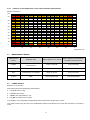
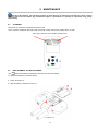
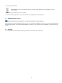
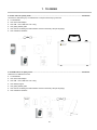
1
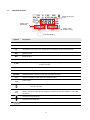
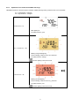
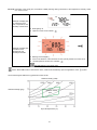
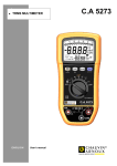
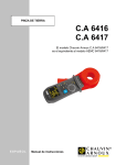
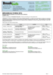
MEASUREMENT OF INDOOR AIR QUALITY CO2 AMBIENT TEMPERATURE RELATIVE HUMIDITY ENGLISH User’s manual C.A 1510 Thank you for purchasing a C.A 1510 indoor air quality meter. For best results from your instrument: read this user manual carefully, comply with the precautions for use. WARNING, risk of DANGER! The operator must refer to these instructions whenever this danger symbol appears. The product has been declared recyclable after analysis of its life cycle in accordance with the ISO14040 standard. Useful information or tip. Important instruction. The CE marking indicates conformity with European directives, in particular LVD and EMC. The rubbish bin with a line through it indicates that, in the European Union, the product must undergo selective disposal in compliance with Directive WEEE 2002/96/EC. This equipment must not be treated as household waste. Definition of measurement categories: Measurement category IV corresponds to measurements taken at the source of low-voltage installations. Example: power feeders, counters and protection devices. Measurement category III corresponds to measurements on building installations. Example: distribution panel, circuit-breakers, machines or fixed industrial devices. Measurement category II corresponds to measurements taken on circuits directly connected to low-voltage installations. Example: power supply to domestic electrical appliances and portable tools. PRECAUTIONS FOR USE This instrument complies with safety standard IEC 61010-1 for voltages of 50V in category II. The operator and/or the responsible authority must carefully read and clearly understand the various precautions to be taken in use. Do not use the instrument if it seems to be damaged, incomplete, or poorly closed. Never make measurements in atmospheres contaminated by solvents, which could damage the sensor. Before each use, check the condition of the housing. Any item of which the insulation is deteriorated (even partially) must be set aside for repair or scrapping. All troubleshooting and metrological checks must be performed by competent and accredited personnel. 2 CONTENTS 1. PRESENTATION ..................................................................................................................................................................... 4 1.1 1.2 1.3 1.4 2. USE ......................................................................................................................................................................................... 7 2.1 2.2 2.3 2.4 2.5 2.6 2.7 2.8 2.9 2.10 2.11 2.12 2.13 2.14 2.15 3. Minimum configuration .................................................................................................................................................................. 15 Communication .............................................................................................................................................................................. 15 Functions of the software .............................................................................................................................................................. 15 Installation ...................................................................................................................................................................................... 15 SPECIFICATIONS ................................................................................................................................................................. 16 4.1 4.2 4.3 4.4 4.5 4.6 4.7 4.8 4.9 5. Installing the batteries ...................................................................................................................................................................... 7 Switching the device on................................................................................................................................................................... 7 Switching the device off ................................................................................................................................................................... 7 Making a measurement................................................................................................................................................................... 7 Portable mode.................................................................................................................................................................................. 8 1D and 3D surveillance modes ....................................................................................................................................................... 8 Eco mode (Energy saving)............................................................................................................................................................ 11 P_REC mode (Programmed recording) ....................................................................................................................................... 11 MIN MAX function .......................................................................................................................................................................... 12 HOLD function (Holding the measurement) ................................................................................................................................. 13 M_REC function (Manual recording) ............................................................................................................................................ 13 Back-lighting function..................................................................................................................................................................... 13 Activation of the audible warning (Buzzer) ................................................................................................................................... 14 Change of unit of temperature ...................................................................................................................................................... 14 Display of errors and anomalies of operation............................................................................................................................... 14 AQR SOFTWARE ................................................................................................................................................................. 15 3.1 3.2 3.3 3.4 4. Introduction....................................................................................................................................................................................... 4 Side view .......................................................................................................................................................................................... 4 Side and back views ........................................................................................................................................................................ 5 The display unit ................................................................................................................................................................................ 6 Reference conditions ..................................................................................................................................................................... 16 Measurement characteristics ........................................................................................................................................................ 16 Measurement modes..................................................................................................................................................................... 17 Power supply ................................................................................................................................................................................. 17 Recording ....................................................................................................................................................................................... 18 Environmental conditions .............................................................................................................................................................. 18 Mechanical characteristics ............................................................................................................................................................ 18 Compliance with international standards...................................................................................................................................... 18 Electromagnetic compatibility........................................................................................................................................................ 18 MAINTENANCE .................................................................................................................................................................... 19 5.1 5.2 5.3 5.4 Cleaning ......................................................................................................................................................................................... 19 Replacement of the batteries ........................................................................................................................................................ 19 Metrological check ......................................................................................................................................................................... 20 Repair ............................................................................................................................................................................................. 20 6. WARRANTY .......................................................................................................................................................................... 21 7. TO ORDER ............................................................................................................................................................................ 22 7.1 Accessories and replacement parts ............................................................................................................................................. 23 3 1. PRESENTATION 1.1 INTRODUCTION Carbon dioxide is a colourless and odourless gas. It is not toxic, but at high concentrations can interfere with mental concentration and cause headaches. Outdoor air contains approximately 0.04% (400 ppm) CO 2 . In an indoor environment, human activity (breathing) can rapidly increase this concentration to values in excess of 1000 ppm (for example in meeting rooms or school classrooms). It is for this reason that the level of CO 2 is an excellent indicator of the efficacy of the renewal of indoor air. The ambient temperature and relative humidity are two more important quantities in the monitoring of indoor air quality. Beyond certain values, they can cause discomfort and favour the propagation of moulds that release allergenic or irritant substances into the air. The C.A 1510 is an instrument for measuring physical quantities that combines the following functions: Measurement of the concentration of carbon dioxide in the air (CO 2 ); Measurement of the ambient temperature; Measurement of the relative humidity; It works out air quality criteria based either on the level of CO 2 or on a combination of the three physical quantities measured. The device is a response to decree no. 2012-14 of 5 January 2012 concerning the evaluation of means of ventilation and the measurement of pollutants in the context of measurements of CO 2 . 1.2 SIDE VIEW Temperature and humidity sensors CO 2 sensor LCD display unit Short press: Back-lighting Long press: Energy-saving function Long press: Manual recording Short press: 1D and 3D modes Long press: Change of unit of temperature Buzzer On/Off Short press: Display hold Short press: Enter the MIN MAX function and view the various extreme values Long press: exit from the MIN function MAX Long press: Bluetooth On the keys, the function written above the line is invoked by a short press, the function written below the line by a long press. 4 1.3 SIDE AND BACK VIEWS Notch for hanging up the device Non-skid pads Magnet for attachment to a metallic surface Battery compartment cover Micro - USB connector 5 1.4 THE DISPLAY UNIT Display of the level of CO2 Display of the temperature Display of the relative humidity Indicates blinking Symbols Designation MEM_FULL Memory full 1D Surveillance of the level of CO 2 3D Surveillance of crossing of CO 2 , temperature, and humidity comfort zone thresholds MAX Maximum value MIN Minimum value ECO Energy-saving operating mode P_REC Programmed recording M_REC Manual recording HOLD Hold of the display MIN MAX ppm Blinking: waiting to start recording Steady: recording MIN MAX function: detection of minimum and maximum values Unit of concentration of CO 2 in the air in parts per million Buzzer active Bluetooth Blinking: waiting for connection Steady: connected Blinking: Batteries low Steady: Indicator of external power supply by connection of the mains adapter or of the USB connection. Overshoot of high threshold Overshoot of low threshold Indication of air quality and of the temperature/humidity zone of comfort 6 2. USE 2.1 INSTALLING THE BATTERIES See §5.2. 2.2 SWITCHING THE DEVICE ON 2.3 SWITCHING THE DEVICE OFF 2.3.1 Manual switching off Manual switching off is blocked if a programmed recording session (P_REC) is in progress. 2.3.2 Automatic switching off In the portable mode, the device switches itself off automatically after 15 minutes of inactivity. Automatic switching off is de-activated in the other modes (1D or 3D, ECO, P_REC), and in the MIN MAX and M_REC functions, if the Bluetooth or USB link is active or if the device is connected via the USB mains adapter. 2.4 MAKING A MEASUREMENT When the device is switched on, CO2 is displayed during the wait for the first measured of CO 2 value; access to the keys is disabled until this first value is displayed on screen. The measurements are then displayed automatically on screen. If the device is exposed to large variations of temperature, after the temperature stabilizes, wait 20 minutes before starting the measurements. The device has 4 operating modes: The portable mode, The 1D and 3D modes The ECO mode The P_REC mode It also has several functions that can be used in the various modes: The MIN MAX function The HOLD function The M_REC function The backlighting function 7 2.5 PORTABLE MODE The portable mode is the mode the device starts up in. It is in this mode that the device makes the most measurements: one every 15 seconds. It is therefore highly responsive to changes in air quality. This mode is used to inspect several rooms one after another. Install the device in a room and wait for the CO 2 measurement to stabilize (approximately 10 minutes). 2.6 1D AND 3D SURVEILLANCE MODES 1D mode: surveillance of the level of CO 2 . 3D mode: surveillance of 3 parameters: level of CO 2 and hygrothermal comfort zone. The audible and/or visual warnings alert you to overshoots. The level of CO 2 is measured every minute. 2.6.1 Activation of the 1D and 3D modes Activation of the 1D mode Activation of the 3D mode Deactivation of the 3D mode 8 2.6.2 Operation of the visible and audible warnings 1D mode: Activation of the visual (and, if activated, audible) warnings during overshoots of the CO 2 thresholds. S1 = Low threshold = 1000 ppm S2 = High threshold = 1700 ppm Level of CO 2 < S1 Back-lighting off Blinking orange back-lighting Air quality indicator: good S1 < Level of CO 2 < S2 Arrow indicating overshoot of the CO 2 threshold Air quality indicator: average The back-lighting is off in ECO mode Level of CO 2 > S2 Blinking red back-lighting Arrow indicating overshoot of the CO 2 threshold Air quality indicator: poor The back-lighting is off in ECO mode 9 3D mode: Activation of the visual (and, if activated, audible) warnings during overshoots of the temperature, humidity, and/or CO 2 comfort zones. Example of display with no overshoot of the CO 2 , temperature, and humidity comfort zones Back-lighting off Blinking red back-lighting Optimum comfort zone indicator: Example of display with overshoot of the temperature and humidity thresholds Arrow in the direction of the overshoot for each quantity outside the comfort zone. "Outside optimum comfort zone" indicator: The back-lighting is off in ECO mode For the 1D and 3D modes, if the buzzer is active, it will sound intermittently upon the appearance of the The Porcher diagram defines the hygrothermal comfort zones: Relative humidity (%RH) Absolute humidity (g/kg) Optimum comfort zone Dry-bulb temperature (°C) 10 symbol. 2.7 ECO MODE (ENERGY SAVING) The ECO mode is used when the device is left to measure the air quality in a room over a longer period. The backlighting and the buzzer are deactivated, and CO 2 is measured only once every 10 minutes. This saves the batteries. In addition, the device sets itself to sleep mode at night, from 4:30 p.m. to 8:30 a.m. These times can be programmed using the AQR software provided with the device (see § 3). To stop the function In the ECO mode, the measurement is more sensitive to instantaneous variations of CO 2 . For example, if the user breathes near the device, it may throw off the measurement. It will be necessary to wait for the next measurement to recover the true concentration of CO 2 in the room. 2.8 P_REC MODE (PROGRAMMED RECORDING) When the device is connected to a PC, you can program a recording session (see §3). There are two types of programmed recording sessions: Locked recording, in which the device displays nothing except the P_REC symbol (blinking before recording starts, then steady while recording) and the keys are inactive. At the end of recording, the device switches itself off. Unlocked recording, in which the device displays the measurements. The P_REC symbol is displayed, blinking before recording starts, then steady while recording. The device operates normally. It is not possible to change the mode, but the MIN MAX, HOLD and backlighting functions can be used. Pressing the button has no effect. 11 2.9 MIN MAX FUNCTION This function displays the maximum and minimum measured values in addition to the current value: the device compares each new measurement to those displayed. If the new measurement is greater than the former MAX value or less than the former MIN value, it replaces them in the display. The MIN MAX function cannot be used in the 1D and 3D modes. Display of MIN MAX CO2 Entering the MIN MAX function Display of MIN MAX in humidity Display of MIN MAX in temperature When the MIN MAX function is activated, recording of the minimum and of the maximum starts but the display of the three quantities measured makes it possible to continue using the device normally. To stop the MIN MAX function. 12 2.10 HOLD FUNCTION (HOLDING THE MEASUREMENT) Pressing HOLD freezes the digital display on the last measurement displayed. Activating the function does not entail interruption of recording or of the current mode, but access to the other functions of the device is disabled. To stop the function 2.11 M_REC FUNCTION (MANUAL RECORDING) You can start recording manually and all data measured are recorded in the device at the rate determined by the mode in progress (see the table in § 4.3). It is possible to record manually whatever mode is in progress (except P_REC). But once recording is in progress, it is no longer possible to change modes. To stop recording 2.12 BACK-LIGHTING FUNCTION To activate and de-activate back-lighting. The back-lighting switches itself off automatically after 10 seconds. It is impossible to activate the back-lighting in the ECO mode. 13 2.13 ACTIVATION OF THE AUDIBLE WARNING (BUZZER) Deactivation Activation First press the ECO key, then, while keeping it pressed, press the MODE key. Repeat the operation. There is no buzzer if the ECO mode is active. 2.14 CHANGE OF UNIT OF TEMPERATURE The choice of unit of temperature is preserved when the device is switched off. 2.15 DISPLAY OF ERRORS AND ANOMALIES OF OPERATION 2.15.1 OL symbol The OL symbol appears on screen when the measurement leaves the range covered by the device. In other words when: CO 2 > 5,000 ppm -10 °C < T < 60°C 5%< RH < 95% 2.15.2 Err symbol If an error of the Err type is displayed, switch the device off and back on. If the error persists, the device must be sent in for repair (see § 5.4). 2.15.3 MEM_FULL Symbol When the memory is full, the MEM_FULL symbol appears on screen. Any recording in progress is then stopped, and it is impossible to restart recording before emptying the memory. 14 3. AQR SOFTWARE AQR (Air Quality Report) software for the use of the C.A 1510 is provided with the device. 3.1 MINIMUM CONFIGURATION ® ® ® To install the AQR software, you must have a PC running Windows XP, Windows 7 or Windows 8. 3.2 COMMUNICATION The device has 2 communication modes: A Bluetooth wireless link A USB link via the cable provided When the device is connected to the PC, it is seen as a USB key and it is then possible to make copies of files. 3.2.1 Pairing the device To pair the device and the PC, you must start by activating Bluetooth on your PC. If your PC does not have a Bluetooth link, you can add a board to it or connect a Bluetooth adapter to a USB port (see § 7.1). Then power up the device and activate the Bluetooth link by a long press on the key. In the Windows bar, look for the Bluetooth logo, right-click on it, and choose Add a peripheral. If the Bluetooth logo is not present, go to Peripherals and printers in the Windows menu. Then choose Add a peripheral. The PC searches its environment for Bluetooth-compatible devices. When the C.A 1510 is detected, select it and click on Next. Choose Associate without using a code, click Next to accept the connection, then Close. If a coupling code is requested, enter 1111. 3.3 FUNCTIONS OF THE SOFTWARE The AQR software can be used to: 3.4 Configure the time ranges of the ECO mode. Configure programmed recording sessions (P_REC mode). Recover recorded data. Display records in the form of curves or tables. Calculate the air stuffiness index. Generate a summary report in pdf format. Export recorded data in spreadsheet, text, or image format. View the measurements made by the device in real time. INSTALLATION Insert the mini-CD provided with the device in your PC. Go to the AQR directory and run setup.exe. Then follow the installation instructions. To use the AQR software, refer to Help. 15 4. SPECIFICATIONS 4.1 4.2 4.2.1 REFERENCE CONDITIONS Influence quantities Reference conditions Supply voltage 3 ± 0.5V Air pollution no pollution (CO, solvents, etc.) MEASUREMENT CHARACTERISTICS CO2 measurements Type of sensor Dual-beam infrared cell Measuring principle Non-dispersive infrared (NDIR) technology Measurement range 0 to 5.000ppm Intrinsic uncertainty ±3% ±50 ppm at 25°C and 1013 mbar; in ECO mode, ±3% ±80 ppm at 25°C and 1013 mbar Response time at 63% 195 seconds Resolution (R) 1ppm 4.2.2 Influences on the measurements of CO2. The influence of the temperature is 1 ppm/°C from -10 to +45°C. The influence of the atmospheric pressure is: CO 2 real = CO 2 measured x(1 + (1013-P)x0,0014) avec P= pressure in mbar. 4.2.3 Temperature measurements Type of sensor CMOS Measurement range -10 to +60°C Intrinsic uncertainty Influence of relative humidity ±0.5°C at 50% RH ±0.5°C ±R from 10 to 40% RH Outside of the range stated above, ±0,032 x (T-25°C) ± R 0.1°C or 0.1°F Resolution (R) 4.2.4 Humidity measurement Type of sensor Capacitive Measurement range 5 to 95 %RH Intrinsic uncertainty ± 2 %RH ± R from 10 to 90 % RH ± 3 %RH ± R outside of the range stated above. Resolution (R) Measurement hysteresis 0.1 %RH ± 1 %RH Note: Prolonged exposure to values outside the 10% to 80% range may lead to a measurement bias of as much as ± 3 %RH. This bias disappears after 5 days at between 20 and 30°C and 40 and 75% RH. Rate of increase of intrinsic uncertainty < 0.5 %RH/year. 16 4.2.5 Influence of the temperature on the relative humidity measurement Relative humidity (%) 100 90 80 70 60 50 40 30 20 10 ±5 ±5 ±5 ±4 ±4 ±4 ±4 ±4 ±4 ±4 ±4 ±4 ±4 ±4 ±4 ±4 ±5 ±8 ±8 ±5 ±5 ±4 ±4 ±4 ±4 ±4 ±3 ±2 ±2 ±2 ±2 ±3 ±3 ±4 ±4 ±4 ±5 ±8 ±5 ±4 ±4 ±4 ±4 ±4 ±3 ±3 ±2 ±2 ±2 ±2 ±3 ±3 ±3 ±4 ±4 ±5 ±8 ±4 ±3 ±3 ±3 ±3 ±3 ±3 ±2 ±2 ±2 ±2 ±2 ±2 ±2 ±2 ±3 ±3 ±4 ±6 ±4 ±2 ±2 ±2 ±2 ±2 ±2 ±2 ±2 ±2 ±2 ±2 ±2 ±2 ±2 ±2 ±2 ±3 ±5 ±3 ±2 ±2 ±2 ±2 ±2 ±2 ±2 ±2 ±2 ±2 ±2 ±2 ±2 ±2 ±2 ±2 ±2 ±3 ±4 ±2 ±2 ±2 ±2 ±2 ±2 ±2 ±2 ±2 ±2 ±2 ±2 ±2 ±2 ±2 ±2 ±3 ±5 ±4 ±3 ±3 ±3 ±3 ±3 ±2 ±2 ±2 ±2 ±2 ±2 ±2 ±2 ±2 ±3 ±3 ±4 ±5 ±4 ±3 ±3 ±3 ±3 ±3 ±3 ±2 ±2 ±2 ±2 ±2 ±2 ±2 ±2 ±3 ±3 ±4 ±5 ±4 ±3 ±3 ±3 ±3 ±3 ±3 ±2 ±2 ±2 ±2 ±2 ±2 ±2 ±2 ±3 ±3 ±4 ±5 ±4 ±3 ±3 ±3 ±3 ±3 ±3 ±2 ±2 ±2 ±2 ±2 ±2 ±2 ±2 ±3 ±3 ±4 ±5 ±4 ±4 ±4 ±3 ±3 ±3 ±3 ±2 ±2 ±2 ±2 ±2 ±2 ±2 ±2 ±3 ±3 ±4 ±5 ±4 ±4 ±4 ±3 ±3 ±3 ±3 ±2 ±2 ±2 ±2 ±2 ±2 ±2 ±2 ±3 ±4 ±4 ±5 ±5 ±4 ±4 ±4 ±3 ±3 ±3 ±3 ±3 ±3 ±3 ±3 ±3 ±3 ±3 ±3 ±4 ±4 ±5 0 0 4.3 10 20 30 40 50 60 70 Temperature (°C) MEASUREMENT MODES Measurement modes Displayed value Rate of display of CO 2 values Rate of polling of the temperature and relative humidity sensors Portable Mean of 11 successive measurements Every 15 seconds Every 2 seconds 1D and 3D Mean Every minute Every 2 seconds ECO Instantaneous, not averaged Every 10 minutes Every 5 seconds P_REC Mean User-programmable User-programmable 4.4 POWER SUPPLY Batteries: 2x1.5V AA/LR6 Mean battery life (without backlighting and Bluetooth): In portable mode: 15 days In 1D 3D mode: 45 days In ECO mode: approximately 1 year In P_REC 10 minutes mode: 45 days It is possible to use rechargeable storage batteries but the life between charges will be shorter. Connected to mains using the mains--micro USB adapter provided. The batteries are not used while the device is connected to mains. 17 4.5 RECORDING Memory: 1,000,000 measurements (8 MB) FAT12 Format 4.6 ENVIRONMENTAL CONDITIONS Use indoors Operating range -10 to +60°C and 5 to 95%RH Range in storage (without battery) -20 à +60°C Altitude <2.000m 4.7 MECHANICAL CHARACTERISTICS Dimensions (L x W x H) Weight 125 x 65.5 x 32 mm approximately 190 g Protection class IP 40 per IEC60529. IK 04 per IEC50102 Free fall test Per IEC61010-1 4.8 COMPLIANCE WITH INTERNATIONAL STANDARDS Compliant with IEC61010-1 safety standard for voltages of 50V in category II. 4.9 ELECTROMAGNETIC COMPATIBILITY Emissions and immunity in an industrial setting compliant with IEC 61326-1. 18 5. MAINTENANCE Except for the batteries, the instrument contains no parts that can be replaced by personnel who have not been specially trained and accredited. Any unauthorized repair or replacement of a part by an "equivalent" may gravely impair safety. 5.1 CLEANING Disconnect the instrument completely and switch it OFF. Use a soft cloth, dampened with soapy water. Rinse with a damp cloth and dry rapidly with a dry cloth. Take care to keep the sensor intakes perfectly clean. 5.2 REPLACEMENT OF THE BATTERIES The symbol indicates that the batteries are spent and must be changed. To replace the batteries, proceed as follows: Switch the device off. Slide the battery compartment cover off. 19 Remove the old batteries. Spent batteries must not be treated as ordinary household waste. Take them to the appropriate recycling collection point. 5.3 Insert the new batteries with the correct polarity. Close the battery compartment cover: make sure that it is completely and correctly closed. METROLOGICAL CHECK Like all measuring or testing devices, the instrument must be checked regularly. This instrument should be checked at least once a year. For checking and calibration, contact one of our accredited metrology laboratories (information and contact details available on request), at our Chauvin Arnoux subsidiary or the branch in your country. 5.4 REPAIR For all repairs before or after expiry of warranty, please return the device to your distributor. 20 6. WARRANTY Except as otherwise stated, our warranty is valid for twelve months starting from the date on which the equipment was sold. Extract from our General Conditions of Sale provided on request. The warranty does not apply in the following cases: Inappropriate use of the equipment or use with incompatible equipment; Modifications made to the equipment without the explicit permission of the manufacturer’s technical staff; Work done on the device by a person not approved by the manufacturer; Adaptation to a particular application not anticipated in the definition of the equipment or not indicated in the user’s manual; Damage caused by shocks, falls, or floods. 21 7. TO ORDER C.A 1510 indoor air quality meter ........................................................................................................................... P01651010 The device is anthracite grey. It is delivered in a compact metal carrying case with: 2 LR6 batteries One mains-USB adapter One USB - micro USB cord 1.80 m long One getting started guide One mini CD containing the AQR software and user’s manuals (1 file per language) One verification certificate C.A 1510W indoor air quality meter ........................................................................................................................ P01651011 Delivered in a cardboard box with: 2 LR6 batteries One mains-USB adapter One USB - micro USB cord 1.80 m long One desktop support One getting started guide One mini CD containing the AQR software and user’s manuals (1 file per language) One verification certificate 22 7.1 ACCESSORIES AND REPLACEMENT PARTS Field calibration kit ............................................................................................................................................... P01651022 Wall mount ........................................................................................................................................................... P01651020 Carrying case ...................................................................................................................................................... P01298071 Desktop support .................................................................................................................................................. P01651021 It is attached to the wall. It can be used to protect the device against theft by adding a padlock. Mains adapter with USB cable .................................................................................................................................. P01651023 USB-Bluetooth adapter ............................................................................................................................................. P01102112 23 07 - 2014 Code 694156A02 - Ed. 2 DEUTSCHLAND - Chauvin Arnoux GmbH Straßburger Str. 34 - 77694 Kehl / Rhein Tel: (07851) 99 26-0 - Fax: (07851) 99 26-60 SCHWEIZ - Chauvin Arnoux AG Moosacherstrasse 15 - 8804 AU / ZH Tel: +41 44 727 75 55 - Fax: +41 44.727 75 56 UNITED KINGDOM - Chauvin Arnoux Ltd Unit 1 Nelson Court – Flagship Sq-Shaw Cross Business Pk Dewsbury, West Yorkshire – WF12 7TH Tel : 019244 460 494 – Fax : 01924 455 328 CHINA - Shanghai Pu-Jiang - Enerdis Instruments Co. Ltd 3 Floor, Building 1 - N° 381 Xiang De Road Hongkou District - 200081 SHANGHAI Tel: +86 21 65 21 51 96 - Fax: +86 21 65 21 61 07 ITALIA - Amra SpA Via Sant’Ambrogio, 23/25 - 20846 Macherio (MB) Tel: 039 245 75 45 - Fax: 039 481 561 ESPAÑA - Chauvin Arnoux Ibérica SA C/ Roger de Flor N° 293, Planta 1- 08025 Barcelona Tel: 902 20 22 26 - Fax: 934 59 14 43 ÖSTERREICH - Chauvin Arnoux Ges.m.b.H Slamastrasse 29/2/4 - 1230 Wien Tel: 01 61 61 961-0 - Fax: 01 61 61 961-61 MIDDLE EAST - Chauvin Arnoux Middle East P.O. BOX 60-154 - 1241 2020 JAL EL DIB (Beirut) – LEBANON Tel: (01) 89 04 25 - Fax: (01) 89 04 24 SCANDINAVIA - CA Mätsystem AB Sjöflygvägen 35 - SE 18304 TÄBY Tel: +46 8 50 52 68 00 - Fax: +46 8 50 52 68 10 USA - Chauvin Arnoux Inc - d.b.a AEMC Instruments 200 Foxborough Blvd. - Foxborough - MA 02035 Tel: (508) 698-2115 - Fax: (508) 698-2118 http://www.chauvin-arnoux.com 190, rue Championnet - 75876 PARIS Cedex 18 - FRANCE Tel.: +33 1 44 85 44 85 - Fax: +33 1 46 27 73 89 - [email protected] Export: Tél.: +33 1 44 85 44 86 - Fax: +33 1 46 27 95 59 - [email protected] 24