1
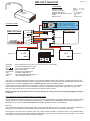
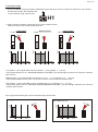
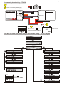
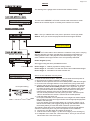
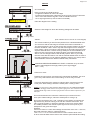
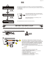
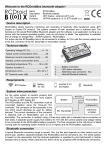
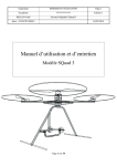
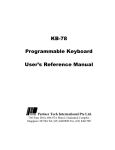
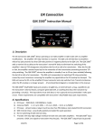
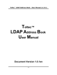
HELI ALT Hold Unit
User Manual
HELI ALT Hold Unit
Page 1 of 7
Tube
Technical data:
Operation voltage:
Current consumption:
Operation temperature:
Operation altitude above sea level:
Weight
Measurements
Barometric
sensor
H1 mode
In case of CCPM mixing you
must mix the servo movements
on board of the heli and plug
the pitch lead in to the mixing device
like the Helicommand or similar.
Connection schema
HELI ALT Hold
ver. 1.1x
Intelligent control unit
Pitch RX
Button
Gen.
Pitch
Unit On/Off
Led
JeTi Box
Batt. 5..15V
Pitch
RC Receiver
Unit On/Off
LED
-
+
-
+
JETI BOX
Safety Accu
5..15V
Batt. 2
Pitch RX
Button
Gen.
Pitch
Unit On/Off
LED
JeTi Box
Batt..
Batt. 1 = 4.8 - 6 V
Batt. 2 = 5 - 15 V
50 mA
-10...70 Celsius
0 - 2500m
30g
50x30x13 mm
4.8V
Receiver Accu
Batt. 1
servo signal from the receiver, TX must be set to H1 Heli Mode
external calibration button input
servo signal generator output
pitch servo output
receiver servo signal input
indication LED output
HELI ALT Hold unit setting input
external battery socket
The HELI ALT Hold was designed to help the pilot maintain desired altitude when filming or taking pictures from RC
helicopter. It can maintain present altitude, or programmed altitude. As its side function it can generate constant servo
signal to free a channel on the transmitter. Example: gyro or governor sensitivity setting.
It works only if there is another devise mixing the CCPM servos signals on the board of your machine. (For example
Helicommand or similar devices. The transmitter is set to H1 mode where each function operates only one servo.
HELI ALT Hold outputs only one servo signal for the collective pitch function.
HELI ALT Hold may be powered from the receiver battery as well as from an external pack plugged directly in
to the unit.
If you decide not to use the external battery be aware of this:
The RC battery must supply voltage from 4.8 up to 6.5V. If it drops below 4.8V the internal barometric pressure sensor
voltage reference will start working with a certain offset. In reality the HOLD PRESENT LEVEL function will be not
affected by this, only the PREPROGRAMMED ALTITUDE will differ from the real maintained.
Example:
The voltage has dropped below the stated level. The programed altitude is set to 15 meters. The heli will maintain the
height at 10 meters due to the low internal voltage reference. All other functions would stay unaffected.
We suggest to use both types of powering the unit. It will increase the safety of using the device. The external battery
would power only the HELI ALT Hold circuits without effecting the rest of the electronics on the helicopter. The unit will
always drew current from the battery with higher voltage.
Page 2 of 7
Transmitter setting
1. As you are already using some kind of stabilisation device the heli is set to H1 mode (one channel for one collective
function) No mixing in the transmitter but
on your machine using other devices.
H1
2. Select a three momentary switch used for ALT Hold enable channel.
Select the values for the three positions like this:
Low position
Middle position
High position
1.3
1.5 1.7
ms
Volt
TX-bar
Volt
TX-bar
Volt
TX-bar
1.3
1.5 1.7
ms
1.3
1.5 1.7
ms
Low position - servo signal width must be set below 1.3 ms (typically 1... 1.29 ms).
This position switches on the “MAINTAIN PRESENT ALTITUDE”. The LED will light. Pilot does not control the collective
pitch function
Middle position - servo signal width must be set to 1.3 ms .... 1.7 ms (typically 1.31 ... 1.69 ms).
This position disables the ALT Hold. The LED is not active. Pilot controls the collective pitch.
High position - servo signal width must be set higher than 1.7 ms (typically 1.71 ... 2.1 ms).
This position switches on the “MAINTAIN PREPROGRAMMED ALTITUDE”. The LED will light. Pilot does not control the
collective pitch function.
Servo signal width leaving the receiver should be kept in these limits:
Min. signal from TX
Volt
Volt
Max. signal from TX
0.9
1.5
2.1 ms
0.9
1.5
2.1 ms
Page 3 of 7
Programming the althold by JETIBOX
1
Step 1 - connect the JeTi Box
2
Step 2 - connect power supply
HELI ALT Hold
ver. 1.1x
Intelligent control unit
Pitch RX
Button
Gen.
Pitch
Unit On/Off
Led
JeTi Box
Batt. 5..15V
Pitch
RC Receiver
Unit On/Off
LED
2
1
JETI BOX
-
+
First connect the JeTiBox
4.8V
Receiver Accu
Batt. 1
JeTi Box will show initial menu and you can start the setting - see JeTi diagram
Alt Hold-HELI
ver.1.xx
Last held alt.
0000 m
Select settings
HELI
Select heli weight
Hover weight 1
SET
1.5 ms
Hover weight 2
SET
AltHLD
Heli weight
1
Altitude
1.4 ms
Hover weight 3
SET
121 m
Pitch servo min.
1.3 ms
-0.21ms
Pitch servo max.
+0.18ms
Disconect JeTiB
Then calibrate
Servo delay
005
JETI BOX
Output Generator
Disconnect JeTiBox
1.18ms
Data stored
Page 4 of 7
MENUS
Alt Hold-HELI menu
Alt Hold-HELI
ver.1.xx
This would give the gadget name as well as the software version.
Last held altitude - menu
Last held alt.
0000 m
The last HOLD PRESENT ALTITUDE command will memorize its actual
altitude to the internal eeprom. It will stay there until the new record.
Select settings - menu
HELI - Here you calibrate the hover point in presence of three pay loads.
Select settings
HELI
AltHLD
AltHLD - Here you choose the payload and enter the height if desired
Please go to page 5
Hover weight - menu
Number of the payload set
Hover weight 1
SET
1.5 ms
Purpose:
The HELI ALT Hold needs to know where the collective hover point is carrying
different payloads. We have included three heli payload combinations to
satisfy general needs. If the payload is switched during the job, you just
enter a different heli weight number of the set up already calibrated.
Hower weights (1 to 3).
We suggest using the three possibilities like this:
Last stored value
Hover weight 1 - Without payload for testing reasons
Hover weight 2 - Intended to use with the camera and cradle added weight
Hover weight 3 - Intended for the video camera use.
Disconnect JeTi B
Then calibrate
Hover point setting
NO
How to do the calibration of hover points
1. Select hover weight number - 1 to 3
2. Push the left arrow for SET - after you can see what the arrow points at.
3. Disconnect the JeTi Box (calibrate - meaning in flight)
4. Switch the three position switch to the middle position. LED does not light.
5. Hover the heli at a height where it is not influenced by the ground effect.
6. If happy with the way it hovers, flip the switch from middle to any position.
Return the switch to the middle position. This is important. If you do
not return the switch, the ALT Hold will monitor the collective pitch signal
until you land and switch off the battery. This will result in to saving the
collective pitch position at the time of switching off the battery.
You can do this procedure how many times you want. The hover point
value is stored when the switch is returned to the middle position.
7. Land and switch the power off.
Hover point calibration for this particular hover weight has ended. Repeat
this procedure for each heli weight number with the appropriate payloads
added to the helicopter.
If you are already using the spare battery do not forget to switch it of as
well as the RC battery. We suggest going through the calibration without
the auxiliary battery to make the switch off and on process easier.
The following steps are just for checking that the unit really saved different
values for each hover point. They are not important for the calibration.
8. Connect the JeTi Box again and switch the power on
9. Find the menu Hover weight 1 (or the hover weight you are working on)
10. In adequate menu check the “Last stored value”. There you can see the
stored value of the new hover point.
Page 5 of 7
MENUS
ALT Hold menu:
Select settings
HELI
AltHLD
Here you set the ALT Hold functions:
- Programmed altitude for each heli weight
- Positive and negative Pitch offset from the hover point. The ALT Hold uses
this to move the collective signal in order to maintain the level.
- servo signal generator (to free a channel if needed)
Please go to page 4
follow the diagram for the setting
Heli weight - menu
Select heli weight
Heli weight
1
Select the heli weight for which the following settings will be made
Change value
Altitude - menu
Altitude:
(Note: Altitude value is valid for all 3 heli weights)
Altitude
121 m
Change value
High position
TX-bar
This comes handful if you want to take pictures from a desired altitude level.
You set it here and the heli will go there after the function is switched on.
The actual precision is given by the sensor tube entrance position as well as
the take off altitude. Here I want to say that if the height is set for example
to 20 meters, it does not mean the heli would go to 20 meters above the take
off point and hold there. It means It will go always to the same altitude but it
does not have to be exactly 20 meters because of the thinks mentioned
above. The low voltage influence was already spoken about. If you really
intend to work with this feature a lot and the entered altitude does not refer to
the really maintained, you can make a calibration chart for your set up where
entered altitude would mean different altitude really maintained.
“MAINTAIN PREPROGRAMMED ALTITUDE” is switched on by the three
position switch flipped to the high position (servo signal bigger
than 1.7 ms)
Pitch servo menu:
Pitch servo - menu
Determines how brutal or smooth the ALT Hold keeps the altitude. You must
give it a try. Start with the 50% of the setting. If it is too lazy, increase.
Pitch servo min.
-0.21ms
Change value
Pitch servo max.
+0.27ms
Change value
This menu determines the maximum collective down movement from the
hover point. While setting it watch the swash plate. It must go down.
Realize: The more the ALT Hold activation altitude differs from the PREPROGRAMMED
ALTITUDE, the bigger offset from the hover point is going to be used. It is the ALT Hold
maintain altitude logic. Think of it when flying and test it to know what to expect from your
helicopter.
This menu determines the maximum collective up movement from the
hover point. While setting it, watch the swash plate. It must go up.
Do not get confused by the + and - indication on the display. It indicates the
signal level only and has nothing to do with the collective movement. This
value could be negative or positive it depends on the servo reverse status.
The middle position of the collective pitch signal is the hover point of your
helicopter for the given heli weight.
Example:
If the hover value is 1.50ms after settings and the Pitch servo min.= +0.27 ms,
than total maximum value for collective down is:
1.50 + 0.27 = 1.77 ms. This will be used as a max collective down move.
In other words Alt Hold would not drive the collective pitch behind this setting.
Page 6 of 7
MENUS
The speed of the collective pitch reaction to go back to the desired altitude if
the height was changed due to the outside forces (wind or turbulence and so on)
1 - fast reaction
9 - slow reaction
Servo delay
005
Change value
Servo signal generator output - very useful to free
a channel on the receiver. Typical use for a governor
setting or gyro sensitivity setting.
Pitch RX
Button
Output Generator
Gen.
1.18ms
Pitch
Unit On/Off
Led
JeTi Box
Batt. 5..15V
Change value
Data stored
Servo signal generator runs constantly. It is not
possible to switch it off.
All set parameters are stored in the internal memory
BEFORE THE FIRST FLIGHT
Supposing you have done the hover point calibration procedure. (Do it without hovering at first to learn the procedure)
Check all functions on your heli and on your transmitter
H1
Calibrate the pressure sensor
Pitch RX
Button
1
Gen.
Pitch
Unit On/Off
Led
JeTi Box
Batt. 5..15V
LED
-
+
2
Batt
3
We suggest you calibrate before each flight. That way the
sensor knows the altitude at the ground level. This affects the
preprogrammed altitude - if you did not calibrate and then send
the heli to the programmed altitude, it would go to that height
with respect to the last calibration. Realize that atmospheric
pressure changes. Realize that various take off locations can
differ by their altitude. All this affects the sensor.
Note: if you want to maintain present level the calibration does
not matter.
How to do it?
1. Disconnect the HELI ALT Hold power supply
2. Keep the calibration button pressed
3. Switch on the power supply for the HELI ALT Hold unit
4. LED must start blinking
5. Release the button, LED is still blinking.
6. Calibration time is 7 - 10 seconds
7. Completed after the LED has stopped blinking
8. Memorized until the new calibration
Page 7 of 7
Preflight test of the HELI ALT Hold unit functions - on the ground
Middle position
TX-bar
2.1 ms
LED = OFF
Collective pitch controlled from TX,
it moves according to the pitch stick position.
1.5 ms
0.9 ms
Low position
TX-bar
2.1 ms
LED = ON
Collective pitch controlled by the ALT Hold.
PILOT NOT IN COMMAND of the collective pitch.
ALT Hold moves the swash plate to the hover
point, as it maintains present level.
In the meantime the present altitude is saved in
the menu LAST HELD ALTITUDE. Is it there?
It should display 0000 or 0001 as the heli did
not climb anywhere still being on the ground.
LED = ON
Collective pitch controlled by the ALT Hold.
PILOT NOT IN COMMAND of the collective pitch.
ALT Hold moves the swash plate some distance
above the hover point as it wants to climb to the
programmed altitude. The more the
programmed altitude differs from the ground
altitude, the more the collective pitch moves.
1.5 ms
0.9 ms
High position
TX-bar
2.1 ms
1.5 ms
0.9 ms
Important notes:
(Of course you must have entered the
programmed altitude beforehand)
When the ALT Hold is on, you are not in control of the collective pitch.
Be always prepared to switch the ALT Hold off.
When switching the ALT Hold modes in flight, make sure the TX collective pitch stick is close to the hover position.
If it is not, expect sudden altitude changes. Example: You send the heli to the programmed 50m altitude. While enjoying
the automatic hover, you have shifted the collective stick down without knowing. Than you switch the ALT Hold off. The
heli will jump in to a fast descent because your collective stick is in a negative pitch position.
YO-YO EFFECT: This does not refer to the Hold Present Level function, but rather Go To The Preprogrammed Altitude.
It happens when the heli is higher than the programmed level. The more the activation height differs from the
programmed altitude, the bigger the yo-yo effect is. Example: Programmed level 70m. Your heli is at 150m. There you
switch on the Go To The programmed Altitude. The heli will start descend quite fast. The height difference is big, therefore
the collective pitch down offset from the hover point is big as well. The heli crosses the programmed 70m level, stops
somewhere about 50m and climbs to 70m to hold there. Do not activate the Go To The Preprogrammed Altitude if the
heli is much higher than the programmed level. Also take in to consideration the weight of the heli and its power.
If the programmed level is set too low, the heli could hit the ground due to the yo-yo effect.
Avoid moisture, do not blow in to the sensor tube touching it with the lips but only blow air distanced in to the tube to
check the sensor is working.
Place the sensor tube entrance to a convenient place (where there are no sudden pressure changes). It could be right
below the rotor blade holders, inside the canopy, below the canopy, above the rear rotor. It needs to be tried for each heli.
The tube entrance should be enclosed by some kind of foam that lets air go through easily.
Questions regarding the Heli Alt Hold can be sent via email. [email protected]
See the Alt Hold video use at
www.leteckafotografie.com - section Heli Alt Hold
Product manufactured by
www.modelcam.cz
Heli Alt Hold is warranted to be free from defects in materials and workmanship for a period of one year from the date of purchase. This limited warranty covers normal
use and does not cover abuse or use not in accordance with this manual.
Under no circumstance will the seller be responsible for any incidental or consequential damages, which may occur during the use of this product, or as a result of the
product's failure to perform.