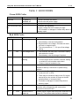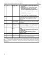
1
Kelly KSL Sensorless Motor Controller User’s Manual V 1.2 Kelly KSL Brushless Motor Controller User’s Manual Devices Supported: KSL24100 KSL24200 KSL36100 KSL36200 KSL48100 KSL48200 KSL48400B KSL72100 KSL72200 KSL72400B KSL96150 KSL24150 KSL24300 KSL36150 KSL36300 KSL48150 KSL48300 KSL48500B KSL72150 KSL72300 KSL72500B KSL96250 Rev.1.2 Dec. 2012 Kelly KSL Sensorless Motor Controller User’s Manual V 1.2 Contents Chapter 1 Introduction ................................................................................. 2 1.1 Overview ........................................................................................... 2 Chapter 2 Features and Specifications ........................................................ 3 2.1 General functions .............................................................................. 3 2.2 Features ............................................................................................ 3 2.3 Specifications..................................................................................... 4 2.4 Name Regulation ............................................................................... 4 Chapter 3 Wiring and Installation ................................................................ 5 3.1 Mounting the Controller ..................................................................... 5 3.2 Connections....................................................................................... 6 3.3 Installation Check List ...................................................................... 10 Chapter 4 Maintenance ............................................................................. 15 4.1 Cleaning .......................................................................................... 15 4.2 Configuration ................................................................................... 15 Table 1: LED CODES .................................................................................. 16 Green LED Codes ................................................................................. 16 Red LED Codes..................................................................................... 16 Contact Us: .................................................................................................. 18 1 Kelly KSL Sensorless Motor Controller User’s Manual V 1.2 Chapter 1 Introduction 1.1 Overview This manual introduces the Kelly KSL motor controllers‟ features, their installation and their maintenance. Read the manual carefully and thoroughly before using the controller. If you have any questions, please contact the support center of Kelly Controls, LLC. KSL sensorless and brushless series motor drivers and controllers are developed by Kellycontrols,LLC independently. It is suitable for fans, water pumps, air conditioner compressors, fridge compressor applications and etc. It uses high power MOSFET‟s and, PWM to achieve efficiencies of up to 99% in most cases. A powerful microprocessor brings in comprehensive and precise control to the controllers. It also allows users to adjust parameters, conduct tests, and obtain diagnostic information quickly and easily. 2 Kelly KSL Sensorless Motor Controller User’s Manual V 1.2 Chapter 2 Features and Specifications 2.1General functions (1) Extended fault detection and protection. The LED flashing pattern indicates the fault sources. (2) Monitoring battery voltage. It will stop driving if the battery voltage is too high and it will progressively cut back motor drive power as battery voltage drops until it cuts out altogether at the preset “Low Battery Voltage” setting. (3) Built-in current loop and over current protection. (4) Configurable motor temperature protection range. (5) Current cutback at low temperature and high temperature to protect battery and controller. The current begins to ramp down at 90ﹾCcase temperature, shutting down at 100ﹾC. (6) Configurable and programmable with a host computer though RS232 or USB. Provide free GUI which can run on Windows XP/2000, Windows 7 and Vista(recommend using Kelly Standard USB To RS232 Converter). (7) Provision of a +5 volt output to supply various kinds of sensors, including Hall effect type. (8) Reversing switch. Closing to ground is to activate. (9) 0-5V: Default to throttle input. (10) Optional CAN bus.(temporary unavailable) (11) Optional supply voltage 8V-30V. 2.2 Features 1) 2) 3) 4) 5) 6) 7) 8) Intelligence with powerful microprocessor. Synchronous rectification, ultra low drop and fast PWM to achieve very high efficiency. Current limit . Battery current limiting available, doesn‟t affect taking off performance. Configurable limit for motor current. Low EMC. LED fault code. Battery protection: current cutback, warning and shutdown at configurable high and low battery voltage. 9) Rugged aluminum housing for maximum heat dissipation and harsh environment. 10) Rugged high current terminals, and rugged aviation connectors for small signal. 11) Thermal protection: current cut back, warning and shutdown at high temperature. 12) Current multiplication: Take less current from battery, output more current to motor. 13) Easy installation: 3-wire potentiometer will work. 14) Motor stall protection 15) Up to 17,000 electric RPM. (Electric RPM=mechanical RPM * motor poles) 16) Standard PC/Laptop computer is used to do programming. No special tools needed. 17) User program provided. Easy to use. No cost to customers. 3 Kelly KSL Sensorless Motor Controller User’s Manual V 1.2 2.3 Specifications •Frequency of Operation: 16.6kHz. •Standby Battery Current: < 2mA. •5V Sensor Supply Current: 40mA. •Controller supply voltage range, PWR, 8V to 30V for 24V controllers. 18V to 90V for controllers rated equal or lower than 72V. 18V to 120V for 96V controllers. •Supply Current, PWR, 150mA. •Configurable battery voltage range, B+. Max operating range: 18V to 1.25*Nominal Voltage. 8V to 30V for rated equal 24V. •Standard Throttle Input: 0-5 Volts(3-wire resistive pot), 1-4 Volts(hall active throttle). •Analog Throttle Input: 0-5 Volts. Producing 0-5V signal with 3-wire pot. •Reverse Alarm, Main Contactor Coil Driver, Meter: <200mA.(temporary unavailable) •Full Power Operating Temperature Range: 0ﹾC to 50ﹾC (controller case temperature). •Operating Temperature Range: -30ﹾC to 90ﹾC,100ﹾC shutdown(controller case temperature). •Motor Current Limit, 1 minute: 100A -500A, depending on the model. •Motor Current Limit, continuous: 50A - 250A, depending on the model. •Max Battery Current : Configurable. 2.4 Naming Regulations The naming regulations of Kelly BLDC motor controllers: 4 Kelly KSL Sensorless Motor Controller User’s Manual V 1.2 Chapter 3 Wiring and Installation 3.1 Mounting the Controller The controller can be oriented in any position which should be as clean and dry as possible, if necessary, shielded with a cover to protect it from water and contaminants. To ensure full rated output power, the controller should be fastened to a clean, flat metal surface with four screws. Applying silicon grease or some other thermal conductive material to contact surface will enhance thermal performance. Proper heat sinking and airflow are vital to achieve the full power capability of the controller. The case outline and mounting holes‟ dimensions are shown in Figure 1. Tall: 62 millimeters Figure 1: mounting holes‟ dimensions (dimensions in millimeters) 5 Kelly KSL Sensorless Motor Controller User’s Manual V 1.2 3.2 Connections 3.2.1 Front Panel of BLDC Motor Controller: Five metal bars and two plugs (J1, J2) are provided for connecting to the battery, motor and control signals in the front of the controller shown as Figure 2. Figure 2: Front panel of BLDC motor controller B+: battery positive B-: battery negative A: Output U/1/A phase B: Output V/2/B phase C: Output W/3/C phase Figure 3: The connecting diagram of J1 and J2 J1 Pin Definition 6789- 1- PWR: Controller power supply (output). The pin is Red LED for S/N less :08XXXXXX. 2- Current meter. <200mA(temporary unavailable) 3- Main contactor driver. <2A(temporary unavailable) 4- Alarm: To drive reverse beeper. <200mA 5- RTN: Signal return Green LED: Running indication RTN: Signal return RS232 receiver RS232 transmitter 6 Kelly KSL Sensorless Motor Controller User’s Manual V 1.2 10- CAN bus high(temporary unavailable) 11- CAN bus low(temporary unavailable) 12- Reserved 13- RTN: Signal return, or power supply return 14- Red LED: Fault code. The pin is PWR for S/N less :08XXXXXX. J2 Pin Definition 1. PWR: Controller power supply (input) 2. RTN: Signal return, or power supply return 3. RTN: Signal return 4. Motor temperature input.(temporary unavailable) 5. Throttle analog input, 0-5V 6. Brake analog input, 0-5V(temporary unavailable) 7. 5V: 5V supply output. <40mA 8. Micro_SW: Throttle switch input(temporary unavailable) 9. Reversing switch input 10. Brake switch input(temporary unavailable) 11. Hall phase C(temporary unavailable) 12. Hall phase B(temporary unavailable) 13. Hall phase A(temporary unavailable) 14. RTN: Signal return Notes: 1. All RTN pins are internally connected. RTN is internally connected to B2. Two PWR pins, J1-1 and J2-1, are internally connected. Switch to return is active. Open switch is inactive. Caution: • Do not apply power until you are certain the controller wiring is correct and has been double checked. Wiring faults will damage the controller. • Ensure that the B- wiring is securely and properly connected before applying power. • The preferred connection of the system contactor or circuit breaker is in series with the B+ line. • All contactors or circuit breakers in the B+ line must have precharge resistors across their contacts. Lack of even one of these precharge resistors may severely damage the controller at switch-on. 7 Kelly KSL Sensorless Motor Controller User’s Manual V 1.2 3.2.2 Wiring of BLDC Motor Controller Figure 4: Standard Wiring for KSL Controllers 8 Kelly KSL Sensorless Motor Controller User’s Manual Figure 5: 9 BLDC controller preferred wiring (24V supply is preferred) V 1.2 Kelly KSL Sensorless Motor Controller User’s Manual V 1.2 3.2.3 Communication Port A RS232 port is provided to communicate with host computer for calibration and configuration. Figure 6: standard RS232 Interface 3.3 Installation Check List Before operating the motor, complete the following checkout procedures. Use LED code as a reference as listed in Table 1. Make sure the wire is connected correctly Turn the PWR switch on. The LED should blink, and the Green LED keeps on when the controller runs under sensorless mode. If this does not happen, check continuity of the PWR and return. The fault code will be detected automatically at restart. Turn the sensorless switch on or off, select a direction and operate the throttle. The motor should spin in the selected direction. Verify wiring or voltage and the fuse if it does not. The motor should run faster with increasing throttle. If not, refer to the Table 1 LED code, and correct the fault as determined by the fault code. Take the motor off the blocks and drive it in a clear area. It should have smooth acceleration and good power if sensorless parameters are set correctly. 10 Kelly KSL Sensorless Motor Controller User’s Manual V 1.2 3.4 Begin To Use Please read this instructions seriously and adjust parameters carefully before using our sensorless controller! Detailed description of sensorless page of GUI: (1).Please choose appropriate motor standard voltage according to name plate of your motor or from your motor supplier. (2).Please choose appropriate motor standard rpm according to name plate of your motor or from your motor supplier. (3).Please choose appropriate motor poles according to name plate of your motor or from your motor supplier. (4).Demand Used For Lock Position. If the Lock Position Demand parameters are set too high, the rotor will oscillate when it reaches the lock positions. If they are too low, the rotor will not move to the reference position. Try increasing or decreasing the Lock Position Demand parameters until the rotor moves quickly to the two lock positions with a minimum of oscillation. (5).Lock Position Time. Loads that have a lot of inertia, such as a large diameter fan blade, may need a longer holding time to allow the rotor oscillations to decay. The lock times for low inertia loads can generally be set to a very low value to allow the motor to start quickly. 11 Kelly KSL Sensorless Motor Controller User’s Manual V 1.2 (6).Demand Used At Start of Ramp and Demand Used At End of Ramp. The key to set these demands is to accelerate the motor to the end speed without 'slipping' or excessive mechanical vibration. The best way to set these demands is to observe the rotor while starting and listen to the sound that the motor makes when it is energized. As the starting routine executes, most motors will make a ticking noise with frequency proportional to the ramp speeds. If you hear the ramp speed increasing, but the rotor appears to be spinning slowly or just oscillating in a stationary position, then the ramp demands probably need to be increased. If the rotor appears to be accelerating properly, but there seems to be excessive motor vibration, over-current trips, or excessive noise during ramping, the ramp demands are probably set too high. In most cases, you will want to set the Ramp End Demand parameter 5% to 15% higher than the Ramp Start Demand parameter. NOTE: When setting options (4),(5) and (6), please gradually add them from the minimum value until the motor is latched, ramping and running to sensorless smoothly and successfully. Do not set a higher value at the beginning, or it will cause over-current even destroy your controller!!! Usually you only need to set three parameters: motor rated voltage, motor rated speed, motor poles according to your motor type. We have setted other parameters to appropriate value when leaving factory unless special requirement. If you meet other problems when operating our sensorless controller or setting parameters, you can email us to the address in last page. 12 Kelly KSL Sensorless Motor Controller User’s Manual V 1.2 (7).Duration of Starting Ramp. In general, you should start with a relatively long ramping time to ensure the motor is starting properly. A ramping time between 2 and 4 seconds should be appropriate for most motor and load combinations. You will find that loads with greater inertia require a longer ramp time for proper acceleration. As the ramp time is decreased, you may also have to increase the Ramp Start Demand and Ramp End Demand parameters to avoid rotor slipping during startup. (8).Sensorless Fault auto restart. Enable or disable auto restart function if switchs to sensorless state error from ramping. (9).Resart Waiting Time. Set restart waiting time after sensorless running error. This option is effective only after auto restart function is enabled. Parameters set example: Motor standard parameters:48V/1500RPM, 8 poles. [1].Choose motor standard voltage 48V [2].Choose motor standard speed 1500rpm [3].Choose motor poles 8. 13 Kelly KSL Sensorless Motor Controller User’s Manual V 1.2 [4].Adjust target voltage percent of locking period. set 1%here,noload.depend on motor load. [5].Lock time. set 2 seconds here. depend on motor load. [6].Demand Used At Start of Ramp. it is usually 1% or 2% higher than 'Demand Used For Lock Position'.set 2% here, noload.depend on motor load. Demand Used At End of Ramp. it is usually 5% or 15% higher than 'Demand Used At Start of Ramp'. set 3% here, noload. [7].Duration of Starting Ramp. set 4 seconds here. depend on load. Operation Instruction: (1).Please check whether throttle input voltage is zero before turning sensorless switch on, otherwise your motor will not start. (2).The red led lights up after sensorless switch is on 2s .It indicates motor begins to enter lock and ramp mode and throttle input is invaild now.when red led goes out and green led lights up, it indicates motor switchs into sensorless state sucessfully and you can use throttle to adjust motor speed now. (3).Please wait until the motor stops running completely then can you turn sensorless switch on to start motor once again. (4).Please turn sensorless switch off and check whether throttle input voltage is zero before using reverse switch.you can also change direction by directly adjusting any two of the three phase wire sequence connected to controller. 14 Kelly KSL Sensorless Motor Controller User’s Manual V 1.2 Chapter 4 Maintenance There are no user-serviceable parts inside the controllers. Do not attempt to open the controller as this will void your warranty. However, periodic, exterior cleaning of the controller should be carried out. The controller is a high powered device. When working with any battery powered motor, proper safety precautions should be taken that include, but are not limited to, proper training, wearing eye protection, avoidance of loose clothing, hair and jewelry. Always use insulated tools. 4.1 Cleaning Although the controller requires virtually no maintenance after properly installation, the following minor maintenance is recommended in certain applications. Remove power by disconnecting the battery, starting with battery positive. Discharge the capacitors in the controller by connecting a load (such as a contactor coil, resistor or a horn) across the controller‟s B+ and B- terminals. Remove any dirt or corrosion from the bus bar area. The controller should be wiped down with a moist rag. Make sure that the controller is dry before reconnecting the battery. Make sure the connections to the bus bars, if fitted, are tight. To avoid physically stressing the bus bars use two, well-insulated wrenches. 4.2 Configuration You can configure the controller with a host computer through either an RS232 or USB port. Disconnect motor wiring from controller. Do not connect B+, throttle and so on. The controller may display fault code in some conditions, but it doesn't affect programming or configuration. Use straight through RS232 cable or USB Converter provided by Kelly to connect to a host computer. Provide >+18V (either J2 pin1 or J1 pin14) to PWR. Wire power supply return to any RTN pin. Download the free configuration software from: http://www.kellycontroller.com/support.php Caution: •Make certain that the motor is disconnected before trying to run the Configuration Software! •Configuration software will be regularly updated and published on the website. Please Update your Configuration Software regularly. You must uninstall the older version before updating. •When setting "Hall Sensor Type" in GUI, do not use "Auto-Check". This has been deleted from the newer configuration software versions. 15 Kelly KSL Sensorless Motor Controller User’s Manual V 1.2 Table 1: LED CODES Green LED Codes LED Code Green Off Green On Green & Red are both On Explanation No power or switched off Normal operation Solution 1. Check if all wires are correct. 2. Check fuse and power supply. That‟s great! You got solution! 1. Software still upgrading. 2. Supply voltage too low or battery too high 3. The controller is damaged. Contact Kelly about a warranty repair. Red LED Codes LED Code 1,2 ¤ ¤¤ Explanation Over voltage error 1,3 ¤ ¤¤¤ Low voltage error 1,4 ¤ ¤¤¤¤ Over temperature warning 2,1 ¤¤ ¤ Motor did not start 2,2 ¤¤ ¤¤ Internal volts fault 2,3 ¤¤ ¤¤¤ Over temperature 2,4 ¤¤ ¤¤¤¤ Throttle error at power-up Solution 1. Battery voltage is too high for the controller. Check battery volts and configuration. 2. Regeneration over-voltage. Controller will have cut back or stopped regen. 3. This only accurate to ± 2% upon Overvoltage setting. 1. The controller will clear after 5 seconds if battery volts returns to normal. 2. Check battery volts & recharge if required. 1. Controller case temperature is above 90℃. Current will be limited. Reduce controller loading or switch Off until controller cools down. 2. Clean or improve heatsink or fan. Motor did not reach 25 electrical RPM within 2 seconds of start-up. Hall sensor or phase wiring problem. 1. Measure that B+ & PWR are correct when measured to B- or RTN. 2. There may be excessive load on the +5V supply caused by too low a value of Regen or throttle potentiometers or incorrect wiring. 3. Controller is damaged. Contact Kelly about a warranty repair. The controller temperature has exceeded 100℃. The controller will be stopped but will restart when temperature falls below 80℃. Throttle signal is higher than the preset „dead zone‟ at Power On. Fault clears when throttle is released. 16 Kelly KSL Sensorless Motor Controller User’s Manual 3,1 3,2 3,4 4,1 4, 2 4, 3 4, 4 ¤¤¤ ¤ Frequent reset V 1.2 1. The controller will stop driving when detects too many resets. 2. Mostly because of B- or return wiring. Use the heavier and cleaner return wires. For dual controllers, bond B- of both controllers together with a heavy cable or copper strip. 3. May be caused by over current. Set max current to be lower. 4. A restart will clear the fault. 5. Please contact Kelly if it happens repeatedly. ¤¤¤ ¤¤ May be caused by some transient fault condition like Internal reset a temporary over-current, momentarily high or low battery voltage. This can happen during normal operation. ¤¤¤ ¤¤¤¤ Non-zero throttle on Controller won‟t allow a direction change unless the throttle or speed is at zero. Fault clears when throttle direction change is released. ¤¤¤¤ ¤ Regen or Start-up Motor drive is disabled if an over-voltage is detected at start-up or during regen. The voltage threshold over-voltage detection level is set during configuration. ¤¤¤¤ ¤¤ Start to sensorless 1. Insufficient BEMF to acquire - increase ramp end speed. error 2. Starting ramp not adjusted correctly to make zero crossings visible. 3. Ramp Start Speed (parameter #6) causing oscillatory rotation. ¤¤¤¤ ¤¤¤ Sensorless lost Check that excessive speed overshoot does not occur. ¤¤¤¤ ¤¤¤¤ Stalled error 1. Check if the load of motor is heavier than normal. 2. Check if motor is stalled by accident. The Red LED flashes once at power on as a confidence check and then normally stays Off. “1, 2” means the Red flashes once and after a second pause, flashes twice. The time between two flashes is 0.5 second. The pause time between multiple flash code groups is two seconds. 17 Kelly KSL Sensorless Motor Controller User’s Manual V 1.2 Contact Us: Kelly Controls, LLC Home Page: http://www.KellyController.com E-mail: [email protected] Phone: (01) 224 637 5092 18 Kelly KSL Sensorless Motor Controller User’s Manual 19 V 1.2