1
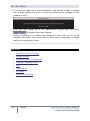
Table of Contents
G4K Power Quality Analyzer - System Overview .......................................... 6
Warranty ..................................................................................... 8
Acronyms ................................................................................... 10
Product Selection Guide ................................................................. 13
Preparation - Safety Precautions .......................................................... 16
What You'll Need .......................................................................... 18
Unpacking Components & Accessories ................................................. 19
The G4K BLACKBOX Unit ................................................................. 23
G4K Quick & Simple Installation ........................................................... 25
G4K BLACKBOX Unit Mounting ........................................................... 25
G4K Wiring ................................................................................. 28
Voltage Connections ................................................................... 32
Wiring the Current Connections ...................................................... 34
Connect the AC/DC Supply Terminal ................................................ 36
Connect the 48VDC Input.............................................................. 38
Establish 1st Time Connection .......................................................... 39
Confirm Operation ........................................................................ 41
G4K Unit Access ........................................................................... 43
G4K Quick Configuration ................................................................. 46
G4K Unit Setup.......................................................................... 47
Voltage & Frequency Configurations ................................................ 49
Currents.................................................................................. 51
Verify Measurement Readings ........................................................... 54
Access the Measurement Summary .................................................. 55
Verify Voltage & Current Readings .................................................. 57
Verify Power Readings ................................................................. 59
Enable PQZIP Recording .................................................................. 61
Monitoring Real-Time Data ................................................................. 63
Voltage & Current Measurements....................................................... 66
Averaging ................................................................................... 72
Power ....................................................................................... 76
Temperature ............................................................................... 80
2
ELSPEC
G4K Fixed Power Quality Analyzer
USER & INSTALLATION GUIDE
Phasors ..................................................................................... 82
Waveforms ................................................................................. 87
Voltage Flickering ......................................................................... 93
Pinst Waveform............................................................................ 96
Minimum / Maximum Flickering......................................................... 98
Voltage & Current Harmonics .......................................................... 101
P & Q Harmonics ......................................................................... 107
Spectrum .................................................................................. 113
Harmonics Table ......................................................................... 118
Voltage & Current, Min & Max Harmonics Table .................................... 121
PQ Min & Maximum Harmonics ......................................................... 124
About Power Quality Monitoring .......................................................... 127
PQ Compliance Summary ............................................................... 128
Compliance Information ................................................................ 132
Compliance Chart ........................................................................ 135
Events ...................................................................................... 138
PQZIP Recording - Principle ............................................................... 140
Default Settings .......................................................................... 142
PQZIP Recording - Configuration ....................................................... 143
Enabling / Disabling PQZIP ........................................................... 147
FIFO ..................................................................................... 149
Fixed Quality vs. Fixed Ratio ........................................................ 150
File Capacity ........................................................................... 153
FFT Mode ............................................................................... 155
Erase All PQZIP Data .................................................................. 157
About Energy ................................................................................ 159
Consumption & Demand ................................................................. 160
Detailed Information .................................................................... 162
Measurement Status ..................................................................... 164
About Instrument Settings ................................................................. 167
Device Setup .............................................................................. 168
Device - Info G4K Unit Configuration ............................................... 171
G4K Product Attributes ....................................................................................................... 173
Power Status ......................................................................................................................... 174
3
ELSPEC
G4K Fixed Power Quality Analyzer
USER & INSTALLATION GUIDE
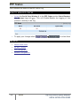
PoE Output ............................................................................................................................ 175
Alarms .................................................................................................................................... 176
Voltage & Frequency .................................................................. 177
Power Configuration ............................................................................................................ 179
Potential Transformer ......................................................................................................... 181
Smooth Filtering ................................................................................................................... 182
Voltage Polarity .................................................................................................................... 183
Define Nominal Values ........................................................................................................ 184
Time Settings .......................................................................... 186
Network Time ....................................................................................................................... 188
Time Setup ............................................................................................................................ 189
Daylight Saving ..................................................................................................................... 190
Currents................................................................................. 191
Current Transformer ............................................................................................................ 193
Nominal .................................................................................................................................. 194
Current Polarity .................................................................................................................... 195
Non-Measured Currents ....................................................................................................... 196
Communication Configuration ....................................................... 198
Security .................................................................................................................................. 199
About Network Setup........................................................................................................... 202
LAN 1 .................................................................................................................................. 204
LAN 2 / LCD Port Setup ................................................................................................... 206
Port Setup .......................................................................................................................... 208
Outer Access ..................................................................................................................... 210
Modbus TCP ....................................................................................................................... 211
DNP3 Configuration .......................................................................................................... 212
Status Summaries ............................................................................................................. 213
Serial Ports ............................................................................................................................ 215
RS-485 / RS-422 ................................................................................................................ 217
PPP Configuration ............................................................................................................ 219
PPP Status .......................................................................................................................... 220
Modem Configuration ...................................................................................................... 221
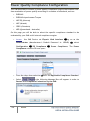
About Power Quality Compliance ................................................... 222
Power Quality Compliance Configuration ........................................................................ 223
User Defined Pages .............................................................................................................. 225
4
ELSPEC
G4K Fixed Power Quality Analyzer
USER & INSTALLATION GUIDE
User Defined Page 1......................................................................................................... 227
User Defined Page 2......................................................................................................... 232
User Defined Page 3......................................................................................................... 236
Advanced Settings .......................................................................... 239
System Log ................................................................................ 241
Creating Custom Events ................................................................. 244
Events List .............................................................................. 249
Create Event Conditions .............................................................. 251
Single Type Conditions ........................................................................................................ 253
Multiple Type Conditions .................................................................................................... 256
E-Mail Alerts .............................................................................. 258
Reports .................................................................................... 262
Energy Mode............................................................................ 264
Parameter Mode ....................................................................... 265
Energy Meter.............................................................................. 266
Display Setup ............................................................................. 269
Upgrade G4K Software - Firmware Upgrade ......................................... 272
Upgrade the FW Using FTP ........................................................... 275
Local FW Upgrade ..................................................................... 277
Optional Installations & Disconnections ................................................. 279
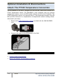
Attach The PT100 Temperature Connection ......................................... 279
Connect Power Over Ethernet ......................................................... 280
Detach the Voltage Terminal Block Connector ...................................... 281
About Elspec's Search Utility .............................................................. 282
Obtain Elspec's Search Utility .......................................................... 283
Use the Elspec's Search Utility ......................................................... 284
G4K Unit Access .......................................................................... 287
New Device Indication ................................................................... 291
Limitations of Elspec's Search Utility.................................................. 292
G4K Specifications .......................................................................... 293
G4K Physical Specifications............................................................. 299
5
ELSPEC
G4K Fixed Power Quality Analyzer
USER & INSTALLATION GUIDE
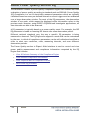
G4K Power Quality Analyzer - System Overview
The innovative design of the G4400 BLACKBOX device series is a technological
breakthrough providing the Perfect Permanent PQ Analysis solution. Its enhanced
capabilities are uniquely adaptable to address the individual needs & requirements
for almost any business and/or application. Empowered by the patented PQZIP
compression technology, the G4K can store up to a thousand times more than
other typical file formats. The PQZIP allows the G4K to continuously record &
store all electrical waveforms for extended periods with no gaps in the data. Its
superior accuracy yields a 2 x 16 Bit to yield, far surpassing IEC61000-4-30 Class A
requirements. The G4K features a threshold-free setup, & is equipped with
standard industrial protocols for seamless integration into any SCADA system. It
provides PQ parameters according to EN50160, IEC61000-4-30, & other national
standards, and the data may be analyzed over any network at any remote location.
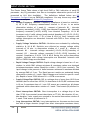
The advanced PQSCADA & Investigator Enterprise Analysis software enables the
operator to detect, view, control, analyze & isolate the minutest PQ anomaly for
the diagnosis & effective maintenance of equipment. It simplifies troubleshooting
& time-synchronized data recorded by any number of BLACKBOX devices, can be
compared within a particular site and/or across many sites.
The embedded Website serves as the main user-interface with the unit, providing
enhanced management, unit configuration & real-time monitoring of all
parameters.
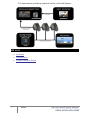
The optional G4100 Remote Display LCD Unit (RDU) is an integral part of the
Elspec Power Quality Data Center system, allowing inter-connectivity with the
G4400 series instruments for configuring and monitoring the electrical distribution
system. The G4100 connects and communicates with the G4400 BLACKBOX
devices directly via RJ45 network cable or through IP communication from
anywhere in the world. One RDU can be used to monitor and configure many
G4400 series instruments.
6
ELSPEC
G4K Fixed Power Quality Analyzer
USER & INSTALLATION GUIDE
The figure below provides a graphical outline of the G4K System:
SEE ALSO
7
Acronyms
G4K Warranty
Product Selection Guide
ELSPEC
G4K Fixed Power Quality Analyzer
USER & INSTALLATION GUIDE
Warranty
Each Elspec product is under warranty to be free from defects in material and
workmanship under normal use and service. The warranty period is for one year
and commences on the date of shipment. Parts, product repairs, and services are
under warranty for 90 days. This warranty extends only to the original buyer or
end-user customer and it does not apply to fuses, disposable batteries, or to any
product which, in Elspec's opinion, has been misused, altered, neglected,
contaminated, or damaged by accident or abnormal conditions in the operation or
handling of the product. Elspec warrants that the software will operate
substantially in accordance with its functional specifications for 90 days and that it
has been properly recorded on non-defective media. Elspec does not warrant that
the software will be error free and operate without interruption.
Elspec authorized re-sellers shall extend this warranty on new and unused products
to end-user customers only, but do not have authority to extend a greater or
different warranty on behalf of Elspec. Warranty support is available only if the
product is purchased through an Elspec authorized sales outlet or Buyer has paid
the applicable international price. Elspec reserves the right to invoice the Buyer
for any importation costs for the repair/replacement of parts when the product
purchased in one country is submitted for repair in another country.
Elspec’s warranty obligation is limited, at Elspec's option, to refund of the
purchase price, free of charge repair, or replacement of a defective product which
is returned to Elspec within the warranty period. For warranty service, contact
Elspec directly to obtain a return-authorization. On receipt of the authorization,
return the product to Elspec with a description of the problem, including prepaid
postage and insurance (FOB destination). Elspec assumes no risk for damage in
transit. Following warranty repair, the product will be returned to the Buyer,
transportation prepaid (FOB destination). If Elspec determines that the failure was
caused by neglect, misuse, contamination, alteration, accident, or abnormal
condition of operation of handling, including overvoltage failures caused by use
outside the product's specified rating, or normal wear and tear of mechanical
components, Elspec will provide an estimate of repair costs and obtain
authorization before commencing work. Following repair, the product will be
returned to the Buyer, transportation prepaid, and the Buyer will be billed for the
repair and return postage transportation charges (FOB Shipping Point).
This warranty is the Buyer's sole and exclusive remedy and is in lieu of all other
warranties, express or implied, including but not limited to any implied warranty
of merchantability or fitness for a particular purpose. Elspec shall not be liable for
any special, indirect, incidental, or consequential damages or losses, including loss
of data arising from any cause or theory.
Since some countries or states do not allow limitation of the term of an implied
warranty, or exclusion or limitation of incidental or consequential damages, the
limitations and exclusions of this warranty may not apply to every buyer. If any
provision of this Warranty is held invalid or unenforceable by a court or other
decision-maker of competent jurisdiction, such holding will not affect the validity
or enforceability of any other provision.
NOTICE REGARDING PROPRIETARY RIGHTS
This publication contains information proprietary to Elspec. By accepting & using
this manual, you agree that the information contained herein will be used solely
for the purpose of operating equipment developed & manufactured by Elspec.
SEE ALSO
9
System Overview
Acronyms
Product Selection Guide
ELSPEC
G4K Fixed Power Quality Analyzer
USER & INSTALLATION GUIDE
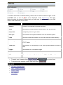
Acronyms
The following acronyms are being used within this document:
ACRONYM
DEFINITION
PQ
Power Quality
V
Voltage
F
Frequency
VN
Voltage Neutral
A
Ampere
CT
Current Transformer
PF
Power Factor
PT100
Platinum Resistance Thermometers
PU
Per Unit
PT
Potential Transformer (transformation ratio in both magnitude and
phase)
CT
Current Transformer
THD
Total Harmonic Distortion
HV
High Voltage
MV
Medium Voltage
LV
Low Voltage
ADC
Analog to Digital Converter
SSL
Secure Sockets Layer
GPS
Global Positioning System
UTC
Coordinated Universal Time
LAN
Local Area Network
CF
Compact Flash
ACRONYM
DEFINITION
OLP
OLE for Process Control (set of connectivity standards for industrial
automation)
OPC
Open Connectivity (formerly OLE for Process Control)
TCP
Transport Control Protocol
FTP
File Transfer Protocol
DHCP
Dynamic Host Configuration Protocol
DNP3
Distributed Network Protocol
PPP
Point to Point Protocol
PAP
Password Authentication Protocol
CHAP
Challenge Handshake Authentication Protocol
UART
Universal Asynchronous Receiver Transmitter
ISP
Internet Service Provider
INIT
Initialization (INIT String used in Modem)
AT
A command string should start with "AT" or "at", except for the commands
"A/" and "+++". At or aT are invalid
PST
Value measured over x period that characterizes the likelihood that the
voltage fluctuations would result in perceptible light flicker
THD
Total Harmonic Distortion
TDD
Total Demand Distortion
Ampl
Amplitude
FIFO
First In First Out
FFT
Fast Fourier Transform
csv
Comma Separated Values
11
ELSPEC
G4K Fixed Power Quality Analyzer
USER & INSTALLATION GUIDE
ACRONYM
DEFINITION
ELSPEC G4400 BLACKBOX DEVICE & ACCESSORIES
G4K
G4400 BLACKBOX Series of Power Quality Analyzers
PQZIP
Power Quality Data Compression & Archive File Format
PQSCADA
Power Quality Supervisory Control and Data Acquisition
RDU
G4100 Remote Display LCD Unit
CPU
G4K - Central Processing Unit Module
DSP
G4K - Digital Signal Processing Module
PS
G4K - Power Supply Module
FW
Firmware - G4K Software
SEE ALSO
12
System Overview
G4K Warranty
Product Selection Guide
ELSPEC
G4K Fixed Power Quality Analyzer
USER & INSTALLATION GUIDE
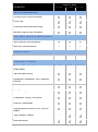
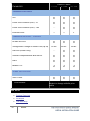
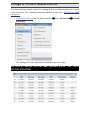
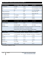
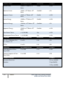
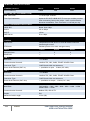
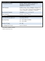
Product Selection Guide
The product selection guide will assist you in choosing the optimal G4K Power
Quality Analyzer that will suit your needs & requirements. The BLACKBOX device
series includes 3 products, namely the G4410, G4420 & G4430. They are mainly
differentiated by their measurement capabilities, storage capacity, PQ analysis &
communication ports.
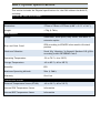
PRODUCT SERIES
CAPABILITIES
G4410 G4420 G4430
REAL-TIME MEASUREMENTS
Voltage Sampling Rate, Maximum Samples/Cycle
Voltage/Current
Unbalanced
-
Per
Phase,
256
512
1024
127TH
255TH
511TH
16/201
Bit
16/201
Bit
16/201
Bit
x2
x10
x10
Average,
Power: Real, Reactive, Apparent, Power Factor,
Frequency
Energy: Bidirectional, Total, Import, Export, Net
Demand: Block
Voltage Harmonics (Individual, Even, Odd, Total)
Up toType of Analog to Digital Converter
Measurement During Overloading (From Nominal)
CAPABILITIES
PRODUCT SERIES
G4410
G4420
G4430
With Ethernet Synchronization
50
50
50
With GPS Synchronization
1
1
1
128 MB
4 GB
16 GB
DATA & WAVEFORMS LOGS
Cycle-By-Cycle PQZIP Recording
Event Logs
Continuous Waveform Recording
Min/Max Logs For Any Parameter
TIME STAMPS, RESOLUTION (MICROSECONDS)
STORAGE CAPACITY
Internal Memory
POWER QUALITY ANALYSIS
Transient Detection, Microseconds
(50Hz/60Hz)
78.1/65.1µs 39/32.5µs 19.5/16.3µs
Sag/Swell Monitoring
Unbalance Components: Zero, Negative,
Positive
Flicker (IEC 61000-4-15)
Fast Flickering
Compliance Testing To EN50160
EN50160 Timestamps
Configurable for IEEE519-1992, IEEE159
(SEMI)
Time Stamps Of Above
Inter-Harmonics
___
CAPABILITIES
PRODUCT SERIES
G4420
G4430
1
2
2
10 sec.
25 sec.
25 sec.
G4410
COMMUNICATION PORTS
OPC
Power Over Ethernet (PoE) - In
Power Over Ethernet (PoE) - Out
Ethernet Ports
___
COMMUNICATION PORTS - CONTINUE
RS-485/422 Port
Voltage Ride Through on Power Loss (Up to)
USB Port (Power Only)
___
Onboard Comprehensive Web Server
DNP3
Modbus TCP
E-MAIL NOTIFICATIONS
SMTP Client
1
Effective Bits
Disclaimer: Outlined capabilities
subject to change without prior
notice
SEE ALSO
15
System Overview
Acronyms
G4K Warranty
ELSPEC
G4K Fixed Power Quality Analyzer
USER & INSTALLATION GUIDE
Preparation - Safety Precautions
WARNINGS
REVIEW THE ENTIRE MANUAL BEFORE USING THE INSTRUMENT AND ITS
ACCESSORIES
OBSERVE ALL WARNINGS AND CAUTIONS
DO NOT OPERATE THE INSTRUMENT AROUND EXPLOSIVE GAS OR VAPOR
AVOID WORKING ALONE
BEFORE USE, INSPECT THE INSTRUMENT, LEADS AND ACCESSORIES FOR
MECHANICAL DAMAGE, AND REPLACE WHEN DAMAGED
PAY SPECIAL ATTENTION TO THE INSULATION SURROUNDING THE
CONNECTORS AND PLUGS
REMOVE ALL ACCESSORIES THAT ARE NOT IN USE
MAKE SURE THE INSTRUMENT IS PROPERLY GROUNDED TO A PROTECTIVE
EARTH GROUND
DO NOT APPLY INPUT VOLTAGES ABOVE THE RATING OF THE INSTRUMENT
AS SHOWN ON THE NAME PLATE
DO NOT INSERT METAL OBJECTS INTO CONNECTORS AND OPENINGS
NEVER OPEN THE INSTRUMENT’S ENCLOSURE DURING OPERATION;
DANGEROUS VOLTAGES ARE PRESENT
USE THE INSTRUMENT ONLY AS SPECIFIED IN THIS MANUAL, OR THE
PROTECTION PROVIDED BY THE INSTRUMENT MAY BE IMPAIRED
DO NOT EXPOSE THE INSTRUMENT TO EXTREME MOISTURE AND OR RAIN
TO AVOID SHOCK OR FIRE
VERIFY THAT THE UNIT IS DISCONNECTED FROM THE MAIN POWER SUPPLY
INSPECT ALL ELECTRICAL AND MECHANICAL CONNECTIONS VISUALLY FOR
MECHANICAL DAMAGE AND INTEGRITY OF COMPONENTS AND ACCESSORIES
INSPECT CURRENT TRANSFORMER WIRING FOR PROPER DIRECTION THROUGH
THE CYLINDRICAL APERTURE OF THE CURRENT SAMPLING MODULE
PULL-TEST ALL CONTROL WIRING TO ENSURE SECURE SEATING IN
TERMINALS
BEFORE USE, INSPECT THE INSTRUMENT, LEADS AND ACCESSORIES FOR
MECHANICAL DAMAGE, AND REPLACE WHEN DAMAGED
DO NOT OPERATE THE INSTRUMENT OR ITS ACCESSORIES IF IT BECAME WET
FOR ANY REASON
16
ELSPEC
G4K Fixed Power Quality Analyzer
USER & INSTALLATION GUIDE
SEE ALSO
17
System Overview
What You'll Need
Unpacking Components & Accessories
G4K BLACKBOX Unit
G4K BLACKBOX Unit Mounting
ELSPEC
G4K Fixed Power Quality Analyzer
USER & INSTALLATION GUIDE
What You'll Need
Familiarize yourself with the G4K BLACKBOX Unit, Components & Accessories. In
addition, ensure that you follow the outlined Safety Precautions. You will need the
following tools & additional items for the initial installation:
Wire Strippers
Phillips Screwdriver
Flat Head Screwdriver
G4K BLACKBOX Unit, Components & Accessories
This User Guide
SEE ALSO
System Overview
Preparation – Safety Precautions
Unpacking Components & Accessories
G4K BLACKBOX Unit
Unpacking Components & Accessories
The G4K BLACKBOX is shipped from Elspec's factory in a sealed case to protect it
from damage during transportation. The small parts are shipped in a sealed bag
with the unit.
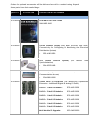
TO UNPACK THE UNIT & ITS ACCESSORIES
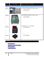
Remove the unit & all of the following components from the casing:
QUANTITY
ILLUSTRATION
DESCRIPTION & PART NUMBER
DEVICE, COMPONENTS & ACCESSORIES
1
G4K BLACKBOX Device
G4410 BLACKBOX: SPG-4410-0000
G4420 BLACKBOX: SPG-4420-0000
G4430 BLACKBOX: SPG-4430-0000
SEE ALSO
1
Voltage Terminal Block Connector (For
Sampling)
1
ENT-1005-0090
AC/DC Terminal Block Connector (For
Powering the Unit)
1
Product Selection Guide
ENT-1003-0192
RS485/422 Communication Terminal Block
(For Communication)
ENT-1004-0190
QUANTITY
1
ILLUSTRATION
DESCRIPTION & PART NUMBER
48VDC Terminal Block Connector (For Powering
the Unit)
1
Temperature Sensor Terminal Block Connector
(For PT100 Type)
1
ENT-1003-0190
Clamping Yoke Holder on Rail 35mm FM 4
1
ENT-1002-0190
MAL-2000-5002
Installation & Demonstration Disc
SMX-0408-0100
Orders for optional accessories will be delivered as well in a sealed casing. Unpack
these parts from their sealed bags:
QUANTITY
ILLUSTRATION
DESCRIPTION & PART NUMBER
OPTIONAL ACCESSORIES
As Ordered
BLACKBOX Full User Guide
SMX-0602-0100
As Ordered
G4100 Remote Display LCD Unit (Provide G4K InterConnectivity for Configuring & Monitoring the Electrical
Distribution System)
As Ordered
GPS (Global Position
Synchronization)
As Ordered
System)
(For
Mobile
Time
SOA-0232-0400
Multi-Frequency 3.5G Wireless Modem (For Fast Mobile
Communication Access)
As Ordered
SPG-4100-0090
SCM-0001-0000
G4400 Multi IO Expansion (For Monitoring Capabilities
Extension - Additional Digital & Analog IO Ports)
G4430 + 1 Multi IO Module:
SPG-4431-0090
G4430 + 2 Multi IO Modules:
SPG-4432-0090
G4420 + 1 Multi IO Module:
SPG-4421-0090
G4420 + 2 Multi IO Modules:
SPG-4422-0090
G4410 + 1 Multi IO Module:
SPG-4411-0090
G4410 + 2 Multi IO Modules
SPG-4412-0090
Multi Module IO Upgrade:
SOC-0400-0090
QUANTITY
ILLUSTRATION
DESCRIPTION & PART NUMBER
OPTIONAL ACCESSORIES
Protective Metal Cabinet (IP54) with wiring (H x W x
D) - 50 x 50 x 30cm (19.7 x 19.7 x 11.8") :
As
Ordered
SOA-0002-0000
Polycarbonate Enclosure (IP54) with wiring (H x W x
D) - 50 x 50 x 30cm (19.7 x 19.7 x 11.8") :
As
Ordered
SOA-0003-0000
As
Ordered
200W Heater with Thermostat:
As
Ordered
RJ45/Fiber Optic Converter:
SOA-0101-0000
SOC-0401-0000
SEE ALSO
22
System Overview
Preparation – Safety Precautions
What You'll Need
G4K BLACKBOX Unit
ELSPEC
G4K Fixed Power Quality Analyzer
USER & INSTALLATION GUIDE
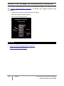
The G4K BLACKBOX Unit
The innovative design of the G4K BLACKBOX has been uniquely adapted to address
the individual needs & requirements for almost any business and/or application.
The modular & expandable design provides maximum flexibility for customized
requirements.
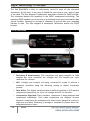
The main base (front end) of the unit is comprised of three modules namely the
Central Processing Unit (CPU), the Digital Signal Processing (DSP), & the Power
Supply (PS).
The functions for the CPU are mainly data compression, file handling & facilitation
of communication interfaces. The CPU features an AC/DC power supply, DC/DC
converter, an automatic selection of highest voltage & an ultra capacitors' ridethrough for up to 25 seconds.
The DSP is responsible for capturing the electric signal & converting the waveforms
to digital data. The DSP's capabilities include simultaneous 12 channel sampling at
250 kHz (4 µsec), full scale measurements 10 x from nominal voltages & currents at
an extremely high accuracy. The CT's dual range with auto selection ranges from 0
- 5A, 0 - 50A RMS & has a reading accuracy of 0.1%. There are a total of six (6)
apertures. Typically only the first four (4) are used as current inputs for I1, I2, I3,
and IN (Neutral current optional as the fourth input).
The PS facilitates a wide range of inputs that comply with the highest standards
set by the industry. The power supply module contains internal backup circuitry to
hold internal voltage during momentary transients and disturbances. Thus, when
powering off the unit, it continues operating for up to 1 minute. The power supply
supports the following power sources:
DC 100-300V
AC 100-260V, 60/50 Hz (recommended)
PoE 48V
The top of this front end base facilitates the connection for the PT100
thermostat & the DC Converter input. In addition to the PT100 connection, the
G4K is equipped with 2 additional internal temperature sensors (PS and DSP
modules). The operating temperature ranges from -20 to +70°C & the storage
temperature ranges from -30 to +80°C. The DC Converter ranges from an input DC
of 48 VDC & a minimum voltage for PoE of 48 VDC.
23
ELSPEC
G4K Fixed Power Quality Analyzer
USER & INSTALLATION GUIDE
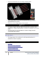
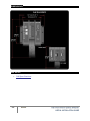
Physical layout of the 3 modules including the location of the system
connectors for both the Front & Top View:
SEE ALSO
System Overview
Preparation – Safety Precautions
What You'll Need
Unpacking Components & Accessories
G4K Quick & Simple Installation
This section contains the installation & setup procedure for the G4K BLACKBOX
that is quick & simple to follow. After you have installed your G4K device, you can:
Monitor the Quality of your Electrical Power,
Monitor PQ Parameters according to EN50160, IEC61000-4-30 & Customized
Standards
Store a thousand times more than other typical file formats with PQZIP
G4K - QUICK & SIMPLE INSTALLATION
The procedure includes:
Mounting the G4K BLACKBOX
Wiring the G4K BLACKBOX
Connecting the G4K BLACKBOX
Confirming the G4K's Operation
G4K Unit Access via Elspec's Web Interface
Configuring the G4K Device
Verifying Measurement Readings
Enabling PQZIP Recording
WARNING
Before you start, ensure that the panel is de-energized & that you take
the necessary Safety Precautions!
G4K BLACKBOX Unit Mounting
The G4K BLACKBOX is intended to be mounted within an enclosure, or can be
fastened either to a DIN Rail or to a Flat Surface. The physical dimensions of the
G4K are: 17.5 x 23.2 x 13.8cm (6.9 x 9.1 x 5.4”) & it weighs 1.7Kg (3.7lbs).
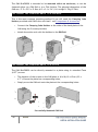
FASTENING THE G4K BLACKBOX TO A DIN RAIL
This is the most common mounting method & you will need the Clamping Yoke
Holders provided with G4K & the unit itself - see Components & Accessories.
Connect the Clamping Yoke Holders to the sides of the back plate of the
G4K using the 2 screws provided,
Attach the entire unit with the holders to the DIN Rail:
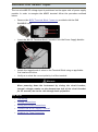
FASTENING THE G4K BLACKBOX TO A PLATE
The G4K BLACKBOX can be directly mounted to a plate using 4 x standard 7mm
(0.27”) screws.
The distance of the screws on the G4K plate is (H x W) 10 x 12cm (3.9 x
4.7”). Ensure the plate has corresponding holes,
Simply screw the G4K unit onto the plate at the corresponding holes:
Successfully Mounted G4K Unit
26
ELSPEC
G4K Fixed Power Quality Analyzer
USER & INSTALLATION GUIDE
SEE ALSO
27
Installation
G4K Wiring BLACKBOX
Establish 1st Time Connection
Confirm Operation
G4K Unit Access
G4K Configuration
Verifying Measurement Readings
Enable PQZIP Recording
ELSPEC
G4K Fixed Power Quality Analyzer
USER & INSTALLATION GUIDE
G4K Wiring
The DSP Module of the G4K receives analog signals and converts them to digital
signals to be measured and stored for further process and analysis. An essential
part of the G4K Wiring Procedure is the Power Configuration, which is configured
in the Web Interface. Included in this section are the types of Power Topology the
G4K supports that will be important to understand prior to proceeding with:
Connecting the Voltage Connections
Connecting the Current Connections
Connecting the AC/DC Supply Terminal
Connecting the 48 VDC Input
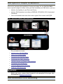
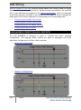
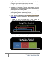
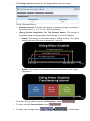
G4K BLACKBOX POWER TOPOLOGY SUPPORTS
The G4K BLACKBOX is designed to serve in virtually any power topology
configuration. The diagrams below outline the types of topologies with their
applicable Configuration in Elspec's Web Interface:
28
Single LN Configuration:
Single LL Configuration:
ELSPEC
G4K Fixed Power Quality Analyzer
USER & INSTALLATION GUIDE
29
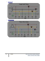
2Phase TR:
Delta 3 Wires:
ELSPEC
G4K Fixed Power Quality Analyzer
USER & INSTALLATION GUIDE
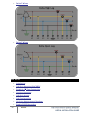
WYE 4 Wires:
WYE 4 Wires:
Delta 3 Wires:
Delta 3 Wires:
SEE ALSO
31
Installation
G4K Unit Mounting BLACKBOX
Establish 1st Time Connection
Confirm Operation
G4K Unit Access
G4K Configuration
Verifying Measurement Readings
Enable PQZIP Recording
ELSPEC
G4K Fixed Power Quality Analyzer
USER & INSTALLATION GUIDE
Voltage Connections
Five terminals are available for the voltage sampling inputs on the DSP Module of
the G4K. They are marked as L1, L2, L3, N, &
. Each of the 4 inputs (V1, V2,
V3, N) are capable of receiving electrical signals of up to 1KV continuous RMS (up
to 8KV transient). In order to wire voltage connections, follow the following
procedure:
32
Install an over current device on the AC phase lines:
Remove the Voltage Terminal Block Connector provided with the G4K Unit:
ELSPEC
G4K Fixed Power Quality Analyzer
USER & INSTALLATION GUIDE
Insert the terminal block into the Voltage Sampling inputs:
Attach lugged ends of wires to the terminal block securing it with an
applicable sized screw driver,
Verify the correct voltage polarity of the terminal.
WARNING
You need to install a 2A Fuse and/or Circuit Breaker in series to the
instrument’s Voltage Sampling Input Terminals according to local wiring
codes.
Powering down the instrument does not remove voltage from the
voltage sampling terminals.
NOTE NOTE NOTE ...
The Ground input is the reference for all channels therefore it is
essential to connect it properly.
SEE ALSO
33
G4K Wiring
Wiring the Current Connections
Connect the AC/DC Supply Terminal
Connect the 48VDC Input
Establish 1st Time Connection
ELSPEC
G4K Fixed Power Quality Analyzer
USER & INSTALLATION GUIDE
Wiring the Current Connections
Electric current is sampled as it flows through cylindrical apertures in the circular
section of the centrally mounted Digital Signal Processing (DSP) Module. There are
a total of six (6) apertures. Typically only the first four (4) are used as current
inputs for I1, I2, I3, and IN (Neutral current optional as the fourth input).
Optionally, a fifth aperture may be ordered for an additional current input, and
the sixth aperture is disabled at this stage. To wire current connections:
34
Install Current Transformers in series ahead of the unit
Feed the current lines through the cylindrical apertures in the circular
section of the G4K's DSP Module:
Verify the polarity of current conductors with the arrows on the circular
section of the DSP
ELSPEC
G4K Fixed Power Quality Analyzer
USER & INSTALLATION GUIDE
G4K Successful Current Wiring
WARNING
Current Transformer outputs must be short circuited to prevent them
from getting damaged. Dangerous voltages exist between the two output
leads.
SEE ALSO
35
G4K Wiring
Voltage Connections
Connect the AC/DC Supply Terminal
Connect the 48VDC Input
Establish 1st Time Connection
ELSPEC
G4K Fixed Power Quality Analyzer
USER & INSTALLATION GUIDE
Connect the AC/DC Supply Terminal
The AC terminal may be fed with either AC or DC voltage. The procedure to wire
both is the same and has the following limits:
AC: 80 to 260V @ 50/60Hz
DC: 110 to 300V / 35Watt
CONNECTING THE AC/DC SUPPLY TERMINAL:
Install an Over-current Protection device on the AC phase line side before
the unit:
Remove the AC/DC Terminal Block Connector provided with the G4K
BLACKBOX unit:
Insert the terminal block into the Power Supply Terminal:
Attach the bared ends of wires to the AC/DC terminal block connector using
the correct sized flat-head screwdriver
Verify the correct polarity of the terminal
WARNINGS
It is recommended to install a 2A fuse & or circuit breaker in series to
the instrument terminals according to local wiring codes.
When powering down the instrument by closing the circuit breaker,
internal low voltage remains on the instrument terminals, and
consequently on the downstream side of the circuit breaker for 25
seconds, due to the ride through back up feature.
SEE ALSO
37
G4K Wiring
Voltage Connections
Wiring the Current Connections
Connect the 48VDC Input
Establish 1st Time Connection
ELSPEC
G4K Fixed Power Quality Analyzer
USER & INSTALLATION GUIDE
Connect the 48VDC Input
The two wire 48V DC voltage input is positioned on the upper side of power supply
module. In order to energize the 48VDC terminal follow the procedure outlined
below:
Remove the 48VDC Terminal Block Connector provided with the G4K
BLACKBOX unit:
Insert the 48V DC Terminal Block Connector into the Power Supply Module:
Attach the lugged ends of wires to the Terminal Block using an applicable
flat head screw driver
Verify as to what the correct polarity is of the terminal
WARNING
When powering down the instrument by closing the circuit breaker,
internal voltage remains on the downstream side of the circuit breaker
for 25 seconds, due to the ride through back up feature.
SEE ALSO
G4K Wiring
Voltage Connections
Wiring the Current Connections
Connect the AC/DC Supply Terminal
Establish 1st Time Connection
Establish 1st Time Connection
In order to establish communication between your G4K & the Network Server, the
device may be connected using the LAN1 Port directly to an existing local LAN (if
one exists). Alternatively, you may connect the device directly to the PC to
establish initial communication.
CONNECT THE DEVICE TO THE LOCAL NETWORK
Simply connect a RJ145 LAN Network Cable to the LAN1 Port on the G4K's
CPU Module to your LAN Local Network Outlet:
CONNECT THE G4K DIRECTLY TO THE PC
Disconnect the network cable linking your PC/Laptop to the server network
Using the same cable (RJ45 LAN Network Cable), connect to the port
marked LAN1 G4K's CPU Module:
The green link-LED of the LAN1 connector begins to flash as Windows begins
communicating with the unit
Wait for about 2 minutes as the Windows operating system reverts to the
default "No Server" IP configuration
When this is completed, the "Local Area Connection Status" icon in the
"Quick Start" tray will change to "Limited or no connectivity":
SEE ALSO
40
Installation
G4K Unit Mounting BLACKBOX
G4K Wiring BLACKBOX
Confirm Operation
G4K Unit Access
G4K Configuration
Verifying Measurement Readings
Enable PQZIP Recording
ELSPEC
G4K Fixed Power Quality Analyzer
USER & INSTALLATION GUIDE
Confirm Operation
Confirm that your G4K Device is operating & that all the connections are working
with the following indicators:
Turn on the power supplying the unit
The LEDs on the power supply light up:
Verify the unit is operating correctly with reference to the following table:
LED
DESCRIPTION
G4K PS Module: Green signals that external power exists. Red signals
external power is out; unit will soon cease to function (25 seconds max.)
G4K DSP Module: Blinking green signals normal operation and system boot
G4K Main CPU Module: Green signals normal operation
Blinking Red: During Shutdown process
Constant Red: While Alarm is active (based on Alarm Configuration) may
signal malfunction.
NOTE NOTE NOTE ...
After powering up, wait at least one minute until the startup process is
complete
The red indicator light will remain on until the PQZIP is enabled by the user.
See Also: Enable PQZIP Recording
SEE ALSO
Installation
G4K Unit Mounting BLACKBOX
G4K Wiring BLACKBOX
Establish 1st Time Connection
G4K Unit Access
G4K Configuration
Verifying Measurement Readings
Enable PQZIP Recording
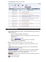
G4K Unit Access
Once you have Connected the Device for the 1st Time, you may access your G4K
Unit by simply clicking the WEB Hyperlink button in your Elspec's Search Utility.
Alternatively you can simply access the device directly via Internet Explorer by
inserting the Device's IP address directly (address is also indicated in Elspec's
Search Utility). The Default IP Address for a newly supplied G4K unit is:
169.254.249.247.
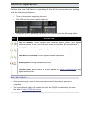
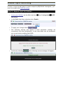
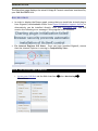
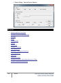
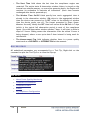
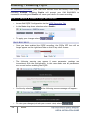
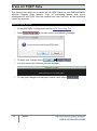
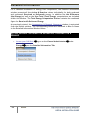
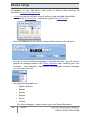
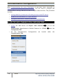
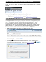
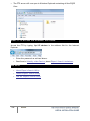
ACCESS ELSPEC'S SEARCH UTILITY:
After you have Copied the Utility on your Desktop, access it by clicking on the
Elspec's Search Icon:
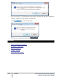
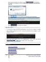
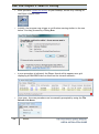
Initially, the program may trigger a verification warning similar to the one
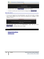
below. You may proceed by clicking Run
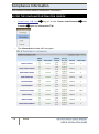
A scan procedure is initiated; the Elspec Search utility appears as a grid
displaying all BLACKBOX devices found on the intranet network:
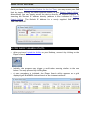
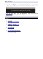
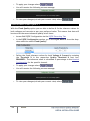
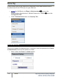
ACCESS INSTRUMENT VIA THE WEB HYPERLINK (RECOMMENDED):
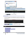
Select the Web link for your device, Elspec's Web Interface will now open:
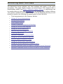
In order to view the different languages in the Web Interface, you will need to
upload the language feature from Elspec's Website when installing your new
Firmware. Once uploaded, simply select the applicable interface language
from the drop-down list:
The supported languages are:
English (Default)
Russian
German
Spanish
French
Chinese
(For other languages – please contact your local Elspec distributor)
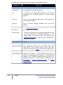
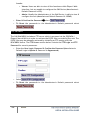
The Password field defines user level/privileges. The user levels are Viewer
/ Administrator (See Security Settings). The default password including
privileges for each level are:
Viewer is 123 (Read only, can choose interface language only, no
operations related changes are allowed)
Administrator is 12345 (Administration, setup & full control)
NOTE NOTE NOTE
The Website is optimized to work with Internet Explorer 7, 8 or 9 in
“Compatibility View”.
Ensure that the Internet Explorer is running in
Compatibility View:
Other web browser applications can limit some functionality and/or show an
incorrect layout.
For local networking the browser should be configured as working without a
proxy server. Refer to Disable Proxy Server in Internet Explorer.
Should you be running Skype simultaneously with Elspec’s Search, you will not
be able to access the device via the Web Link. Close Skype & access Elspec’s
Search again to follow the Web Link.
The passwords above are factory default values. You are advised to modify
Admin password if extended security measures are required (See Security
Settings).
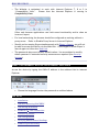
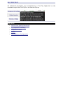
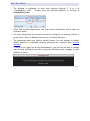
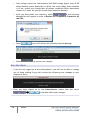
DIRECT INSTRUMENT ACCESS VIA INTERNET EXPLORER
Access the device by typing the G4K's IP address in the address field in Internet
Explorer:
Choose the language & enter the password as outlined above
SEE ALSO
Installation
G4K Unit Mounting BLACKBOX
G4K Wiring BLACKBOX
Establish 1st Time Connection
Confirm Operation
G4K Configuration
Verifying Measurement Readings
Enable PQZIP Recording
G4K Quick Configuration
This section focuses only on the major configurations needed for initial installation
of your G4K device. For a more detailed & comprehensive procedure see
Instrument Settings. This procedure includes a quick & simple configuration
procedure for your:
G4K Unit
Voltage & Frequency
Currents
SEE ALSO
Installation
G4K BLACKBOX Unit Mounting
G4K Wiring BLACKBOX
Establish 1st Time Connection
Confirm Operation
G4K Unit Access
Verifying Measurement Readings
Enable PQZIP Recording
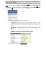
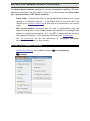
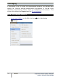
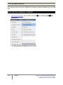
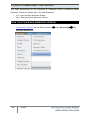
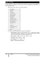
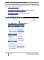
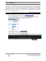
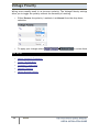
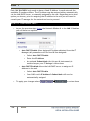
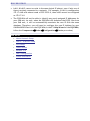
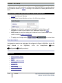
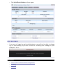
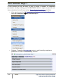
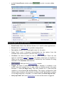
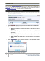
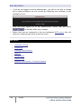
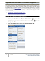
G4K Unit Setup
Access your G4K Device via Elspec's Web Interface
log on as the Administrator
(Manufacturer’s Default Passwords are: 12345 (Admin), & 123 (Viewer))
Configuration
under
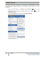
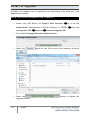
Device Setup select the Device Info Tab:
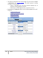
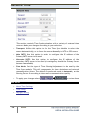
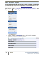
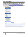
In the G4 Unit Configuration Section complete:
Site Name: Enables the user to include a description of the site
where the device is installed. This site description also appears in the
Elspec's Search utility under Unit Description when searching for
devices
Description: An additional text field for you to use optionally as you
see fit
Operator: A text field for inputting an operator/technician’s name
Company: A text field for inputting company’s name
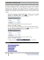
To apply your changes select
NOTE NOTE NOTE
If you are not logged on as the Administrator, you will not be able to change
any of these settings & you will receive the following error message in your
attempt to do so:
Once you have signed on at the Administrator ensure that you select
to affect your changes.
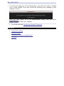
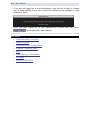
Go to the next step Configuring Voltage & Frequency
SEE ALSO
Instrument Settings
G4K Unit Setup
Voltage & Frequency Configurations
Currents
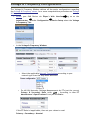
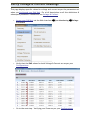
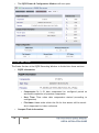
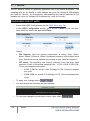
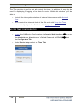
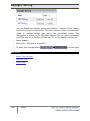
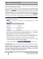
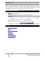
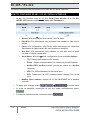
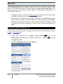
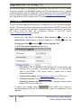
Voltage & Frequency Configurations
The Voltage & Frequency Window defines all the major configurations regarding
the Voltage & Frequency values, for a more comprehensive procedure see Voltage
& Frequency.
Access your G4K Device via Elspec's Web Interface
Administrator
under Configuration
& Frequency Tab:
log on as the
Device Setup select the Voltage
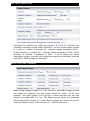
In the Voltage & Frequency Window:
Select the applicable Network Type Settings according to your
network type from the drop-down selection:
For MV/HV Networks (Voltage Measurements by PT's) set the correct
Primary & Secondary Ratio (with / ) – according to the PT
Manufacturer's Specifications & not just the Ratio:
If the PT Ratio is inapplicable, then set your values to read:
Primary = Secondary = Nominal
Define the Nominal Values for Frequency (F) and Voltages (V) (with / ):
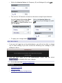
The ratio for LV Networks is based on the same concept & specifications Set the Primary & Secondary Ratio
(with / ) (according to the PT
Manufacturer's Specifications & not
just the Ratio):
Define the Nominal Values for
Frequency (F) and Voltages (V) (with
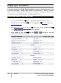
/ ):
To apply your changes select
NOTE NOTE NOTE
If you are not logged on as the Administrator, you will not be able to change
any of these settings & you will receive the following error message in your
attempt to do so:
Once you have signed on at the Administrator ensure that you select
to actually affect your changes.
Go to the next step Current Configuration
SEE ALSO
Instrument Settings
G4K Unit Setup
Voltage & Frequency Configurations
Currents
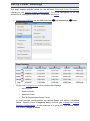
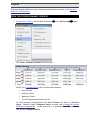
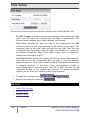
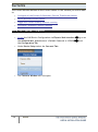
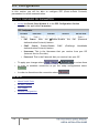
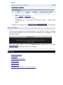
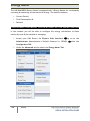
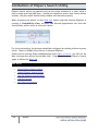
In the Current Window you will be able to define all the major configurations for
the Current Values, for a more comprehensive procedure see Currents.
Access your G4K Device via Elspec's Web Interface
log on as the
Administrator (Manufacturer’s Default Password is: 12345)
Configuration
under
Device Setup select the Currents Tab:
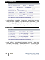
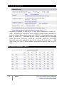
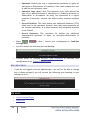
In the Currents Window:
Set the correct Primary & Secondary Transformation Ratios for all
the Current channels from I 1 to I N (with / ) - according to the CT
Manufacturer's Specifications & not just the Ratio:
Define the Nominal Values for all the Current Channels from I 1 to I N
(with / ):
If the CT Ratio is inapplicable, then set your values to read:
Primary = Secondary = Nominal
52
To apply your changes select
ELSPEC
G4K Fixed Power Quality Analyzer
USER & INSTALLATION GUIDE
NOTE NOTE NOTE
The Nominal Values define both the Event Level as well as the measurement
range. The maximum measured value is 16 times the nominal.
If you are not logged on as the Administrator, you will not be able to change
any of these settings & you will receive the following error message in your
attempt to do so:
Once you have signed on at the Administrator ensure that you select
to actually affect your changes.
SEE ALSO
Instrument Settings
G4K Unit Setup
Voltage & Frequency Configurations
Verify Measurement Readings
The final step after you have Configured your Device, is to verify the voltage &
current measurements of your G4K Unit. This verification step covers only a partial
section of the G4K's Full PQ Monitoring Capabilities. It includes:
Accessing & Reviewing the Measurement Summary
Monitoring Voltage & Current Measurements
Monitoring the Power
SEE ALSO
Installation
G4K Unit Mounting BLACKBOX
G4K Wiring BLACKBOX
Establish 1st Time Connection
Confirm Operation
G4K Unit Access
G4K Configuration
Enable PQZIP Recording
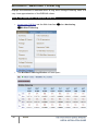
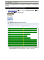
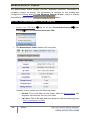
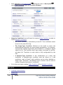
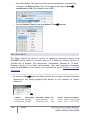
Access the Measurement Summary
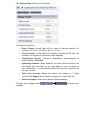
The Measurement Summary summarizes all your measurement readings. The most
important parameters you will need to focus on in this window are Phase Order
(for 3 phase systems) & DSP Synchronization:
Phase Order: Confirms the order of the voltage phases starts from V 1 & are
moving in a clockwise direction. If the Phase Order is incorrect (not 123)
recheck your Voltage Connections & that they are connected in the correct
order.
DSP Synchronization: Confirms that the unit is synchronized with the
signals of the device. If this is ON it means that the device is reading all the
signals in a synchronized manner, & if it is OFF it means that the device is
not reading the signals. In this instance recheck all your Connections.
See PQ Monitoring for all the definitions & subsequent parameter
calculations that appear on this window.
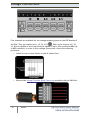
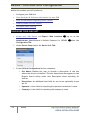
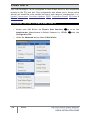
ACCESS THE SUMMARY WINDOW
Access your G4K Unit via the Web Interface
Summary:
Open Monitoring
The Summary Window will now open:
See explanation on
Phase Order above.
See explanation on
DSP Synchronization
above.
SEE ALSO
56
Verify Measurement Readings
Verify Voltage & Current Readings
Verify Power Readings
About PQ Monitoring
ELSPEC
G4K Fixed Power Quality Analyzer
USER & INSTALLATION GUIDE
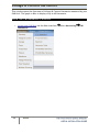
Verify Voltage & Current Readings
This page displays specific values for voltage and current as per the parameters set
when you Configured your G4K Unit. For a full description on all the definitions &
subsequent parameter calculations see Voltage & Current.
Open Monitoring
Voltage
Access your G4K Unit via the Web Interface
& Current:
Verify that the RMS values for both Voltage & Current are as per your
Configurations:
Go to the next step - Verifying your Power as per your Configurations
SEE ALSO
58
Verify Measurement Readings
Access the Measurement Summary
Verify Power Readings
About PQ Monitoring
ELSPEC
G4K Fixed Power Quality Analyzer
USER & INSTALLATION GUIDE
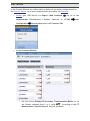
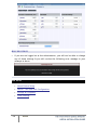
Verify Power Readings
This page displays specific values for the different Electrical Power Parameters
relevant to the Specific Power Configuration. For a full description on all the
definitions & subsequent parameter calculations see Power.
Open Monitoring
Access your G4K Unit via the Web Interface
Verify your Configurations in this window that displays:
Active Power
Reactive Power
Apparent Power
True & Displacement Power Factor
Power:
In most network configurations the Active Power will reflect a Positive
Value. Should it have a Negative Value, recheck your Voltage & Current
Polarity Configuration. In the presence of a generator, the Active Power
will reflect a Negative Value.
SEE ALSO
Verify Measurement Readings
Access the Measurement Summary
Verify Voltage & Current Readings
About PQ Monitoring
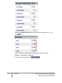
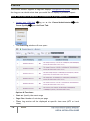
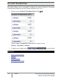
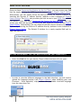
Enable PQZIP Recording
In order to record actual data for further analysis by PQSCADA & Investigator, you
must first enable the PQZIP Recording.
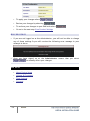
HOW TO ENABLE PQZIP RECORDING
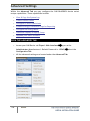
Open Configuration
PQZIP
Access your G4K Unit via the Web Interface
Recording
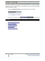
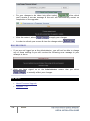
In the State drop-down selection select Enable:
To apply your changes select
The following warning may appear if some parameter readings are
inconsistent with the configuration. In this case make sure all parameters
are correct before enabling the PQZIP:
Confirm by selecting
& the following success message will appear:
NOTE NOTE NOTE
If you are not logged on as the Administrator, you will not be able to change
any of these settings & you will receive the following error message in your
attempt to do so:
Once you have signed on at the Administrator ensure that you select
to actually affect your changes.
SEE ALSO
Installation
G4K Unit Mounting BLACKBOX
G4K Wiring BLACKBOX
Establish 1st Time Connection
Confirm Operation
G4K Unit Access
G4K Configuration
Verifying Measurement Readings
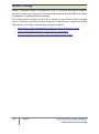
About PQ Monitoring
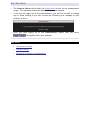
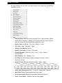
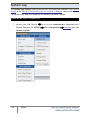
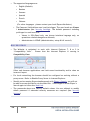
Monitoring Real-Time Data
The Monitoring section displays real time readings and graphs of the grid’s
parameters. The graph display requires an ActiveX plug-in from Gigasoft that is
downloadable either from Elspec's Website's Support Section or alternatively can
be installed directly from your BLACKBOX CD. The ActiveX plug-in allows different
view options needed for your PQ Monitoring. In the PQ Monitoring Section you will
be able to monitor the following PQ measurements of your G4K Unit:
Total measurements in the Summary Window
Voltage & Current Measurements
Average Measurements
Power Measurements
Internal & External Temperature Readings
Voltage & Current Phase Diagrams
Voltage & Current Waveforms
Short & Long Term Voltage Flickering
Flickering Waveforms
Minimum & Maximum Flickering Values
Voltage & Current Harmonics Spectrum
Active & Reactive Harmonic Powers
Voltage & Current Sub & Inter-Harmonics
Voltage & Current Harmonics in Values & Angles
Minimum, Maximum Values & Angles of Voltage & Current Harmonics
Minimum & Maximum Values of Active & Reactive Power Harmonics
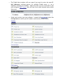
ACCESS THE PQ MONITORING SUMMARY
Access your G4K Unit via the Web Interface
Open Monitoring
Summary:
The Summary & Synchronization Status Window will now open:
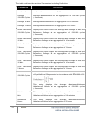
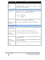
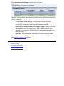
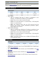
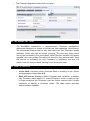
The table outlines the sections' Parameters including Definition:
PARAMETER
DEFINITION
SUMMARY WINDOW
Frequency
The number of cycles per second
I AVG
The current in a single phase system or the current
averaged over all three phases in a three phase
system
V(LL) AVG
Line to line voltage averaged over all three phases in
a three phase system
V(LN) AVG
Line to neutral voltage averaged over the three
phases
Power
Factor TOTAL
Total True Power Factor over three phases, averaged
by default over 1 minute
Phase Order
Confirms the order of the voltage phases starts from
V 1 & are moving in a clockwise direction. If the
Phase Order is incorrect (not 123) recheck your
Voltage Connections & that they are connected in
the correct order
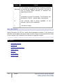
SYNCHRONIZATION STATUS
65
Time
Synchronization
Indicates the connection quality to the time source.
This connection supplies the instrument with world
time (UTC) from a time source. The Time Sync
quality is essential to PQZIP coherent file generation
DSP
Synchronization
Confirms that the unit is synchronized with the
signals of the device. If this is ON it means that the
device is reading all the signals in a synchronized
manner, & if it is OFF it means that the device is not
reading the signals. In this instance recheck all your
Connections, Network Communication, & Device
Configurations.
ELSPEC
G4K Fixed Power Quality Analyzer
USER & INSTALLATION GUIDE
Voltage & Current Measurements
This page displays specific values for Voltage & Current Measurements at a 10/12
cycle resolution. The viewed parameters depend on how your G4K Unit has been
Configured.
select Monitoring
Access your G4K Unit via the Web Interface
& Current:
The Voltage & Current PQ Monitoring Window will now open
Voltage
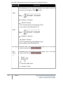
VOLTAGE & CURRENT SECTION (RMS, MIN/MAX VALUE, THD, CREST
FACTOR, K FACTOR)
The table outlines the sections' Parameters including Definition:
PARAMETER
PU
DEFINITION
By selecting PU (Per Unit) will present the values as part of
nominal (for example: 230V
100.0%)
VRMS
= Number of Samples
= Specific Channel
10/12 Continuous Non-Overlapping Cycles
In Accordance with IEC61000-4-30
ARMS
= Number of Samples
= Specific Channel
10/12 Continuous Non-Overlapping Cycles
In Accordance with IEC61000-4-30
Min Value
Minimum RMS value since the initial power up or the most
recent selection of:
Max
Value
Maximum RMS value since the initial power up or the most
recent selection of:
THD
C = Harmonic RMS Value
n = Harmonic Order
67
ELSPEC
G4K Fixed Power Quality Analyzer
USER & INSTALLATION GUIDE
PARAMETER
DEFINITION
V Crest
Factor
Measures Ratio Between the VPEAK and VRMS
A Crest
Factor
Measures ratio between the IPEAK & ARMS
K-Factor
Where
TH
is the Harmonic #, and
is the RMS value of the
Harmonic
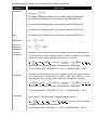
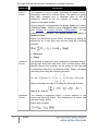
VOLTAGE & CURRENT SECTION (TDD, THD EVEN, THD ODD, OVERDEVIATION, UNDER DEVIATION)
The table outlines the sections' Parameters including Calculation:
PARAMETER
TDD
DEFINITION
Total Demand Distortion – TDD – is the current distortion
(harmonics above the 1st) as a percent of maximum demand load.
TDD is defined using the following relationship:
THD Even
C = Harmonic RMS Value
n = Harmonic Order
THD Odd
C = Harmonic RMS Value
n = Harmonic Order
OverDeviation
UnderDeviation
The Over-Deviation indicates how much higher the RMS Voltage is
than the Reference Voltage
The Under-Deviation indicates how much lower the RMS Voltage is
than the Reference Voltage
UNBALANCE SECTION (AVG, MIN, MAX)
The table outlines the sections' Parameters including Calculation:
PARAMETER
DEFINITION
Unbalance
The Supply Voltage Unbalance is Evaluated Using the Method of
Symmetrical Components in Accordance with IEC61000-4-30
Unbalance Avg.
The Average Supply Voltage Unbalance is Evaluated Using the Method
of Symmetrical Components in Accordance with IEC61000-4-30
Unbalance Min.
The Minimum Supply Voltage Unbalance is Evaluated Using the Method
of Symmetrical Components in Accordance with IEC61000-4-30
Unbalance
Max.
The Maximum Supply Voltage Unbalance is Evaluated Using the Method
of Symmetrical Components in Accordance with IEC61000-4-30
Zero Sequence
Unbalance
Negative
Sequence
Unbalance
Positive
Sequence
Defined as the symmetrical vector system derived by application of
the Fortescue’s transformation matrix, and that rotates in the same
direction as the power frequency voltage (or current):
U1 =
(U a +
Ub +
Uc) where
and Ua, Ub, Uc
and are line to neutral voltages (fundamental component)
In Accordance With IEC61000-3-13, ed. 1.0 (2008-02) Ref: 3.26.3
Negative
Sequence
Defined as the symmetrical vector system derived by application of
the Fortescue’s transformation matrix, and that rotates in the
opposite direction to the power frequency voltage (or current):
U1 =
(U a +
Ub +
Uc) where
and Ua, Ub, Uc
and are line to neutral voltages (fundamental component)
In Accordance With IEC61000-3-13, ed. 1.0 (2008-02) Ref: 3.26.4
Zero
Sequence
Defined as the in-phase symmetrical vector system derived by
application of the Fortescue’s transformation matrix:
U0 =
(U a +
Ub + Uc)
where Ua, Ub, Uc and are line to neutral
voltages (fundamental component)
In Accordance With IEC61000-3-13, ed. 1.0 (2008-02) Ref: 3.26.5
SEE ALSO
71
Monitoring Real-Time Data
Average
Power
Temperature
Phasors
Waveforms
Voltage Flickering
Pinst Waveform
Minimum / Maximum Flickering
Voltage & Current Harmonics
P & Q Harmonics
Spectrum
Harmonics Table
Voltage & Current, Min & Max Harmonics Table
PQ Min & Maximum Harmonics
ELSPEC
G4K Fixed Power Quality Analyzer
USER & INSTALLATION GUIDE
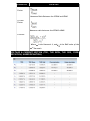
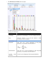
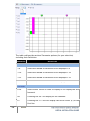
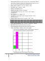
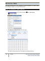
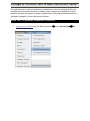
Averaging
In accordance to the IEC-61000-4-30 measurement standards, the G4K BLACKBOX
displays the following Average Measurements: Aggregation of 150/180 cycles
(3seconds); 10 minutes & 2 hours based at a Frequency of 10 minutes. This
window also displays the Flagging based on PQ configurations.
OPEN THE AVERAGE WINDOW
Access your G4K Unit via the Web Interface
select Monitoring
Average:
72
ELSPEC
G4K Fixed Power Quality Analyzer
USER & INSTALLATION GUIDE
73
The Average Window will now open:
ELSPEC
G4K Fixed Power Quality Analyzer
USER & INSTALLATION GUIDE
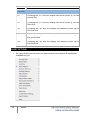
The table outlines the sections' Parameters including Definition:
PARAMETER
DEFINITION
Frequency
Frequency – 10 seconds averaging
Average
150/180 Cycles
Average Measurements at an aggregation of 150/180 cycles
(~3seconds)
Average 10 Min.
Average Measurements at an aggregation of 10 minutes
Average 2 Hours
Average Measurements at an aggregation of 2 hours
Under Deviation
150/180 Cycles
Displays how much lower the Average RMS Voltage is than the
Reference Voltage at an aggregation of 150/180 cycles
(~3seconds)
Under Deviation
10 Min.
Displays how much lower the Average RMS Voltage is than the
Reference Voltage at an aggregation of 10 minutes
Under Deviation
2 Hours
Displays how much lower the Average RMS Voltage is than the
Reference Voltage at an aggregation of 2 hours
Over Deviation
150/180 Cycles
Displays how much higher the Average RMS Voltage is than the
Reference Voltage at an aggregation of 150/180 cycles
(~3seconds)
Over Deviation
10 Min.
Displays how much higher the Average RMS Voltage is than the
Reference Voltage at an aggregation of 10 minutes
Over Deviation
2 Hours
Displays how much higher the Average RMS Voltage is than the
Reference Voltage at an aggregation of 2 hours
Unbalance
150/180 Cycles
The Supply Voltage Unbalance is Evaluated Using the Method
of Symmetrical Components in Accordance with IEC61000-4-30
This entry displays the Average Maximum/Minimum
Unbalanced Values at an aggregation of 150/180 cycles
(~3seconds)
74
Unbalance
Min.
10
This entry displays the Average Maximum/Minimum
Unbalanced Values at an aggregation of 10 minutes
Unbalance
Hours
2
This entry displays the Average Maximum/Minimum
Unbalanced Values at an aggregation of 2 hours
ELSPEC
G4K Fixed Power Quality Analyzer
USER & INSTALLATION GUIDE
SEE ALSO
75
Monitoring Real-Time Data
Voltage & Current Measurements
Power
Temperature
Phasors
Waveforms
Voltage Flickering
Pinst Waveform
Minimum / Maximum Flickering
Voltage & Current Harmonics
P & Q Harmonics
Spectrum
Harmonics Table
Voltage & Current, Min & Max Harmonics Table
PQ Min & Maximum Harmonics
ELSPEC
G4K Fixed Power Quality Analyzer
USER & INSTALLATION GUIDE
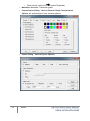
Power
This page displays different electrical power parameters relevant to the Specific
G4K Unit Configuration.
OPEN THE POWER SUMMARY WINDOW
Access your G4K Unit via the Web Interface
The Power Summary Window will now open:
select Monitoring
Power:
Verify your Configurations in this window that displays:
Active Power
Reactive Power
Apparent Power
True & Displacement Power Factor
In most network configurations the Active Power will reflect a Positive
Value. Should it have a Negative Value, recheck your Voltage & Current
Polarity Configuration. In the presence of a generator, the Active Power
will reflect a Negative Value.
The table outlines the sections' Parameters including Definition:
PARAMETER
Active
Power
DEFINITION
The amount of Active Power consumed as usable energy.
Sometimes referred to as Real Power. The portion of power
flow that, averaged over a complete cycle of the AC
waveform, results in the net transfer of energy in one
direction expressed as kWh.
In most network configurations the Active Power will reflect
a Positive Value. Should it have a Negative Value, recheck
your Voltage & Current Polarity Configuration. In the
presence of a generator, the Active Power will reflect a
Negative Value.
Elspec calculates the Active Power accurately by taking all
Harmonics up to the 40th into account using the following
formula:
i = Harmonic
j = Phase
Reactive
Power
The amount of Reactive Power consumed as unusable energy.
Energy that flows back and forth with no actual power flow.
Reactive Power flow transfers no net energy to the load and
is sometimes referred to as Wattless power. Elspec calculates
reactive power using the following formula:
Elspec calculates the sign of Q using the following formula:
Sign of Q = sign of:
Apparent
Power
The amount of Apparent Power; a vector addition of the
Active and Reactive Power. The combination of active and
reactive energy (kVAh)
Elspec uses formula:
77
ELSPEC
G4K Fixed Power Quality Analyzer
USER & INSTALLATION GUIDE
PARAMETER
True Power
Factor (PF)
DEFINITION
The ratio between Real Power & Apparent Power (a value
between 0 and 1). The most accurate measure of efficiency is
the True Power Factor. It is defined as the sum of the P/S
ratio over all the Harmonics:
QUADRAT
Displacement
Power Factor
(PF)
PF UNIT
I
+
+
+
IND
II
-
+
-
CAP
III
-
-
+
IND
IV
+
-
-
CAP
Same as True PF, But Only With Fundamental Components:
SEE ALSO
78
Monitoring Real-Time Data
Voltage & Current Measurements
Average
Temperature
Phasors
Waveforms
Voltage Flickering
Pinst Waveform
Minimum / Maximum Flickering
Voltage & Current Harmonics
P & Q Harmonics
Spectrum
ELSPEC
G4K Fixed Power Quality Analyzer
USER & INSTALLATION GUIDE
79
Harmonics Table
Voltage & Current, Min & Max Harmonics Table
PQ Min & Maximum Harmonics
ELSPEC
G4K Fixed Power Quality Analyzer
USER & INSTALLATION GUIDE
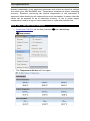
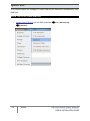
Temperature
Ambient temperature is an important parameter both within an electrical cabinet
and within your G4K BLACKBOX Unit. Temperature extremes do affect measuring
accuracy. Therefore, monitoring the internal temperature of the instrument is
important when monitoring all measured electrical parameters to ensure that the
values can be assumed to be of maximum accuracy. A rise in power supply
temperature could be a sign of loose connections or some other malfunction.
OPEN THE TEMPERATURE WINDOW
Access your G4K Unit via the Web Interface
Temperature:
The Temperature Window will now open:
select Monitoring
The table outlines the sections' Parameters including Definition:
PARAMETER
DEFINITION
Internal
Temperature
The average, minimum, and maximum internal
temperature of the DSP Module
External
Temperature
Utilizing a PT100 Thermometer, average, minimum,
and maximum outside temperatures are monitored.
The temperatures measured every network cycle and
averaged over 10 cycles. The data is stored in the
PQZIP files every 10 minutes.
PSU Temperature
The average minimum and maximum temperature of
the Power Supply Module
Reset all Min/Max measurements of your G4K Unit
SEE ALSO
Monitoring Real-Time Data
Voltage & Current Measurements
Average
Power
Phasors
Waveforms
Voltage Flickering
Pinst Waveform
Minimum / Maximum Flickering
Voltage & Current Harmonics
P & Q Harmonics
Spectrum
Harmonics Table
Voltage & Current, Min & Max Harmonics Table
PQ Min & Maximum Harmonics
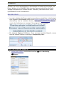
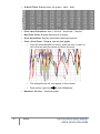
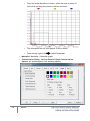
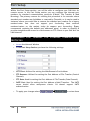
Phasors
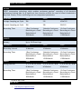
A Phasor is a vector representation of the Voltages & Currents in the system. The
Phasor Window of the BLACKBOX Web Interface represents both Wye and Delta
Voltage Configurations in a Phasor format. Therefore, the Phasors are a vector
representation of the First Harmonic.
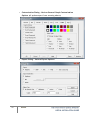
NOTE NOTE NOTE
In order to display the Phasor graph, ensure that you install the ActiveX plug-in
from Gigasoft (downloadable either from Elspec's Website's Support Section or
alternatively can be installed directly from your BLACKBOX CD). You will
receive the following error message if the program is not installed:
For Internet Explorer 8/9 Users: Once you have installed Gigasoft, ensure
that the Internet Explorer is running in Compatibility View:
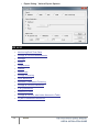
OPEN THE PHASORS WINDOW
Access your G4K Unit via the Web Interface
Phasors:
select Monitoring
The Phasor Window will now open:
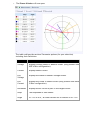
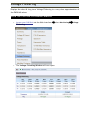
The table outlines the sections' Parameter options (for your selection)
including their Definition:
PARAMETER
DEFINITION
Voltage
Displays Voltage Phase to Neutral Phasor (only present with
WYE 4 Wire configuration)
Current
Displays Phase Current
Diff
Voltage
Displays the Phase to Neutral Voltages Phasor
Diff
Current
Displays the Phase to Phase Current (only present with Delta
3 Wire configuration)
Normalize
Displays the all vector as part of the largest vector
Ampl
The Amplitude of each Phasor
Angle
V1 /V12 is at 00, all other vectors are in relation to V1 /V12
CHART OPTIONS
84
Right-click on the chart to access various options & capabilities for the
chart:
You may use the following chart options & capabilities:
Viewing Style: Different styling options Color / Monochrome (B&W)
with/without Symbols / Bitmap etc. By selecting the option you can
view on screen the different styles available to you
Border Style: No Border, Thin Line, Shadow / Inset
Font Size: Large / Medium / Small
Show Legend: Display / Not display Legend
Plotting Method: From Line / Point / Point & Line
Data Shadows: Off / Shadow / 3D
Include Data Labels: Include / Exclude Numeric Data Labels
Mark Data Points: Mark/Unmark Data Points
Grid Options: Extend Radius Tick Marks, Both Degrees & Radius,
Degrees, Radius, Hid Grid Lines, Thin Grid Lines, Thick Grid Lines,
Dotted Grid Lines, Dashed Grid Lines & One Pixel Grid Lines
Maximize: Min / Max the Phasor Graph Only
ELSPEC
G4K Fixed Power Quality Analyzer
USER & INSTALLATION GUIDE
85
Customization Dialog - Various General Graph Customization
Options (all options):
Export Dialog - Various Export Options:
ELSPEC
G4K Fixed Power Quality Analyzer
USER & INSTALLATION GUIDE
SEE ALSO
Monitoring Real-Time Data
Voltage & Current Measurements
Average
Power
Temperature
Waveforms
Voltage Flickering
Pinst Waveform
Minimum / Maximum Flickering
Voltage & Current Harmonics
P & Q Harmonics
Spectrum
Harmonics Table
Voltage & Current, Min & Max Harmonics Table
PQ Min & Maximum Harmonics
Waveforms
The Waveform page displays the actual Voltage & Current waveforms monitored by
your G4K BLACKBOX Unit.
NOTE NOTE NOTE
In order to display the Phasor graph, ensure that you install the ActiveX plug-in
from Gigasoft (downloadable either from Elspec's Website's Support Section or
alternatively can be installed directly from your BLACKBOX CD). You will
receive the following error message if the program is not installed:
For Internet Explorer 8/9 Users: Once you have installed Gigasoft, ensure
that the Internet Explorer is running in Compatibility View:
OPEN THE WAVEFORMS WINDOW
Access your G4K Unit via the Web Interface
Waveforms:
select Monitoring
The Waveforms Window will now open:
The table outlines the sections' Parameter options (for your selection)
including their Definition:
PARAMETER
DEFINITION
Cycle
Cycle Selection (1-4 Cycles)
All
Checking the "All graphs" box will automatically select all
the boxes below
Voltage
Current
&
Depending on your power configuration, you can view all
combinations of phase to phase and phase to line voltage
and current combinations by making selections in the
appropriate check boxes
CHART OPTIONS
89
By right-clicking on the chart you have various chart options & capabilities
available to you:
Viewing Style: Different styling options Color / Monochrome (B&W)
with/without Symbols / Bitmap etc. By selecting the option you can
view on screen the different styles available to you
Border Style: No Border, Thin Line, Shadow / Inset
Font Size: Large / Medium / Small
Display / Not display Legend
Numeric Precision: No up to 3 Decimals
Plotting Method: From Line / Bar / Point / Area / Spline /
Combinations
Data Shadows: Off / Shadow / 3D
Grid Options: Various grid options ranging from dots / lines /
different axis etc.
ELSPEC
G4K Fixed Power Quality Analyzer
USER & INSTALLATION GUIDE
Graph & Table: Display either the graph / table / both:
Point Label Orientation: Auto / Vertical / Horizontal / Slanted
Mark Data Points: Displays data points on graph
Show Annotations: Displays annotations data descriptions
Zoom / Undo Zoom - Zoom in /out on your graph:
90
From the main Waveform window, select an area to zoom in.
Left-click and drag the mouse to define the area:
The enlarged area will now appear in the window
Zoom out by right/click
& select Zoom out
Maximize: Maximize / Minimize graph
ELSPEC
G4K Fixed Power Quality Analyzer
USER & INSTALLATION GUIDE
91
Customization Dialog - Various General Graph Customization
Options (all options apart from zooming above):
Export Dialog - Various Export Options:
ELSPEC
G4K Fixed Power Quality Analyzer
USER & INSTALLATION GUIDE
SEE ALSO
Monitoring Real-Time Data
Voltage & Current Measurements
Average
Power
Temperature
Phasors
Voltage Flickering
Pinst Waveform
Minimum / Maximum Flickering
Voltage & Current Harmonics
P & Q Harmonics
Spectrum
Harmonics Table
Voltage & Current, Min & Max Harmonics Table
PQ Min & Maximum Harmonics
Voltage Flickering
Displays the short & long term Voltage Flickering to a very close approximation of
the EN50160 values.
OPEN THE VOLTAGE FLICKERING WINDOW
select Monitoring
Access your G4K Unit via the Web Interface
Flickering:
The Voltage Flickering Window will now open:
Voltage
The table outlines the sections' Parameter options (for your selection)
including their Definition:
PARAMETER
DEFINITION
PST INST
Instantaneous flicker evaluation.
Output of Block 5 of the
Flickermeter in Accordance with IEC61000-4-15 Edition 2
PSST 10
Sec.
An Elspec measurement designed to get quicker results regarding
Flicker evaluation. This measurement reaches a very close
approximation of the EN50160 values, but in a fraction of the time.
The PSST is calculated the same as PST but averaged over 10
seconds. This Elspec defined value is valuable in that it enables
faster assessment of the flicker. Elspec PSST converges to a real
value within 3 min from a drastic flicker change, or immediately for
periodic steady state flicker
PST
Where the Percentiles
,
,
,
,
are the Flicker Levels
Exceeded for 0.1, 1, 3, 10 & 50% of the Time During The Observation
Period. The Suffix “s” in the Formula Indicates that the Smoothed
Value Should be Used. The Smoothed Values are Obtained Using the
Following Formulas:
P(1s) = (P(.7) + P(1) + P(1.5))/3
P(3s) = (P(2.2) + P(3) + P(4))/3
P(10s) = (P(6) + P(8) + P(10) + P(13) + P(17))/5
P(50s) = (P(30) + P(50) + P(80))/3
PST 10
Min
Short term flicker evaluation.
P ST is a value measured over 10 minutes that characterizes the
likelihood that the voltage fluctuations would result in perceptible
light flicker. A value of 1.0 is designed to represent that 50% of
people would perceive flicker in a 60 watt incandescent bulb.
PLT
94
ELSPEC
G4K Fixed Power Quality Analyzer
USER & INSTALLATION GUIDE
PARAMETER
DEFINITION
SPLT 1 Hour
An Elspec measurement designed to get quicker results regarding
Flicker evaluation. This measurement reaches a very close
approximation of the EN50160 values, but in a fraction of the
time.
The SPLT is calculated the same as PLT but averaged over 1 hour.
This Elspec defined value is valuable in that it enables faster
assessment of the flicker
PLT 2 Hour
The Long-Term PLT is Derived From the Short-Term Values Over 12
Short-Term Values of 10 Minutes Each Over a Period of 2 hours
LPLT 10
Hour
An Elspec measurement designed to give better results regarding
Flicker evaluation by using a longer averaging time. The LP LT is
calculated the same as P LT but averaged over 10 hours to allow a
quicker "long term" average
LPLT 7 Day
An Elspec measurement designed to give better results regarding
Flicker evaluation by using a longer averaging time.
The LP LT is calculated the same as P LT but averaged over 7 days, as
per EN50160 parts 4-15
Reset all Flickering measurements of your G4K Unit
SEE ALSO
Monitoring Real-Time Data
Voltage & Current Measurements
Average
Power
Temperature
Phasors
Waveforms
Pinst Waveform
Minimum / Maximum Flickering
Voltage & Current Harmonics
P & Q Harmonics
Spectrum
Harmonics Table
Voltage & Current, Min & Max Harmonics Table
PQ Min & Maximum Harmonics
Pinst Waveform
Pinst is instantaneous flicker sensation that the G4K calculates for every selected
channel.
OPEN THE PINST WAVEFORM WINDOW
96
Access your G4K Unit via the Web Interface
Waveforms:
The Pinst Waveforms Window will now open:
ELSPEC
select Monitoring
Pinst
G4K Fixed Power Quality Analyzer
USER & INSTALLATION GUIDE
The table outlines the sections' Parameter options (for your selection)
including their Definition:
PARAMETER
DEFINITION
All
Checking the "All graphs" box will automatically select all
the boxes below
Voltage
Channels
Select the applicable channel for Flickering Waveform
display.
SEE ALSO
97
Monitoring Real-Time Data
Voltage & Current Measurements
Average
Power
Temperature
Phasors
Waveforms
Voltage Flickering
Minimum / Maximum Flickering
Voltage & Current Harmonics
P & Q Harmonics
Spectrum
Harmonics Table
Voltage & Current, Min & Max Harmonics Table
PQ Min & Maximum Harmonics
ELSPEC
G4K Fixed Power Quality Analyzer
USER & INSTALLATION GUIDE
Minimum / Maximum Flickering
Displays the minimum & maximum short & long term Voltage Flickering vales to a
very close approximation of the EN50160 values.
OPEN THE MIN/MAX FLICKERING WINDOW
Access your G4K Unit via the Web Interface
select Monitoring
Min/Max Flickering:
98
The Min/Max Flickering Window will now open:
ELSPEC
G4K Fixed Power Quality Analyzer
USER & INSTALLATION GUIDE
The table outlines the sections' Parameter options (for your selection) including
their Definition:
PARAMETER
DEFINITION
PST INST
Instantaneous flicker evaluation.
Output of Block 5 of the
Flickermeter in Accordance with IEC61000-4-15 Edition 2
PSST 10 Sec.
An Elspec measurement designed to get quicker results regarding
Flicker evaluation. This measurement reaches a very close
approximation of the EN50160 values, but in a fraction of the time.
The PSST is calculated the same as PST but averaged over 10
seconds. This Elspec defined value is valuable in that it enables
faster assessment of the flicker. Elspec PSST converges to a real
value within 3 min from a drastic flicker change, or immediately for
periodic steady state flicker
PST
Where the Percentiles
,
,
,
,
are the Flicker Levels
Exceeded for 0.1, 1, 3, 10 & 50% of the Time During The Observation
Period. The Suffix “s” in the Formula Indicates that the Smoothed
Value Should be Used. The Smoothed Values are Obtained Using the
Following Formulas:
P(1s) = (P(.7) + P(1) + P(1.5))/3
P(3s) = (P(2.2) + P(3) + P(4))/3
P(10s) = (P(6) + P(8) + P(10) + P(13) + P(17))/5
P(50s) = (P(30) + P(50) + P(80))/3
PST 10 Min
Short term flicker evaluation.
P ST is a value measured over 10 minutes that characterizes the
likelihood that the voltage fluctuations would result in perceptible
light flicker. A value of 1.0 is designed to represent that 50% of
people would perceive flicker in a 60 watt incandescent bulb.
PLT
Where
(i = 1, 2, 3, ...) are Consecutive Readings of the Short-
Term Severity
99
ELSPEC
G4K Fixed Power Quality Analyzer
USER & INSTALLATION GUIDE
PARAMETER
SPLT 1 Hour
DEFINITION
An Elspec measurement designed to get quicker results regarding
Flicker evaluation. This measurement reaches a very close
approximation of the EN50160 values, but in a fraction of the time.
The SPLT is calculated the same as PLT but averaged over 1 hour.
This Elspec defined value is valuable in that it enables faster
assessment of the flicker
PLT 2 Hour
The Long-Term PLT is Derived From the Short-Term Values Over 12
Short-Term Values of 10 Minutes Each Over a Period of 2 hours
LPLT 10 Hour
An Elspec measurement designed to give better results regarding
Flicker evaluation by using a longer averaging time. The LP LT is
calculated the same as P LT but averaged over 10 hours to allow a
quicker "long term" average
LPLT 1 Day
An Elspec measurement designed to give better results regarding
Flicker evaluation by using a longer averaging time.
The LP LT is calculated the same as P LT but averaged over 1 day
LPLT 7 Day
An Elspec measurement designed to give better results regarding
Flicker evaluation by using a longer averaging time.
The LP LT is calculated the same as P LT but averaged over 7 days, as per
EN50160 parts 4-15
Reset all Flickering measurements of your G4K Unit
SEE ALSO
Monitoring Real-Time Data
Voltage & Current Harmonics
Voltage & Current Measurements
P & Q Harmonics
Average
Spectrum
Power
Harmonics Table
Temperature
Phasors
Voltage & Current, Min & Max
Harmonics Table
Waveforms
PQ Min & Maximum Harmonics
Voltage Flickering
Pinst Waveform
Minimum / Maximum Flickering
100
ELSPEC
G4K Fixed Power Quality Analyzer
USER & INSTALLATION GUIDE
Voltage & Current Harmonics
This window opens the Spectrum of Voltage & Current Harmonics measured by your
G4K Unit. The graph is able to display of up to 40 Harmonics.
OPEN THE V&I HARMONICS WINDOW
101
Access your G4K Unit via the Web Interface
Harmonics:
ELSPEC
select Monitoring
V&I
G4K Fixed Power Quality Analyzer
USER & INSTALLATION GUIDE
The V&I Harmonics Window will now open:
The table outlines the sections' Parameter options (for your selection)
including their Definition:
PARAMETER
DEFINITION
Timestamp
Indicates the timestamps of the last averaging intervals
Flag
Indicates whether or not the last interval is valid
according to the set standard
MEASUREMENT TYPE
Harmonics
Real time (10/12 cycles) calculation of sub group
harmonics, in accordance with IEC61000-4-7.
Interharmonics
Real time (10/12 cycles) calculation of inter sub group
harmonics, in accordance with IEC61000-4-7.
150/180
Harmonic
150/180 Cycle averaging of the sub group harmonics
Cycles
PARAMETER
DEFINITION
150/180 Cycles
Interharmonic
150/180 Cycle averaging of the inter sub group harmonics
10 Min Harmonic
10 Minutes averaging of the sub group harmonics
10 Min
Interharmonic
10 Minutes averaging of the inter sub group harmonics
2 Hour Harmonic
2 Hours averaging of the 10 minutes averaging of the sub
group harmonics
2 Hour
Interharmonic
2 Hours averaging of the 10 minutes averaging of the
inter sub group harmonics
Harmonic's Angle
The angle of each harmonic based on the real time value
RANGE
1-8
Select the number of harmonics to be displayed 1-8
1-16
Select the number of harmonics to be displayed 1-16
1-32
Select the number of harmonics to be displayed 1-32
1-50
Select the number of harmonics to be displayed 1-50
OPTIONS
First
Check/Uncheck the checkbox in order to display/not
display the first harmonic
Relative
Check/Uncheck the checkbox in order to display/not
display the harmonics relative to the first harmonic
(Whereas the first harmonic is 100, and the other
harmonic values as part of the harmonic 100)
All
Checking the "All" will display all the channels
Voltage & Current
Select the applicable Voltage / Current channel to be
displayed
CHART OPTIONS
By right-clicking on the chart you have various chart options & capabilities
available to you:
Viewing Style: Different styling options Color / Monochrome (B&W)
with/without Symbols / Bitmap etc. By selecting the option you can
view on screen the different styles available to you
Border Style: No Border, Thin Line, Shadow / Inset
Font Size: Large / Medium / Small
Display / Not display Legend
Numeric Precision: No up to 3 Decimals
Plotting Method: From Line / Bar / Point / Area / Spline /
Combinations
Data Shadows: Off / Shadow / 3D
Grid Options: Various grid options ranging from dots / lines /
different axis etc.
Graph & Table: Display either the graph / table / both:
Point Label Orientation: Auto / Vertical / Horizontal / Slanted
Mark Data Points: Displays data points on graph
Show Annotations: Displays annotations data descriptions
105
Zoom / Undo Zoom - Zoom in /out on your graph:
From the main Waveform window, select an area to zoom in.
Left-click and drag the mouse to define the area:
The enlarged area will now appear in the window
Zoom out by right/click
& select Zoom out
Maximize: Maximize / Minimize graph
Customization Dialog - Various General Graph Customization
Options (all options apart from zooming above):
ELSPEC
G4K Fixed Power Quality Analyzer
USER & INSTALLATION GUIDE
Export Dialog - Various Export Options:
SEE ALSO
Monitoring Real-Time Data
Voltage & Current Measurements
Average
Power
Temperature
Phasors
Waveforms
Voltage Flickering
Pinst Waveform
Minimum / Maximum Flickering
P & Q Harmonics
Spectrum
Harmonics Table
Voltage & Current, Min & Max Harmonics Table
PQ Min & Maximum Harmonics
106
ELSPEC
G4K Fixed Power Quality Analyzer
USER & INSTALLATION GUIDE
P & Q Harmonics
This window opens the Active & Reactive Harmonic Powers measured by your G4K
Unit.
OPEN THE P&Q HARMONICS WINDOW
Access your G4K Unit via the Web Interface
Harmonics:
The P&Q Harmonics Window will now open:
107
ELSPEC
select Monitoring
P&Q
G4K Fixed Power Quality Analyzer
USER & INSTALLATION GUIDE
The table outlines the sections' Parameter options (for your selection)
including their Definition:
PARAMETER
DEFINITION
RANGE
1-8
Select the number of harmonics to be displayed 1-8
1-16
Select the number of harmonics to be displayed 1-16
1-32
Select the number of harmonics to be displayed 1-32
1-50
Select the number of harmonics to be displayed 1-50
OPTIONS
108
First
Select either Yes/No in order to display or not display the first
harmonic
All
Checking the "All" will display all the channels
P1
Checking the "P1" box will display the Active Power (P) of the
first line
ELSPEC
G4K Fixed Power Quality Analyzer
USER & INSTALLATION GUIDE
PARAMETER
DEFINITION
OPTIONS
P2
Checking the "P2" box will display the Active Power (P) of the
second line
P3
Checking the "P3" box will display the Active Power (P) of the
third line
Q1
Checking the "Q1" box will display the Reactive Power (Q) of
the first line
Q2
Checking the "Q2" box will display the Reactive Power (Q) of
the second line
Q3
Checking the "Q3" box will display the Reactive Power (Q) of
the third line
CHART OPTIONS
109
By right-clicking on the chart you have various chart options & capabilities
available to you:
ELSPEC
G4K Fixed Power Quality Analyzer
USER & INSTALLATION GUIDE
110
Viewing Style: Different styling options Color / Monochrome (B&W)
with/without Symbols / Bitmap etc. By selecting the option you can
view on screen the different styles available to you
Border Style: No Border, Thin Line, Shadow / Inset
Font Size: Large / Medium / Small
Display / Not display Legend
Numeric Precision: No up to 3 Decimals
Plotting Method: From Line / Bar / Point / Area / Spline /
Combinations
Data Shadows: Off / Shadow / 3D
Grid Options: Various grid options ranging from dots / lines /
different axis etc.
Graph & Table: Display either the graph / table / both:
Point Label Orientation: Auto / Vertical / Horizontal / Slanted
Mark Data Points: Displays data points on graph
Show Annotations: Displays annotations data descriptions
Zoom / Undo Zoom - Zoom in /out on your graph:
From the main Waveform window, select an area to zoom in.
Left-click and drag the mouse to define the area:
The enlarged area will now appear in the window
ELSPEC
G4K Fixed Power Quality Analyzer
USER & INSTALLATION GUIDE
111
Zoom out by right/click
& select Zoom out
Maximize: Maximize / Minimize graph
Customization Dialog - Various General Graph Customization
Options (all options apart from zooming above):
Export Dialog - Various Export Options:
ELSPEC
G4K Fixed Power Quality Analyzer
USER & INSTALLATION GUIDE
SEE ALSO
Monitoring Real-Time Data
Voltage & Current Measurements
Average
Power
Temperature
Phasors
Waveforms
Voltage Flickering
Pinst Waveform
Minimum / Maximum Flickering
Voltage & Current Harmonics
Spectrum
Harmonics Table
Voltage & Current, Min & Max Harmonics Table
PQ Min & Maximum Harmonics
Spectrum
This window opens the Voltage & Current Sub & Inter-Harmonics measured by your
G4K Unit.
OPEN THE SPECTRUM WINDOW
Access your G4K Unit via the Web Interface
select Monitoring
Spectrum:
113
ELSPEC
G4K Fixed Power Quality Analyzer
USER & INSTALLATION GUIDE
The Spectrum Window will now open:
The table outlines the sections' Parameter options (for your selection)
including their Definition:
PARAMETER
DEFINITION
DC
Check/Uncheck the checkbox in order to display/not display
the DC Harmonics
First
Check/Uncheck the checkbox in order to display/not display
the First Harmonic
Relative
Check/Uncheck the checkbox in order to display/not display
the harmonics relative to the first harmonic (Whereas the
first harmonic is 100, and the other harmonic values as part
of the harmonic 100)
All
Checking the "All" will display all the channels
Voltage &
Current
Select the applicable Voltage / Current channel to be
displayed
CHART OPTIONS
By right-clicking on the chart you have various chart options & capabilities
available to you:
Viewing Style: Different styling options Color / Monochrome (B&W)
with/without Symbols / Bitmap etc. By selecting the option you can
view on screen the different styles available to you
Border Style: No Border, Thin Line, Shadow / Inset
Font Size: Large / Medium / Small
Display / Not display Legend
Numeric Precision: No up to 3 Decimals
Plotting Method: From Line / Bar / Point / Area / Spline /
Combinations
Data Shadows: Off / Shadow / 3D
Grid Options: Various grid options ranging from dots / lines /
different axis etc.
Graph & Table: Display either the graph / table / both:
Point Label Orientation: Auto / Vertical / Horizontal / Slanted
Mark Data Points: Displays data points on graph
Show Annotations: Displays annotations data descriptions
Zoom / Undo Zoom - Zoom in /out on your graph:
116
From the main Waveform window, select an area to zoom in.
Left-click and drag the mouse to define the area:
The enlarged area will now appear in the window
Zoom out by right/click
& select Zoom out
Maximize: Maximize / Minimize graph
Customization Dialog - Various General Graph Customization
Options (all options apart from zooming above):
ELSPEC
G4K Fixed Power Quality Analyzer
USER & INSTALLATION GUIDE
Export Dialog - Various Export Options:
SEE ALSO
Monitoring Real-Time Data
Voltage & Current Measurements
Average
Power
Temperature
Phasors
Waveforms
Voltage Flickering
Pinst Waveform
Minimum / Maximum Flickering
Voltage & Current Harmonics
P & Q Harmonics
Harmonics Table
Voltage & Current, Min & Max Harmonics Table
PQ Min & Maximum Harmonics
117
ELSPEC
G4K Fixed Power Quality Analyzer
USER & INSTALLATION GUIDE
Harmonics Table
This page summarizes all the Voltage & Current Harmonics in either Value Percentages or Angles - up to the 50th Harmonic.
OPEN THE HARMONICS TABLE WINDOW
Access your G4K Unit via the Web Interface
select Monitoring
Harmonics Table:
The Harmonics Table Window will now open:
The table outlines the sections' Parameters including Definition:
118
ELSPEC
G4K Fixed Power Quality Analyzer
USER & INSTALLATION GUIDE
PARAMETER
DEFINITION
Timestamp
Indicates the timestamps of the last averaging intervals
Flag
Indicates whether or not the last interval is valid
according to the set standard
MEASUREMENT TYPE
Harmonics
Real time (10/12 cycles) calculation of sub group
harmonics, in accordance with IEC61000-4-7:
Interharmonics
Real time (10/12 cycles) calculation of inter sub group
harmonics, in accordance with IEC61000-4-7
150/180 Cycles
Harmonic
150/180 Cycle averaging of the sub group harmonics
MEASUREMENT TYPE
119
150/180 Cycles
Interharmonic
150/180 Cycle averaging of the inter sub group harmonics
10 Min Harmonic
10 Minutes averaging of the sub group harmonics
10 Min
Interharmonic
10 Minutes averaging of the inter sub group harmonics
2 Hour Harmonic
2 Hours averaging of the 10 minutes averaging of the sub
group harmonics
2 Hour
Interharmonic
2 Hours averaging of the 10 minutes averaging of the inter
sub group harmonics
Harmonic's
Angle
The angle of each harmonic based on the real time value
ELSPEC
G4K Fixed Power Quality Analyzer
USER & INSTALLATION GUIDE
PARAMETER
DEFINITION
RANGE
1-128
Select the number of harmonics to be displayed 1-128
129-256
Select the number of harmonics to be displayed 129-256
257-384
Select the number of harmonics to be displayed 257-384
1-50
Select the number of harmonics to be displayed 285-511
OPTIONS
First
Check/Uncheck the checkbox in order to display/not display the
First Harmonic
Relative
Check/Uncheck the checkbox in order to display/not display the
harmonics relative to the first harmonic (Whereas the first
harmonic is 100, and the other harmonic values as part of the
harmonic 100)
All
Checking the "All" will display all the channels
Voltage
Current
&
Select the applicable Voltage / Current channel to be displayed
SEE ALSO
Monitoring Real-Time Data
Voltage & Current Measurements
Average
Power
Temperature
Phasors
Waveforms
Voltage Flickering
Pinst Waveform
Minimum / Maximum Flickering
Voltage & Current Harmonics
P & Q Harmonics
Spectrum
Voltage & Current, Min & Max Harmonics Table
PQ Min & Maximum Harmonics
Voltage & Current, Min & Max Harmonics Table
For each Harmonic, there is a Minimum & Maximum value for Voltage & Current.
Voltage values are seen as phase to phase, while currents are displayed in both
phase to neutral and phase to phase combinations. This page summarizes all the
minimum Voltage & Current Harmonics Values.
OPEN THE V/I MIN/MAX HARMONICS WINDOW
Access your G4K Unit via the Web Interface
Min/Max Harmonics:
select Monitoring
V/I
The window containing the table for V/I Min/Max Harmonics values will now
open:
The table outlines the sections' Parameters including Definition:
PARAMETER
DEFINITION
Harmonics Angle
Check in order to display the Min/Max value of the
Harmonics Angle
Harmonics Value
Check in order to display the Min/Max value of the
Harmonics Value (amplitude)
Reset all Min/Max measurements of your G4K Unit
SEE ALSO
Monitoring Real-Time Data
Voltage & Current Measurements
Average
Power
Temperature
Phasors
Waveforms
Voltage Flickering
Pinst Waveform
Minimum / Maximum Flickering
Voltage & Current Harmonics
P & Q Harmonics
Spectrum
Harmonics Table
PQ Min & Maximum Harmonics
123
ELSPEC
G4K Fixed Power Quality Analyzer
USER & INSTALLATION GUIDE
PQ Min & Maximum Harmonics
This page summarizes all the minimum & maximum Active & Reactive Power
Harmonic Values per phase, up to the 50th Harmonic.
(P) = Active Power Harmonic Values
(Q) = Reactive Power Harmonic Values
OPEN THE P/Q MIN/MAX HARMONICS WINDOW
124
Access your G4K Unit via the Web Interface
Min/Max Harmonics:
ELSPEC
select Monitoring
P/Q
G4K Fixed Power Quality Analyzer
USER & INSTALLATION GUIDE
The window containing the table for P/Q Min/Max Harmonics values will
now open:
The table outlines the sections' Parameters including Definition:
PARAMETER
DEFINITION
P1
Displays the Active Power (P) of the first line
P2
Displays the Active Power (P) of the second line
P3
Displays the Active Power (P) of the third line
Q1
Displays the Reactive Power (Q) of the first line
Q2
Displays the Reactive Power (Q) of the second line
Q3
Displays the Reactive Power (Q) of the third line
Reset all Min/Max measurements of your G4K Unit
SEE ALSO
Monitoring Real-Time Data
Voltage & Current Measurements
Average
Power
Temperature
Phasors
Waveforms
Voltage Flickering
Pinst Waveform
Minimum / Maximum Flickering
Voltage & Current Harmonics
P & Q Harmonics
Spectrum
Harmonics Table
Voltage & Current, Min & Max Harmonics Table
About Power Quality Monitoring
The BLACKBOX contains a power quality compliance engine that enables real-time
evaluation of power quality according to standards such as EN50160. Power Quality
(PQ) Compliance is a set of electrically measured parameters which are typically
calculated based on some pre-defined intervals or event triggers and are evaluated
over a large observation window. For most of the PQ parameters, the observation
window is one week, which means the displayed online information refers to the
previous week. However, using ELSPEC's PQSCADA and Investigator applications, all
time intervals are able to be observed.
A PQ parameter is typically based on a power quality event. For example, the DIP
PQ parameter is based on counting DIP events over some observation period.
Different national standards vary the way a specific PQ parameter is being
measured or observed. The PQ Engine also supports a mode that can be customized
by the user, in which all compliance parameters can be self-edited and modified in
order to meet new conditions, rules, measuring intervals, and even different
observation periods.
The Power Quality section in Elspec's Web Interface is used to control and view
power quality measurement and compliance information computed by the PQ
Engine that includes:
View & Evaluate Summary of the Compliance Engine
View Detailed Compliance Information
View Graphical Bars of Compliance Levels
Set & View Log of Events
127
ELSPEC
G4K Fixed Power Quality Analyzer
USER & INSTALLATION GUIDE
PQ Compliance Summary
In this window you are able to review the specific Compliance Standard & Status
that is being evaluated by your G4K Unit's Internal Compliance Engine.
OPEN THE COMPLIANCE SUMMARY WINDOW
Access your G4K Unit
Power Quality
128
log on as the Viewer/Administrator
under
open the Summary Tab:
The Summary window will now open:
ELSPEC
G4K Fixed Power Quality Analyzer
USER & INSTALLATION GUIDE
EVENT STATUS SECTION
The Events Status Table shows a high level PASS or FAIL indication of each PQ
parameter. Any PQ parameter that has an incomplete observation period will be
presented as N/A (Not Available).
The definitions defined below are PQ
Parameters Configured as per EN50160 compliance. You may choose any other PQ
Compliance or set your own Unique PQ Compliance:
Voltage Frequency OK/FAIL: Frequency compliance is based on statistics:
N, N1 & N2. Frequency measurement interval is 10 sec. in an entire
observation window of 1 week. N - amount of intervals. N1 - intervals
frequency exceeded [+1.00%,-1.00%] from Nominal Frequency. N2 - intervals
frequency exceeded [+4.00%,-6.00%] from Nominal Frequency. N1 & N2
increment only if valid voltage inside nominal boundary of [+15.0%,-15.0%].
Compliance if both N1/N <= 5% of time & N2=0 of time. Intervals with
voltage interruption are discarded. Intervals with DIPS or Over voltage are
discarded.
Supply Voltage Variations OK/FAIL: Variations are evaluated by collecting
statistics: N, N1 & N2. Statistics are collected as average voltage within
intervals of 10 min. in observation window of 1 week. N - amount of
intervals. N1 - intervals voltage exceeded [+10.0%,-10.0%] boundary of
nominal. N2 - intervals voltage exceeded [+15.0%,-15.0%] boundary of
nominal. Compliance if N1/N <=5% & N2=0 during the entire observation
window. Intervals with voltage interruption are discarded. Intervals with
DIPS or OVER Voltage are discarded.
Rapid Voltage Changes OK/FAIL: Rapid voltage change is based on a 3 sec.
window in which RMS voltage minimum & maximum values are obtained
(minimum/maximum values should be within +-10.0% from nominal). The
rapid change is the percent of delta between minimum & maximum divided
by average RMS of 9 sec. The Rapid percent results are evaluated during
observation window of 1 week. Rapid changes are limited to specific count
(N): Rapids of more 5.00% allowed: N <= 65536 occurrences.
Supply Voltage Dips OK/FAIL: DIP is a voltage drop of more than 10.0% from
Nominal (but no more than 100.0%, & deactivate on 8.0%) DIP minimum time
is 10 ms. & maximum time of 1 min. DIP events are counted per all phases
combined within observation window of 1 week. Total events (N) allowed is:
20.
Short Interruptions OK/FAIL: Short interruption is a voltage drop of less
than 97.0% from nominal (event deactivate on 77.6%). Min duration 10 ms.,
Max duration 3 min. events are counted in the entire observation window of
1 week. Total events (N) allowed is: 2.
Long Interruptions OK/FAIL: Long interruptions are the same as short ones
but with a longer duration (longer than short interruption maximum time).
129
ELSPEC
G4K Fixed Power Quality Analyzer
USER & INSTALLATION GUIDE
Long interruptions events are counted within observation window of 1 week.
Total events (N) allowed is: 1.
Temporary Overvoltage OK/FAIL: Over-voltage events are characterized
with RMS voltage higher than 10.0% above Nominal (event deactivate on
8.0%). Minimum over-voltage event duration is 10 ms., events are counted
per all phases combined within observation window of 1 week. No specific
events count limitation is defined.
Flicker Severity OK/FAIL: Flicker severity is evaluated within observation
window of 1 week. During interruption Flicker interval is discarded. During
DIPS or Over voltage Flicker Interval is discarded. Plt (2 hours) must be
equal or under 1.0 during 95.0% of observation time.
Harmonic Voltage OK/FAIL: Harmonics evaluated at intervals of 10 min.
within observation window of 1 week. Evaluation at intervals in which
voltage is inside nominal boundary of [+15.0%,-15.0%]. Discarding Intervals
with VOLT-INT. Discarding Intervals with DIPS or OVER-VOLT. Individual
Harmonics are limited according to the following table: H2<=2.0%,
H3<=5.0%, H4<=1.0%, H5<=6.0%, H6<=0.5%, H7<=5.0%, H8<=0.5%, H9<=1.5%,
H10<=0.5%, H11<=3.5%, H12<=0.5%, H13<=3.0%, ... THD limit is set 8.0%
(N2). THD and Harmonics limits shall be kept at least 95.0% of time.
Supply Voltage Unbalance OK/FAIL: Voltage unbalance is evaluated at
intervals of 10 min. within observation window of 1 week. Evaluation is only
at intervals in which voltage is inside nominal boundary of [+15.0%,-15.0%].
Unbalance limit N1 is set to 2.00% and must be kept 95.0% of observation
time. Intervals with voltage interruption are discarded. Intervals with DIPS
or Over voltage are discarded.
COMPLIANCE SUMMARY SECTION
The Compliance Type is configured when setting your Instrument in PQ
Compliance Configuration.
Running Status means whether or not the G4K’s Power Quality engine is
evaluating the power quality according to the Configured PQ Compliance.
The Embedded Report field further indicates a type of report that is autogenerated internally in the device's file system. Most compliance types do
not generate any specific report, & therefore, the report type will be None.
However, CREG type of compliance (used in Colombia) also auto-generates a
specific format of Report Files as defined by the local regulator.
The Evaluation Status field provides an overall status of PASS or FAIL of the
entire compliance. Anytime the evaluation period is not complete (typically
required is a 1 week observation), the status will be N/A (Not Available),
otherwise PASS will be indicated as OK.
130
ELSPEC
G4K Fixed Power Quality Analyzer
USER & INSTALLATION GUIDE
The Start Time field shows the last time the compliance engine was
restarted. The entire state & observation window history is stored on the
internal non-volatile memory, so even after powering down; the Engine will
continue its evaluation & maintain all indications. (Start time remains
unchanged after device powered up.)
The Window Time On/Off fields specify how much aggregated time is
already in the observation window. ON refers to the aggregated window
time the device was powered on & OFF refers to the amount of window
time the device power was off. The format presented is [Days: Hours:
Minutes: Seconds]. Ideally the OFF time is all zeroes & the ON time is 7 days
(which is the typical full observation period in most of the compliance
types). Once the observation window reaches 7 days, it will start to slide in
steps of 2 hours. Sliding means the information from the oldest 2 hours is
being dropped, where a new up-to-date 2-hour interval is being used for
calculations.
The Measurement Flag field indicates whether there is a power quality
event such as a DIP/SWELL or INTERRUPTION at the moment.
NOTE NOTE NOTE
All underlined parameters are accompanied by a Tool Tip, Right-click on the
command to open the Tool Tip & x to close the Pop-up:
SEE ALSO:
About Power Quality Monitoring
Compliance Information
Compliance Chart
Events
PQ Compliance Configuration
131
ELSPEC
G4K Fixed Power Quality Analyzer
USER & INSTALLATION GUIDE
Compliance Information
This window contains detailed compliance information.
ACCESS THE COMPLIANCE INFORMATION WINDOW
Access your G4K Unit
Summary
132
log on as the Viewer/Administrator
under
open the Information Tab:
The Information window will now open:
ELSPEC
G4K Fixed Power Quality Analyzer
USER & INSTALLATION GUIDE
COLUMN - DEFINITIONS
Status/Partial: Contains two status indicators. The upper indicator refers to
the entire observation window’s PASS/FAIL result (same status as presented
in the Summary page), while the lower indicator is a PASS/FAIL indicator of
the most recent period. This recent indicator serves as real-time indicator &
typically reflects to only minutes to a few hours of history (this is dependent
on the specific PQ parameter measurement' intervals & method).
Observation: Indicates whether the observation of a specific PQ parameter
is complete.
Window/Interval: Upper Area - Provides the observation window time
(contains historical data used for the calculations). You may uniquely set
the observation period in User Defined Pages (Options - 1 or 2 Hours, or 1
Day, or 1 Week, or 1 Year). Lower Area – Provides the measurement
interval time or parameter resolution that falls within the observation
window (the measured time length for the PQ parameter). The interval may
also be set in User Defined Pages (Options - 1, 3, 10 or 20 seconds, or 1, 3,
10 or 30 minutes, or 1, or 2 Hours, or 1 Day). If you configure your PQ
Compliance to a set standard (i.e. EN50160), the Observation Window &
Interval Time will be calculated according to the standard.
Time OK/Time FAIL: provides the percentage of time the PQ parameter
was OK (as green text on the upper area) & percentage of time the PQ
parameter was outside the defined limits or FAILED (as red text in the lower
area) for the entire observation period (Observation Window). Example as
per the Information Window: if Voltage Dips was observed for a period of 1
week at a resolution of 10 ms (interval), the PQ parameter was OK for
97.647% & FAILED for 2.352% of the time (observation week). It should not
be confused to the lower area on the previous column.
Time N/A: Provides the percentage of time the unit was not measuring due
to lack of power.
Total Events: Provides the overall number of PQ events influenced by the
PQ parameter in the observation window.
133
ELSPEC
G4K Fixed Power Quality Analyzer
USER & INSTALLATION GUIDE
NOTE NOTE NOTE
All underlined parameters are accompanied by a Tool Tip, Right-click on the
command to open the Tool Tip & x to close the Pop-up:
SEE ALSO:
About Power Quality Monitoring
PQ Compliance Summary
Compliance Chart
Events
PQ Compliance Configuration
Compliance Chart
This page displays graphical bars of compliance levels (equals to percentage of
time OK).
ACCESS THE COMPLIANCE CHART WINDOW
Access your G4K Unit
Power Quality
log on as the Viewer/Administrator
under
open the Chart Tab:
The Compliance Chart window will now open:
The minimum and maximum values in the chart may be configured by
deselecting Auto for each value (Default = 90% Min / 100% Max)
CHART OPTIONS
As the Compliance Chart is intended to be used only as a chart & regardless that
all the options are displayed, only certain options & capabilities are available for
the Compliance Chart.
Right-click on the chart to access the options:
You may use the following chart options & capabilities:
136
Viewing Style: Different styling options Color / Monochrome (B&W)
with/without Symbols / Bitmap etc. By selecting the option you can
view on screen the different styles available to you
Border Style: No Border, Thin Line, Shadow / Inset
Font Size: Large / Medium / Small
Data Shadows: Off / Shadow / 3D
Dialog - Various Export Options:
ELSPEC
G4K Fixed Power Quality Analyzer
USER & INSTALLATION GUIDE
SEE ALSO:
About Power Quality Monitoring
PQ Compliance Summary
Compliance Information
Events
PQ Compliance Configuration
137
ELSPEC
G4K Fixed Power Quality Analyzer
USER & INSTALLATION GUIDE
Events
The Events window supplies a Log that displays Configured PQ Events. Within in
the Log you can decide what data you would like to display & produce a report.
OPEN THE EVENTS WINDOW TO PRODUCE A PQ EVENT LOG
Access your G4K Unit
Power Quality
log on as the Viewer/Administrator
under
open the Event Tab:
The Event Log window will now open:
Options & Functions:
Start at: Specify the event range
Page Size: Number of entries per page
Time: Log entries will be displayed at specific time zone (UTC or Local
time)
138
ELSPEC
G4K Fixed Power Quality Analyzer
USER & INSTALLATION GUIDE
: Will copy the Event Log over to common Windows
applications (Notepad, MS Outlook, Excel & Word). Simply select the
command & Paste it in one of these applications.
: Will clear all the log entries & restart the System log from the
time you select this option
: Go to previous page
: Refresh your view
: Go to the next page
SEE ALSO:
About Power Quality Monitoring
PQ Compliance Summary
Compliance Information
Compliance Chart
PQ Compliance Configuration
System Log
139
ELSPEC
G4K Fixed Power Quality Analyzer
USER & INSTALLATION GUIDE
PQZIP Recording - Principle
The G4K BLACKBOX is able to continuously record & store all the electrical
waveforms, all the time, in the case of G44430 for more than a year, with no gaps
in the data. The flow diagram & subsequent definitions outline the PQZIP process:
The innovation behind this capability is the PQZIP compression technology. The
patented PQZIP enables you to store up to a thousand times more information than
typical formats, allowing for storage of complete & precise data over extended
periods of time. The flow diagram & subsequent definitions outline the PQZIP
process:
FLOW DIAGRAM
DEFINITIONS
Recording & Measurement: The waveforms are being sampled at 1024
samples per cycle resolution for voltages and 256 samples per cycle
resolution for currents.
ADC: Voltages and currents are being converted & scaled to achieve a
maximum resolution using the following Analog to Digital Conversion
process.
Data Buffer: The digital waveform data is buffered resulting in 512 spectral
components (harmonics) per cycle for voltages and 128 for currents.
Compression Algorithm: Every harmonic component is being analyzed and
compressed individually. Zero value components are skipped. No-zero
harmonic components are evaluated over time & only changes in a value or
angle are processed. Resulting in storage of complete & precise data over
extended periods of time.
140
ELSPEC
G4K Fixed Power Quality Analyzer
USER & INSTALLATION GUIDE
Compressed Data Files: The compressed harmonic data is being organized
in blocks of up to 5 minutes of concurrent cycles and being stored along
with the measured frequency of every cycle and reference time stamps into
a PQZIP file residing on the onboard flash memory. The typical compression
ratio expected as a ratio between incoming data volume on block 3 and the
data being stored is 1000:1.
Compressed PQZIP Data File Transferral: The PQZIP files can be
downloaded automatically or manually over a number of communication
gateways for further storage and analysis.
SQL Database Server: The resulting data is stored in the SQL database for
long term storage. The compressed data is then reorganized and optimized
for fast access while in a compressed state.
Parameterization: When required, the data is decompressed, recovering a
full spectrum of all the electrical parameters for each cycle, at the
associated time stamps.
Waveform Reconstruction RMS Calculation: The spectral data can further
be used to reconstruct waveforms for any individual cycle at an extremely
high resolution with accurate time and cycle duration. Any possible
electrical parameters can be calculated based on the data by retrieving
precise accuracy and wave shape.
Investigator: The waveform displayed by the Investigator application is
reconstructed based on compressed spectral data of every concurrent
network cycle. In addition, virtually any electrical parameter can be
calculated based on that data and displayed at any resolution or time span.
SEE ALSO
Default Settings
PQZIP Recording - Configuration
Enabling / Disabling PQZIP
FIFO
Fixed Quality vs. Fixed Ratio
File Capacity
FFT Mode
Erase All PQZIP Data
141
ELSPEC
G4K Fixed Power Quality Analyzer
USER & INSTALLATION GUIDE
Default Settings
All G4K BLACKBOX Units leave the factory with PQZIP recording being Disabled
(Off). The instrument does not start recording until PQZIP is Enabled. When you
access your unit for the first time, the Summary in Elspec's Web Interface will
display the default settings:
SEE ALSO
PQZIP Recording - Principle
PQZIP Recording - Configuration
Enabling / Disabling PQZIP
FIFO
Fixed Quality vs. Fixed Ratio
File Capacity
FFT Mode
Erase All PQZIP Data
142
ELSPEC
G4K Fixed Power Quality Analyzer
USER & INSTALLATION GUIDE
PQZIP Recording - Configuration
The window for PQZIP Configuration & Status is located on the PQZIP Recording
Window. In this window you will be able to:
Enable / Disable the PQZIP
Understand how the disc space is managed with the FIFO concept
Configure either Fixed Quality / Fixed Ratio
Configure the Time for Compression with File Capacity
Set FFT Mode Calculation
How to Erase All PQZIP Data
OPEN THE PQZIP RECORDING WINDOW
Access G4K's PQZIP Configuration via Elspec's Web Interface
the Viewer/Administrator
143
log on as
select the Configuration Tab
Under Advanced select the PQZIP Recording Tab:
ELSPEC
G4K Fixed Power Quality Analyzer
USER & INSTALLATION GUIDE
The PQZIP Status & Configuration Window will now open:
STATUS SECTION
The Status Section of the PQZIP Recording Window is divided into three sections:
144
PQZIP Information:
Compression %: % Of data compressed for configured period on
successful completion of previous compression
Start Time: Time when data compression started (according to
configuration)
File Name: Name under which the file for this session will be saved this is important for future reference
Compact Flash Information:
ELSPEC
G4K Fixed Power Quality Analyzer
USER & INSTALLATION GUIDE
Free CF Space: Free internal memory space of your G4K unit
Total CF Space: Total memory capacity of your G4K unit
Tolerance %;
The tolerance value is calculated in % to the Nominal Configuration for the
specific channel.
CONFIGURATION SECTION
In this section you will be able to configure the PQZIP Recording:
145
To apply your changes select
ELSPEC
G4K Fixed Power Quality Analyzer
USER & INSTALLATION GUIDE
NOTE NOTE NOTE
If you are not logged on as the Administrator, you will not be able to change any
of these settings & you will receive the following error message in your attempt
to do so:
Once you have signed on at the Administrator ensure that you select
to actually affect your changes.
SEE ALSO
PQZIP Recording - Principle
Default Settings
Enabling / Disabling PQZIP
As mentioned previously, your G4K Unit arrives from the factory with PQZIP
recording Disabled. Initiating Enable will prompt your G4K BLACKBOX to
commence recording and Disable will cause your device to cease recording.
HOW TO ENABLE & DISABLE PQZIP RECORDING
Access G4K PQZIP Configuration via the PQZIP Recording Tab
In the State drop-down selection select Enable:
To apply your changes select
NOTE NOTE NOTE
Once you have enabled the PQZIP recording, the PQZip OFF Icon will no
longer appear on the right-hand side on this & any other screen:
The following warning may appear if some parameter readings are
inconsistent with the configuration. In this case make sure all parameters
are correct before enabling the PQZIP:
Confirm by selecting
To view your changes (refresh your current view) select
147
ELSPEC
& the following success message will appear:
G4K Fixed Power Quality Analyzer
USER & INSTALLATION GUIDE
NOTE NOTE NOTE
If you are not logged on as the Administrator, you will not be able to change
any of these settings & you will receive the following error message in your
attempt to do so:
Once you have signed on at the Administrator ensure that you select
to actually affect your changes.
SEE ALSO
PQZIP Recording - Principle
Default Settings
PQZIP Recording - Configuration
FIFO
Fixed Quality vs. Fixed Ratio
File Capacity
FFT Mode
Erase All PQZIP Data
FIFO
PQZIP files are maintained on the G4K's Built-In Flash Memory based on the FIFO
(First In First Out) concept. The G4K unit continuously records & measures all
electrical information, and therefore file storage operations never stop. As such,
when the on-board memory becomes full, the oldest files are deleted
automatically to free required space for the newest data. However, the PQZIP
compression itself allows for the storage of a 1000 times more information than
typical formats & in addition the G4K BLACKBOX Device series is equipped with
substantial memory capacity (G4410 - 128MB; G4420-4GB & G4430-16GB). This
dramatically increases storage capacity and, thus, the G4430 is capable of
recording and storing all electrical wave forms, all the time, for more than a year.
Additionally by simply downloading the files from the Incoming Folder using
PQSCADA / FTP, data can be stored outside the G4K's on-board memory up to your
Network Server's capacity.
SEE ALSO
PQZIP Recording - Principle
Default Settings
PQZIP Recording - Configuration
Enabling / Disabling PQZIP
Fixed Quality vs. Fixed Ratio
File Capacity
FFT Mode
Erase All PQZIP Data
149
ELSPEC
G4K Fixed Power Quality Analyzer
USER & INSTALLATION GUIDE
Fixed Quality vs. Fixed Ratio
The most important parameter defining the actual compression ratio, (which
determines the amount of storage required and maximum time continuous data
can be stored) is a PQZIP Threshold value or Tolerance as it referred on the WEB
page. The Tolerance defines what change in an individual harmonic would be
defined as significant enough to be stored and reproduced afterwards.
The tolerance value is calculated in percentage to the Nominal Configuration for
the specific channel. It is assumed that changes within 0.1% of nominal would have
no importance in further power quality investigation, and the values within that
range are averaged to store the representative value only. The basic and factory
default tolerance value is normally defined as 0.1%. However, on some
sites/networks that value can still be considered too low, for example, a highly
fluctuating load or voltage lines. It is most likely that a user would prefer
increasing a tolerance value for currents or voltages or even both in order to
achieve better compression ratios on highly polluted network locations. To set the
tolerance values see PQZIP Recording - Configuration.
CONFIGURING FIXED RATIO
The G4K BLACKBOX provides the possibility of automatic adjustment of the actual
tolerance value presuming a compression ratio defined as amount of data being
stored per month. This option is called Fixed Ratio. When selected, the user is
requested to define the amount of data to be stored per month (Monthly Ratio) in
MB. Usually, slight voltage spectral changes have higher importance than current
changes. Therefore, the amount of data which could be stored for voltages may be
determined as greater than for currents. The V/I Relation parameter defines the
relationship between the data (a part of the Monthly Ratio) reserved for voltage. If
the voltage portion is larger than that for currents, the system will define a tighter
tolerance for voltages than for currents.
Access G4K PQZIP Configuration via the PQZIP Recording Tab
In the PQZIP Configuration section, go to the PQZIP Mode & from the dropdown selection select Fixed Ratio:
Define the amount of data stored per month, by entering the MB Value in
the Monthly Ratio text box
Set the appropriate V/I Relation value with the
150
ELSPEC
G4K Fixed Power Quality Analyzer
USER & INSTALLATION GUIDE
To apply your changes select
You will receive the following success message:
To view your changes (refresh your current view) select
CONFIGURING FIXED QUALITY
With the Fixed Quality option you are able to define & fix the tolerance values for
both voltages and currents as per your preferred value. This means that data will
be stored at the same tolerance/quality at all times.
Access G4K PQZIP Configuration via the PQZIP Recording Tab
In the PQZIP Configuration section, go to the PQZIP Mode & from the dropdown selection select Fixed Quality:
Define the fixed tolerance values for both Voltage & Current by entering
the Threshold % in the respective Quality Threshold % text box.
REMINDER: The tolerance value is calculated in percentage to the Nominal
Configuration for the specific channel.
To apply your changes select
You will receive the following success message:
To view your changes (refresh your current view) select
151
ELSPEC
G4K Fixed Power Quality Analyzer
USER & INSTALLATION GUIDE
NOTE NOTE NOTE
If you are not logged on as the Administrator, you will not be able to change
any of these settings & you will receive the following error message in your
attempt to do so:
Once you have signed on at the Administrator ensure that you select
to actually affect your changes.
Setting thresholds to 0 creates large amounts of data that can fill up all
available disk space. This should only be done when investigating localized
faults for brief periods of time.
SEE ALSO
PQZIP Recording - Principle
Default Settings
PQZIP Recording - Configuration
Enabling / Disabling PQZIP
FIFO
File Capacity
FFT Mode
Erase All PQZIP Data
152
ELSPEC
G4K Fixed Power Quality Analyzer
USER & INSTALLATION GUIDE
File Capacity
The File Capacity parameter is used to define the maximum time each PQZIP file
will take to compress. The file can be downloaded and data can be analyzed only
when the file is closed, so if you expect to monitor the data in the Investigator
application shortly after the data is being collected, you should choose low time
durations. For all other cases, longer durations are recommended so compression
ratios can be slightly improved.
CONFIGURING THE FILE CAPACITY PARAMETER
Access G4K PQZIP Configuration via the PQZIP Recording Tab
In the PQZIP Configuration section, go to the File Capacity & from the
drop-down selection select the applicable Time Period:
To apply your changes select
You will receive the following success message:
To view your changes (refresh your current view) select
153
ELSPEC
G4K Fixed Power Quality Analyzer
USER & INSTALLATION GUIDE
NOTE NOTE NOTE
If you are not logged on as the Administrator, you will not be able to change
any of these settings & you will receive the following error message in your
attempt to do so:
Once you have signed on at the Administrator ensure that you select
to actually affect your changes.
SEE ALSO
PQZIP Recording - Principle
Default Settings
PQZIP Recording - Configuration
Enabling / Disabling PQZIP
FIFO
Fixed Quality vs. Fixed Ratio
FFT Mode
Erase All PQZIP Data
FFT Mode
The FFT Mode is a built-in capability applicable only to the G4430 BLACKBOX. The
sampling rate for the G4430 is 1,024 samples per cycle for Voltage & 256 samples
per cycle for Current. Or alternatively, the sampling rate may be switched to 512
samples per cycle for Voltage & 512 samples per cycle for Current.
CONFIGURING THE FFT MODE
Access G4K PQZIP Configuration via the PQZIP Recording Tab
In the PQZIP Configuration section, go to the FFT Mode & from the dropdown selection select the applicable Ratio:
Select:
File Capacity: Used for setting compression at every: 5min; 30min;
60min; 90min; 120min & 150min (Increased frequency will produce more
files - therefore set the frequency according to your network capacity)
FFT Mode: The sampling rate setting reflected from the drop down
selection is half of the actual sampling rate - V:512 I:128 & V:256 I:256.
To set your sampling rate select:
V:512 I:128 for actual 1,024 (Voltage) & 256 (Current) samples
per cycle
V:256 I:256 for actual 512 (Voltage) & 512 (Current) samples per
cycle
To apply your changes select
You will receive the following success message:
To view your changes (refresh your current view) select
155
ELSPEC
G4K Fixed Power Quality Analyzer
USER & INSTALLATION GUIDE
NOTE NOTE NOTE
If you are not logged on as the Administrator, you will not be able to change
any of these settings & you will receive the following error message in your
attempt to do so:
Once you have signed on at the Administrator ensure that you select
to actually affect your changes.
SEE ALSO
PQZIP Recording - Principle
Default Settings
PQZIP Recording - Configuration
Enabling / Disabling PQZIP
FIFO
Fixed Quality vs. Fixed Ratio
File Capacity
Erase All PQZIP Data
156
ELSPEC
G4K Fixed Power Quality Analyzer
USER & INSTALLATION GUIDE
Erase All PQZIP Data
This function will allow you to delete all the PQZIP files from your G4K BLACKBOX's
internal Compact Flash Memory. Prior to proceeding ensure that you've
downloaded all the PQZIP files you needed from your G4K unit, as the procedure
cannot be reversed.
ERASE PQZIP DATA
Access G4K PQZIP Configuration via the PQZIP Recording Tab
Select
To apply your changes select
You will receive the following success message:
To view your changes (refresh your current view) select
157
ELSPEC
& you will receive the following message:
G4K Fixed Power Quality Analyzer
USER & INSTALLATION GUIDE
NOTE NOTE NOTE
If you are not logged on as the Administrator, you will not be able to change
any of these settings & you will receive the following error message in your
attempt to do so:
Once you have signed on at the Administrator ensure that you select
to actually affect your changes.
SEE ALSO
PQZIP Recording - Principle
Default Settings
PQZIP Recording - Configuration
Enabling / Disabling PQZIP
FIFO
Fixed Quality vs. Fixed Ratio
File Capacity
FFT Mode
About Energy
Energy is defined as power consumed over time. In electrical distribution systems,
the unit of time is one hour for all energy measurements and the kWh is the basis
for payment for buying and selling energy.
The Energy section focuses on the flow of energy or power both within a system
(active, reactive) as well as the flow of power to and from the system to the grid
(delivered or received). In this section you will be able to:
Review the overall Consumption & Demand of your Electrical System
View a Detailed Breakdown of Energy Flow Components
Review Statistical Information Regarding Measurement Status
159
ELSPEC
G4K Fixed Power Quality Analyzer
USER & INSTALLATION GUIDE
Consumption & Demand
Energy is produced and consumed within an electrical distribution system. Some
sites produce energy for the grid (Received Energy), others consume energy from
the grid (Delivered Energy), and still others both consume and produce energy
for/from the grid. The Net Consumption is the difference between energy that is
used and produced. Therefore, a negative value for Net Consumption indicates
that the site is producing more than it is consuming, or a received net
consumption.
The Consumption & Demand window is a quick look at some of the key components
of the Detailed Information window. Here you find a cross-sectional summary view
of the amount and makeup (Active or Reactive) of the Net Energy (Received –
Delivered) produced/consumed by a site.
A Demand is an arbitrary measurement of average power usage per configurated
unit time. A demand is measured in units of power even though a time element
does exist, while Peak Demand is the highest demand calculated since the last
demand reset. Refer to Energy Meter in the Advanced Settings section to reset the
demand of your energy meter.
ACCESS GENERAL INFORMATION REGARDING CONSUMPTION &
DEMAND
Access your G4K Unit
Energy
160
log on as the Viewer/Administrator
under
open the Consumption & Demand Tab:
ELSPEC
G4K Fixed Power Quality Analyzer
USER & INSTALLATION GUIDE
The Consumption & Demand window will now open:
Included in this window are commonly used terms in describing energy flow
within a system:
Active Energy (Real Energy): The portion of power flow that,
averaged over a complete cycle of the AC waveform, results in the
net transfer of energy in one direction expressed as kWh
Reactive /Volt Amperes Reactive Energy (kVArh): Energy that flows
back and forth with no actual power flow. Reactive power flow
transfers no net energy to the load and is sometimes referred to as
Wattless power
Apparent: The combination of active and reactive energy (kVAh)
The corresponding Blue & Green sections will be displayed in more detail in
the Detailed Information window.
SEE ALSO
About Energy
Detailed Information
Measurement Status
Detailed Information
For a detailed breakdown of energy flow components, the Detailed Information
window presents all the Active & Reactive values individually for both produced
and consumed (Received or Delivered) energy. In addition the Net Difference
(Net Energy) as well as the Sum Total (Total Energy) computations are included
within this window. The Total Energy Computation Section contains the combined
figure for Received & Delivered Energy.
As previously stated, the Consumption & Demand (Summary) window is extracted
from the Details window. The corresponding values are indicated in Blue & Green
in the Detailed Information Window below.
ACCESS GENERAL INFORMATION REGARDING CONSUMPTION &
DEMAND
Access your G4K Unit
Energy
162
log on as the Viewer/Administrator
under
open the Detailed Information Tab:
ELSPEC
G4K Fixed Power Quality Analyzer
USER & INSTALLATION GUIDE
The Detailed Information window on energy flow components will now
open:
SEE ALSO
About Energy
Consumption & Demand
Measurement Status
Measurement Status
The Measurement Status window provides additional statistical information &
necessary context on energy. The parameters & counters on this window are
configured in Energy Meter in the Advanced Settings Section, which is directly
accessible by selecting the
button.
ACCESS THE MEASUREMENT STATUS WINDOW
Access your G4K Unit
Energy
log on as the Viewer/Administrator
under
open the Measurement Status Tab:
The Measurement Status window will now open:
Included in this window are the following terms:
164
Started: This is the date & time stamp when the Energy Meter was
originally activated for the very first time
Last Start: This is the date and time stamp for the last metering reset
- Total Consumption is Reset
ELSPEC
G4K Fixed Power Quality Analyzer
USER & INSTALLATION GUIDE
165
Up Time: The total cumulative time the mechanism has been
operational during the current period (since last start)
Down Time: The total cumulative time the mechanism has not been
operational during the current period
Availability: The percentage of time the system has been operational
- this is important because if this time exceeds a certain threshold,
the data may not be considered reliable
Energy (Metering) Interval: The energy interval is the size of the
window used in computing demand (e.g. 1 minute)
External Sync: This function is currently fixed in disable mode
Sliding Window (Accessed by selecting
in
Energy Meter: Information regarding the demand averaging system in
use:
Enable: The energy is calculated using a sliding window. The
figure below illustrates the time increment as 1 second:
Disable: The energy is calculated using fixed interval for each
meter - illustration:
ELSPEC
G4K Fixed Power Quality Analyzer
USER & INSTALLATION GUIDE
SEE ALSO
About Energy
Consumption & Demand
Detailed Information
About Instrument Settings
After initial Communication has been Established & you have been successful in
Connecting to the Device for the 1st Time, you will need to configure your G4K
device itself in Elspec's Web Interface. The procedure will demonstrate how to:
Setup the Device
Configure all Communication Settings
Configure the PQ Settings
Configure User Defined Pages
Device Setup
Configuration of your G4K device itself occurs in Elspec's Web Interface on
successful Connection to the Device.
Access your device via Elspec's Search Utility through the Web (Identifiable
either by the Serial Number / indicated in green as a New Device):
Select the Web link for your device, Elspec's Web Interface will now open:
In order to view the different languages in the Web Interface, you will need to
upload the language feature from Elspec's Website when installing your new
Firmware. Once uploaded, simply select the applicable interface language
from the drop-down list:
The supported languages are:
English (Default)
Russian
German
Spanish
French
Chinese
(For other languages – please contact your local Elspec distributor)
168
ELSPEC
G4K Fixed Power Quality Analyzer
USER & INSTALLATION GUIDE
169
The Password field defines user level/privileges. The user levels are Viewer
/ Administrator (See Security Settings). The default password including
privileges for each level are:
Viewer is 123 (Read only, can choose interface language only, no
operations related changes are allowed)
Administrator is 12345 (Administration, setup & full control)
By selecting the Configuration Tab & within the Device Setup section you'll
be able to:
Complete the Device Info
Configure the Voltage & Frequency
Set the Time Settings
Configure the Currents
ELSPEC
G4K Fixed Power Quality Analyzer
USER & INSTALLATION GUIDE
NOTE NOTE NOTE
The Website is optimized to work with Internet Explorer 7, 8 or 9 in
“Compatibility View”.
Ensure that the Internet Explorer is running in
Compatibility View:
Other web browser applications can limit some functionality and/or show an
incorrect layout.
For local networking the browser should be configured as working without a
proxy server. Refer to Disable Proxy Server in Internet Explorer.
The passwords above are factory default values. You are advised to modify
Admin password if extended security measures are required (See Security
Settings).
If you are not logged on as the Administrator, you will not be able to change
any of these settings & you will receive the following error message in your
attempt to do so:
Device - Info G4K Unit Configuration
Within this window you will be able to:
Configure your G4K Unit
View Hardware & Software Information for your G4K
View all the Details Regarding Power System
Enable/Disable the PoE Output
Configure Alarm Settings
CONFIGURE YOUR G4K UNIT
Access your G4K Device via Elspec's Web Interface
log on as the
Administrator (Manufacturer’s Default Password is: 12345)
Configuration Tab
Under Device Setup select the Device Info Tab:
In the G4 Unit Configuration Section complete:
171
select the
Site Name: Enables the user to include a description of the site
where the device is installed. This site description also appears in the
Elspec's Search utility under Unit Description when searching for
devices
Description: An additional text field for you to use optionally as you
see fit
Operator: A text field for inputting the operator/technician’s name
Company: A text field for inputting the company’s name
ELSPEC
G4K Fixed Power Quality Analyzer
USER & INSTALLATION GUIDE
To apply your changes select
Review your changes by selecting
To enforce your changes to your G4K unit select
Go on to the next step View Product Settings
NOTE NOTE NOTE
If you are not logged on as the Administrator, you will not be able to change
any of these settings & you will receive the following error message in your
attempt to do so:
Once you have signed on at the Administrator ensure that you select
to actually affect your changes.
SEE ALSO
About Device Setup
Voltage & Frequency
Time Settings
Currents
172
ELSPEC
G4K Fixed Power Quality Analyzer
USER & INSTALLATION GUIDE
G4K Product Attributes
The Product section specifies information regarding the G4K System Attributes
(Software, Hardware):
The fields specify the following internal HW and SW Versions:
Boot: Displays the Boot Loader application version. The Boot Loader
application is a small separated part of the BLACKBOX Firmware. The Boot is
stored on a secured sector in the internal flash memory chip & is used for
the HW initialization for loading Firmware upgrades and for further
execution of the G4K'S Firmware. The Boot executes either Bank A or Bank B
Firmware. See Firmware Upgrade
Software: Displays the BLACKBOX Firmware Version is in use. See Firmware
Upgrade
Hardware: Displays the BLACKBOX Hardware Version of the G4K's Modules
DSP: Displays the BLACKBOX DSP Version in use. The G4K is equipped with a
dedicated DSP (Digital Signal Processing) Module for high speed calculations.
This field defines the Firmware Version of the code being executed on this
DSP.
SEE ALSO
G4K Unit Configuration
Power Status
PoE Output
Alarms
173
ELSPEC
G4K Fixed Power Quality Analyzer
USER & INSTALLATION GUIDE
Power Status
In this section you can view all the Power Status:
Powered by: Informs the user as to the type of power currently supplying
the instrument
AC: AC status
PoE Input: Status of the PoE on the LAN1 port; an alternate power input for
the instrument
DC (48v): Status of the DC Power Supply Input
Down: Should this flag indicate "ON" it means that the G4K has no power
supply & is on ride through power supplied by the capacitors
Capacitors: Indicates the size of the Super Capacitor supplying the ride
through power
SEE ALSO
G4K Unit Configuration
G4K – Product Attributes
PoE Output
Alarms
174
ELSPEC
G4K Fixed Power Quality Analyzer
USER & INSTALLATION GUIDE
PoE Output
State: Allows you to Enable/Disable the POE Out for LAN2 (See Also
Establish Communication)
PSE Status: Indicates the status of the LAN2/LCD port (Ok/ Fail)
PSE Error Code: Off signifies that this port is not in use. On signifies that an
LCD screen is currently attached to this port.
To apply your changes select
To enforce your changes to your G4K unit select
to review them
SEE ALSO
G4K Unit Configuration
G4K – Product Attributes
Power Status
Alarms
175
ELSPEC
G4K Fixed Power Quality Analyzer
USER & INSTALLATION GUIDE
Alarms
A checked item that is malfunctioning causes the red alarm indicator light on the
BLACKBOX unit to turn on:
& to be displayed in the System Log. The table
below includes the types of alarms that you may want to configure into your G4K
Unit & what indication it will cover:
ALARM TYPE
INDICATION
General
General G4K startup & system initiation
SNTP
Availability of the Network connection to the SNTP server
Drop Data
Temporary loss of PQZIP data
DSP Sync
Verification unit synchronization with the network power
Flash
Success of the data transfer to the G4K's internal Flash memory
Misconfigured
Verification of configured nominal value compared with the
CT/PT value
Time Sync
Verification of the quality of the time synchronization (POOR or
less)
Logger
Verification of a corrupted Logger
PQZIP
Verification whether or not the PQZIP is enabled
DSP
Communication verification between CPU with DSP module
To apply your changes select
To enforce your changes to your G4K unit select
SEE ALSO
G4K Unit Configuration
G4K – Product Attributes
Power Status
PoE Output
to review them
Voltage & Frequency
The Voltage & Frequency Window defines all the major configurations regarding
the Voltage & Frequency values. In this window you will be able to:
Configure the Power
Configure the Potential Transformation Ratio
Smooth the curve in significant change of PQ Parameter (IEC61000-4-7
Compliance)
Toggle the polarity without rewiring
Define nominal values for Voltage & Frequency
OPEN THE VOLTAGE & FREQUENCY WINDOW
Access the G4K Device Configuration via Elspec's Web Interface
the Administrator (Manufacturer’s Default Password is: 12345)
the Configuration Tab
Under Device Setup select the Voltage & Frequency Tab:
The Voltage & Frequency Window will now open:
177
ELSPEC
log on as
select
G4K Fixed Power Quality Analyzer
USER & INSTALLATION GUIDE
NOTE NOTE NOTE
If you are not logged on as the Administrator, you will not be able to change
any of these settings & you will receive the following error message in your
attempt to do so:
SEE ALSO
About Device Setup
Device - Info G4K Unit Configuration
Time Settings
Currents
178
ELSPEC
G4K Fixed Power Quality Analyzer
USER & INSTALLATION GUIDE
Power Configuration
The network type settings are represented by five different configurations,
although the actual number of supported networks could be extended to virtually
any existing configuration. Refer to G4K Wiring in order to view the types of Power
Topology the G4K supports.
The following table outlines the recommended configurations for several
supported power types:
POWER TYPE
RECOMMENDED POWER
CONFIGURATION
Single Phase with Neutral
Single LN
Single Phase without Neutral
Single LL
Single Split Phase
2Phase TR
Three Wire Delta
Delta 3 Wires
Four Wire WYE
WYE 4 Wires
Three Wire WYE
WYE 4 Wires
Delta High Leg
Delta 3 Wires
Delta Open Leg
Delta 3 Wires
Select the applicable Network Type Settings according to your network
type from the drop-down selection:
To apply your changes select
You will receive the following warning message as changing the network
configuration will result in all the energy calculations to be averaged & will
clear all your Custom Event configurations. Click
proceed:
179
ELSPEC
in order to
G4K Fixed Power Quality Analyzer
USER & INSTALLATION GUIDE
You will receive a "Configuration Successful" message & will be prompted to
initiate a restart of the energy calculations.
Click
in order to proceed:
Review your changes by selecting
SEE ALSO
About Voltage & Frequency
Potential Transformer
Smooth Filtering
Voltage Polarity
Define Nominal Values
180
ELSPEC
G4K Fixed Power Quality Analyzer
USER & INSTALLATION GUIDE
Potential Transformer
Potential Transformer configuration is required only for MV/HV networks where
the voltage is measured using PT's. This option allows you to accurately configure
the known transformation ratio in both magnitude and phase, over a range of
measuring circuit impedances. The voltage transformer is intended to present a
negligible load to the supply being measured. The low secondary voltage allows
protective relay equipment and measuring instruments to be operated at lower
voltages.
For MV/HV Networks (Voltage Measurements by PT's) set the correct
Primary & Secondary Ratio (with
/ ) – according to the PT
Manufacturer's Specifications & not just the Ratio:
If the PT Ratio is inapplicable, then set your values to read:
Primary = Secondary = Nominal
The ratio for LV Networks is based on the same concept & specifications Set the Primary & Secondary Ratio (with / ) (according to the PT
Manufacturer's Specifications & not just the Ratio):
If the PT Ratio is inapplicable, then set your values to read:
Primary = Secondary = Nominal
To apply your changes
to review them
SEE ALSO
About Voltage & Frequency
Power Configuration
Smooth Filtering
Voltage Polarity
Define Nominal Values
181
ELSPEC
G4K Fixed Power Quality Analyzer
USER & INSTALLATION GUIDE
Smooth Filtering
This filter is introduced according to IEC standard 61000-4-7. It allows (enabled)
smoothing of the curve when there are fluctuations in a power quality parameter
such as in Harmonics / RMS.
Mark the Applicable Parameter for filtering (Harmonics & / RMS):
To apply your changes select
to review them
SEE ALSO
About Voltage & Frequency
Power Configuration
Potential Transformer
Voltage Polarity
Define Nominal Values
182
ELSPEC
G4K Fixed Power Quality Analyzer
USER & INSTALLATION GUIDE
Voltage Polarity
Wiring errors usually result in an incorrect polarity. The Voltage Polarity settings
allow you to toggle the polarity without the necessity of rewiring.
Either Reverse the polarity / maintain it at Normal from the drop-down
selection:
To apply your changes select
to review them
SEE ALSO
About Voltage & Frequency
Power Configuration
Potential Transformer
Smooth Filtering
Define Nominal Values
183
ELSPEC
G4K Fixed Power Quality Analyzer
USER & INSTALLATION GUIDE
Define Nominal Values
The Nominal section defines the nominal values for Frequency (F) and Voltages (V).
The Frequency nominal affects compliance. For example, when 50Hz nominal is
set, the window is 10 cycles, and for 60Hz the window is 12 cycles.
For HV & MV Networks, define the Nominal Values for Frequency (F) and
Voltages (V) (with / ):
The ratio for LV Networks is based on the same concept & specifications Define the Nominal Values for Frequency (F) and Voltages (V) (with / ):
If the PT Ratio is inapplicable, then set your values to read:
Primary = Secondary = Nominal
To apply your changes select
to review them
NOTE NOTE NOTE ...
Should you enter incorrect nominal values, the device may not record anything.
For maximum logging resolution and efficiency it is recommended keeping
NOMINAL values as close to the expected normal condition values and NOT to
maximum values!
FOR NOMINAL V VALUES: If you are using a Potential Transformer (PT)
Configuration for MV/HV networks, the Nominal V values needs to be set to the
PT values.
184
ELSPEC
G4K Fixed Power Quality Analyzer
USER & INSTALLATION GUIDE
SEE ALSO
About Voltage & Frequency
Power Configuration
Potential Transformer
Smooth Filtering
Voltage Polarity
Time Settings
The Time section is used to set and control the time. In additions it may also be
used for displaying & logging of the data & events. Within this window you'll be
able to:
Control the time synchronization of external time sources with Network
Time
Set & control the internal clock of the G4K unit with Setup the Time
Automatically adjust the G4K Unit with Daylight Saving Time
ACCESS TIME CONFIGURATION
186
Access the G4K Device Configuration via Elspec's Web Interface
log on as
the Administrator (Manufacturer’s Default Password is: 12345)
the Configuration Tab
select
Under Device Setup select the Time Tab:
ELSPEC
G4K Fixed Power Quality Analyzer
USER & INSTALLATION GUIDE
The Time Window will now open:
NOTE NOTE NOTE
If you are not logged on as the Administrator, you will not be able to change
any of these settings & you will receive the following error message in your
attempt to do so:
SEE ALSO
About Device Setup
Device - Info G4K Unit Configuration
Voltage & Frequency
Currents
Network Time
This section controls Time Synchronization with a variety of external time
sources. Make your changes according to your selection:
Transport: Utilize this option to for the Time Sync Module to select the
source Automatically, or to force the source Manually to NTP or GPS source
Main SNTP: Use this option in order to configure the IP address of the
Primary SNTP server to be used
Alternate SNTP: Use this option to configure the IP address of the
secondary SNTP server to be used (A contingency should the Primary Server
become unavailable)
Slew Mode: Set the type of Time Slewing/Adjustment to be used by the
Time Sync module. This will compensate for time deviations and network
communication jitters. The default & preferred mode is Automatic, as the
Slewing Factor is according to time source communication quality.
To apply your changes select
to review them
SEE ALSO
About Time Settings
Time Setup
Daylight Saving
188
ELSPEC
G4K Fixed Power Quality Analyzer
USER & INSTALLATION GUIDE
Time Setup
This section is used to set and control the internal clock of the G4K Unit. Set:
The RTC Counter: Is used for setting the counting of the internal real time
clock. The RTC starts its counting from the date of manufacture. RTC
Counter format reads as: Days, Hours, Minutes, and Seconds
Time Zone: Specifies the date and time to be presented on the WEB
interface (time and date are presented at the bottom of the page). The
presented time is the local time derived from the GMT time and the
configured Time Zone which shifts the GMT time backward or forward in
accordance. (Greenwich Mean Time (GMT) means time at Greenwich,
London (Also referred to as UTC)
Unit Date & Time: Utilized for setting the current time & date manually.
Once you click on the configuration box, the date or time will instantly
appear and you can set it. Click on the Set Date & Time button and the time
is changed. However, if the unit's Time Synchronization module is
synchronizing with an external source (like NTP or GPS), the time will be
overridden as soon as the updates are received. To prevent automatic
updates, set the Time Sync module on Self synchronization.
To apply your changes select
Review your changes by selecting
SEE ALSO
About Time Settings
Network Time
Daylight Saving
189
ELSPEC
G4K Fixed Power Quality Analyzer
USER & INSTALLATION GUIDE
Daylight Saving
You can Enable the daylight saving time (Winter / Summer Clock) feature
and set the period in this section. This will cause the time to automatically
adjust to daylight savings time during the pre-defined period. This
information is passed to the PQSCADA together with all other information
via PQZip where it is displayed to the user. To set the daylight saving time:
Select Enable
Enter Start / End Date & Time (UTC)
To apply your changes select
to review them
SEE ALSO
About Time Settings
Network Time
Time Setup
190
ELSPEC
G4K Fixed Power Quality Analyzer
USER & INSTALLATION GUIDE
Currents
The Current Window defines all the Current values. In this window you will be able
to:
Configure all the Primary & Secondary Current Transformer Values
Define Nominal Current Values
Toggle the Current Polarity without rewiring
Configure Calculated Current Channels
OPEN THE CURRENTS WINDOW
Access the G4K Device Configuration via Elspec's Web Interface
log on as
the Administrator (Manufacturer’s Default Password is: 12345)
the Configuration Tab
select
Under Device Setup select the Currents Tab:
The Currents Window will now open:
191
ELSPEC
G4K Fixed Power Quality Analyzer
USER & INSTALLATION GUIDE
NOTE NOTE NOTE
If you are not logged on as the Administrator, you will not be able to change
any of these settings & you will receive the following error message in your
attempt to do so:
SEE ALSO
About Device Setup
Device - Info G4K Unit Configuration
Voltage & Frequency
Time Settings
192
ELSPEC
G4K Fixed Power Quality Analyzer
USER & INSTALLATION GUIDE
Current Transformer
This option allows you to accurately configure the known Primary & Secondary
Transformation Ratios for all the Current channels from I1 to IN:
Set the correct Primary & Secondary Ratios (with / ):
If the CT Ratio is inapplicable, then set your values to read:
Primary = Secondary = Nominal
To apply your changes select
to review them
SEE ALSO
About Current Window
Nominal
Current Polarity
Non-Measured Currents
193
ELSPEC
G4K Fixed Power Quality Analyzer
USER & INSTALLATION GUIDE
Nominal
The Nominal section defines the nominal Ampere values for all the Current
Channels from I1 to IN:
Define the Nominal Values (with / ):
If the CT Ratio is inapplicable, then set your values to read:
Primary = Secondary = Nominal
To apply your changes select
to review them
NOTE NOTE NOTE ...
For maximum logging resolution and efficiency it is recommended keeping
NOMINAL values as close to the expected normal condition values and NOT to
maximum values!
SEE ALSO
About Current Window
Current Transformer
Current Polarity
Non-Measured Currents
194
ELSPEC
G4K Fixed Power Quality Analyzer
USER & INSTALLATION GUIDE
Current Polarity
The Current Polarity settings allows you to toggle the polarity values for all the
Current Channels (from I1 to IN) without the necessity of rewiring (due to polarity
errors caused by incorrect wiring).
Either Reverse the polarity / maintain it at Normal from the drop-down
selection:
To apply your changes select
to review them
SEE ALSO
About Current Window
Current Transformer
Nominal
Non-Measured Currents
195
ELSPEC
G4K Fixed Power Quality Analyzer
USER & INSTALLATION GUIDE
Non-Measured Currents
The Non-measured Current section helps to configure calculated current channels.
There are two calculation options & they differ for:
WYE Network,
DELTA & Single Split Phase Network
CONFIGURING CALCULATED CURRENT CHANNELS FOR WYE NETWORK
Ensure the Power Configuration coincides with your Network
In the Non-Measured Currents section, select the applicable phase to be
calculated:
Calculation is based on Kirchhoff’s laws - everything that comes in must go
out, in order for the calculation of one of the current line to be based on
the other measured lines instead of measuring it. For example when L x is
Absent it is being calculated using the other lines instead of measuring it.
Or the neutral current I N could be optionally calculated from the sum of
three-phase currents, or alternatively, measured by the I 4 current channel.
CONFIGURING CALCULATED CURRENT CHANNELS FOR DELTA &
SINGLE SPLIT PHASE NETWORK
Ensure the Power Configuration coincides with your Network
In the Non-Measured Current section, select the applicable phase to be
missed:
196
ELSPEC
G4K Fixed Power Quality Analyzer
USER & INSTALLATION GUIDE
One of the three-phase current channels could optionally be calculated
from the I 1 + I 2 + I 3 =0
SEE ALSO
About Current Window
Current Transformer
Nominal
Current Polarity
197
ELSPEC
G4K Fixed Power Quality Analyzer
USER & INSTALLATION GUIDE
Communication Configuration
After Communication has been Established & you have been successful in
Connecting to the Device for the 1st Time, you will need to configure the
communication settings G4K device itself in Elspec's Web Interface. The procedure
includes:
Setting Web Entry Passwords & Providing Access to the FTP Server
Establish the G4K device's IP in your Network
Configure RS485/RS422 interface parameters in Serial Ports
ACCESS THE G4K'S COMMUNICATION CONFIGURATIONS
Access the G4K Device via Elspec's Web Interface
log on as the
Administrator (Manufacturer’s Default Password is: 12345)
Configuration Tab
198
All the Communication
Communication Tab:
ELSPEC
Configurations
are
located
select the
under
the
G4K Fixed Power Quality Analyzer
USER & INSTALLATION GUIDE
Security
In this window you can set either Entry Passwords to the Web Interface and/or
Provide Access to the FTP Server for your G4K unit.
Access the G4K Device via Elspec's Web Interface
log on as the
Administrator (Manufacturer’s Default Password is: 12345)
Configuration Tab
select the
Under Communication select the Security Tab:
PASSWORD SETUP
This section enables the Administrator to change or reset the passwords of Viewer
& Administrator levels at one option at a time:
199
Select either the Viewer or Admin option:
ELSPEC
G4K Fixed Power Quality Analyzer
USER & INSTALLATION GUIDE
Levels:
Viewer: Users are able to view all the functions within Elspec's Web
Interface, but are unable to configure the G4K Device (Manufacture's
Default Password is 123)
Admin: Usually the Administrator of the G4K Device, is able to view &
configure the unit (Manufacture's Default Password is 12345)
Enter & Confirm the Password
To Reset the passwords to the Manufacture's Default passwords select
select
.
FTP ACCESS
The G4K BLACKBOX includes a FTP server which is accessed via the PQSCADA /
Elspec's Search Utility in order to retrieve the PQZIP files recorded by the unit. The
PQZIP files may be manually retrieved by initiating an FTP session with the
BLACKBOX device. The FTP Access section below controls the FTP Login and FTP
Password for security measures.
Enter the User Login, Password & Confirm the Password (Manufacture's
Default Login is ftpuser & Password is ftppassword)
Select
To Reset the passwords to the Manufacture's Default passwords select
.
200
ELSPEC
G4K Fixed Power Quality Analyzer
USER & INSTALLATION GUIDE
NOTE NOTE NOTE
Changes made in the FTP Access section needs to be duplicated in the
PQSCADA Configuration. (In the F1 Help Wizard of the PQSCADA, follow the
Components
Nodes
Configuration
Device procedure)
SEE ALSO
About G4K's Communication Configuration
Network
Serial Ports
About Network Setup
The Network setup is a crucial part of your G4K BLACKBOX's unit configuration.
This setup procedure establishes the IP Address of your G4K Unit in the network.
The procedure includes:
Assign an IP Address for LAN 1 Port
Connect G4100 RTU via LAN 2 Port (if applicable)
Make allowances for Remote Access by configuring the Port Setup
Send Data & Notifications from your G4K unit by providing Outer Access
Set up ports for Data Retrieval from the G4K Device via Modbus Protocol
Set up port for Data Retrieval from the G4K Device over the Ethernet
View the Status Summaries of your G4K Device's Network Configurations
OPEN THE NETWORK WINDOW
202
Access G4K Device Configuration via Elspec's Web Interface
log on as the
Administrator (Manufacturer’s Default Password is: 12345)
Configuration Tab
select the
Under Communication select the Network Tab:
ELSPEC
G4K Fixed Power Quality Analyzer
USER & INSTALLATION GUIDE
The Network Window will now open:
NOTE NOTE NOTE
If you are not logged on as the Administrator, you will not be able to change
any of these settings & you will receive the following error message in your
attempt to do so:
SEE ALSO
About G4K's Communication Configuration
Security
Serial Ports
LAN 1
Each G4K BLACKBOX unit needs to have a fixed IP Address. In each network the
available IP numbers differs. The IP Address may be assigned either automatically
via the LAN DHCP Server, or manually assigned by the user. Regardless as to what
option you choose, prior to assigning the IP address to the unit you will need to
consult your IT manager for the network as how to proceed.
HOW TO CONFIGURE LAN 1
As per the previous step Access the Network Window & in the LAN 1 Section
you will have two options:
204
Auto DHCP Disable (User Assigned IP Address obtained from the IT
Manager) all parameters will be fixed & User-Assigned:
Select Auto DHCP Disable
Enter the IP Address
An optional Subnet Mask (for this port & instrument) is
entered as per your IT Manager's instructions
Auto DHCP Enabled allows the LAN DHCP server to assign an IP
Address to the unit
Select Auto DHCP Enable
Your G4K's unit's IP Address & Subnet Mask will now be
automatically assigned
To apply your changes select
ELSPEC
to review them
G4K Fixed Power Quality Analyzer
USER & INSTALLATION GUIDE
NOTE NOTE NOTE
LAN 1 & LAN 2 cannot co-exist in the same logical IP subnet, even if only one of
them is actively connected to a network. For example: if LAN1 is configured as
172.17.4.68 with subnet mask of 255.255.0.0, then LAN2 cannot be configured
as 172.17.X.X.
The PQSCADA will not be able to identify any newly assigned IP Addresses for
your G4K unit. As such, when the PQSCADA will download the PQZIP files from
your G4K unit, it will not automatically associate the new IP with the same
database. Therefore, you will need to configure the new IP Address for your
G4K BLACKBOX Device in the PQSCADA (In the F1 Help Wizard of the PQSCADA,
follow the Components
SEE ALSO
About Network Setup
LAN 2 / LCD Port Setup
Port Setup
Outer Access
Modbus TCP
DNP3 Configuration
Status Summaries
Nodes
Configuration
Device procedure)
LAN 2 / LCD Port Setup
The LAN 2 port is used for the G4100 LCD Display connection & the configuration
procedure is very quick & easy to follow. There is no need to configure the LAN 2
port if the G4100 LCD Display is absent.
The port may also be used for to connect the device to an additional network
other than the LAN 1 Port connection. As mentioned previously each Portable
BLACKBOX unit needs to have a fixed IP Address & that in each network the
available IP numbers differs. The IP Address may be assigned either automatically
via the LAN DHCP Server, or manually assigned by the user. As per the LAN 1 Port,
regardless as to what option you choose, prior to assigning the IP address to the
unit you will need to consult your IT manager for the network as how to proceed.
HOW TO CONFIGURE LAN 2
Access the Network Window
If you need to change the default settings, in the LAN 2 Section for Auto DHCP
select Disable:
IP Address: Is the IP address for this port on the instrument. It is recommended
that you retain the default address of 169.254.249.247 in order to enable the
G4100 LCD remote screen viewer's plug-&-play compatibility
Sub-Net Mask: Is the Sub-net mask for this port on the instrument. It is
recommended that you retain the default address of 255.255.255.0 in order to
enable the G4100 LCD remote screen viewer's plug-&-play compatibility
The Default settings will automatically appear in this section should no changes
be required & the Auto DHCP will remain on Enable
To apply your changes select
to review them
NOTE NOTE NOTE
IMPORTANT: The IP Address & Sub-net for LAN 1 differs from LAN 2's IP Address
& Sub-net as they are configured for two different networks. Therefore should
you choose to Disable the default settings, ensure the IP Address for the G4100
LCD Display is configured on an additional Network.
206
ELSPEC
G4K Fixed Power Quality Analyzer
USER & INSTALLATION GUIDE
SEE ALSO
About Network Setup
LAN 1
Port Setup
Outer Access
Modbus TCP
DNP3 Configuration
Status Summaries
Port Setup
Within the Port Setup section, you will be able to configure your G4K Unit for
remote access. In the Port Setup section you can configure the internet port
numbers for standard communication protocols (E-Mails, File Transfer & Web
Browsing). The primary reasons for utilizing this procedure is for networks where
standard port numbers are forbidden or reserved by Firewalls; or it may be used in
instances where you would like to reserve the standard port number for a legacy
modem/router that does not support port forwarding. Most external
modems/routers on the market today do support port forwarding. Elspec
recommends retaining the default port addresses setup, in order to simplify &
provide straightforward access for web browsers or FTP clients to your G4K unit via
LAN/Internet.
CONFIGURING PORT NUMBERS FOR STANDARD COMMUNICATION
PROTOCOLS
Access the Network Window
In the Port Setup Section you have the following settings:
HTTP Port: Utilized for setting the Web Browser's Port Address
FTP Daemon: Utilized for setting the Port Address of File Transfer (Control
Channel)
FTP Data: Used for setting the Port Address of File Transfer (Data Channel)
SMTP Port: Used for setting the Port Address of Mail Transfers. The SMTP
server should allow anonymous clients. G4 doesn't support SMTP
authentication.
To apply your changes select
208
ELSPEC
to review them
G4K Fixed Power Quality Analyzer
USER & INSTALLATION GUIDE
NOTE NOTE NOTE
Changes to the FTP Ports also requires changes to Elspec's PQSCADA's
configuration. (In the F1 Help Wizard of the PQSCADA, follow the Components
Nodes
Configuration
Device procedure. The FTP Port is added in the
PQSCADA as an addition with your G4K's Device IP in the IP Address field as:
100.100.100.100:20)
SEE ALSO
About Network Setup
LAN 1
LAN 2 / LCD Port Setup
Outer Access
Modbus TCP
DNP3 Configuration
Status Summaries
Outer Access
In this section you will be able to configure your G4K BLACKBOX for sending data to
an IP Address outside its LAN 1 & setting an IP Address for sending Notification EMails.
CONFIGURING THE G4K BLACKBOX FOR OUTER ACCESS
Access the Network Window
In the Outer Access Section you have the following settings:
Gateway: Is utilized for setting the BLACKBOX’S default Gateway IP
addresses in order to send data to an IP addresses outside its LAN 1
SMTP Server: Is used for setting an IP Address for an E-Mail Server to be
used for sending E-Mail Notifications
To apply your changes select
to review them
NOTE NOTE NOTE
Configurations need to be duplicated & configured in Elspec's PQSCADA. (In the F1
Help
Wizard
of
Configuration
the
PQSCADA,
follow
the
Components
Server
E-Mail procedure).
SEE ALSO
About Network Setup
LAN 1
LAN 2 / LCD Port Setup
Port Setup
Modbus TCP
DNP3 Configuration
Status Summaries
210
ELSPEC
G4K Fixed Power Quality Analyzer
USER & INSTALLATION GUIDE
Modbus TCP
Modbus TCP allows your G4K unit to communicate in Modbus protocol, as well as,
serve as a Modbus slave over the Ethernet. This protocol is used to retrieve data
from the device. See How to Read and Write MODBUS Parameters for G4K
BLACKBOX Device Series, for a detailed procedure on this integration.
MODBUS CONFIGURATION
Access the Network Window
In the Modbus TCP Section you have the following settings:
Slave Address: ID Address of a unit on a Modbus network
Modbus Port: TCP Port on which the Modbus Protocol Operates
To apply your changes select
to review them
SEE ALSO
About Network Setup
LAN 1
LAN 2 / LCD Port Setup
Port Setup
Outer Access
DNP3 Configuration
Status Summaries
211
ELSPEC
G4K Fixed Power Quality Analyzer
USER & INSTALLATION GUIDE
DNP3 Configuration
An Ethernet (OPC) protocol is an additional protocol that may be used for data
retrieval from your G4K Unit via a DNP3 Server. It is within this section that you
configure the settings for the DNP3 Server.
CONFIGURING THE G4K'S PORT SETTINGS FOR A DNP3 SERVER
Access the Network Window
In the DNP3 Configuration Section you have the following settings:
DNP3 Port: TCP port for the DNP3 protocol
Validate IP: When this option is Enabled (default), it is possible to verify
that the IP address of the UDP broadcast messages (if present) is equal to
the current active TCP connection address in order to avoid unwanted
inbound access
Validate Source: When this option is Enabled, it is possible to check if the
source address (the address of the client which sent the message to the
G4k) of a message (any message) is equal to the destination address that the
user inserts
Source Address: The local DNP Address of your G4K Unit
Destination Address: In order to “Validate Source”
To apply your changes select
to review them
SEE ALSO
About Network Setup
LAN 1
LAN 2 / LCD Port Setup
Port Setup
Outer Access
Modbus TCP
Status Summaries
212
ELSPEC
G4K Fixed Power Quality Analyzer
USER & INSTALLATION GUIDE
Status Summaries
Within the Network Window you are able to view two sections that summarize your
G4K BLACKBOX's network configurations. The summaries include:
NETWORK INTERFACE
LAN 1 Status:
Link: On (indicates G4K Unit's IP Address is established in your
Network) / Off (G4K Unit's IP Address is not established)
Speed: Flow control of data transferrable speed
Duplex: Full (using Full Duplex for communication) / Half (using Half
Duplex for communication)
Mode: Auto negotiate means that your G4K connected with the
Network sever chooses common transmission parameters (Speed,
Duplex Mode & Flow Control)
LAN 2 G4100 LCD Status:
Link: On (indicates your G4100 Unit's IP Address is established in the
2nd Network) / Off (Unit's IP Address is not established / not in use)
Speed: Flow control of data transferrable speed
Duplex: Full (using Full Duplex for communication) / Half (using Half
Duplex for communication)
Mode: Transmission parameter is set at 10Mbit at Full Duplex (FD) to
the 2nd Network's Server
CONNECTIONS
HTTP Active: Connection status of your G4K BLACKBOX Unit & Web Browser
as per Port Configuration
OPC Active: Connection status between your G4K BLACKBOX & the DNP3
OPC Server
LCD Active: Connection status of G4100 as per LAN 2 Configuration to the
2nd Network
FTP Active: Connection status of the File Transfer Control Channel as per
Port Configuration
FTP Max: Number of users defined FTP Access
Review your changes by selecting
SEE ALSO
About Network Setup
LAN 1
LAN 2 / LCD Port Setup
Port Setup
Outer Access
Modbus TCP
DNP3 Configuration
214
ELSPEC
G4K Fixed Power Quality Analyzer
USER & INSTALLATION GUIDE
Serial Ports
In this section you will be able to configure the serial lines of your G4K BLACKBOX
for data link connectivity, including:
Setting up the configurations of the RS485/RS422 interface parameters itself
Configuring the PPP (Point-to-Point Protocol) parameters for serial
communication
Viewing the status of the PPP
Setting up a standard AT commands modem (See also G4K GPRS Remote
Modem Connectivity)
OPEN THE SERIAL PORTS WINDOW
215
Access G4K Device Configuration via Elspec's Web Interface
log on as the
Administrator (Manufacturer’s Default Password is: 12345)
Configuration Tab
select the
Under Communication select the Serial Ports Tab:
ELSPEC
G4K Fixed Power Quality Analyzer
USER & INSTALLATION GUIDE
The Serial Ports Window will now open:
NOTE NOTE NOTE
If you are not logged on as the Administrator, you will not be able to change
any of these settings & you will receive the following error message in your
attempt to do so:
SEE ALSO
About G4K's Communication Configuration
Security
Network
RS-485 / RS-422
The setup configures the parameters of RS-485/RS-422 serial interface.
HOW TO CONFIGURE RS-485 / RS-422 SERIAL INTERFACE
As per the previous step Access the Serial Ports Window & in the RS485/RS-422 Section complete the applicable Parameters:
Bitrate: With the adjust the transfer rate for data
Data Bits: (For information only) Indicates the number of data bits in
a byte
Parity: (For information only) Parity code indicating error detection
(Movement of digital data from one location to another)
Stop Bits: (For information only) Number of stop bits used to mark
the end of a byte transmission
Serial Mode: With the select configuration from available Options:
TTY: Debug shell mode for PPP stream
Elcom : Elspec communication for connecting to the Equalizer
ModBus RTU: ModBus protocol (serving as a slave on a Modbus
network)
GPS: For GPS attachment to this serial port
PPP: Connection for PPP communication through this serial
port
ModBus Slave Address: Unique ID of the BLACKBOX on a Modbus
network
To apply your changes select
In order to establish connection as per the setup configurations select
In order to discontinue the connection select
217
ELSPEC
to review them
G4K Fixed Power Quality Analyzer
USER & INSTALLATION GUIDE
SEE ALSO
About Serial Ports
PPP Configuration
PPP Status
Modem Configuration
218
ELSPEC
G4K Fixed Power Quality Analyzer
USER & INSTALLATION GUIDE
PPP Configuration
In this section you will be able to configure PPP (Point-to-Point Protocol)
parameters for serial communication.
HOW TO CONFIGURE PPP PARAMETERS
Access the Serial Ports Window & in the PPP Configuration Section
complete the applicable Parameters:
PAP Status: With the
Enable/Disable
Authentication Protocol) feature
CHAP Status: Enable/Disable
Authentication Protocol) feature
Username: This is the Username that you receive from your ISP
(Internet Service Provider)
Password: This is the Password that you receive from your ISP
CHAP
the
PAP
(Challenge
(Password
Handshake
To apply your changes select
to review them
In order to establish connection as per the setup configurations select
In order to discontinue the connection select
SEE ALSO
About Serial Ports
RS-485 / RS-422
PPP Status
Modem Configuration
219
ELSPEC
G4K Fixed Power Quality Analyzer
USER & INSTALLATION GUIDE
PPP Status
This indicates the status of the PPP with a Log.
HOW TO VIEW PPP STATUS
Access the Serial Ports Window & in the PPP Status section Select/Deselect
the Message Log with
. This will Enable/Disable the logging of this
protocol’s activity in the log:
To apply your changes select
to review them
SEE ALSO
About Serial Ports
RS-485 / RS-422
PPP Configuration
Modem Configuration
220
ELSPEC
G4K Fixed Power Quality Analyzer
USER & INSTALLATION GUIDE
Modem Configuration
The following strings require setup when working with a standard AT commands
modem.
HOW TO CONFIGURE THE MODEM SETUP
Access the Serial Ports Window & in the Modem Configuration Section
complete the applicable Parameters:
Init String: AT command string to initialize the modem
Reset String: AT command string to reset the modem
Default Init: AT command string to set the modem to default
configuration
Phone Number: Dial up number (without any gaps/hyphenation
marks)
To apply your changes select
to review them
In order to connect the modem as per the setup configurations select
In order to disconnect the modem select
SEE ALSO
About Serial Ports
RS-485 / RS-422
PPP Configuration
PPP Status
221
ELSPEC
G4K Fixed Power Quality Analyzer
USER & INSTALLATION GUIDE
About Power Quality Compliance
The G4K BLACKBOX device series provides PQ Parameters according to EN50160 &
IEC61000-4-30, including other National Standards. In this window you will be able
to:
Select the specific compliance standard to be evaluated by the unit's
internal compliance engine
Customize parameters to comply with any other unique standards or
requirements
ACCESS THE G4K'S POWER QUALITY COMPLIANCE WINDOW
Access the G4K Device via Elspec's Web Interface
log on as the
Administrator (Manufacturer’s Default Password is: 12345)
Configuration Tab
222
select the
All the PQ compliance configurations (including the user-defined pages) are
located under the PQ Compliance Tab:
ELSPEC
G4K Fixed Power Quality Analyzer
USER & INSTALLATION GUIDE
Power Quality Compliance Configuration
The G4K BLACKBOX contains a power quality compliance engine that enables realtime evaluation of power quality according to a number of standards, such as:
EN50160
EN50160 Asynchronous Torque
NVE-PQ (Norway)
NVE (Islands)
CREG (Colombia)
AER (Queensland - Australia)
On this page you will be able to select the specific compliance standard to be
evaluated by your G4K unit's internal compliance engine.
Access
the G4K Device via Elspec's Web Interface
log on as the
Administrator (Manufacturer’s Default Password is: 12345)
Configuration
PQ Compliance
Compliance window will now open:
select
Power Compliance. The Power
From the drop down selection select the Applicable Compliance Standard
Select
& the following Message Box will appear in order to
Restart the Compliance Evaluations by the G4K:
223
ELSPEC
G4K Fixed Power Quality Analyzer
USER & INSTALLATION GUIDE
Select
Select
& you will receive the following Success Message:
to review your changes
NOTE NOTE NOTE
If you are not logged on as the Administrator, you will not be able to change
any of these settings & you will receive the following error message in your
attempt to do so:
Once you have signed on at the Administrator ensure that you select
to actually affect your changes.
SEE ALSO
About PQ Compliance
User Defined Pages
User Defined Page 1
User Defined Page 2
User Defined Page 3
224
ELSPEC
G4K Fixed Power Quality Analyzer
USER & INSTALLATION GUIDE
User Defined Pages
In addition to real-time evaluations for a number of Power Quality Compliance
standards, the G4K's built-in PQ engine supports a user-compliance mode in which
all compliance parameters can be self-edited & modified. This self-editing &
modification allows the user to set parameters that will meet unique conditions,
rules, measurement intervals at different observation periods. The windows consist
of:
User Defined Page 1 - Which encompasses: Voltage Frequencies, Voltage
Dips Supply, Long Interruptions & Temporary Overvoltage (Swells)
User Defined Page 2 - Which encompasses: Voltage Variations, Rapid Voltage
Changes, Unbalanced Voltage & Voltage Flickering
User Defined Page 3 - Which encompasses: Voltage Harmonics (Including
individual Harmonics)
OPEN & ACTIVATE THE USER DEFINED PAGES
Access the G4K Device via Elspec's Web Interface
log on as the
Administrator (Manufacturer’s Default Password is: 12345)
Configuration Tab
select
PQ Compliance Tab
In the Power Compliance window select User Defined:
Select
& the following Message Box will appear in order to
Restart the Compliance Evaluations by the G4K:
225
ELSPEC
G4K Fixed Power Quality Analyzer
USER & INSTALLATION GUIDE
Select
Select
& you will receive the following Success Message:
to review your changes.
NOTE NOTE NOTE
If you are not logged on as the Administrator, you will not be able to change
any of these settings & you will receive the following error message in your
attempt to do so:
Once you have signed on at the Administrator ensure that you select
to actually affect your changes.
SEE ALSO
About PQ Compliance
Power Quality Compliance Configuration
User Defined Page 1
User Defined Page 2
User Defined Page 3
226
ELSPEC
G4K Fixed Power Quality Analyzer
USER & INSTALLATION GUIDE
User Defined Page 1
In this window you will be able to edit & modify a number of compliance
parameters thereby enabling your G4K BLACKBOX's built-in engine to perform realtime evaluations that will meet unique Power Quality Compliance standards.
After you have set the PQ Compliance to Evaluate User Defined Parameters,
open PQ Compliance
227
User Defined Page 1:
Collapse / Expand with
in order to edit & modify compliance
parameters for each of the following sections:
ELSPEC
G4K Fixed Power Quality Analyzer
USER & INSTALLATION GUIDE
VOLTAGE FREQUENCIES
Frequency compliance is based on statistics: N, N1 & N2. Frequency
measurement interval is 10 sec in an entire observation window of 1 week. N amount of intervals. N1 - intervals frequency exceeded [+1.00%,-1.00%] from
nominal freq. N2 - intervals frequency exceeded [+4.00%,-6.00%] from nominal
freq. N1 & N2 increment only if valid voltage inside nominal boundary of
[+15.0%,-15.0%]. Compliance if both N/N1 >= 95.0% of time and N/N2 >= 100.0%
of time. Intervals with voltage interruption are discarded. Intervals with DIPS or
Over voltage are discarded.
SUPPLY VOLTAGE DIPS
DIP is a voltage drop of more than 10.0% from Nominal (but no more than
100.0%, and deactivate on 8.0%) DIP min time is 10 ms and max time of 1 min.
DIP events are counted per all phases combined within observation window of 1
week. Total events (N) allowed is: 20.
228
ELSPEC
G4K Fixed Power Quality Analyzer
USER & INSTALLATION GUIDE
SHORT INTERRUPTIONS
Short interruption is a voltage drop of less than 97.0% from nominal (event
deactivate on 77.6%). Min duration 10 ms, Max duration 3 min. events are
counted in the entire observation window of 1 week. Total events (N) allowed
is: 2.
LONG INTERRUPTIONS
Long interruptions are the same as short ones but with a longer duration (longer
than short interruption maximum time). Long interruptions events are counted
within observation window of 1 week. Total events (N) allowed is: 1.
TEMPORARY OVERVOLTAGE (SWELLS)
229
ELSPEC
G4K Fixed Power Quality Analyzer
USER & INSTALLATION GUIDE
Over-voltage events are characterized with RMS voltage higher than 10.0%
above Nominal (event deactivate on 8.0%). Min over-voltage event duration
is 10 ms, events are counted per all phases combined within observation
window of 1 week. No specific events count limitation defined.
After you have made your selection, select
& the following
Message Box will appear in order to Restart the Compliance Evaluations by
the G4K:
Select
Select
& you will receive the following Success Message:
to review your changes.
NOTE NOTE NOTE
If you are not logged on as the Administrator, you will not be able to change
any of these settings & you will receive the following error message in your
attempt to do so:
Once you have signed on at the Administrator ensure that you select
to actually affect your changes.
230
ELSPEC
G4K Fixed Power Quality Analyzer
USER & INSTALLATION GUIDE
SEE ALSO
About PQ Compliance
Power Quality Compliance Configuration
User Defined Pages
User Defined Page 2
User Defined Page 3
231
ELSPEC
G4K Fixed Power Quality Analyzer
USER & INSTALLATION GUIDE
User Defined Page 2
In this window you will be able to edit & modify a number of compliance
parameters thereby enabling your G4K BLACKBOX's built-in engine to perform realtime evaluations that will meet unique Power Quality Compliance standards.
After you have set the PQ Compliance to Evaluate User Defined Parameters, open
PQ Compliance
232
User Defined Page 2:
Collapse / Expand with
in order to edit & modify compliance
parameters for each of the following sections:
ELSPEC
G4K Fixed Power Quality Analyzer
USER & INSTALLATION GUIDE
VOLTAGE VARIATIONS
Variations are evaluated by collecting statistics: N, N1 & N2. Statistics are
collected as average voltage within intervals of 10 min in observation window
of 1 week. N - amount of intervals. N1 - intervals voltage exceeded [+10.0%,10.0%] boundary of nominal. N2 - intervals voltage exceeded [+15.0%,-15.0%]
boundary of nominal. Compliance if N/N1 >= 95.0% during the entire
observation window. Intervals with voltage interruption are discarded. Intervals
with DIPS or OVER Voltage are discarded.
RAPID VOLTAGE CHANGES
Rapid voltage change is based on a 3 Sec window in which RMS voltage min and
max values are obtained (min,max values should be within +-10.0% from
nominal). The rapid change is the percent of delta between min and max
divided by average RMS of 9 Sec. The Rapid percent results are evaluated
during observation window of 1 week. Rapid changes are limited to specific
count (N): Rapids of more 5.00% allowed: N <= 65536 occurrences.
VOLTAGE UNBALANCE
Voltage unbalance is evaluated at intervals of 10 min within observation
window of 1 week. Evaluation is only at intervals in which voltage is inside
nominal boundary of [+15.0%,-15.0%]. Unbalance limit N1 is set to 2.00% and
must be kept 95.0% of observation time. Intervals with voltage interruption are
discarded. Intervals with DIPS or Over voltage are discarded.
VOLTAGE FLICKER
Flicker severity is evaluated within observation window of 1 week. During
interruption Flicker interval is discarded. During DIPS or Over voltage Flicker
Interval is discarded. Plt (2 hours) must be equal or under 1.0 during 95.0% of
observation time.
234
ELSPEC
G4K Fixed Power Quality Analyzer
USER & INSTALLATION GUIDE
After you have made your selection, select
& the following
Message Box will appear in order to Restart the Compliance Evaluations by
the G4K:
Select
Select
& you will receive the following Success Message:
to review your changes.
NOTE NOTE NOTE
If you are not logged on as the Administrator, you will not be able to change
any of these settings & you will receive the following error message in your
attempt to do so:
Once you have signed on at the Administrator ensure that you select
to actually affect your changes.
SEE ALSO
About PQ Compliance
Power Quality Compliance Configuration
User Defined Pages
User Defined Page 1
User Defined Page 3
235
ELSPEC
G4K Fixed Power Quality Analyzer
USER & INSTALLATION GUIDE
User Defined Page 3
In this window you will be able to edit & modify a number of compliance
parameters thereby enabling your G4K BLACKBOX's built-in engine to perform realtime evaluations that will meet unique Power Quality Compliance standards.
After you have set the PQ Compliance to Evaluate User Defined Parameters, open
PQ Compliance
236
User Defined Page 3:
Collapse / Expand with
in order to edit & modify compliance
parameters for each of the following sections:
ELSPEC
G4K Fixed Power Quality Analyzer
USER & INSTALLATION GUIDE
VOLTAGE HARMONICS
Harmonics evaluated at intervals of 10 min within observation window of 1
week. Evaluation at intervals in which voltage is inside nominal boundary of
[+15.0%,-15.0%]. Discarding Intervals with VOLT-INT. Discarding Intervals with
DIPS or OVER-VOLT. Individual Harm is limited according to the following
table: H2<=2.0%, H3<=5.0%, H4<=1.0%, H5<=6.0%, H6<=0.5%, H7<=5.0%,
H8<=0.5%, H9<=1.5%, H10<=0.5%, H11<=3.5%, H12<=0.5%, H13<=3.0%, ... THD
limit is set 8.0% (N2). THD and Harms limits shall be kept at least 95.0% of
time.
INDIVIDUAL HARMONIC LIMITS
237
ELSPEC
G4K Fixed Power Quality Analyzer
USER & INSTALLATION GUIDE
After you have made your selection, select
& the following
Message Box will appear in order to Restart the Compliance Evaluations by
the G4K:
Select
Select
& you will receive the following Success Message:
to review your changes.
NOTE NOTE NOTE
If you are not logged on as the Administrator, you will not be able to change
any of these settings & you will receive the following error message in your
attempt to do so:
Once you have signed on at the Administrator ensure that you select
to actually affect your changes.
SEE ALSO
About PQ Compliance
Power Quality Compliance Configuration
User Defined Pages
User Defined Page 1
User Defined Page 2
238
ELSPEC
G4K Fixed Power Quality Analyzer
USER & INSTALLATION GUIDE
Advanced Settings
Within the Advanced Tab you may configure the G4K BLACKBOX device series'
unique capabilities. These capabilities include:
View & Copy the System Log
Create Custom Events
Configure & Send E-Mail Alerts
Produce Energy & Parameter Logs for Reporting
Configure the Energy Meter
Customize Display in Display Setup
Upgrade your G4K's Software
OPEN THE ADVANCED TAB
Access your G4K Device via Elspec's Web Interface
log on as the
Administrator (Manufacturer’s Default Password is: 12345)
Configuration Tab
239
select the
All the advanced settings are located under the Advanced Tab:
ELSPEC
G4K Fixed Power Quality Analyzer
USER & INSTALLATION GUIDE
NOTE NOTE NOTE
If you are not logged on as the Administrator, you will not be able to change
any of these settings & you will receive the following error message in your
attempt to do so:
240
ELSPEC
G4K Fixed Power Quality Analyzer
USER & INSTALLATION GUIDE
System Log
The System Log displays existing user events. All events are created in the Custom
Events & the Energy & Parameter Logs are created in Reports. Within the Log you
can decide what data you would like to display & produce a report.
CONFIGURE THE SYSTEM LOG
Access your G4K Device
Default Password is: 12345)
System Log Tab:
241
ELSPEC
log on as the Administrator (Manufacturer’s
under Configuration
Advanced open the
G4K Fixed Power Quality Analyzer
USER & INSTALLATION GUIDE
The System Log window will now open:
OPTIONS & FUNCTIONS:
Show Events of type (Color Coded) - You may choose the type of events to
display in the list:
Init: Data related to Modem initialization
System: All Flagged function & configurations related to your G4K
Device system
User: All User-Defined events
Measurement: All Flagged events related to recording &
measurements of your G4K Device
Start at: Specify the event range for # of entries per page
Time: Log entries will be displayed at specific time zone (UTC or Local
time)
Logged Events: Displays the event information (for Code definition see
Creating Custom Events & Alarms)
: Will copy the System Log over to common Windows
applications (Notepad, MS Outlook, Excel & Word). Simply select the
command & Paste it in one of these applications.
: Will clear all the log entries & restart the System log from the
time you select this option
: Go to previous page
: Refresh your view
: Go to the next page
SEE ALSO:
Advanced Settings
Creating Custom Events
E-Mail Alerts
Reports
Energy Meter
Display Setup
Upgrade G4K Software - Firmware Upgrade
243
ELSPEC
G4K Fixed Power Quality Analyzer
USER & INSTALLATION GUIDE
Creating Custom Events
The Custom Events window is used for configuring custom events. Unlike
Compliance Configuration, where you are able to only configure power quality
events, in this configuration you are free to define any type of event notification.
Events can be triggered based on any measured parameters & conditioned by
complex logical or mathematical functions.
The Custom Event Section is not related to Power Quality Event Section. The
Events setup is based on a custom events engine that works parallel to the power
quality events engine allowing the user to define tailored events according to his
specific needs. All events triggered in the G4K BLACKBOX device series are stored
in the logger (Flash Memory) which is displayed in the System Log. Each event is
coded & the following event types with their respective codes can be viewed in
the System Log accordingly:
EVENT
EVENT CODE RANGE
System Events
1-200
User Custom Events
201-232
PQ & Compliance Events
233-300
In addition, all events are also stored in the PQZIP files and can be further
analyzed in Elspec's PQSCADA/Investigator Software programs. Furthermore, you
may choose to send E-Mail Alerts on the event and/or receive SMS Text Messages
(See PQSCADA's F1 Help Wizard; follow the Components
Server
Configuration
SMS/Text procedure).
In the Custom Events window you will be able to:
Perform Actions on the Events List
Create General Event Conditions
Define Single Type Conditions
Multiple Type Conditions
CREATING CUSTOM EVENTS
Access your G4K Device
log on as the Administrator (Manufacturer’s
Default Password is: 12345)
Custom Events Tab:
244
ELSPEC
under Configuration
Advanced open the
G4K Fixed Power Quality Analyzer
USER & INSTALLATION GUIDE
245
ELSPEC
G4K Fixed Power Quality Analyzer
USER & INSTALLATION GUIDE
In the Custom Events window select
Event:
in order to create a New
CONFIGURATION & DEFINITIONS:
Event Preset: Select User Defined (Preset 1 & 2 used in other applications)
Events List: See Events List for possible configurations
Description: Used to set a meaningful name for the event
Code: Event code # allocated automatically by the system from the
available user events codes & viewed in the System Log
Condition: An event is based on one or more conditions. There are two
types of conditions Single & Multiple. No matter what type of condition is
linked to the event, its dependency is dictated by the condition ID string
selected in the Condition selection box
: Will open the Edit Condition window
Trigger: An event is basically a logic signal. Anytime a condition is not
active, the event remains in a "0" state. When a condition is met, the event
becomes "1" state (On Begin Only). The event remains on "1" state until the
condition is de-activated (At the End Only). The trigger configuration field
defines what situations will generate an event record. Notification is either
on the beginning state, end state, or at both states (On Both Begin & End)
Notify by E-Mail: Will send E-Mail Alerts as soon as the event is triggered
Phase Index: This field should not be changed by user (reserved for future).
In general this field defines how phase indication will be recorded with the
event.
Phase Combination: Event based on a condition of a 3 phase parameter can
be further configured with an additional logic operator in between phases to
further mask/enable the event generation. A 3 phase based condition (i.e 3
phase voltage lines compared to nominal voltage) will generate 3 parallel
activation/deactivation statuses (0->1 changes). In such a 3 phase case the
user has the control to determine whether an event is generated only when
all 3 phases are activated (AND) or alternatively if at least one of the phases
is activated (OR).
Minimal Duration: The duration limit enables the user to limit notification
of event based on its duration. In this case you will be able to set a
minimum time & events with a duration of a lesser than specified time will
not be triggered (this is true for the end of the event only; anyhow the
beginning of the event will only be reported if it was configured).
Maximum Duration: The duration limit enables the user to limit notification
of an event based on its duration. In this case you will be able to set the
maximum time, so that an event that elapses more time than defined won’t
be triggered.
Event Severity Base: Each recorded event contains a severity factor. This
severity factor is a number between 0 and 255, where 0 is no severity at all
and 255 is top severity (For instance, PQ compliance events which are part
of the Compliance module, uses this severity field to indicate how much
voltage/frequency deviates from nominal and how significant the event was
based on its duration). The Severity fields define how the events engine will
compute a severity factor.
: Will cancel your configuration
: Will save your configuration
/
: Will open / close the additional configuration settings
To apply your changes select
message:
To refresh your current view select
247
ELSPEC
& you will receive the following
G4K Fixed Power Quality Analyzer
USER & INSTALLATION GUIDE
NOTE NOTE NOTE
If you are not logged on as the Administrator, you will not be able to change
any of these settings & you will receive the following error message in your
attempt to do so:
Once you have signed on at the Administrator ensure that you select
to actually affect your changes.
Every underlined Configuration is accompanied with a Tool Tip (function
explanation). In order to activate it, Right-click on the configuration:
SEE ALSO:
Advanced Settings
System Log
E-Mail Alerts
Reports
Energy Meter
Display Setup
Upgrade G4K Software - Firmware Upgrade
Events List
After you have Created a Custom Event the event will appear on the Events List &
System Log. The event will be coded & will appear with their respective codes (as
per Create Custom Events). You may create 31 Custom events.
CONFIGURING EVENTS LIST ACTION
Each event is preceded with a check-box, select the applicable events that
you wish to perform actions for:
Select
Choose Action on selected events:
to deselect the events that you marked on the Events List
Delete: Will enable you to delete the event in case you don't need it
anymore
Enable: Will allow you to enable / activate the event (if disabled
previously)
Disable: Will disable / deactivate the event until you wish to enable
it at a later stage
Reset Counter: Will enable you to rerun the event at the configured
trigger
Select
event(s)
249
to enforce selected actions for the applicable marked
select
:
The following success message will appear:
ELSPEC
G4K Fixed Power Quality Analyzer
USER & INSTALLATION GUIDE
Clicking on the event will open the event configuration itself & you may edit
the configurations as you wish
NOTE NOTE NOTE
If you are not logged on as the Administrator, you will not be able to change
any of these settings & you will receive the following error message in your
attempt to do so:
SEE ALSO:
Creating Custom Events
Create Event Conditions
Single Type Conditions
Multiple Type Conditions
250
ELSPEC
G4K Fixed Power Quality Analyzer
USER & INSTALLATION GUIDE
Create Event Conditions
Codes 201 – 232 are used for configuring up to 31 different events that are fully
customized events. A custom event is typically built from one or more
logical/mathematical conditions. When the conditions are met, the event is
triggered and the following information is generated and stored:
Time Stamp of beginning
Event Code number
Duration of event
Magnitude (A parameter value recorded during the event)
Magnitude deviation (from the normal/configured value/threshold)
Phases that were influenced
Severity of the Event ( value indicating how severe the event is)
Although the information implies a power related event, you are free to configure
other type of events that are not related to specific power network parameters,
such as digital input-based events or even temperature-based events and so on. (In
such cases the Phases involved information should be left blank/ignored.)
Events can also be based on multiple conditions. For example: an event will be
triggered should the voltage exceed threshold (x) and the outside (PT-100)
temperature exceeds (x) limit.
This page contains buttons for applying changes/creating/deleting and performing
various actions on selected events.
CREATE EVENT CONDITIONS
Access your G4K Device
log on as the Administrator (Manufacturer’s
Default Password is: 12345)
Custom Events Tab
251
ELSPEC
under Configuration
Advanced open the
G4K Fixed Power Quality Analyzer
USER & INSTALLATION GUIDE
After selecting Create New Events
to open the Condition Window:
select
naming the event in Description
Name the Condition & you will need to create a Single Condition in order to
create Multiple Conditions:
ID: The ID Condition is identified by a text ID. Two conditions cannot
be set to the same ID string.
The Single-Type Condition: Defined as the result of some rule
(mathematical operation on some system parameters). For instance,
a percentage voltage drops below the threshold or a change of digital
input & so on. The condition has 2 logic states, Activated (1) and Deactivated (0). Transition to each state is fully configurated by the
user.
A Multiple-Type Condition: Is the combination of 2 other sub
conditions. A Multiple-type condition must be linked to 2 sub
conditions, each of these 2 sub conditions can be either Multiple or
Single type. Therefore, the Multiple-type condition can be used to
create a complex hierarchy of conditions.
Go to the next steps creating Single Conditions &/or Multiple Conditions
SEE ALSO:
Creating Custom Events
Events List
252
ELSPEC
G4K Fixed Power Quality Analyzer
USER & INSTALLATION GUIDE
Single Type Conditions
As mentioned previously Single Type Conditions are used to define the result of an
occurrence (example - voltage drops below the threshold) or a change of digital
input & so on. You will need to configure the condition, including the transition of
the condition from the Activated to the Deactivated State.
CONFIGURE SINGLE TYPE CONDITIONS
Access your G4K Device
log on as the Administrator (Manufacturer’s
Default Password is: 12345)
Custom Events Tab
After selecting Create New Events
select
253
under Configuration
naming the event in Description
to open the Condition Window
Select Single for the Type
open the
additional configuration options:
ELSPEC
Advanced open the
/
in order to view the
G4K Fixed Power Quality Analyzer
USER & INSTALLATION GUIDE
CONFIGURATIONS:
Based on: The parameter selection to base your condition on
Parameter (X): Used to select the specific parameter from a
previously selected group. The selected parameter will be used as the
"X" variable in the condition rules (operation)
Magnitude Calculation: Determines the way the condition engine will
compute the resulting magnitude of change in accordance to its set
of rules. For example if defined a voltage change rule, where now
voltage ("X") is 280V while its reference ("V") is 230V, the computed
deviation now will be 21% - this is the instant deviation, but what
happens if event continues and the next value sampled is 260V? Now
the deviation is only 13% so what value should be reported? The
"Magnitude calculation" field defines how the value is being
computed. It is either by saving the maximum deviation measured or
by average in between all values measured during the event
Averaging Time: Setting averaging time enables the user to extend
the sampling interval. For instance if user selected "3 phase
differential V" parameter, the typical time is 200[ms] (per IEC-610004-30). Yet, if the user change it to 3sec, it means the value will be
averaged and a sample will be taken only every 3 seconds, meaning
that quick rapid change of voltage will be smoothed by the averaging
operation and would not be detected
Activation Section: Used to configure the rules that will be
applied to cause real-time activation of the condition (change
from 0 -> 1). For example, if you set the following: Voltage RMS 1
(X = V1), compare to is set to the configured Nominal voltage
(say, V = 230V), Deviation is set 10 (D = 10%) and Operation is set
100*(|X-V|/V) >= D, the condition will be activated when the RMS
voltage of channel 1 goes 10% above or 10% below nominal
voltage
Deactivation Section: Used to configure the rules that will be
applied to cause real-time de-activation of the condition (change
from 1 -> 0). For example, if you set the following: Voltage RMS 1
(X = V1), Compare to is set to the configured Nominal voltage
(say, V = 230V), Deviation is set 10 (D = 10%) and Operation is set
100*(|X-V|/V) < D, the condition will be de-activated when the
RMS voltage of channel 1 goes below 10% deviation from nominal
Compare to: Used to select the type of reference value ("V") to
compare to the X parameter value
Parameter: Reference to system parameter such as nominal voltage
value
Deviation ("D"): Defines the value used in the operation formula.
Notice that some operations do not contain deviation; in such cases
the deviation configuration is not in use
Operation: Defines the rule or mathematical operation to apply for
Activation or Deactivation of condition. User Value enables the user
to edit his own reference value
Operation Logic (And / Or): This operation logic field defines the
logic to be applied between 2 operations for enabling activation or
deactivation in accordance. By using two operations & a logical
operation in between, the user can define a more complex condition
rule
Second Deviation: This field defines the additional Deviation ("D"%)
value used in the operation formula. Note that some operations do
not contain a deviation, & in these instances the configured deviation
is not utilized
Second Operation: This operation list defines the additional
mathematical operation to apply for Activation/Deactivation of
condition
to Save / Cancel your configuration in Condition
Select
/
Configuration
You will receive the following Success Message:
Proceed either to creating Multiple Type Conditions or conclude your
configuration as per Create Custom Events
NOTE NOTE NOTE
If you are not logged on as the Administrator, you will not be able to change
any of these settings & you will receive the following error message in your
attempt to do so:
SEE ALSO:
Create Custom Events
Events List
255
ELSPEC
G4K Fixed Power Quality Analyzer
USER & INSTALLATION GUIDE
Multiple Type Conditions
As mentioned previously, Multiple Type Conditions is the combination of 2 other
sub conditions. It needs to be linked to 2 sub conditions, whereas each 2 sub
conditions can be either Multiple or Single type. Therefore, you need to configure
at least two Single types of conditions prior to proceeding in creating a hierarchy
of Multiple Conditions.
CONFIGURE MULTIPLE TYPE CONDITIONS
Access your G4K Device
log on as the Administrator (Manufacturer’s
Default Password is: 12345)
Custom Events Tab
under Configuration
From the listed events in the Events List select the applicable event with 2
or more Single Type Conditions
Condition Window
Advanced open the
& select
to open the
Select Multiple for the Type:
Configuration Options:
256
Condition A: Is used to select ID of first sub-condition
Condition B: Is used to select ID of second sub-condition
Logic: Is used to define the combined logic state between the two
sub-conditions A and B
Magnitude Combination: Instructs the events engine how to compute
the Magnitude resulting from a combined condition. For instance, say
condition A and condition B are both voltage parameters. In this case,
selecting Avg. (Average) or Max (Maximum) is practical. However if
condition A is voltage and condition B is current, then AVG or MAX is
irrelevant, while an A-only option is more practical (meaning only
magnitude of voltage from condition A will be taken)
Select
/
Configuration
ELSPEC
to Save / Cancel your configuration in Condition
G4K Fixed Power Quality Analyzer
USER & INSTALLATION GUIDE
You will receive the following Success Message:
Conclude your configuration as per Create Custom Events
NOTE NOTE NOTE
If you are not logged on as the Administrator, you will not be able to change
any of these settings & you will receive the following error message in your
attempt to do so:
SEE ALSO:
Create Custom Events
Events List
E-Mail Alerts
Your G4K BLACKBOX can be configured to send E-Mail alerts to any recipient(s)
entered in the "To" text box. This configuration also allows you to choose which
alert(s) you would like to be notified on from a wide range of configurations, i.e.:
System, Connections, Firm Ware Updates, PQZIP, Compliance Events, PQ Events &
Custom Events.
CONFIGURE THE G4K TO SEND E-MAIL ALERTS
Access your G4K Device via Elspec's Web Interface
log on as the
Administrator (Manufacturer’s Default Password is: 12345)
Configuration Tab
258
select the
Under the Advanced section select E-Mail Alerts:
ELSPEC
G4K Fixed Power Quality Analyzer
USER & INSTALLATION GUIDE
The E-Mail Alerts window will now open & you need to enter the exact EMail Address(s) (without spaces, for multiple E-Mails enter a ; as a
separator between the E-Mails). Make sure that you are connected to the
pre-configured SMTP server that will have the e-mails already setup within
the server:
Under each section (you may collapse / expand with
) select the
Configuration on which you will need to send/receive E-Mail Alerts:
System:
Connections:
FW Update:
PQZIP:
Compliance Events:
PQ Events:
Custom Events:
to send a Test E-Mail
Select
To apply your changes select
260
ELSPEC
to review them
G4K Fixed Power Quality Analyzer
USER & INSTALLATION GUIDE
NOTE NOTE NOTE
If you are not logged on as the Administrator, you will not be able to change
any of these settings & you will receive the following error message in your
attempt to do so:
Once you have signed on at the Administrator ensure that you select
to actually affect your changes.
Ensure that you are connected to the pre-configured SMTP server that will
have the e-mails already setup within the server.
SEE ALSO:
Advanced Settings
System Log
Creating Custom Events
Reports
Energy Meter
Display Setup
Upgrade G4K Software - Firmware Upgrade
261
ELSPEC
G4K Fixed Power Quality Analyzer
USER & INSTALLATION GUIDE
Reports
The G4K BLACKBOX saves & copies reports over to its internal Compact Flash
memory. This report includes 2 log types namely: Energy & Parameter Logs. As in
many cases this may include a vast amount of information. Therefore it is
recommended that you:
1. Configure the unit to send you E-Mail Alerts (mark Report Generation under
Compliance Events) once it has concluded the report.
2. You retrieve the reports from the G4K's CF Memory via FTP Server. Access
the FTP server via Elspec's Search Utility & the file is located under Reports.
(Any user may copy the log over to this location). Retain the reports on the
CF memory only when necessary in order to not occupy unnecessary disc
space.
USING THE METER READING LOG
In this window you will be able to configure the report to include modes for either
Energy or Parameter logs
Access your G4K Device via Elspec's Web Interface
log on as the
Administrator (Manufacturer’s Default Password is: 12345)
Configuration Tab
262
select the
Under the Advanced section select Reports:
ELSPEC
G4K Fixed Power Quality Analyzer
USER & INSTALLATION GUIDE
Select:
Mode Energy or Parameter
Duration: 1 Day, 1 Month, 1 Week
Log Restart: At - Time Local to UTC Time / Every - 1-25th of the
Month
To apply your changes select
to review them
NOTE NOTE NOTE
If you are not logged on as the Administrator, you will not be able to change
any of these settings & you will receive the following error message in your
attempt to do so:
Once you have signed on at the Administrator ensure that you select
to actually affect your changes.
SEE ALSO:
Advanced Settings
System Log
Creating Custom Events
E-Mail Alerts
Energy Meter
Display Setup
Upgrade G4K Software - Firmware Upgrade
Energy Mode
The information included in the Report includes data from the total Energy Meter.
The information is saved on the compact flash & retrievable from the FTP under:
/CF_UPMB/Reports & is saved in a .csv file format. As such the report can be
viewed in Excel & be sent as an E-Mail attachment. The values that are saved in
this report include:
Kwh In
Kwh Out
KVArh In
KVArh Out
KVAh
NOTE NOTE NOTE
The values of the total energy meter are saved in the PQZIP files even if the Meter
Readings Log is disabled.
SEE ALSO
How to create Reports
Parameter Mode
264
ELSPEC
G4K Fixed Power Quality Analyzer
USER & INSTALLATION GUIDE
Parameter Mode
The information included in the Report includes data from PQ Compliance. The
information is saved on the compact flash & retrievable from the FTP under:
/CF_UPMB/Reports & is saved in PDF / Excel (According to the Applicable
Standard) file format. As such the report can be viewed in Excel & be sent as an EMail attachment. The values that are saved in this report include:
Kw (Power): Average, standard deviation, maximum and minimum values
Frequency: Average, standard deviation, maximum and minimum values
KVAr: Average, standard deviation, maximum and minimum values
NOTE NOTE NOTE
The parameter log can be customized to include any other three parameters. For
this configuration please contact your local Elspec representative.
SEE ALSO
How to create Reports
Energy Mode
265
ELSPEC
G4K Fixed Power Quality Analyzer
USER & INSTALLATION GUIDE
Energy Meter
The G4K BLACKBOX Device Series is equipped with 3 Energy Meters for continuously
recording & measuring all the electrical energy. The meters measure:
Current Period,
Total Consumption &
Demand
CONFIGURING THE ENERGY CALCULATIONS FOR THE ENERGY METERS
In this window you will be able to configure the energy calculations of these
meters by time & the method of averaging:
Access your G4K Device via Elspec's Web Interface
log on as the
Administrator (Manufacturer’s Default Password is: 12345)
Configuration Tab
266
select the
Under the Advanced section select the Energy Meter Tab:
ELSPEC
G4K Fixed Power Quality Analyzer
USER & INSTALLATION GUIDE
The Energy Intervals window for the Energy Meters will now open:
In the 2 Sections Select:
Metering Interval: This sets the meters to measure energy according to
a preset interval (1, 2, 5, 10, 15, 30 & 60 minutes)
Sliding Window (Applicable For The Demand Meter): The energy is
calculated using moving average time intervals (1 second). Options:
Enable: The energy is calculated using a sliding window. The figure
below illustrates the time increment as 1 second:
Disable: The energy is calculated using fixed interval for each meter illustration:
To ensure that you have reset the All the Meters select
To reset only the Demand Meter select
To apply your changes select
to review them
NOTE NOTE NOTE
If you are not logged on as the Administrator, you will not be able to change
any of these settings & you will receive the following error message in your
attempt to do so:
Once you have signed on at the Administrator ensure that you select
to actually affect your changes.
SEE ALSO:
Advanced Settings
System Log
Creating Custom Events
E-Mail Alerts
Reports
Display Setup
Upgrade G4K Software - Firmware Upgrade
268
ELSPEC
G4K Fixed Power Quality Analyzer
USER & INSTALLATION GUIDE
Display Setup
The Display Setup page enables you to customize your G4K BLACKBOX to display
regional & generic display preferences for both Elspec's Web Interface & for your
G4100 RDU.
Access your G4K Device via Elspec's Web Interface
log on as the
Administrator (Manufacturer’s Default Password is: 12345)
Configuration Tab
269
select the
Under the Advanced section select the Display Setup Tab:
ELSPEC
G4K Fixed Power Quality Analyzer
USER & INSTALLATION GUIDE
The Display Setup window will now open:
Configuration Options:
Phase Format: Format that will be used to indicate phases. For
example: V1,V2,V3 ; VA,VB,VC; Vx Vy, Vz; etc.
PF Unit Format: Format that will be used to indicate the PF Unit. For
example: For Capacitive/Inductive select Cap/Ind
Temperature Format: Preferred temperature measurements in
either Celsius / Farenheit
Lightweight Website: When disabled, the web interface doesn't use
any images (and also flash on the login page) in order to speed up
your connection. It is recommended when the network connection to
the unit is weak.
Table Data Accuracy: Extra will extend the display to 7 digits
(230.5612) & Regular will extend the display to 5 digits (230.56)
Default Language: Select your default system language
To apply your changes select
changes
to review your
NOTE NOTE NOTE
If you are not logged on as the Administrator, you will not be able to change
any of these settings & you will receive the following error message in your
attempt to do so:
Once you have signed on at the Administrator ensure that you select
to actually affect your changes.
SEE ALSO:
Advanced Settings
System Log
Creating Custom Events
E-Mail Alerts
Reports
Energy Meter
Upgrade G4K Software - Firmware Upgrade
271
ELSPEC
G4K Fixed Power Quality Analyzer
USER & INSTALLATION GUIDE
Upgrade G4K Software - Firmware Upgrade
The internal software of the G4K BLACKBOX device series is named Firmware (FW).
On every upgrade (every couple of months) Elspec will announce the new release
accompanied by the features, benefits, access & upgrade instructions. The latest
version is located on Elspec's Website. It is recommended that you take advantage
of every new upgrade, but it is not compulsory. In the Firmware Upgrade window
you will be able to:
Upgrade the FW directly using the FTP, or
Upgrade the FW locally (Recommended)
ACCESS THE FIRMWARE UPGRADE WINDOW
Access your G4K Device via Elspec's Web Interface
log on as the
Administrator (Manufacturer’s Default Password is: 12345)
Configuration Tab
272
select the
Under the Advanced section select the Firmware Upgrade Tab:
ELSPEC
G4K Fixed Power Quality Analyzer
USER & INSTALLATION GUIDE
The Firmware Upgrade window will now open:
IN THE BANKS SECTION:
The BLACKBOX implements a comprehensive Firmware management
mechanism designed to ensure a failure-free field upgrading functionality.
The mechanism ensures that at any time there are two Firmware images
available, where only one are active (running). The user may select which
one of the two banks is the active bank. When the user initiates a Firmware
upgrade, the newly added Firmware will load into the inactive bank. Once
the process of uploading the new Firmware is completed, the unit will
reboot from the inactive bank, turning it into the active bank.
OPTIONS & DISPLAY
Active Bank: Indicates which Firmware Bank is actually in use. Select
the applicable version Bank A/B
Bank A/B Version: Displays a Bank’s Firmware and condition. A numeric
only Firmware name means it’s a valid Firmware, which is ready to use.
In some situations the Firmware could be further marked with a prefix
character to identify a Firmware status. The table below describes
status prefixes available:
PREFIX
*
(Asterisk)
STATUS
The Firmware was upgraded and a reboot is pending
to activate the image for the first time. The user is
free to initiate reboot manually to complete the
upgrading procedure.
F
The Firmware image failed to complete the
initialization process successfully. The Firmware was
declared as “Faulty”, another bank is being used.
W
The Firmware bank is being upgraded at the
moment, wait for the completion.
E
The bank is empty.
NOTE NOTE NOTE
Should Firmware 0.4.07.0 be found faulty/damaged/corrupted it will appear as
F0.4.07.0 on the Bank A/B version field. In such a case it is recommended to check
if the Firmware file is authentic and attempt to upgrade it again.
SEE ALSO:
Advanced Settings
System Log
Creating Custom Events
E-Mail Alerts
Reports
Energy Meter
Display Setup
274
ELSPEC
G4K Fixed Power Quality Analyzer
USER & INSTALLATION GUIDE
Upgrade the FW Using FTP
An alternative option of upgrading your instrument is by using an FTP (File Transfer
Protocol) interface. The BLACKBOX employs an FTP client module which is capable
of downloading a Firmware image file from an external FTP server automatically.
Prior to using this option, ensure that you have Established Communication & that
your G4K Unit has been Configured for FTP access.
FTP UPGRADE
The FTP firmware upgrade functionality is configured in the FTP Firmware Upgrade
section. The factory default configuration settings define an ELSPEC Corporate FTP
server which is loaded with the latest released firmware. Alternatively, any other
FTP server could be used. We recommend Filezilla, a free FTP server
(http://filezilla-project.org/) or similar.
Access your G4K Device via Elspec's Web Interface
log on as the
Administrator (Manufacturer’s Default Password is: 12345)
Configuration Tab
275
Advanced
select the
Firmware Upgrade Tab
In the FTP Firmware Upgrade Section insert:
FTP Server: The IP address of the external FTP server where the
firmware file is located. The default setting is: 212.143.246.204
which is the ELSPEC’s FTP server which is loaded with a latest
released Firmware
Firmware User-Name: The User-Name to login to the FTP server
Firmware Password: The Password to login to the FTP server
Firmware Filename: As default, the latest Firmware located under
Elspec’s FTP server is G4k.bin
To apply your changes select
after which you'll receive a
success message & the unit will automatically restart on completion of the
upgrade:
ELSPEC
G4K Fixed Power Quality Analyzer
USER & INSTALLATION GUIDE
After the restart, select
to apply your changes
In order to refresh your screen & view the changes select
NOTE NOTE NOTE
If you are not logged on as the Administrator, you will not be able to change
any of these settings & you will receive the following error message in your
attempt to do so:
Once you have signed on at the Administrator ensure that you select
to actually affect your changes.
SEE ALSO:
About Firmware Upgrade
Upgrade - HTTP
276
ELSPEC
G4K Fixed Power Quality Analyzer
USER & INSTALLATION GUIDE
Local FW Upgrade
Probably, the simplest way of upgrading your instrument is by using the Local
Upgrade functionality.
OPEN THE LOCAL UPGRADE FUNCTIONALITY
Access your G4K Device via Elspec's Web Interface
log on as the
Administrator (Manufacturer’s Default Password is: 12345)
Configuration Tab
Advanced
select the
Firmware Upgrade Tab
Go to the Local Image Firmware Upload Section:
Select the
search for the file on your local computer & select
:
277
Select the
upgrade process:
ELSPEC
button to initiate the
G4K Fixed Power Quality Analyzer
USER & INSTALLATION GUIDE
For your changes to be taken into affect select
after which
you'll receive a success message & the unit will automatically restart on
completion of the upgrade:
After the restart, select
In order to refresh your screen & view the changes select
to apply your changes
NOTE NOTE NOTE
If you are not logged on as the Administrator, you will not be able to change
any of these settings & you will receive the following error message in your
attempt to do so:
Once you have signed on at the Administrator ensure that you select
to actually affect your changes.
SEE ALSO:
About Firmware Upgrade
Upgrade - FTP
278
ELSPEC
G4K Fixed Power Quality Analyzer
USER & INSTALLATION GUIDE
Optional Installations & Disconnections
Attach The PT100 Temperature Connection
The DSP Module of the G4K is equipped with an external connection terminal for a
PT100 Temperature Sensor. The BLACKBOX is also equipped with two internal
temperature sensors, one in the DSP module and the second in the PS Module. The
PT100 temperature sensor is an optional device. The temperature module from the
DSP provides reference for compensation of temperature related reading offsets.
Attachment procedure:
Remove the PT100 Temperature Sensor provided with the G4K BLACKBOX
unit:
Connect the sensor to the DSP Module of the G4K:
SEE ALSO
Connect Power Over Ethernet
Detach the Voltage Terminal Block Connector
279
ELSPEC
G4K Fixed Power Quality Analyzer
USER & INSTALLATION GUIDE
Connect Power Over Ethernet
PoE is a standard for feeding DC power to the RTU using the network LAN cable
without the need for additional external power. The G4K contains 2 ports that
support PoE:
The LAN1 Port can receive PoE supply for the G4K unit from a remote
source, thus enabling the BLACKBOX to operate. It is suggested that
the LAN1 PoE be used as an alternative backup power source. To
activate this PoE option, connect an RJ45 jack with PoE to the
marked LAN1 PoE In on the CPU module.
The LAN2/LCD Port has PoE out capability for supplying power to
other devices. The LAN2/LCD port can supply power for the Elspec
G4100 Display unit. To activate this PoE option, connect an RJ45 jack
to the port marked LAN2/LCD PoE Out on the CPU module,
connecting the other end of the RJ45 jack to the G4100 RDU.
Procedure:
Connect a LAN to the indicated ports on the G4K / PoE Injector / G4100:
SEE ALSO
Attach The PT100 Temperature Connection
Detach the Voltage Terminal Block Connector
280
ELSPEC
G4K Fixed Power Quality Analyzer
USER & INSTALLATION GUIDE
Detach the Voltage Terminal Block Connector
If you need to disconnect the unit from the measured voltages, you need to detach
the Voltage Terminal Block Connector. To detach the voltage terminal block
connector:
Loosen the screws anchoring the block in place
Slide the orange thumb locks out
Pull out the terminal block
SEE ALSO
Attach The PT100 Temperature Connection
Connect Power Over Ethernet
281
ELSPEC
G4K Fixed Power Quality Analyzer
USER & INSTALLATION GUIDE
About Elspec's Search Utility
Elspec's Search Utility is a small, yet powerful tool that allows searching for
multiple G4K BLACKBOX device IP addresses sharing the same local LAN. The Elspec
Search makes use of UDP broadcasting, sending a “please respond” broadcast
request to all devices on the LAN and displaying the resultant list of all devices
responding to it.
When a 1st Time Connection has been Established between a unit and the host
computer, the internal Web Interface can be accessed most commonly using the
Search Utility, or by typing the IP address (if known) directly into the address field
of the Internet Web Browser. This Web interface is designed to serve as the main
user interface with the instrument, providing enhancement, configuration, & realtime monitoring functionality. The Website is optimized to work with Microsoft©
Explorer 7. Other web browser applications can limit some functionality and/or
show an incorrect layout.
In order connect to your G4K Unit & FTP Server you will need to:
Obtain Elspec's Search Utility
Use the Utility
Access either the Unit or FTP Server with the Utility
How to look for a New Device
Know its Limitations
282
ELSPEC
G4K Fixed Power Quality Analyzer
USER & INSTALLATION GUIDE
Obtain Elspec's Search Utility
Elspec Search is a small program which does not require installation and is
available free on the Elspec WEB site: www.elspec-ltd.com. You may also copy it
by using the G4K BLACKBOX CD delivered with the G4K Unit. Since the program is
small and does not require installation, it is recommended copying it and operating
it directly from the computer Desktop.
SEE ALSO
About Elspec's Search Utility
Use the Elspec's Search Utility
G4K Unit Access
New Device Indication
Limitations of Elspec's Search Utility
283
ELSPEC
G4K Fixed Power Quality Analyzer
USER & INSTALLATION GUIDE
Use the Elspec's Search Utility
After you have Copied the Utility on your Desktop, access it by clicking on
the Eslpec's Search Icon:
Initially, the program may trigger a verification warning similar to the one
below. You may proceed by clicking Run:
A scan procedure is initiated; the Elspec Search utility appears as a grid
displaying all BLACKBOX devices found on the intranet network:
Once open, the scan procedure can be manually prompted by using the File
Refresh List Menu:
284
ELSPEC
G4K Fixed Power Quality Analyzer
USER & INSTALLATION GUIDE
As an alternative, the scan procedure can be configured to automatically
refresh to the Refresh Time. This can be done by setting the Mode
AutoRefresh to ON: (The default state is OFF)
Set the Refresh Time by selecting Refresh Time
Second:
NOTE NOTE NOTE ....
The Elspec Search list shows a variety of important information about every
BLACKBOX device found on network; most of it is helpful to identify devices. It
includes the IP Address, Unit Description, SubnetMask, Gateway IP, IP Mode,
Firmware Version & the G4K's Serial Number. The most important information
being the IP address of each device. This access allows you to Establish a 1st Time
Connection.
By selecting File
Save to csv file will allow you to export all the information
appearing in the utility regarding G4K devices in your network for further
reference:
285
ELSPEC
G4K Fixed Power Quality Analyzer
USER & INSTALLATION GUIDE
SEE ALSO
About Elspec's Search Utility
Obtain Elspec's Search Utility
G4K Unit Access
New Device Indication
Limitations of Elspec's Search Utility
286
ELSPEC
G4K Fixed Power Quality Analyzer
USER & INSTALLATION GUIDE
G4K Unit Access
Once you have Connected the Device for the 1st Time, you may access your G4K
Unit by simply clicking the WEB Hyperlink button in your Elspec's Search Utility.
Alternatively you can simply access the device directly via Internet Explorer by
inserting the Device's IP address directly (address is also indicated in Elspec's
Search Utility). The Utility also provides you with access to your PQZIP Files via the
FTP Server.: Once you have Connected the Device for the 1st Time, you may
access your G4K Unit by simply clicking the WEB Hyperlink button in your Elspec's
Search Utility. Alternatively you can simply access the device directly via Internet
Explorer by inserting the Device's IP address directly (address is also indicated in
Elspec's Search Utility. The Default IP Address for a newly supplied G4K unit is:
169.254.249.247.
ACCESS INSTRUMENT VIA THE WEB HYPERLINK [RECOMMENDED]
Select the Web link for your device, Elspec's Web Interface will now open:
In order to view the different languages in the Web Interface, you will need to
upload the language feature from Elspec's Website when installing your new
Firmware. Once uploaded, simply select the applicable interface language
from the drop-down list:
287
ELSPEC
G4K Fixed Power Quality Analyzer
USER & INSTALLATION GUIDE
The supported languages are:
English (Default)
Russian
German
Spanish
French
Chinese
(For other languages – please contact your local Elspec distributor)
The Password field defines user level/privileges. The user levels are Viewer
/ Administrator (See Security Settings). The default password including
privileges for each level are:
Viewer is 123 (Read only, can choose interface language only, no
operations related changes are allowed)
Administrator is 12345 (Administration, setup & full control)
NOTE NOTE NOTE
The Website is optimized to work with Internet Explorer 7, 8 or 9 in
“Compatibility View”.
Ensure that the Internet Explorer is running in
Compatibility View:
Other web browser applications can limit some functionality and/or show an
incorrect layout.
For local networking the browser should be configured as working without a
proxy server. Refer to Disable Proxy Server in Internet Explorer.
Should you be running Skype simultaneously with Elspec’s Search, you will not
be able to access the device via the Web Link. Close Skype & access Elspec’s
Search again to follow the Web Link.
The passwords above are factory default values. You are advised to modify
Admin password if extended security measures are required (See Security
Settings).
288
ELSPEC
G4K Fixed Power Quality Analyzer
USER & INSTALLATION GUIDE
DIRECT INSTRUMENT ACCESS VIA INTERNET EXPLORER
Access the device by typing the G4K's IP address in the address field in Internet
Explorer:
Choose the language & enter the password as outlined above
Read how to Identify a New Device, about Elspec's Search Limitations
ACCESS FTP VIA THE FTP HYPERLINK [RECOMMENDED]
The FTP (File Transfer Protocol) link is used for exchanging and manipulating files
over a TCP computer network. The BLACKBOX uses an integrated FTP server
providing the most convenient computer network standard interface to the
generated PQZIP files and auto generated reports. The PQSCADA software system
makes use of the FTP server interface by automatically downloading PQZIP files.
The same protocol may be used to manually download the PQZIP files.
Select the FTP link for your device, FTP Server will now open:
Open Page
Open FTP Site in Windows Explorer. Insert the Username &
Password (Either default as above / as per your Security Settings)
:
The FTP server will now open in Windows Explored containing all the PQZIP
files:
DIRECT FTP ACCESS VIA INTERNET EXPLORER
Access the FTP by typing: ftp://IP address in the address field in the Internet
Explorer:
Enter the password as outlined above.
Read how to Identify a New Device, about Elspec's Search Limitations.
SEE ALSO
About Elspec's Search Utility
Obtain Elspec's Search Utility
Use the Elspec's Search Utility
290
ELSPEC
G4K Fixed Power Quality Analyzer
USER & INSTALLATION GUIDE
New Device Indication
Every new device that wasn’t found after the last refresh is marked in green on
Elspec's Search Utility:
SEE ALSO
About Elspec's Search Utility
Obtain Elspec's Search Utility
Use the Elspec's Search Utility
G4K Unit Access
Limitations of Elspec's Search Utility
Limitations of Elspec's Search Utility
Elspec's Search utility can operate only as one single instance at a time, since it
uses a single and fixed UDP port. Should you choose to open a new Search Utility
window, only the initial Search Utility window will function properly.
When accessing the device via the Web Link ensure that the Internet Explorer is
running in Compatibility View, as some web browser applications can limit the
functionality and/or show an incorrect layout:
For local networking, the browser should be configured as working without a proxy
server. Refer to Disable Proxy Server in Internet Explorer.
Should you be running Skype simultaneously with Elspec’s Search, you will not be
able to access the device via the Web Link. Close Skype & access Elspec’s Search
again to follow the Web Link.
SEE ALSO
About Elspec's Search Utility
Obtain Elspec's Search Utility
Use the Elspec's Search Utility
G4K Unit Access
New Device Indication
292
ELSPEC
G4K Fixed Power Quality Analyzer
USER & INSTALLATION GUIDE
G4K Specifications
This section includes common specifications for the G4K:
INPUT CHARACTERISTICS:
VOLTAGE INPUTS
G4410
G4420
G4430
Number of Inputs
AC: 4 (3 Phase &
Neutral)
AC: 4 (3 Phase &
Neutral)
AC: 4 (3 Phase &
Neutral)
Maximum Input Voltage (VRMS)
1KV
1KV
1KV
Nominal Voltage Range (VRMS)
110 to 690V
110 to 690V
110 to 690V
Maximum Peak Measurement Voltage 8kV
(VPk)
8kV
8kV
Input Impedance
3MΩ
3MΩ
3MΩ
Bandwidth
6.25kHz
12.5kHz
25kHz
Nominal Frequency
42.5 to 69Hz
42.5 to 69Hz
42.5 to 69Hz
CURRENT INPUTS
G4410
G4420
G4430
Number of Inputs
AC: 4 (3 Phase &
Neutral)
AC: 4 (3 Phase &
Neutral)
AC: 4 (3 Phase &
Neutral)
Nominal Full Scale (IRMS)
5A
5A
5A
Maximum Peak Measurement (IPk)
50A
50A
50A
Range
0 to 50A
0 to 50A
0 to 50A
Burden
0.1mVA @ 5A
0.1mVA @ 5A
0.1mVA @ 5A
Bandwidth
6.25kHz
6.25kHz
6.25kHz
SAMPLING SYSTEM
G4410
G4420
G4430
Voltage
256 Samples/Cycle
512 Samples/Cycle
1024/512
Samples/Cycle
Current
256 Samples/Cycle
256 Samples/Cycle
256/512
Samples/Cycle
Type of Analog to Digital Converter
16/20 1 Bit
16/20 1 Bit
16/20 1 Bit
Resolution
Dual Range Gain of 2 x 16 Bit on 8 Channels
PLL Synchronization
1024 Samples on 10/12 Cycles According IEC61000-4-7
Maximum
Sampling Rate for Each
Channel Simultaneously:
1
Effective Bit
293
ELSPEC
G4K Fixed Power Quality Analyzer
USER & INSTALLATION GUIDE
MEASUREMENT RANGE, RESOLUTION, ACCURACY:
VOLT/AMPS/HERTZ
MEASUREMENT RANGE
RESOLUTION
ACCURACY
VRMS (AC & DC)
0 to 900V
0.01V
±0.1% of Nominal Voltage1
ARMS
1 to 5A
0.1mA
±0.1% of Nominal Current
VPk
8KV
10mV
±0.1% from Reading
Voltage Crest Factor
1<
0.01
Better than 0.5%
Current Crest Factor
1<
0.01
Better than 0.5%
Hz to 50Hz Nominal
42.5 to 62Hz
10mHz
±5mHz
Hz to 60Hz Nominal
51 to 69Hz
10mHz
±5mHz
K-Factor
0<
0.01
±0.25%
DIPS, SWELLS &
INTERRUPTIONS
MEASUREMENT RANGE
RESOLUTION
ACCURACY
VRMS½ (AC & DC)
0 to 900V
0.01V
±0.2% of Nominal Voltage
Duration
HHH,MM,SS,MMM
Half Cycle
One Cycle
Threshold Levels
Programmable Thresholds & Hysteresis in Percentage of Nominal Voltage
Event Detection Based Upon ½ Cycle RMS Voltages
Captures Dips, Swells, Interruptions & Rapid Voltage Changes
VOLTAGE HARMONICS
MEASUREMENT RANGE
Harmonic Order
1 to 50 Grouping: Harmonic Subgroups According to IEC61000-4-7
Inter-Harmonic Order
1 to 50 Grouping: Inter-Harmonic Subgroups According to IEC61000-4-7
THD
0 to 100%
0.01%
±0.25%
THD Even
0 to 100%
0. 01%
±0.25%
THD Odd
0 to 100%
0.01%
±0.25%
Hz (Spectrum)
0 to 3174Hz
fSys 10/12
±5%
Phase Angle
-180 to +180º
0.01º
±0.01º
1
(n=50)
RESOLUTION
ACCURACY
For Nominal Voltage 80 to 690V
294
ELSPEC
G4K Fixed Power Quality Analyzer
USER & INSTALLATION GUIDE
POWER & ENERGY
MEASUREMENT RANGE
RESOLUTION
ACCURACY
Active Power
±5kW x CT Ratio x PT
Ratio
10mW
±0.2%
Reactive Power
±5kVAr x CT Ratio x PT
Ratio
10mVAR
±2%
Apparent Power
±5kVA x CT Ratio x PT
Ratio
10mVA
±0.2%
Active Energy
±5kWh x CT Ratio x PT
Ratio
10mWh
±0.2%
Reactive Energy
±5kVArh x CT Ratio x PT
Ratio
10mVArh
±2%
Apparent Energy
±5kVAh x CT Ratio x PT
Ratio
10mVAh
±0.2%
True Power Factor
±1 (CAP\IND)
10µ
±0.2%
Displacement Power Factor
±1 (CAP\IND)
10µ
±0.2%
FLICKERING
MEASUREMENT RANGE
RESOLUTION
ACCURACY
PSST, PST 10 Minutes, SPLT,
PLT 2 Hours, LPLT
0 to 20
0.01
±5%
PSTINST
0 to 20
0.01
±8%
UNBALANCE
MEASUREMENT RANGE
RESOLUTION
ACCURACY
Volts (Negative & Zero
Seq.) Ratio
0 to 100%
0.1%
0.15%
Current (Negative & Zero
Seq.) Ratio
0 to 100%
0.1%
0.5%
TRANSIENT CAPTURE
ACCURACY
Minimum Detection
Duration
78.1 μs (G4410)
39 μs (G4420)
19.5 μs (G4430)
295
ELSPEC
G4K Fixed Power Quality Analyzer
USER & INSTALLATION GUIDE
GENERAL SPECIFICATIONS:
STORAGE CAPACITY
G4410
G4420
G4430
Internal Memory
128MB
4GB
16GB
REAL-TIME (SELF SYNCHRONIZATION)
Real Time Clock
± 1 Second per 24 Hours
Time Synchronization
Optional GPS/SNTP/IRIGB/DCF-77 time sync module provides
time uncertainty better than 100μs. When synchronization
becomes unavailable, Time Tolerance is 1 second per day.
DEVICE SYNCHRONIZATION ACCURACY
GPS & PPS
IRIG B
Better than 100µs
1
100 to 200µs
DCF-77
±15ms
SNTP Server
50 to 100µs
COMMUNICATION
CONTROL
Web Server
Comprehensive web server for local & remote real-time
monitoring & control
FTP Server
Standard protocol for main storage memory
PORTS
G4410
G4420
G4430
Ethernet Ports
1
2
2
RS485/422
1
1
1
LAN 1
Baud Rate
10/100MBit
Communication Protocols
Modbus TCP, OPC, DNP3, TELNET & SMTP Client
Connector Type
RJ45 Female With Led Indicators
Power Over Ethernet (PoE- In)
1 (Available as Input – 13 Watt, DC: 48V)
LAN 2
Baud Rate
10/100MBit
Communication Protocols
Modbus TCP, OPC, DNP3, TELNET & SMTP Client
Connector Type
RJ45 Female With Led Indicators
Power Over Ethernet (PoE- Out)
1 (Available as Output - 13 Watt, DC: 48V)
RS485/422 CONNECTION
Baud Rate
Configurable: 1200 / 2400 / 4800 / 9600 / 14400 / 19200 /
38400 57600 / 115200
Communication Protocols
Modbus RTU, PPP & TTY
Duplex
Full
Maximum Cable Length
15.2m (50′)
296
ELSPEC
G4K Fixed Power Quality Analyzer
USER & INSTALLATION GUIDE
APPLICABLE STANDARDS
Measurement Standards
EN50160, IEEE1159, IEEE519, IEC61000-4-15,
IEC61000-4-7, IEC61000-4-30 Class A,
IEC62053-22/23 Class 0.2
EMC Standards
EN55011 Group 1 Class A, EN60439-1 (Clauses 7.9.1,
7.9.3, 7.9.4, 7.10.3, 7.10.4), FCC Part 15 Subpart B
Class A, IEC61000-3-3,EN61000-6-2, IEC60255
Environmental Standards
IEC60068-2-1, 2, 6, 11, 27, 30, 75
Safety Standards
EN61010-1:2001 2ND Edition
POWER SUPPLY
Power Over Ethernet (PoE- In)2
According to 802.3af
Operating Range
AC: 100 to 260V @ 50/60Hz
DC: 100 to 300V
Auxiliary AC Supply
DC: 48V
Low Voltage Ride Through
Up to 25 Seconds
1
Only if Multi IO Module is present
2
G4420 & G4430 Units Only
PQZIP RECORDING:
METHOD
PQZIP compression technology which enables continuous gap-less1 recording of all electrical
parameters-related data for a significant time duration without the need of event thresholds of
any kind. Events, Flicker and Energy are non-compressed parameters.
WAVEFORM
G4410
G4420
G4430
Voltage Sampling per Cycle
256
512
1024/512
Current Sampling per Cycle
256
256
256/512
Recording Time
1 Day Continuous
Recording at a Fixed
Ratio Mode of
3GB/Month
3 Months Continuous
Recording at a Fixed
Ratio Mode of
1.2GB/Month
1 & Year Continuous
Recording at a Fixed
Ratio Mode of
1.2GB/Month
EVENTS
Memory
Up to 12K Event Logs
FLICKER PST
G4410
G4420
G4430
Recording Interval
10 Minutes
10 Minutes
10 Minutes
Recording Time
1 Day Continuous
Recording at a Fixed
Ratio Mode of
3GB/Month
3 Months Continuous
Recording at a Fixed
Ratio Mode of
1.2GB/Month
1 & Year Continuous
Recording at a Fixed
Ratio Mode of
1.2GB/Month
ENERGY
G4410
G4420
G4430
Energy Interval
1, 2, 5, 10, 15, 30 &
60 Minutes
1, 2, 5, 10, 15, 30 &
60 Minutes
1, 2, 5, 10, 15, 30 &
60 Minutes
Recording Time
1 Day Continuous
Recording at a Fixed
Ratio Mode of
3GB/Month
3 Months Continuous
Recording at a Fixed
Ratio Mode of
1.2GB/Month
1 & Year Continuous
Recording at a Fixed
Ratio Mode of
1.2GB/Month
1
99.9% of the Time
SEE ALSO:
G4K Physical Specifications
G4K Physical Specifications
This section includes the Physical specifications for the G4K without the Multi IO,
including:
PHYSICAL SPECIFICATIONS:
PHYSICAL
Dimensions
175mm x 232mm x137.5mm (6.88” x 9.13” x 5.41”)
Weight
1.7Kg (3.74Lb)
ENVIRONMENTAL
Design
Drip and Dust Proof
Sleek black, shock proof, easy install, with Multi IO
extension option
IP20 according to IEC60529 when used in tilt stand
position
Shock and Vibration
Shock 30g, Vibration: 3g Sinusoid, Random 0.03 g2/Hz
according to MIL-PRF-28800F Class 2
Operating Temperature
-20 to 70°C (-4 to 158°F)
Storage Temperature
-40 to 85°C (-40 to 185°F)
Humidity
85%
Maximum Operating Altitude
2Km (1.24Mi)
Warranty
One Year
TEMPERATURE SENSORS
External Temperature Sensor (PT100)
-40 to 90°C (-40 to 210°F)
Internal PSU Temperature Sensor
Informative
Internal DSP Temperature Sensor
Informative
DIMENSIONS:
SEE ALSO:
300
G4K Specifications
ELSPEC
G4K Fixed Power Quality Analyzer
USER & INSTALLATION GUIDE