1
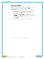
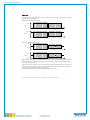
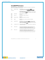
103-52-390-005-EH-0909.pdf
smartMODULPREMIUM
User Manual
Anleitung_SM-Premium_V2.4 | 15.9.2009/ M.N. | Issued without guarantee, all rights reserved
1
103-52-390-005-EH-0909.pdf
Content
1.
General
Page 3
2.
Connections on the smartMODULPREMIUM
Page 4
3.
Connections with smartMODULPREMIUM
Page 6
4.
smartMODULPREMIUM output signals
Page 7
4.1. Analogue signal with 0-20mA / 4-20mA or 0-1V / 0-2V (resistance)
Page 7
4.2. RS485 interface
4.2.1. smartMODULPREMIUM register assignments
4.2.2. Communication via the Modbus Open Protocol
4.2.3. Example of register read offs
Page 8
Page 10
Page 12
Page 16
5.
Start up phase
Page 18
6.
Wire break between smartMODUL and interface electronics
Page 18
7.
Using smartMODULPREMIUM with voltage output
Page 19
8.
Calibrating the smartMODULPREMIUM
9.
Page 20
8.1. Zero point calibration
Page 21
8.2. End point calibration
Page 22
Measuring cell with gas line
Page 23
10. General information
Page 24
Technical data
Page 25
Anleitung_SM-Premium_V2.4 | 15.9.2009/ M.N. | Issued without guarantee, all rights reserved
2
103-52-390-005-EH-0909.pdf
1. General
smartMODULPREMIUM combines the advantages of smartMODULFLOW with the circuit board of
smartMODULCONNECT.
This combination offers not only a variety of interfaces for data exchange, but also the option of
controlled perfusion of the sensors via a gas inlet and outlet.
Based on the physical measurement of infrared absorption, the device is not only highly selective
but also provides high levels of accuracy and reliability when measuring gas concentration. Its
compact construction and low maintenance needs make it ideal for use even under very difficult
conditions.
The smartMODULPREMIUM is ideal for creating a sensor system for measuring explosive or
poisonous gases, supplying signals that can be read off either via MODBUS ASCII, as linear
analogue current or output voltage.
The rugged housing guarantees that the test gas remains within the measuring cell and provides
the system with mechanical protection.
All smartMODULPREMIUM devices can be used with the following outputs:
-
4-20mA
0-20mA
0-1.0V
0-2.0 V
RS 485
(3-wire)
(3-wire)
combined with a 50 Ohm resistance
combined with a 100 Ohm
communication via MODBUS ASCII
The range of different signal outputs makes integration of the device into existing systems
remarkably simple, reducing integration and development costs.
Given the wide range of gasses and their concentrations for which the smartMODUL has already
been developed, smartMODULPREMIUM from smartGAS Mikrosensorik GmbH offers the optimal
basis for universal implementation as top quality IR sensory technology.
Anleitung_SM-Premium_V2.4 | 15.9.2009/ M.N. | Issued without guarantee, all rights reserved
3
103-52-390-005-EH-0909.pdf
2. Connections on the smartMODULPREMIUM
smartMODULPREMIUM is supplied with an operational power supply of 12 to 30V DC. Trouble-free
functionality is guaranteed within this range.
Despite internal stabilization, voltage supply fluctuation should be limited.
In some cases, such as in plants where heavy loads are switched, the appropriate precautions
need to be taken.
The various connections in power supply and output signals are combined in socket ST1.
Figure 1. Power supply connections
Connections on ST1 are designated as follows:
V+
I
GND
RS+
RS-
Æ
Æ
Æ
Æ
Æ
power supply connections (12V - 30V DC).
connection for power output (selectable as 0-20mA or 4-20mA).
ground/earth for V+, I and RS485.
positive signal level for integrated RS485 interface.
negative signal level for integrated RS485 interface.
Anleitung_SM-Premium_V2.4 | 15.9.2009/ M.N. | Issued without guarantee, all rights reserved
4
103-52-390-005-EH-0909.pdf
The measuring cell and interface circuitry are connected by a 30cm data cable.
smartMODULPREMIUM can be supplied with cabling up to a metre length on request.
The connection is made with a four-pole push connector.
Figure 2. 4-pole connector
Anleitung_SM-Premium_V2.4 | 15.9.2009/ M.N. | Issued without guarantee, all rights reserved
5
103-52-390-005-EH-0909.pdf
3. Connections with smartMODULPREMIUM
smartMODULPREMIUM starts automatically after the start-up phase. (Section.4).
Connections and signal output for the smartMODULPREMIUM are via the ST1 plug. For operation
and use of the current output, the sensor must first be installed and connected.
To avoid faults and possible damage to the device, we recommend adherence to the following
sequence of operations:
1.
Install smartMODULPREMIUM in the desired application, ensuring sufficient distance
from conducting components to avoid short-circuits and possible damage.
2.
Remove the green plug from the ST1 socket. The connections and clamping screws are
now easy to reach.
3.
Connect the power supply to V+ and GND. Connect the signal cable for current output I
and GND. GND is the common ground for the power supply and current signal. Make
sure that the sequence of the connections on the plug corresponds to that on the circuit
board (make sure the plug is inserted correctly!).
4.
re-connect the ST1 plug.
The smartMODULPREMIUM starts automatically with the start-up phase (see Section 4).
Anleitung_SM-Premium_V2.4 | 15.9.2009/ M.N. | Issued without guarantee, all rights reserved
6
103-52-390-005-EH-0909.pdf
4. smartMODULPREMIUM output signal
4.1 Analogue signal with 0-20mA / 4-20mA or 0-1V (0-2V (resistance)
There are two options for indicating measurement values as current output. Firstly, it is possible
to use a range of 0-20mA, combined with a resistance to produce a linear voltage signal. The
second option is measurement output with 4-20mA. In this version, it is easier to detect a wire
break, loose connection or sensor failure.
The settings for the output signal are described in the following:
a)
0-20mA
Æ Jumper JP3 is in place (as supplied).
Figure 3. Working range 0-20mA
b)
4-20mA
Æ Jumper JP3 not in place.
Figure 4. Working range 4-20mA
Select the range of output current for signal transfer you need for your application. Switching
between the two ranges is possible once the device is unplugged from the power supply.
.
Anleitung_SM-Premium_V2.4 | 15.9.2009/ M.N. | Issued without guarantee, all rights reserved
7
103-52-390-005-EH-0909.pdf
4.2 RS485 Interface
The smartMODUL PREMIUM has a RS485 interface (half-duplex). Via this interface the device can
communicate via three lines:
x
RSinterface’s inverted data line
x
RS+ interface’s non-inverted data line
x
GND interface reference potential. This must be used for communication via the
interface when the participant does not have the same zero potential (e.g.
galvanic separation).
The interface can be accessed via this 5-pole plug connector.
Figure 5. RS485 interface connections
NOTE:
The RS- and RS+ lines should be bridged by at least 30 cm cable with 120 resistance inline.
RS485 settings
Baud rate:
Data bits:
Stop bits:
Parity:
Timeout:
Retries:
2400
7
1
Even
1000ms
3
TIP: In some cases it is necessary to increase the Timeout time to 1.5s.
Anleitung_SM-Premium_V2.4 | 15.9.2009/ M.N. | Issued without guarantee, all rights reserved
8
103-52-390-005-EH-0909.pdf
Signal trace
The signal traces at RS485 interfaces can vary greatly. The following are two examples of signals
in the data line of the RS485.
Example 1: RS232/RS485 converter
+4.7V
RS0V
70-73ms
70ms
+4.7V
RS+
0V
Example 2: USB/RS485 converter
+4.7V
RS0.4V
70-73ms
70ms
+4.7V
RS+
0.4V
High flexibility of amplitude is available because with RS485 the potential difference of both data
lines is evaluated. In the above examples it can be seen that the difference between RS- and RS+
is 0V (inactive) or 2V (active).
A short pause of max 100ms can occur. The module then replies. This depends on how many bytes
need to be read off: if only one byte is read then the module reply lasts approx. 70ms. Reading off
more bytes correspondingly increases the reply phase.
The amplitude of the data line depends on the RS485 interface used.
Anleitung_SM-Premium_V2.4 | 15.9.2009/ M.N. | Issued without guarantee, all rights reserved
9
103-52-390-005-EH-0909.pdf
4.2.1 smartMODULPREMIUM register assignments
The sequence of registers in the current version is listed below; as they appear in the Host SW.
Section 4.2.3 has examples of reading registers.
0xC0
Modbus_address
Current Modbus status of smartMODULPREMIUM.
Standard address: see Page Error! Bookmark not defined.:
“Addresses”.
The addresses can be written and read.
After an address has been changed, subsequent communication
with the smartMODULPREMIUM is only possible via this address.
0x80 –
0x83
DeviceType
The type of device connected.
Read only.
0x86 –
0x89
Serial Nr
Serial number of device connected.
Read only.
0x84 –
0x85
SoftwareVersion
Software version of device connected.
Read only.
0x05
MOD
Assumed value for internal concentration calculation.
Read only.
0x0A
Konzentration
Concentration is stored in this register as a numerical value.
Depending on the smartMODULPREMIUM type a factor is still
required for the calculation, found in the QS certificate supplied
with every smartMODULPREMIUM.
0x03
T_module (0.1x°C)
Internal sensor temperature, as reference point for temperature
correction. Read only.
0x45
Alarm_Level
Provides the threshold trigger value for the main gas alarm,
referenced to the modulation value displayed for the
concentration of real gas. This modulation value is reduced by
one, entered in this register and can be freely set by the user.
0x44
Warn_Level
Provides the threshold trigger value for the gas pre-alarm,
referenced to the modulation value displayed for the
concentration of real gas. This modulation value is reduced by
one, entered in this register and can be freely set by the user..
Anleitung_SM-Premium_V2.4 | 15.9.2009/ M.N. | Issued without guarantee, all rights reserved
10
103-52-390-005-EH-0909.pdf
0x09
Status flags
Status flags indicate the states the module can adopt. Read
only.
Individual flags, read from right to left, mean:
Flag 0:
Flag 1:
Flag 2:
Flag 3:
Flag 4:
Flag 5:
Flag 6:
compensated.
Flag 7:
Test flag,
Warm-up,
Syserr,
Alarm,
Warn,
Start-up,
Korr,
value „1“ with device test
value „1“ approx. 10s after start
value „1“ device fault
value „1“ with main gas alarm
value „1“ with gas pre-alarm
value „1“ in the start-up phase approx. 90s
value „1“ when smartMODULPREMIUM is temperature-
mw_ok,
value „1“ when das smartMODULPREMIUM has been calibrated.
Flags 6 (Korr) and 7 (mw_ok) are internal flags, set for each process smartMODULPREMIUM during
production.
They also have a quality control role and are set to “1” when the smartMODULPREMIUM is
temperature compensated and has been calibrated.
Anleitung_SM-Premium_V2.4 | 15.9.2009/ M.N. | Issued without guarantee, all rights reserved
11
103-52-390-005-EH-0909.pdf
4.2.2. Communication with the smartMODULPREMIUM via Modbus Open Protocol
Reading off TTL signals provides access to a small fraction of the information logged by the
smartMODULPREMIUM.
Since smartMODULPREMIUM has a large amount of data potentially available it makes sense to use
a BUS protocol.
The Modbus Protocol basically works on the master/slave principle. The master (PC or μ
controller) sends a request to the slave (smartMODULPREMIUM), which in turn answers. The
duration of this phase, until all data is received, depends on how many registers need to be read.
As a rule, the smartMODULPREMIUM reacts to the request within 100ms. The character string is
sent directly, without reply pause. The slave does not send any data without a request.
The request is always first interpreted after dispatch by CRLF.
WARNING: Some programmes automatically send the CRLF; with most conventional
programmes this needs to be tagged onto the string manually!
The smartMODULPREMIUM sends no reply if it receives an incomplete request. This is also the case
when one or more registers are absent from a register set (section request). An adapted form of
the Modbus Protocol is used for smartMODULPREMIUM, differing from the standard version in that
one path is used for send and receive. This ASCII protocol uses a serial half-duplex connection.
Datagram structure
The following section describes how a request data string to smartMODULPREMIUM is constructed.
The example below shows the current modulation read off from a smartMODULPREMIUM with
address 160.
Example string looks as follows:
:A00300050001A6
Start
1 character
:
Address
2 characters
A0
Ctrl Com.
2 characters
03
Data
0-100 * 2 characters
00 05 00 01
checksum LRC
2 characters
A6
Note: Addresses, control commands and data are prefixed with “0x” and the actual address /
commands as “nn”. The “0x” merely indicates that the data is hexadecimal, but since the Modbus
Protocol ASCII is defined as hexadecimal, this information is superfluous and only the address or
command is transferred. The string contains no “0x” and “0x05” becomes “05”.
Anleitung_SM-Premium_V2.4 | 15.9.2009/ M.N. | Issued without guarantee, all rights reserved
12
103-52-390-005-EH-0909.pdf
Start:
As a rule datagrams start with a colon“:”, irrespective of whether they are requests or replies.
Address
This defines to which device address the string is assigned. As standard, the device address is the
last two digits of the MODULPREMIUM serial number as delivered.
Ex.:
Serial number: 22-0800-486
Æ
device address: 86
Serial number: 52-0800-228
Æ
device address: 28
These are added to search for module addresses. Now any register (e.g. concentration) can be
requested from all module addresses (1-255) with a timeout of one second. A module with the
correct address responds by sending a reply. This reply includes the module address so that at the
end of the search cycle it is possible to see by processing the reply which module addresses are
currently connected to the bus system.
Control commands
The control commands indicate what needs to be done with the addresses detected. Basically the
MODULPREMIUM distinguishes between “ReadÆ0x03” and “WriteÆ0x06”.
The command in the example shown here is “Read Register” (0x03Æ03)
Data
The register number is sent in data as a parameter. In the example here it is “Start Address High
(0x00Æ00) / Low (0x05Æ05) and Number Register High (0x00Æ00) / Low (0x01Æ01)”.
The Start Address High” and “Start Address Low” indicate to which register address the control
command is directed; in this case, address 0005Æ0x05 “MOD”.
“Number Register High” and “Number Register Low” state how many registers beginning with
the start address should be read. Should 10 Registers be read, then 0010 needs to be entered.
Registers 05 to 14 are read and transferred. Data is transferred in its hexadecimal form!
The number of bytes doubles after conversion to from ASCII to Hex.
Anleitung_SM-Premium_V2.4 | 15.9.2009/ M.N. | Issued without guarantee, all rights reserved
13
103-52-390-005-EH-0909.pdf
Checksum
The checksum calculates according to a LRC method (Longitudinal Redundancy Check) from all
the bytes sent without CR and LF characters.
The bytes are added and the sum subtracted from 0xFF.
1 is added to the result, making the LRC complete.
In the example shown here the value is “A6”
The checksum is always transmitted with the data and recalculated by the recipient. Should a
value in the data set become corrupt, then the checksum calculated by the recipient would be
different from that sent. The data set in this case would be unusable.
A reply to the string above would look as follows:
:A00302000109
Start
Address
Crtl. Com
No. of bytes
transferred
1 character
2 characters
2 characters
2 characters
:
A0
03
02
Data
Checksum LRC
0-100 *
2 characters
00 01
2 characters
09
The following is an example of a checksum calculation.
(Command: Read register 5 onlyÆ Modulation MOD):
Data[0]:=’:’; Data[1]:=’A’; Data[2]:=’0’; Data[3]:=’0’; Data[4]:=’3’;
Data[5]:=’0’; Data[6]:=’0’; Data[7]:=’0’; Data[8]:=’5’; Data[9]:=’0’;
Data[10]:=’0’; Data[11]:=’0’; Data[12]:=’1’
Length=12;
Note: LRC and CRLF do not belong to the data. CRLF is not included in the LRC calculation!
1.
Lrc=0;
For(i=1;i<Length;i++)
2. Lrc=Lrc+data[i];
//(checksum is set to 0)
//(All transferred bytes are binary added with overflow (8
Bit). Example: 200+200=400. With 8 only 256Æ 144 is
written = Lrc.
(In this example the rest sum is 90.)
3.
Lrc=0xFF-Lrc;
//(From 255, subtract sum value (90))
4.
Lrc=Lrc+1;
//(255-90+1=166=A6 in Hex (checksum request)
Anleitung_SM-Premium_V2.4 | 15.9.2009/ M.N. | Issued without guarantee, all rights reserved
14
103-52-390-005-EH-0909.pdf
Example
String
:A00300050001
Converted to ASCII values
A = 65
0 = 48
1 = 49
3 = 51
5 = 53
Calculation:
A+0+0+3+0+0+0+5+0+0+0+1
65+48+48+51+48+48+48+53+48+48+48+49=602
602-256=346
346-256=90 (Rest!)
Checksum:
255-90+1=166 = A6 in hex.
After calculation of the checksum the following would be sent:
:A00300050001A6
The reply would yield, for example, the following:
:A00302002008 (checksum 08 from reply data packet)
The structure is as follows:
: Start of the frame
A0 -> Address sender
03 -> Register data
02 -> No. bytes (HEX!)
0020->Register data
08-> checksum reply
Anleitung_SM-Premium_V2.4 | 15.9.2009/ M.N. | Issued without guarantee, all rights reserved
15
103-52-390-005-EH-0909.pdf
4.2.3 Examples of registers read offs
All the following refer to a smartMODULCONECT with address 160.
x Read off Device Type register
Send the following string:
:
Start
A0
Adr.160
03
read
00 80
Startregister
00 04
Register no.
A0
checksum
Reply:
:
Star
t
A0
Adr.16
0
03
read
08
no. bytes
53
S
4D
M
2D
-
43
C
4F
O
32
2
20
20
64
checksum
Data is transferred as characters and can be converted using an ASCII table.
x Read off Serial No. register
Send the following string:
:
Start
A0
Adr.160
03
read
00 86
Start
register
00 04
Register no.
9A
checksum
Reply:
:
Star
t
A0
Adr.16
0
03
read
08
no. bytes
32
2
30
0
08
08
00
00
019A
410
0000
99
checksum
The first
two bytes are transferred as characters and can be converted using an ASCII table.
The third and fourth bytes are transferred as hexadecimal values and each yields a twodecimal place number.
The fifth and sixth bytes are summed as a hexadecimal value and produce a three-decimal
place number.
x Read off Status flags register
Send the following string:
:
Start
A0
Adr.160
03
read
00 09
Start
register
00 01
register no.
A2
checksum
Reply:
:
Star
t
A0
Adr.16
0
03
read
02
no. bytes
00C0
11000000
F7
checksum
The two data bytes are summed
and transferred as hexadecimal value. If this value is converted to binary number then the
flags raised can be determined.
x Read off Software Version register
Send the following string:
:
Start
A0
Adr.160
03
read
00 84
Start
register
00 02
register no.
9E
checksum
Reply:
:
Star
t
A0
Adr.16
0
03
read
04
no. bytes
33
3
2E
.
33
3
30
0
22
checksum
The data is transferred
as characters and can be converted using an ASCII table.
Anleitung_SM-Premium_V2.4 | 15.9.2009/ M.N. | Issued without guarantee, all rights reserved
16
103-52-390-005-EH-0909.pdf
x Read off Concentration register:
Send the following string:
:
Start
A0
Adr.160
03
read
00 0A
Start
register
00 01
register no.
9A
checksum
Reply:
:
Star
t
A0
Adr.16
0
03
read
02
no.bytes
01C8
456
EE
checksum
The two data bytes are summed
and transferred as a hexadecimal value. If this value is converted to a decimal number, the
concentration can be determined (here - 456ppm).
Anleitung_SM-Premium_V2.4 | 15.9.2009/ M.N. | Issued without guarantee, all rights reserved
17
103-52-390-005-EH-0909.pdf
5 Start-up phase
After power supply and current output have been connected to smartMODULPREMIUM the sensor
starts a warm-up phase. This lasts approximately 90 seconds and serves as an internal check of
all components and routines.
The following states can occur during the warm-up phase, depending on the operating system
chosen:
4-20mA:
First approx. 2mA, then a jump to approx. 4mA.
After approx. 90 seconds I 4mA, depending gas concentration present.
0-20mA:
First 0mA. After approx. 90 seconds I 0mA depending on gas concentration
present.
When the warm-up phase has finished and all test routines completed trouble-free,
smartMODULPREMIUM automatically switches to normal operation and displays gas concentration
measured as linear current.
6. Wire break between smartMODULPREMIUM and interface electronics
If the connection between a smartMODULPREMIUM and the interface electronics is interrupted
(accidental separation or wire break) the following state is displayed at the current output:
Operating with 4-20mA Æ Output current is frozen at 2mA.
Operating with 0-20mA Æ Frozen at the last delivered current value.
Depending on operating current and switching values, this state can be used as error recognition.
If the fault is rectified, smartMODULPREMIUM automatically re-enters the normal warm-up phase
and then switches over to normal operation when complete, as described in Section 5.
NOTE:
If operation with 0-20mA has been chosen the frozen current value is maintained until end of the
warm-up phase.
Trouble-free wire break recognition is general only possible operating with 4-20mA!
Anleitung_SM-Premium_V2.4 | 15.9.2009/ M.N. | Issued without guarantee, all rights reserved
18
103-52-390-005-EH-0909.pdf
7. Using smartMODULPREMIUM with voltage output
In some applications it is necessary to convert the smartMODULPREMIUM output signal into a
linear voltage signal so that it can be evaluated.
This is easily achieved by inserting a precision resistance into the voltage output (between I and
GND).
The result drop-off in voltage across the resistance reflects the concentration of the gas measured.
Depending on operating current the following voltages can be set:
4-20mA
Æ
Æ
0.2V – 1.0V
0.5V – 2.0V
0-20mA
Æ
Æ
0V – 1.0V
0V – 2.0V
with a 50: resistor
with a 100: resistor
with a 50: resistor
with a 100: resistor
NOTE:
The maximum resistance possible for producing output signals is 125:.
Anything larger would give rise to measurement error, or even in some cases, damage to
smartMODULPREMIUM. The maximum permitted output voltage is 2.5V and should not be
exceeded.
Anleitung_SM-Premium_V2.4 | 15.9.2009/ M.N. | Issued without guarantee, all rights reserved
19
103-52-390-005-EH-0909.pdf
8. Calibrating smartMODULPREMIUM
Many applications require sensor calibration after the first operational run up or at regular
intervals thereafter.
There are basically two types of calibration to consider.
1. Zero point calibration
This serves to indicate the normal zero gas concentration to the sensor. It is not necessarily
0% gas; measuring atmospheric CO2 results in a concentration of 350 ppm – 380 ppm.
Therefore the selection of zero gas is extremely important.
2. End point calibration
The end point calibration serves to set the upper measurement value (UMV).
This is the maximum value that can be reliably detected and measured by the sensor. When
selecting sensors it is important not to set the UMV too small as this may result in
inaccuracy and erroneous measurement.
IMPORTANT: smartMODULPREMIUM must be run for at least 15 minutes before calibration!
Anleitung_SM-Premium_V2.4 | 15.9.2009/ M.N. | Issued without guarantee, all rights reserved
20
103-52-390-005-EH-0909.pdf
8.1. Zero point calibration
1.
Perfuse the sensor with zero gas, making sure the measuring cuvette has been fully purged
and only zero is present.
2.
Place a jumper on positions 1-2 in 1J
JP4 and wait approx. 20 seconds. The value of the output
current should be either 0mA or 4mA (depending on operating system), or drop to 0V or 0.5V
(e.g. with 100:). Removing the jumper ends calibration and the new value is saved in the
sensor.
WARNING: Only run calibration with zero gas, otherwise subsequent measurements may be
faulty.
Figure 6. Zero calibration (Jumper on JP4, PIN 1-2)
Anleitung_SM-Premium_V2.4 | 15.9.2009/ M.N. | Issued without guarantee, all rights reserved
21
103-52-390-005-EH-0909.pdf
8.2 End point calibration
1.
Flood smartMODULPREMIUM with the gas concentration corresponding to the upper
measurement value and make sure no residual gas is present in the cuvette.
Place a jumper on positions 2-3 on JP4 and wait approx. 20 seconds. Output should increase
to 20mA or 2.0V. Removing the jumper ends calibration and the new value is saved in the
sensor.
WARNING: Only run calibration with the appropriate gas concentration for the measurement
range given, otherwise subsequent measurements may be faulty.
Figure 7. Voltage calibration (Jumper auf JP4, PIN 2-3)
Anleitung_SM-Premium_V2.4 | 15.9.2009/ M.N. | Issued without guarantee, all rights reserved
22
103-52-390-005-EH-0909.pdf
9.Measuring cell with gas line
The smartMODULPREMIUM housing is made of aluminium to protect the sensor from mechanical
damage and is with fitted with gas lines to ensure the measuring cell is flooded with the
appropriate gas.
The smartMODULPREMIUM housing is made of aluminium to protect the sensor from mechanical
damage and is with fitted with a gas line connectors (inlet and outlet) to allow perfusion of the
smartMODULPREMIUM (see Figure 8).
Tubing with an internal diameter of 3mm and external diameter of 5mm is needed to connect up
to the measurement cell. Ensure that tubing is securely attached to the inlet and outlet
connectors.
OUTLET
INLET
Figure 8: Measurement cell with gas inlet and outlet
Adhere to the directional designation of INLET and OUTLET; switching the direction of gas flow
through the cell could lead to erroneous results.
NOTE:
Ensure the correct type of tubing is used. In some applications, corrosive gases occur and could
cause problems with the tubing material.
Do not perfuse the smartMODULPREMIUM at a gas flow rate of greater than 1l per minute!
Anleitung_SM-Premium_V2.4 | 15.9.2009/ M.N. | Issued without guarantee, all rights reserved
23
103-52-390-005-EH-0909.pdf
10. General information
Connections not discussed in this document include:
x
x
x
x
JP1
JP2
ST2
ST4
Must be left free!
Production-relevant
USB, production-relevant
Keep free!
These connectors are production-relevant and may not under any circumstances be used for
normal operation. Misuse or attempts to use these connectors will damage the electronics and
void the manufacturer’s guarantee!
Figure 9. Additional connectors
smartMODULPREMIUM may only be used with the smartMODUL supplied.
To ensure and maintain the trouble functionality and compliance with the conditions of the
manufacturer’s guarantee do not attempt to exchange or replace the smartMODUL supplied with
another smartMODUL
.
Anleitung_SM-Premium_V2.4 | 15.9.2009/ M.N. | Issued without guarantee, all rights reserved
24
103-52-390-005-EH-0909.pdf
Technical data
Product features
Measurement principle
Measurement range
Cuvette dimensions:
H)*
Gas line connectors
NDIR (dual beam)
dependent on model (see list of measurable gases)
Length (model dependent) x 28 X 42 mm (L x W x
PCB: 72 x 55 x 21 mm (L x B x H)
3mm internal, 5mm external
Technical features
Response time
< 10 s (at 0.1l/min)*
Accuracy
± 2% upper range value*
Stability
±2% upper range value* over 12 month period
Reproducibility
<2% upper range value*
Linearity error
<1% upper range value*
Error recognition (wire break Modul-Connect): - output current 2mA (4-20mA)
- frozen output current (0-20mA)
Calibration
zero and voltage by jumper
Operating temperature
-10° C - 40° C
Pressure
950 – 1050hPa**
Humidity
0 – 95% rel. humidity
Warm-up time
< 90s (start up time)*
15 minutes (full specification)*
Perfusion rate
0.5 – 1 l/min
Communication
Analogue output signal
Digital output signal
0-20mA linear
4-20 mA linear
0-1 V linear (with 50 )
0-2 V linear (with 100 )
Modbus ASCII via RS485
Electrical data
Power supply
Current demand
Max load
12-30Volt DC
max. 140mA
125
*
**
depending on model type
entering location in register 0x52 the application range in terms of pressure can be
increased.
Anleitung_SM-Premium_V2.4 | 15.9.2009/ M.N. | Issued without guarantee, all rights reserved
25
We are here for you. Addresses and Contacts
Sales Switzerland
Sales Germany
Sales Austria
Baden-Württemberg Region
(Postcode 60000 – 79999)
Rest of Germany
Matthias Rüegg
Ruhbergstrasse 32
CH-9230 Flawil
Dieter Hirthe
Mühlweg 23
D-71554 Weissach i.T.
Kurt Stritzelberger
Neumarkter Str. 86a
D-81673 Munich
Kurt Stritzelberger
Neumarkter Str. 86a
D-81673 Munich
Tel.
Mobil
Fax
Phone + 49 (0) 71 91 49 60 58
Mobile + 49 (0) 163 76 27 430
Fax
+ 49 (0) 71 91 93 31 88
Phone + 49 (0) 89 260 38 47
Mobile + 49 (0) 17 18 03 41 35
Fax
+ 49 (0) 89 43 10 91 91
Phone + 49 (0) 89 260 38 47
Mobile + 49 (0) 17 18 03 41 35
Fax
+ 49 (0) 89 43 10 91 91
[email protected]
[email protected]
[email protected]
Sensors
Power Supplies
E-Components
Drives
Physical Sensors
Peter Felder
Phone + 41 (0) 44 877 35 05
[email protected]
DC-DC Converters
Switching Power Supplies
DC-AC Inverters
Sebastiano Leggio
Phone + 41 (0) 44 877 35 06
[email protected]
Current Converters
Motors
Claudio Chiffi
Phone + 41 (0) 44 877 35 03
[email protected]
DC Drives
AC Asynchronous Motors
Stepper Motors
Servomotors
Electrical Linear Drives
DC Controllers
Servo Controllers
Frequency Converters
Switched-mode Power Supplies
Couplings
Claudio Chiffi
Phone + 41 (0) 44 877 35 03
[email protected]
+ 41 (0) 44 877 35 18
+ 41 (0) 76 491 66 66
+ 41 (0) 44 877 35 19
[email protected]
Sales Other Countries
PEWATRON AG
Thurgauerstrasse 66
CH-8052 Zurich
Phone + 41 (0) 44 877 35 00
Fax
+ 41 (0) 44 877 35 25
[email protected]
www.pewatron.com
Geometrical Sensors
Eric Letsch
Phone + 41 (0) 44 877 35 14
[email protected]
Supporting your great ideas
Man Machine Interface
Measurement Probes
Sebastiano Leggio
Phone + 41 (0) 44 877 35 06
[email protected]
www.pewatron.com