1
15-413 Software Engineering
Carnegie Mellon University
School of Computer Science
http://sierra.se.cs.cmu.edu/STARS
Handout 2
24 August 1999
Problem Statement
STARS: Sticky Technology for Augmented Reality Systems
1. Introduction
With the increasing complexity of systems such as automobiles, trucks, airplanes, trains
or power plants, access to maintenance procedures at the place of work is essential.
Current maintenance procedures for these systems are costly and inefficient.
Information quickly goes out-of-date and maintenance manuals are often only available
as hardcopy or on workstations far away from the airplane or automobile. In addition,
the maintenance information is not tailored to the actual work order, requiring the
mechanic to perform unnecessary steps before viewing the information that is actually
needed to perform the repair.
2. The Problem
The F/A-18 "Hornet" Program Office, PMA-265, has been asked to reduce the cost for
logistics support and maintenance while improving or at least maintaining current
aircraft readiness.
The cost of electronic data required for the aircraft, especially when it has already
been authored in a proprietary format or is available only in paper form, is enormous.
Some solutions to the problem of reducing costs are available. For example, an
Automated Conversion System (ACS), when coupled to an Interactive Electronic
Technical Manual (IETM) authoring tool, lowers technical manual conversion cost
significantly.
This process has allowed the program office to lower by more than 33% the cost of
converting its F/A-18 C&D organizational-level technical manuals to IETMs. However,
the program office cannot afford to do the same for F/A-18 A&B technical manuals and
related data (e.g., logbooks) because they are all paper-based documents, i.e., not
available in electronic form.
Another source of high costs is the business process currently used to acquire the data
for an aircraft. Today, the prime contractor (e.g., Boeing for the F/A-18) receives the
technical data for the various subsystems from the Original Equipment Manufacturers
(OEMs), such as General Electric for F/A-18 engines. The system prime contractor then
integrates the data into the technical manuals that get delivered with the system. The
Page 1
labor and overhead rates of these aerospace contractors are very high and are
compounded by the charges added by the system prime to integrate, provide quality
control (QC), and deliver the technical manuals.
3. Proposal
In this project we are asking you to build a system called STARS - Sticky Technology
for Augmented Reality Systems. STARS attempts to reduce the cost of logistics support
and maintenance while improving or at least maintaining current aircraft readiness.
To address the problem, we propose the implementation of two major processes:
developing & managing interactive electronic technical manuals and performing
maintenance with advanced capability IETMs.
The process of developing&managing of IETMs itself consists of three activities: 1)
authoring of IETMs, 2) release of IETMs to maintenance organizations and 3) authoring
and release workflow management.
The authoring of IETMs from paper documents is to be done in two stages. The
digitizing stage is to be done by Alaskan Native and American Native firms. They will
use text and graphic conversion tools and apply QC techniques to produce electronic
data, which is then provided to IETM authoring systems. The White House, Congress,
and the Native American Marketing Corporation (NAMCOR) are backing this effort to
provide meaningful employment for Alaskan Natives and American Natives without
leaving their current communities.
The conversion stage, performed by F/A-18 engineers and technical manual writers at
the F/A-18 Fleet Support Organization in San Diego, California. Converts the nowdigitized data into IETMs. Over time, this conversion may also be done by the Alaskan
Natives and American Natives.
The digitized data is then converted into IETMs using the authoring systems located at
the F/A-18 Fleet Support Organization at San Diego, CA where F/A-18 engineers and
technical manual writers do the work. Over time, this authoring may also be done by
the Alaskan Natives and American Natives.
IETM authoring is also done by the OEMs and Boeing (for the aircraft itself) using a
standard authoring system and data direct from the engineering CAD systems used in
the manufacturing design process.
The output of the various IETM authoring efforts is transferred electronically to a
central IETM Integration Database at the F/A-18 Fleet Support Organization for QC
and integration into a release version of the IETMs. The release version is then
transferred electronically to the IETM Operational Database where the new IETM
versions are used to incrementally update the IETMs in use by the F/A-18 maintenance
organizations. This is done by electronically updating the IETM databases in those
Page 2
organizations.
This IETM release process is to be supported by a Distributed Development and
Management System (DDMS) that provides support for collaboration and coordination
among the various organizations, visibility into the structure and state of the IETMs
under development, awareness of the process state, and validation of the IETM
development tool set.
The process of performing maintenance with advanced IETM capabilities consists of
two activities: 1) IETM-based inspections and 2) IETM-based repair. In the F/A-18
maintenance organizations, inspections of the aircraft are performed with check lists
provided in one section of the IETM. The result of an IETM-based inspection is a
listing of discrepancies that are assigned as repair tasks in work orders for technicians
to correct them (Repair tasks are also created by system faults identified during flight or
from periodic maintenance schedules). The technician makes an IETM-based repairs
by interactively following a procedure provided in another section of the IETM.
4. Scenarios
In the following sections we describe several scenarios that the STARS System must
support to deal with the above processes. These scenarios must be demonstrated at
the end of this project.
4.1 Authoring of IETMS
Jim, one of the Document Specialists from the Arctic Slope Regional Corporation
(ASRC) receives the task to convert the paper technical manual to digital data for the
GE 404 engine used in the F/A-18 A&B aircraft. He scans the technical manual into the
Automated Conversion System (ACS) to convert the text and into a companion tool to
convert the graphics. Jim then checks the digitized document and corrects the errors
introduced by the ACS and graphic tool. The digitized document is then transferred to
Anne, a Quality Controller, who checks the digitized document and returns it Jim for
more corrections. After that iteration, the document is signed out for release to the next
step in the process, the addition of links and structure to the digital document using an
AIMSS IETM authoring system by a Technical Manual Writer.
4.2 Process Workflow Management
Court, the Process Manager at ASRC checks the status of work in his Distributed
Development and Management System (DDMS) and notes that the GE 404 engine
technical manual digitized document is due out today. He checks with the Document
Specialist and finds that the document will be ready in one hour. He then initiates a
Video Teleconference (VTC) with Andrew, the Process Manager at the F/A-18 Fleet
Support Organization at San Diego, and they coordinate transferring the engine
document to the IETM Integration Database at the Fleet Support Organization.
At the Fleet Support Organization, the digitized document is transferred to the AIMSS
Page 3
IETM authoring system and converted into an IETM by Sam, a Technical Manual
Writer. Using the DDMS, the IETM is checked by Anne, the quality controller. An
engineer from Boeing is brought into a VTC to correct a technical detail in a procedure.
Finally, the new IETM is signed off, and again using the DDMS, the IETM is transferred
electronically for integration into a release version of the IETMs and final QC.
The manager of the IETM Integration Database process coordinates with the IETM
Operational Database manager using the DDMS and the release version is then
transferred electronically to the IETM Operational Database for release to fleet
maintenance organizations.
4.3 Release to maintenance organizations
The manager of the IETM Operational Database authorizes the new IETM versions to be
incrementally added to the IETMs in use by the F/A-18 Maintenance Organizations.
This is done by electronically updating the IETM servers in those organizations.
4.4 Inspections
Airman Smith reports to work at his Fighter Attack squadron aboard the USS Carl
Vinson and logs into the maintenance computer in his Airframes shop to see what jobs
have been assigned to him. He sees that his first work order is to perform a 14 day
periodic corrosion inspection of an F/A-18E aircraft, bureau number 176089. According
to the computer, this aircraft is parked in Hangar Bay 1. He dons his new wireless
Portable Electronic Display Device (PEDD) inspection assistant and performs a quick
calibration and operational checkout before heading down to the Hangar Bay to
perform his corrosion inspection. Once at the aircraft, Airman Smith begins the
inspection by reading IETM instructions from his Head-Mounted Display (HMD). As
he looks over each part of the aircraft on the inspection list, he enters discrepancies by
touching the part of the aircraft which has a problem, and then selecting the appropriate
discrepancy (corrosion, crack, fluid leak, etc.) and severity (minor, major) from a short
list. The system notes the location of the discrepancy on the aircraft based upon the
inputs from Airman Smith's data glove. The discrepancy is then entered in the system
as a virtual "sticky note" on the computer model of the aircraft. The sticky notes
contains all the necessary details. Once Airman Smith has completed the inspection, he
returns to his Airframes shop where he downloads the inspection results into the
maintenance computer system. His discrepancies are then incorporated into work
orders by Maintenance Control for dispatch to the appropriate work centers for repair.
4.5 Unscheduled Maintenance
Aviation Electronics Technician First Class (AT1) Chandler is beeped on her wireless
PEDD to proceed to the Flight Deck and trouble-shoot a problem with the APG-73 radar
on aircraft 301. She needs to determine if the aircraft can be made mission ready for a
flight in 65 minutes. In the three minutes it takes Chandler to reach the aircraft, her
her PEDD has downloaded the work order with the problem reported on the radar and
the troubleshooting IETMs. As Chandler crawls under the aircraft to reach one of the
Page 4
system components mounted inside the belly of the aircraft, the area becomes too tight
to use her HMD, so she switches to audio control. The trouble-shooting steps are then
read to AT1 Chandler through her earphones. By carrying on a dialogue with the
PEDD, the trouble shooting IETM leads her to discover that the Radar CPU is
malfunctioning and needs to be replaced.
She transmits this information to her supervisor requesting that the spare part be
delivered to the aircraft by the other technican required to aid in the repair. Her
supervisor, Senior Chief John, checks with both Material Control and Maintenance
Control, who finds that an acceptable spare CPU is available and that the work can be
accomplished in time for the aircraft to launch in 42 minutes. John then notifies
Chandler to start removing the defective CPU and dispatches AT2 Nusebaum to obtain
the replacement CPU and deliver it to the aircraft. Together, the technicans remove the
defective unit and replace it with the spare. AT1 Hartley from QC verifies that the
repair is correct and all involved apply electronic signatures to the work order releasing
the aircraft for its next mission with 12 minutes remaining to fuel and arm. Nusebaum
takes the removed component to turn in for repair while Chandler downloads all
information collected about the defective CPU from her wireless PEDD to the squadron
maintenance system server.
5. Preliminary Analysis
A preliminary analysis of the problem has already been performed which has resulted
in a set of functional and nonfunctional requirements describing the functions to be
performed by the system and constraints. Please use the scenarios and these
requirements as the basis for your interviews with the client during the requirements
analysis phase of STARS. We expect that the requirements will undergo several
incremental and iterative changes as a result of the analysis phase.
6. Functional Requirements
The STARS System must support the following functions:
• Create and annotate IETMS
• Provide a web-based display tools for IETMs
• Interface to ACS
• Interface to AIMSS
• Provide a review and quality control process for IETM documents
• Submit IETM documents to a IETM database
• Detect changes/annotations in IETM documents and notify the author
• Create a repair work order and notify subscriber for this type of repair
• Provide synchronous and asynchronus notification for the inspection/repair
scenarios
• Provide a web-based navigation through a 3-D model of the airplane
• Provide location information of the airplane (Where is the airplane and how is it
oriented with respect to a 3-D coordinate system?)
• Provide location information for the mechanics performing the maintenance (where
do the mechanics stand, and where do they look at?)
Page 5
• Provide an inspection checklist based on an IETM document
• Create an annotation ("Virtual sticky") by pointing to a specific location at the
airplane, indicating the discovered discrepancy and type of repair
• Provide audio/visual maintenance procedures as described in the work order
• Be able to locate the space stickies associated with an airplane
• Provide capabilities to perform the maintenance procedure interactively without
traditional input/output means (no keyboards, no mouse....)
7. Nonfunctional Requirements
When designing STARS, the following constraints must be taken into account:
• STARS must provide concurrent access by multiple users, accessing the system
locally and remotely. STARS applications run independently from each other as
separate processes, while still allowing the applications to communicate with each
other.
• The software architecture must be extensible to deal with the optional scenarios
• Any new code written as part of this development effort must be platform
independent.
• Model-based software engineering techniques have to be used. The application
domain must be modeled with UML. The system design and implementation must
be derived from the UML models developed during the analysis phase.
• Every STARS user has access to a portable/ wireless computer. The user interface
must take these conditions into account during the development phase.
8. Target Environment
It is expected that the development environment at Carnegie Mellon will be used for
demonstrating the prototype. The exact target environment will be specified by the
client during the requirements analysis phase.
9. Design Issues
A system dealing with the scenarios described in the previous sections will be complex
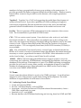
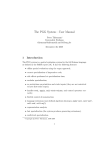
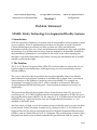
and will require a multi-team effort. We have decomposed the system into a software
architecture shown in Figure 1.
The authoring subsystem provides the capability to author and annotate IETMS which
can be viewed with a web-based display tool. It interfaces to existing commercial
products ACS and AIMSS that provide part of the required functionality. The work
flow subsystem provides a review and quality control process for IETM documents
submitted by authors. The subsystem also detect changes in IETM documents and
notifies the author. The subsystem is also used to provide notification for mechanics
when work orders have been created for them. The modeling subsystem allows
authoring of a description of an F18 airplane with a CAD tool, providing different
views, such as a wireframe view, that can be overlaid on the real airplane. The
augmented reality subsystem provides location information of the airplane with respect
Page 6
Authoring
Workflow
Modeling
Augmented
Reality
Notification
Inspection
Repair
Figure 1. Top Level System Design of STARS
to the mobile mechanic performing the maintenance. The inspection subsystem
provides the capability to do an inspection based on IETM documents. The mechanic
adds an annotation ("virtual sticky") to the repair location, by pointing to a specific
location at the airplane, indicating any discovered discrepancy and type of repair. The
repair subsystem provides the capability to perform maintenance procedures as
described in a work order. It helps the user to locate the stickies associated with a
specific airplane, and to perform the maintenance procedure interactively by using
voice input and output.
The notification subsystem provides a publisher/subscriber mechanism , which allows
creators of information to reach authors or mechanics within the organization that have
expressed their interest, explicitly or implicitly, in receiving this information.
10. Development Environment
The developers of the STARS System may make use of the facilities offered in the
clusters on the CMU Campus as well as the Software Engineering Laboratory located
in Building D, room 154A. While the clusters are shared with other students taking
other courses, the resources at the software engineering lab are to be used solely for the
development of the STARS System. The Software Engineering Laboratory offers a set of
9 PCs running Windows NT and Linux as well as 6 Macintosh running MacOS 8.6.
These machines are connected via a local Ethernet. The following software tools are
used during development.
Lotus Notes. This is a groupware tool, designed to facilitate communication between
Page 7
members of a large, geographically diverse group working on the same project. It
provides persistent document storage and address book functionality. Inherent security
features allow content to be provided over the Internet, with complex permission
options.
Together/J. Together/J is a CASE tool supporting the model-based development of
systems written in Java. It provides capabilities for UML modeling and supports
round-trip re-engineering between models and source code. It also automatically
generates relevant documentation off comments in the models and source code.
JavaDoc. This tool generates API documentation from the comments of Java source
code. The documentation is provided in HTML format.
CVS . CVS is a version control system. Users check out code, work on it, and check
functional code back in. The system allows for multiple users to be working on the
same code, and supports the merging of multiple changes by different users to the same
version of code. It uses a client-server model, allowing the checkout of code from
remote locations. CVS was originally linux-based, but a WWW interface (CVSWeb) is
now available.
ACS. ACS (Automated Conversion System) converts legacy technical manuals into
IETMs. ACS consists of a series of automated steps that minimize the human interaction
necessary to convert paper-based documents into IETMs. More information on ACS
can be found at http://www.lmco.com:80/lmis/level4/acs.html.
AIMSS. AIMSS (Advanced Integrated Maintenance Support System) is a tool for
constructing and authoring IETM databases, maintaining the databases, and using the
databases for the delivery of information to a user. The AIMSS authoring environment
provides the tools used to create, delete, modify, and maintain all aspects of an IETM
database development project. More information on AIMSS can be found at http://
www.htsc.com/AIMSS/AIMSS.HTML.
11. Teams
Several teams have been defined to work on the STARS prototype. A coach has been
assigned to each of these teams to guide them during the development. The initial
definition of responsibilities for each team is shown below.
11.1 Authoring (Coach: Grace Ritter)
• Create and annotate IETMs
• Provide web-based display tools for IETMs
• Investigate tools that can derive a DTD (Data technical documentation) from a
UML object model and vice versa.
• Interface to ACS and AIMSS
• Become familiar with IETM-based authoring and viewing based on SGML and XML
Page 8
11.2 Workflow (Coach: Grace Ritter)
• Provide a review and quality control process for IETM documents
• Submit IETM documents to a IETM database
• Detect changes/annotations in IETM documents and notify the author
• Create a repair work order and notify subscriber for this type of repair
• Provide synchronous and asynchronus notification for the inspection/repair
scenarios
• Investigate tools and products for the automatic creation of workflows such as
IETMs and work orders.
11.3 Modeling Team (Coach: David Garmire)
• Create a "real airplane" (Provide a physical model of an airplane)
• Provide a UML model of an airplane
• Provide a wireframe view
• Provide a web-based navigation through a 3-D model of the airplane
• Investigate web-based CAD modeling tools
11.4 Augmented Reality (Coach: Eric Stein)
• Provide location information for the airplane (Where is the airplane and how is it
oriented with respect to a 3-D coordinate system?)
• Provide location information for the mechanic performing maintenance (where do
the mechanics stand, and where do they look at?)
• Provide an overlay of the wireframe view onto the "real" airplane from the position
of the mechanic.
• Investigate technologies for location identification such as GPS.
11.5 Inspection Team (Coaches: Zia Syed and Tom Hawley)
• Perform an inspection based on an IETM document
• Create an annotation ("virtual sticky") by pointing to a specific location at the
airplane, indicating the discovered discrepancy and type of repair
• Add this annotation to a workorder.
• Investigate multimodal input devices such as datagloves and identification devices
such as component tags.
11.6 Repair Team ( Coaches: Pooja Saksena, Tom Hawley)
• Perform maintenance procedures described in a work order
• Locate the virtual stickies associated with an airplane
• Provide capabilities to perform the maintenance procedure interactively without
traditional input/output means (no keyboards, no mouse....)
• Investigate speech synthesis/recognition technologies for the interactive
performance of repairs at the repair site.
11.7 Architecture (Coach: Bernd Bruegge, Bill Scherlis)
• Model the STARS System as a set of services provided by each of the subsystem.
• Evaluate existing event services and recommend one to be used for the notification
Page 9
subsystem.
Develop notification subsystem
Define a configuration management scheme to be used with CVS during the project.
Design a plan for integration testing and system testing of STARS.
Integrate the documentation produced by the team.
Publish all deliverables on the project portal so they can be viewed online by the
client.
• Copy all documents and the STARS prototype onto a CD-ROM, to be delivered to
the client during the client acceptance test.
•
•
•
•
•
12. People Contacts
The clients for the project are Lt. Matt Herl from the F-18 program office, Mark Kramer
and Raymond LeBeau from the Navy Carderock Lab. The client liaison is Tom Hawley
from Carnegie Mellon University. Consultants for some of the problems associated with
the subsystems and development tools are also available. The consultants are:
• XML/SGML: Stephan Schoenig , [email protected]
• CSCW: Jane Siegel, [email protected]
• User Interface: Elaine Hyder, [email protected]; Jack Moffet
[email protected]
• Speech recognition: Alex Waibel ([email protected])
• Together-J: David Garmire, [email protected]
• CVS: Eric Stein, [email protected]
• Lotus Notes: Joyce Johnstone, [email protected]
13. Client Acceptance Test
This is a broad problem statement, and as such, all the functionality that has been
alluded to is not expected to be delivered in one semester. The client is willing to
discuss any of the requirements specified in this document. During the requirements
analysis phase of the project, the functional and nonfunctional requirements of an
acceptable prototype will be established. An initial prototype of the STARS system is
expected six weeks after the functional requirements have been established. The
delivery of the second prototype of the STARS system is expected at the end of the
semester.
14. Deliverables
The client expects a successful demonstration of the STARS prototype on December 9,
1999 in the Software Engineering Lab at CMU with remote observers around the world
viewing the demonstration in real time over the Internet.
A set of documents on a CD-ROM describing the requirements analysis (RAD), the
system design (SDD), object design (ODD), testing procedures (TM) and a user manual
of the STARS system will accompany the demonstration.
Page 10