1
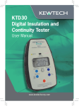
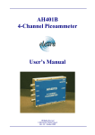
INSTRUCTION MANUAL
WARNING
PHASE ROTATION TESTER
K8031F
DESIGNATIONS
●Read through and understand instructions contained in this
manual before starting using the instrument.
●Save and keep the manual handy to enable quick reference
whenever necessary.
●Be sure to use the instrument only in its intended applications
and to follow measurement procedures described in the
manual.
●Be sure to understand and follow all safety instructions
contained in the manual. Failure to follow the above
instructions cause injury instrument damage and/or damage
to equipment under test.
The symbol
Indicated on the instrument means that the user
must refer to related parts in the manual for safe operation of the
instrument. Be sure to carefully read instructions following each
Symbol in this manual.
WARNING is reserved for conditions and actions that can
cause serious or fatal injury.
CAUTION is reserved for conditions and actions that can
cause injury or property damage.
SAFETY WARNINGS
This instrument has been designed and tested according to IEC
Publication 61010; Safety Requirements for Electronic Measuring
Apparatus. This Instruction manual contains warnings and
safetyrules which must be observed by the user to ensure safe
operation of the instrument and retain it in safe condition.
Therefore, read through these operating instruction before using
the instrument.
WARNINGS
1. Never open the instrument when making measurements.
2. If the instrument shows the following conditions, do not try to
make measurements and have the instrument checked for
inspection or repair.
a) Instrument shows visual damage.
b) Test leads are damaged.
c) Instrument can not be operated for intended measurements.
d) Instrument has been stored for a long period of time
under abnormal conditions.
e) Instrument has been subjected to severe shocks and
vibrations.
3. High voltage may be present with high energy levels.
Connect the leads to the system carefully with fingers behind
all finger guards.
4. If the all open phase lamps are not lit on, any phase may still
be live-be carefull.
CAUTIONS
1. Make sure to never apply a voltage more than 600V ACrms.
between the test leads of the instrument and earth to avoid
damage to the instrument.
2. Do not measure for more than five minutes when measuring
on 500V AC or more, although the instrument is designed for
the use 110V through 600V AC.
Measurement categories (Over-voltage categories)
To ensure safe operation of measuring instruments, IEC61010
establishes safety standards for various electrical environments,
categorized as CAT.Ⅰ to CAT.Ⅳ, and called measurement
categories. Higher-numbered categories correspond to
electrical environments with greater energy, So a measuring
Following symbols are used on the instrument and in the
instruction manual. Attention should be paid to each symbol to
ensure your safety.
Refer to this instructions in the manual.
This symbol is marked where the user must refer to the instruction
manual so as not to cause personal injury or instrument
damage.
Indicates an instrument with double or reinforced insulation.
instrument designed for CAT.Ⅲ environments gives greater
protection than one designed for CAT.Ⅱ.
CAT.Ⅰ: Equipment connected to a mains outlet socket
CAT.Ⅱ: Fault category level at a mains socket
CAT.Ⅲ: Fault category at distribution board level
CAT.Ⅳ: The circuit from the service drop to the power meter and
primary over-current protection device (distribution
panel).
Distribution Board CAT.Ⅲ
Incoming supply
Interior wiring
CAT.Ⅳ
CAT.Ⅰ
Socket
CAT.Ⅱ
Socket
CAT.Ⅱ
Equipment
FEATURES
●Two Functions in One Unit
K8031F is designed to check phase sequence. Lamps provided
on the unit will also tell you if a phase is open.
●Highly Reliable
Can check a wide range of 3-phase power source from 110V to
600V. Sealed against dust, the unit ensures trouble-free
performance.
●Functional Design
Small, Lightweight and portable. Designed for maximum ease of
operation and ruggedness.
(3) Make sure that all of the three lamps for phase check are on.
If so, there is no open phase. When any of the three lamps is
Not on there is open phase.
●Safety Design
No exposed metal parts. Safety features are incorporated
including the instant push button switch operation.
Open phase check
Lamp "L1" is not on
Open phase on terminal
where Red alligator clip
is connected.
Open phase check
Lamp "L2" is not on
Open phase on terminal
where Yellow alligator clip
is connected.
Open phase check
Lamp "L3" is not on
Open phase on terminal
where Blue alligator clip
is connected.
SPECIFICATIONS
Standard
: IEC 61010-1 CAT.Ⅲ 600V Pollution degree 2
Voltage
: 110V to 600V
Frequency
: 50Hz / 60Hz
Withstand Voltage : 5,550V AC for one minute
Time Limit for Continuous Use : Within 5 minutes in case voltage
is above 500V.
Dimensions
: 106 (L) x 75 (W) x 40 (D) mm
Weight
: Approx. 350g
Cord
: 1.2m each of Red (L1), Yellow (L2) and Blue
(L3) cord
Fuse
: 0.5A / 600V (F)
Accessories
: Instruction Manual, Carrying Case
OPERATING INSTRUCTIONS
(1) Connect colour coded alligator clips or prods to the terminals
of a 3-phase power source where a rotating electrical machine
such as a motor will be connected or input to a building.
(2) Press the push switch button located on top of the unit.
Keep this button pressed during phase sequence or open
phase check. When the push switch button is released it
immediately goes off.
*When the open phase check lamps are not on the rotating disc
does not turn.
(4) Check the rotating direction of the inside disc through the
phase sequence indication window.
*When the rotating disc turns counter-clockwise alternate the
connection of the two of the three alligator clips. Then, the
rotating disc will turn clockwise.
*When the rotating disc turns clockwise phase sequence is
L1,L2 and L3 in order of the power source terminals where the
Red, Yellow and Blue alligator clips are connected.
Please Note : New European harmonized phase colours are
as follows.
Red = Brown
Protective Earth = Green yellow
Yellow = Black
Neutral = Blue
Blue = Grey
DISTRIBUTOR
Kewtech Corporation Limited
St Catherine’
s Grove, Lincoln, LN5 8NA England
Phone : 01522 546888
Fax
: 01522 531788
URL : www.kewtechcorp.com
E-mail : [email protected]
92-1739
12-04
Printed in Japan