1
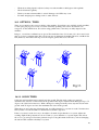
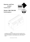
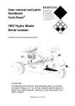
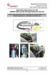
Operating and Parts
manual
Verti-Drain®
Model 7521
Serial number:
Translation of the original operating instructions
NOTE:
IN ORDER TO ENSURE THE SAFE USE AND TO ACHIEVE THE BEST
PERFORMANCE, IT IS ESSENTIAL THAT THIS OPERATING MANUAL
IS CAREFULLY READ BEFORE THE VERTI-DRAIN IS USED.
0948 English 911.120.461
FOREWORD
Congratulations on the purchase of your VERTI-DRAIN. To ensure the safe and lasting operations of
this VERTI-DRAIN you (and anyone using the machine) should read and understand this user’s
manual. A complete knowledge of the contents of the manual is necessary in order to ensure the safe
use of this machine.
The VERTI-DRAIN is not an independently operating machine. It is the responsibility of the user to
use the correct tractor. The user will also need to check the tractor / VERTI-DRAIN combination on
safety aspects, noise level, user instructions and risk analysis.
The VERTI-DRAIN is intended exclusively for grass fields or areas on which grass can grow.
On the following page, we will begin with the safety instructions. Every user must be familiar with
these instructions and must follow them carefully. Below you will find a registration card, which should
be returned to us so that we are able to process any future claims.
In this manual, many instructions are given which are stated in a number sequence. The user must
follow the instructions according to this sequence. If the * appears this refers to safety instructions. If
the @ is used, this refers to a tip and/ or note.
All information and technical specifications provided at the moment that this document is published
are the most recent ones. Design specifications may be changed without prior notice.
This document is a translation of the original operating instructions.
Upon request, the original operating instructions are available in Dutch.
GUARANTEE CONDITIONS
THIS VERTI-DRAIN PRODUCT IS DELIVERED TO THE CUSTOMER ACCOMPANIED BY A
GUARANTEE AGAINST DEFECTS IN THE MATERIALS USED. THIS GUARANTEE APPLIES
FOR A PERIOD OF 12 MONTHS AS OF THE DATE OF PURCHASE.
VERTI-DRAIN GUARANTEES ARE SUBJECTED TO THE "GENERAL CONDITIONS FOR
SUPPLY OF PLANT AND MACHINERY FOR EXPORT, NUMBER 188", WHICH ARE
PUBLISHED UNDER THE AUSPICES OF THE UNITED NATIONS ECONOMIC COMMISSION
FOR EUROPE.
REGISTRATION CARD
For your own record, copy the information from the registration card to the table hereunder.
Serial number of machine
Name of your distributor
Date of purchase
Any remarks
2
SAFETY INSTRUCTIONS.
1.
Always use the VERTI-DRAIN with the correct tractor as described in the
technical information
2.
The user is responsible for a safe Tractor/VERTI-DRAIN combination. The
combination must be tested for noise, safety, risk and easy usage. It is also necessary
to draw up user instructions.
3.
The VERTI-DRAIN is suited exclusively to grass fields.
4.
Every VERTI-DRAIN user must be fully informed of the information contained in
the user manual.
5.
Inspect the ground where the VERTI-DRAIN is to be applied. Remove loose
obstacles, avoid uneven ground.
6.
Never step off the tractor if the engine is still running.
7.
Ensure that other people are standing at least 4 mtr. (14' ) away from the
VERTI-DRAIN.
8.
Use appropriate clothing. Wear strong shoes with a steel inforced toe cap, long
trousers, tie up long hair. Do not have any loose pieces of clothing.
9.
Never try to force the VERTI-DRAIN, a situation which is visible in the partial
loosening of the front roller from the ground and unstable behavior of the
VERTI-DRAIN.
10.
Check the VERTI-DRAIN once a week to ensure there are no loose screws or nuts
and bolts.
11.
The VERTI-DRAIN may never be used without protection covers and safety
stickers.
12.
NEVER crawl underneath the VERTI-DRAIN. If you need to work underneath,
turn the VERTI-DRAIN on its front.
13.
Always switch off the engine and uncouple the power take off, before starting any
maintenance, adjustment or repair. Also block the VERTI-DRAIN against sinking and
block it against forward/backward movement or sliding.
14.
Use only the original VERTI-DRAIN spare parts/ tines in order to ensure the safe
operation of the machine.
15.
Never use the VERTI-DRAIN in the dark, in heavy rain, on frozen ground, stormy
conditions or on slopes greater than 20 degrees.
16.
Before operating the machine, also read the instructions and the maintenance
information for the power take off. This component has its own certification mark.
17.
Maintain a log book of repairs.
18.
If any modifications are carried out on the machine the CE certification mark will be
no longer valid. The User/Dealer himself must then have the machine re-certified.
3
CONTENTS.
Par.
Page
Foreword
2
Guarantee conditions
2
Registration card
2
Safety instruction
3
1.0
Technical specification
5
2.0
First setup, lifting machine from pallet
6
3.0
General controls
7
4.0
PTO
8
4.1
PTO length
8
4.2
Use of PTO
9
4.3
Slipclutch information and maintenance
9
5.0
Working depth adjustment
10
6.0
Tine angle adjustment
10
7.0
Groundspeed
11
8.0
Starting procedures
12
9.0
General usage of Verti-Drain
13
10.0
Transport of Verti-Drain
13
11.0
Uncoupling of the Verti-Drain
13
12.0
Problem analysis
14
13.0
Maintenance
15
14.0
EU-Declaration
15
15.0
Technical information
16
15.1
Torque settings
16
15.2
The crankshaft
17
15.2.1
Replacing the transmission oil seal
17
15.2.2
Replacing of a crank and crank bearing
17
15.2.3
Removing the crankshaft tension
17
Alignment of an element
18
Options, wheel kit
18
16.0.1
Mounting the wheelkit to the machine
18
16.0.2
Some guidelines for the wheel kit use
19
Options, tines
20
16.1.1
Solid tines
20
16.1.2
Hollow tines
21
16.1.3
Auxiliary spring kit
21
16.1.4
Rear roller extension kit
22
15.3
16.0
16.1
4
1.0 TECHNICAL SPECIFICATIONS
Model
7521
Working width
2.10 mtr (7’)
Working depth
Up to 400 mm (16”)
Tractor speed @ 500 rev’s at PTO
Hole spacing 65 mm (2-1/2”)
Up to 0.70 km/h (0.45 mph)
Hole spacing 130mm( 5”)
Up to 1.40 km/h (0.90 mph)
Hole spacing 195mm(7-1/2”)
Up to 2.10 km/h (1.35 mph)
PTO speed
Up to 500 rpm
Weight
1375 Kg (3025 lbs)
Hole spacing side-to-side
129 mm (5”) @ 24 mm (1”) holes
65 mm (2.5”)@ 12 mm (1/2”) holes
Hole spacing in driving direction
50 – 195 mm ( 2 - 7-1/2”)
Recommended tractor size
55 HP with lift capacity of minimum 1650 Kg
( 3600 lbs)
Capacity (maximum)
Spacing 65 mm (2-1/2”)
Up to 1470 sq.mtr (13400 sq ft)/ hour
Spacing 130mm (5 “)
Up to 2940 sq.mtr (26800 sq.ft)/ hour
Spacing 195mm (7-1/2”)
Up to 4410 sq.mtr (40200 sq.ft)/ hour
Shipping dimensions
2280 x 1000 x 1500 mm
(91”x 40”x 60”)
Maximum tine size
Solid 24 x 400 mm (1”x 16”)
Hollow 32 x 300 mm (1-1/4”x 12”)
Slip clutch setting PTO
Maximum 800 Nm. (7080 lb.inch.)
Three point linkage
3- point CAT 2
Transmission oil
Life time grease EP 00
Lubrication grease
EP 2
Standard items
Set solid tines 18x300 (3/4”x 12”)
Front and rear roller
3- shuttle gearbox
Toolbox with combi tool
PTO shaft
5
Fig.1.
2.0 FIRST SETUP, LIFTING MACHINE FROM PALLET
The machine stands vertically up on the pallet. To remove the pallet and get the machine horizontal on the
ground, handle as follows (see fig.1 ):
1. Open the rear cover
2. Connect a cable to lift point
* ensure the cable/crane/lift truck can lift minimum 4000 Kg.(9000 lbs).
3. Raise machine with pallet 50 mm (2")from the ground.
4. Remove pallet by sliding it over the bottom 3-point pins
* Do not crawl under the machine
5.Lower the machine gentle till 3-point connecting plates contact the ground.
6. Drop the machine further, enabling it to rotate on its front roller.
7. Gently lower the machine till it stands on the front and rear roller.
8. Connect the machine to a tractor.
* Use correct tractor; see specifications.
9. Lift the machine from the ground.
10. Remove the rear roller lock pins. Put pins in hole 4.
11. Lower the machine on the ground and adjust the angle of 90 degrees with top link
@ this angle is very important, see further.
12. Adjust tractor lower link stabilizers to limit sideways movement to about 100 mm (4”).
13. Fix tine angle adjustment lever to machine (separately packed with tines in box).
14. Assemble the tines. Use some grease on the shank.
15. PTO length, see 3.1
6
Fig.2.
5
9
2
3
8
4
6
16
7
11
10
15
14
12
13
1
17
18
3.0 GENERAL CONTROLS
In fig.2. some key details of the machine are shown, as follows:
1. Safety decall RA, before using machine read manual. Decall is located at the toolbox with
manuals and combi-tool.
2. Safety decall RB, Keep 4 mtr (14') distance to the machine
3. Safety decall RC, turn engine off when maintaining or repairing machine
* All decalls should be on the machine and understood all the time
4. Serial number of machine can be found inside
5. Spindle to adjust working depth.
6. Working depth indicator. Note the indication is related to maximum tine length.
7. Tine angle adjustment lever.
8. Knurled nuts for securing the rear access door of the VERTI-DRAIN.
* rear access door should always be closed and free of any damage.
9. Rubber stops for supporting the rear access door when opened.
10. Rear roller support guide.
11. Rear roller lock pin. Lock only when machine is stored or roller is raised from the ground
with hollow coring tines
12. Front roller support lock nuts.
13. Lower 3-point linkage pins. May be re-positioned and facing in or out.
14. PTO protection covers at the machine. Top one can be removed for maintenance.
15. PTO input shaft. Slipclutch should be assembled at this shaft.
16. Rear roller scraper, can be adjusted.
17. Protection plate rear roller support. Should be adjusted at 30 mm (1”) from the ground.
18. Front roller scraper, can be adjusted and be used for turf hold down fingers( option).
7
4.0 PTO
30°
The PTO is a very important item. It drives the machine from the tractor and ensures the safe
operations when correctly maintained and installed. The PTO shaft has its own CE certification. Read
the PTO shaft manual, which is connected to the shaft itself.
Max
30°
Max
A
B
150 m
m
L
(6") m
in
L standard = 33 mm 1.300"
L minimum= 31.5 mm 1.250"
Fig.3.
4.1 PTO LENGTH
The length of the PTO is very important. When too long, the transmission of the tractor and/or VERTI-DRAIN
may be damaged. When the overlap length of the tubes drops under 150 mm (6") anytime, the PTO may be
damaged.
* the length changes when the machine is raised or when another tractor is used.
To cut the standard PTO from new or for another tractor, work as follows (see fig. 3):
1. Measure the distance between tractor PTO shaft and VERTI-DRAIN PTO shaft from groove to
groove when machine is on the ground at correct angle and attached to the tractor.
2. Measure the length B of the PTO in its shortest position from lock pin to lock bolt.
3. Split PTO in two pieces and remove safety cover from each end
4. Both tubes and safety cover ends should be shortened: (B - A) + 75 mm (3").
5. Deburr all items, use some grease and put all parts together.
6. Assemble the slipclutch side of the PTO to the VERTI-DRAIN transmission.
* Torque for lock bolt should be 80 Nm (700 lb.in.) and checked every 40 hours
7. Connect other side to the tractor.
8. Check overlap of tubes.
* Never run machine with a damaged PTO safety cover. Replace it first.
8
4.2 USE OF PTO
For the correct use of the PTO, the following items need to be checked:
1. During work the angle of the joints may never exceed 30 degrees
2. The joints have to be in line all the time
3. The tube overlap should always be minimal 150 (6") mm
4. Never use the machine with a damaged PTO protection cover.
5. For greasing see par. 13.0 Maintenance.
4.3 SLIPCLUTCH INFORMATION AND MAINTENANCE
The slipclutch will protect your machine against breakages when correctly used and maintained. The following
items are important.
1. The spring length is standard set at 33.0 mm , 1.300".
2. When the slipclutch slips, the bolt/nuts may be tightened a quarter of a turn at a time, till the
minimum length of 31.5mm, 1.250" on the spring is reached. Any further compression will
overload the machine
@ If too tight the machine may break down in the end or unsafe situations may occur.
3. The slipclutch should be maintained every month. Work as follows;
- Remove the top PTO protection cover of the machine
- Loosen up all bolts/ nuts two turns.
- Run the machine in the field at very low rpm's
- If the clutch slips, stop after 10 seconds.
- If it doesn't slip, loosen bolts more or go to (annual) maintenance.
- When the slipclutch has slipped, tighten the bolts/nuts up to the point the slipclutch works fine.
* Do not tighten it to the previous setting right away.
4. Annual maintenance:
- remove PTO from machine.
- inspect PTO shaft parts. Damaged parts should be replaced.
- disassemble the slip clutch by removing all bolts/nuts that hold the springs
- the slipclutch should fall apart in pieces.
- lay down the pieces and inspect parts. If parts are damaged or worn, replace them.
- clean all mating surfaces.
- assemble all parts and tighten bolts/nuts till the springs are all set at 33.0 mm , 1.300".
- Grease both tubes and assemble both PTO parts to each other.
- Assemble the PTO and mount it to the machine.
- Re-adjust the springs of the slipclutch when necessary as previously described.
@ The slipclutch protects the machine only against peak loads, when correctly adjusted. A continuous
overload will damage the machine in the long run and is not protected by the slip clutch. Do not
overload your machine.
9
3
3
1
4
3
.2
560.00
2
1.
Fig.4.
Fig.5.
5.0 WORKING DEPTH ADJUSTMENT.
The working depth can be adjusted when the machine is lifted from the ground as follows, see fig. 4:
Unscrew nuts 1 at each side of the machine one turn. Screw spindle 3 in or out. Every revolution is 4 mm
(0.160"). The decall 2 at each side of the machine shows the actual depth. When the correct depth is reached,
tighten the nuts 1 at each side.
@ Never adjust one side more than 4 turns. Compensate the other side first before proceeding.
@ The adjustment can be done with a special tool in the machine tool box.
@ The value at the decalls is only true when 400 mm (16") long tine are used. When shorter
tines are used, deduct the length difference to the 400 mm (16") from the actual decall reading.
@ Clean and spray the spindle and nut with anti-sticking grease oil every 100 hours, to prevent dirt
sticking on the nut.
6.0 TINE ANGLE ADJUSTMENT.
The adjustment of the angle of all tine holders is centrally located at the right side of the machine, see fig.5..
Raise the machine above the ground, slacken the nuts 2 at each side of the machine and nuts 3 at the center of
the machine, one turn each.
Adjust the tine angle by rotating the lever 1. The angle-value can be read from the decall 4 next to the handle.
After the correct angle is set, tighten all nuts.
@ An angle of 90 degrees means almost no tine movement in the ground. This is required for hollow coring
tines and advised for thinner tines.
@ From 90 to 75 degrees means more "kick action". This is advised for solid tines, depending on ground
conditions, tine size and customer requirements.
@ The angle of 90 degrees means that the tines penetrate perpendicular into the ground. This is only true if the
machine is correctly set, see fig.1. If this isn't correct a push force F, see fig 5. is applied, which can seriously
damage the machine.
10
@ The length of the draw rod assembly should be 560.00 mm (22.050"), which can be set by the calibrating
shims, see the spare part page.
Combi Tool
D
Fig.6.
7.0 GROUNDSPEED.
The groundspeed determines the hole spacing D in the drive direction, see fig.6. The VERTI-DRAIN doesn't
need a creeper gear, however if the customer wants a close hole spacing, the groundspeed should be low
enough, which depends on the tractor.
The gearbox has standard three different gearsetting, resp 1,2 an 3. The higher the setting, the more rev's on the
crankshaft.
The input speed R on the PTO may be maximum 500 rpm. When stones or rocks are expected, the input speed
should be lowered.
With heavier tines, attachments or at maximum tine angle, the tineholders may start to float. Lower rpm's at
that time, before the tineholders start to turn upwards.
In Fig.6., a graph is drawn in which the relation between the groundspeed, the gear setting and the hole spacing
is given. If the tractor groundspeed is known at 500 rpm's of the PTO, the hole spacing can be determined at
different gearbox settings.
@ If the machine is not set correctly behind the tractor, see fig.1., different angles at the PTO may cause
vibration into the drive line of the VERTI-DRAIN. This vibration can hurt the machine and also the
performance of the holes in the ground.
@If the gear box setting is hard to shift, rotate the crankshaft a little till the shifting is possible. You can use
the “Combi-Tool”for easily rotating the crankshaft.
@ If the PTO shaft is incorrectly fitted (too long or too short), extra forces are applied to the input shaft of the
gearbox. Damage may occur.
* When the gearbox is shifted, shut off the tractor engine.
11
B
C
A
Fig.7.
8.0 STARTING PROCEDURES.
The starting procedure is VERY important. If the start up is not done as described hereunder, serious damage
to the machine may occur. Proceed as follows, see fig.7.:
1. Drive to the spot you want to start the operation.
2. Lower the machine, till the lowest tines are almost on the ground.
3. Set tractor engine at appr. 1200 rpm's
4. Put tractor in correct gear, and start moving forward (A)
5. Engage PTO at tractor (B)
6. DURING rolling forwards with the machine RUNNING, GENTLY lower the machine in the
ground (C), till front roller is tight on the ground.
7. Increase engine rpm's till the maximum value permitted.
At the end of a pass, quit the operation as follows:
1. Lower engine rpm's till about 1200.
2. Raise machine out of the ground.
3. As soon as all tines are out of the ground, disengage PTO.
4. Raise machine further, till the lowest tines are at least 120 mm (5") above the ground.
5. Move to the next spot and start again as described above.
@ It is absolutely necessary to proceed as described above. If the machine is put into the ground first,
without the PTO running, serious damage may occur.
@ The machine needs to be lowered GENTLY.
@ Be careful with driving backwards.
During work the front roller needs to be stable on the ground. If the machine starts to be unstable, change the
rpm's on the PTO. If this doesn't make any difference, adjust the working depth or change to other tines who
penetrate easier.
@ If nothing is done on the unstability of the machine, serious troubles may arise afterwards. The
machine is NOT protected against these circumstances on the long term.
@ Never drive backwards with the tines in or close to the ground.
12
@ NEVER drive backwards, when the lowest tines are less than 120 mm (5") above the ground.
If the tines get caught, serious damage will appear on the machine.
@ Do not use a hydraulic top link.
9.0 GENERAL USAGE OF VERTI-DRAIN.
The VERTI-DRAIN can only be used when the circumstances are right. Check the following items:
1. Are there any loose objects on the field. If so, these must be removed first.
2. Are there any slopes. The maximum slope for the VERTI-DRAIN is 20 degrees. Always operate
the VERTI-DRAIN from the top to the bottom of a slope.
3. Are there any pipes/wires/cables in the ground. If so, ascertain at what depth and set the working
depth at a maximum of 60% of the pipe etc. depth.
4. Are there any hard objects in the ground. If so, operate the VERTI-DRAIN with a very low PTO
speed, or adjust working depth.
5. Is there any danger of flying objects such as golf balls, which could distract the attention of the
driver ? If so, the VERTI-DRAIN can not be operated at that moment.
6. Is there any danger of subsidence or land/mud slides ? If so, the VERTI-DRAIN cannot be operated
on the field at that moment.
7. Is the ground frozen or very wet. Postpone operation till circumstances are better.
8. When ground is very compacted, use shorter thinner tines to penetrate, or adjust working depth.
10.0 TRANSPORT OF VERTI-DRAIN.
The user is responsible for the transport of the VERTI-DRAIN behind the tractor along the public
streets. Check on the national legislations. Across open ground a maximum speed of 12 km/h (8 mph)
applies. In view of the weight of the VERTI-DRAIN, a higher speed could be dangerous for the driver
and bystanders. The machine could also suffer damage due to jolt which can occur with higher speeds.
* At least 20% of the tractor weight should rest on the front axle when machine is lifted.
11.0 UNCOUPLING OF THE VERTI-DRAIN.
The machine can be disconnected from the tractor as follows:
1. Open the rear cover.
2. Rotate the crankshaft with the combi tool, until both central tineholders right/left from the gearbox,
are at their highest position.
3. Turn all other tineholders upwards against the stop
4. Lower the machine on a firm surface
5. Lock pin 3 into a corresponding hole, see fig.1.
6. Block the rear and front roller against rolling away.
7. Remove the top link.
8. Disconnect the PTO shaft from the tractor side
9. Disconnect the lower three point linkage arms.
* Shut down the tractor engine during walking around the VERTI-DRAIN.
13
12.0 PROBLEM ANALYSIS
Machine vibrates
Crankshaft rotates irregular
Machine not at 90 degrees.
PTO joint angles different.
PTO joints not in line.
Tough circumstances
Adjust working depth.
Use thinner/ shorter tines.
If dry, irrigate first.
Solid/ hollow tines
Wrong tine
are bending/ breaking
Change tine, use shorter one.
Use solids first before hollow
to break the soil.
Adjust working depth.
Tough circumstances
Use thinner/ shorter tines.
If dry, irrigate first.
Use solids first to break the soil.
Quick wearing
Front roller is not stable
Adjust tine angle setting
Wrong tines, too much resistance Change tine size.
on the ground
Adjust working depth.
Tough circumstances
Use other size tines.
Adjust working depth.
Irrigate first.
Do job not in one pass.
PTO breakages
Slipclutch slips often
Check setting.
Replace lining plates.
Clean clutch internally.
Tubes are cracking
PTO angles too wide.
Use the wheel kit.
PTO angles not the same.
Damage to draw rods
Bending/ breaking
Machine not at 90 degrees.
Central bar bent.
Bearing bushes worn.
Tines hit the ground with reversing.
Lift height not correct.
Damage to the turf
Oval holes
Soil too wet.
Change tine angle setting.
Reduce forward speed.
Turf damage
Adjust working depth.
Use thinner tines.
Tine not tight in tine
holder
Tough circumstances
Use other tines.
Grind flat area to tines.
Adjust the tine angle setting.
14
Crankshaft problems
Big end nuts slacken
Solve vibration, see vibration.
Crankshaft bearing collapsed.
Incorrect assembled after repair.
Remove, clean, use loctite
Rear roller shaking
Rear roller locked
Unlock,
Rear roller up with hollow coring Change speed and PTO rev’s,
Put roller free on the ground,
Tough circumstances
Change machine settings.
13.0 MAINTENANCE
Pre-Delivery-Inspection
Grease crankshaft bearings
8 shots each EP 2
Check bolts/ nuts
After first 20 hours
(new or repaired)
Connect the unit to a tractor
See instructions in this manual
Run unit for 5 min
Look and listen
Grease crankshaft bearings
4 shots each EP 2
Grease PTO and rollers
4 shots each EP 2
Check bolts/nuts
Look closely at machine
After every 100 hours
Grease crankshaft bearings
6 shots each EP 2
Grease PTO and rollers
4 shots each EP 2
Check bolts/ nuts
Look closely at machine
Grease spindles front roller
14.0 EU-DECLARATION
We, Redexim Utrechtseweg 127 3702 AC Zeist Holland, hereby declare fully on our authority that the
product:
VERTI-DRAIN 7521, WITH MACHINE NUMBER AS INDICATED ON THE MACHINE AND IN
THIS MANUAL,
to which this declaration relates is according to the stipulation of the 2006/42/EC directive for
machines.
Zeist, 01/10/09
A.C. Bos
Manager Operations & Logistics
Redexim Holland
15
15.0 TECHNICAL INFORMATION
45°
Generally speaking, this Verti-Drain is not a complicated machine. A couple of technical items will be
explained. If you still have questions, please contact your dealer, who is willing to assist you.
G 70 Nm.
Fig. 8.
15.1 TORQUE SETTINGS.
In fig.8., the torque settings of the most important bolts/nuts are given. For the ones the torque setting is not
mentioned, please be sure that they are tightened as a similar size bolt/nut would be tightened. If bolts/nuts are
working themselves loose, loctite may be applied.
Fig.9.
16
15.2 THE CRANKSHAFT.
In fig.9. the assembly of the crankshaft is given. Also look at the spare part page for a more clear view and
setup. On a 7521 the angle between the handles on the gearbox should be 45 degrees.
5.2.1 REPLACING THE TRANSMISSION OIL SEAL.
In fig.9. a top view of the crankshaft is given. To replace an oil seal at the transmission, handle as follows:
1. Loosen nuts II and IV, which may be tight because of the loctite. Some heat may help.
2. Remove big end V, after the big end pin VII is removed.
3. Remove cover III by unscrewing all the bolts/nuts.
4. Slide crank VI away from the gearbox using a hammer and hitting it slightly at the center, until big
end pin VII is free.
5. Rotate crank VI and slide big end IX from the big end pin VII.
6. Remove handle X after marking the position and removing nut VIII.
7. Pull oil seal out with a screw driver.
8. Clean area and assemble new oil seal.
9. Clean handle X and splined shaft and assemble the handle at the right position.
10. Before attaching nut/new lock plate, first fill the space under the locking plate (between the
splines and the handle) with liquid silicon paste.
11. Attach a new locking plate and nut VIII. Use loctite for the nut as well.
12. Assemble the other parts the same way as they have been removed.
13. If the crankshaft seems lumpish, see further 15.2.3.
15.2.2. REPLACEMENT OF A CRANK WITH BEARING.
Replacing a crank is necessary when it is cracked or when the big end nuts start to come loose on a regular
base. Either the crankbearing, the crankbearing fitting or the big end pin holes in the crank are damaged.
Replace the crank / bearing as soon as possible, to avoid any more damage to other parts, as follows:
1. Remove big end pin nuts IV (or II) from both big end pins connected to the crank.
2. Remove the big end pins, so that the big end can be swapped away. (Note; this will not happen with
the big end (pin) aside the gearbox.).
3. Remove the crank bearing covers III
4. Tap crank IV and bearing carefully side wards out of the frame by hitting the crank in the center
with a hammer.
5. Remove the bearing carefully from the crank.
6. After replacing the crank and/or bearing, replace the parts in the same sequence as they were
removed. Use loctite where indicated in fig.8.
7. If the crankshaft runs tight, see 15.2.3.
15.2.3 REMOVING THE CRANKSHAFT TENSION.
If parts have been replaced on the crankshaft, the crankshaft may seem running tight. This is because of
possible tension in the crankshaft parts. It is necessary to remove these, as follows ,see fig.9.:
1. Tap the center of the crank adjacent to the gearbox, alternately left and right.
2. Feel whether the crank moves and continue till the crank has nested.
3. Repeat this operation with the adjacent crank and continue this way till the crankshaft will operate
more smoothly.
17
@ After any repair on the crankshaft, the crankshaft nuts should be checked regularly, see 12.0
@ Don’t assemble the cranks at the wrong side of the machine. See the spare part pages for the right
part numbers.
15.3 ALIGNMENT OF AN ELEMENT.
In the event that an element is no longer in line with the adjacent elements, the alignment can be corrected as
follows (see fig.8.):
-
Slacken the four bolts/nuts A, that connect the crankshaft to the element.
-
Slacken the two bolts B, that fix the element to the main frame.
-
Try to align the element by moving it side wards, till it ligns up with the adjacent ones.
-
Start to tighten all bolts/nuts.
@ The element may be pushed out of line due to overload to the machine
@ When a crank is replaced, always re-align the element, so that no additional tension is created in
the total element assembly.
@ Any pre-tension in the element assembly will shorten the bearing life and may damage other parts
as well.
16.0 OPTIONS, WHEEL KIT.
The part number for a full transport kit for the 7521 is 9500110. This kit will be separately delivered and can
be mounted to a standard 3-point linkage machine. Generally speaking, a machine with wheel kit will reduce
the minimum horsepower required by 10 HP. It also can be taken off quickly, so the machine can be used either
way
16.0.1 MOUNTING THE WHEELKIT TO THE MACHINE.
G
H
F
E
D
C
A
B
AF
AG
AH
AI
I
J
K
AA
V
Z
Y
L
M
N
O
P Q
R S
T U
V
W
X
AB
AC
AD
AE
Fig.10.
18
Work as follows, see fig.10.:
1. Unpack all parts and lay them down.
2. Put machine horizontal on a hard floor with locked rear roller and in deepest working position.
3. Assemble pins Q in main frame each side and tighten nut inside.
4. Fix the arms O with pin U and distance washer W tight to machine with nut X..
5. Assemble the hydraulic cylinder M to pin Q and secure it with bolt/nut P/R. Use distance washer N.
6. Mount the rear beam B between both legs O using the 4 main bolt/nuts E/K and plate J. Before
tightening, assemble the hydraulic cylinder rod end with distance bush L with a similar bolt and nut. Do
not tighten the bolts/nuts yet.
7. Mount the rear wheels G with main shaft H (first put bush F at each bearing of the wheel) and lock
pin I to the leg O and rear beam B and secure it with bolt C and (spring) washer D.
8. Tighten all bolts/nuts E/K.
9.Reposition the standard bottom 3-point pins on the Verti-Drain to the front hole, both facing to the
right (standing behind machine).
10. Fix the draw bar AB to both repositioned 3-point pins and lock with linch pin.
11. Assemble the top link support AH at the standard bolt AG and lock it with the standard toplink pin.
Assemble it in the position drawn.
12. Assemble both top links AC between the top link support AH and the draw bar AB with pins AD.
Note one side of the top link is bent AI, which should be mounted at AH.
13. Fix the hoses S (long one) and T (short one) to the hydraulic cylinder and 90 degrees connector Y.
14. Mount the hydraulic pipes Z to the 90 degrees connector at one side and the T-connector at the
center side. Use clamps V to fix the hoses and the pipes to the Verti-Drain.
15. Connect the two hoses AF to the T-connecter. Note: since every country has different quick
connectors, no quick connectors are supplied. Use your own ones.
16. Check whether all bolts/nuts are tight.
17. Attach the tractor to the machine.
18. If the pin size of the tractor is different, bush AE can be exchanged.
19. Adjust the machine vertical with toplinks AC.
20. Raise the machine with hydraulic power of tractor and check hydraulic system.
21. Lower and raise machine 10 times, so that air can be removed from hydraulic system.
22. Assemble the longer PTO. Check the length according par. 4.1
16.0.2 SOME GUIDELINES FOR WHEEL KIT USE.
When the machine is used with a hydraulic wheel kit, be aware of the following:
-
The unit has no brakes. Highway use is limited to 25 km/h (15 mph)
-
Check the national legislation for highway use.
-
When the machine is in use, leave the wheels on the ground. A free floating hydraulic valve at the
tractor is necessary.
-
Tyre pressure should range from 1.0 – 2.0 bar (14-28 PSI). Note: when used at 1.0 bar the
maximum transport speed is 16 km/h (10 mph).
-
The maximum hydraulic system pressure is 175 bar (2400 PSI).
-
Never disconnect the hoses from tractor when machine is raised off the ground. Always ensure
that machine is tight on the ground with locked rear roller supports and relieved oil pressure,
before disconnecting the hoses. (see also par.11.0)
19
-
When the working depth is adjusted, always reset the machine at 90 degrees with toplinks.
-
Check bolts/nuts regularly.
-
Watch your turns when machine is raised. Damage to the PTO may occur
-
Do make straight passes during work, no turns allowed.
16.1 OPTIONS, TINES
Tines are essential for the correct working of the machine. Several tines are available for this machine,
see the spare part pages for a total overview. Generally speaking, tines can be divided into two
categories: Solids and Hollows. We advise using genuine tines, since they are fully adapted to the
machine.
In fig.11. several tine combinations are given. The tineholders have 5 x 12 mm (1/2”) holes and 2 x 24
mm (1”) holes for adapting tines.The lock bolt A may be tightened till 40 Nm (30 lbs.ft.) and B till 70
Nm (50 lbs.ft). If the tines still slip out of the adapter, grind a flat area to the tine.
A
A
A
B
B
Fig.11.
16.1.1 SOLID TINES.
Solid tines will break the hard compaction in the ground. The tine angle setting (see par.6.0)
determines the amount of “kick”action in the ground. If the angle is adjusted from 90 degrees up to 75
degrees, the “kick”action increases. With a 90 degrees setting we hardly create any tine motion in the
ground, with 75 degrees we have the maximum tine action in the ground.
When tines are new, they may disrupt the turf, specially when the root system is weak. Clean the tines
first by hand or use the machine for 10 minutes at another rough area.
If the rootsystem is weak, don’t try to break the soil much deeper than the root system. Adjust the
working depth till the penetration is about 75 mm (3”) more than the root system depth. This allows
the roots to grow deeper. Next time penetrate deeper. Using this method will safe you from damaging
the turf and will establish a healthy rootsystem.
20
We advise to use the solid tines with the sharp point facing to the front roller. This will create the best
tine action in the ground. However with a weak turf, it is worth using the tines with the sharp edge
facing the rear roller.
The rear roller may not be locked.
Use always tines with the same length and size. Replace a bent tine immediately. When this is not
done, the machine can be unstable. Don’t use any thicker/ longer tines as what is offered by us.
Shorter (worn) tines can be used in case shallower penetration is required. Note that the depth reading
on the decall is only correct when using the full maximum length tine
If oval holes are created, it means that we have a weak top layer and a hard pan underneath. Use
thinner tines or wait till the (wet) top layer has dried.
If topdressing needs to be applied, spread it first before using the Verti-Drain.
If the ground is hard to penetrate, irrigate first, use smaller diameter shorter tines or adjust working
depth. If not done, the machine will be hurt in the end.
With heavy tines, the tine holders may start to float. Reduce the PTO speed at that moment
immediately, because damage may occur when the tines hit the rear roller.
16.1.2 HOLLOW TINES.
With hollow tines, the soil can be exchanged. Different sizes are available, see the spare part manual.
The side outlet should face to the rear of the machine.
It is important that the tine angle is set a 90 degrees with hollow coring tines. The tine motion in the
ground is minimum and we create a nice clean hole. If the tine is still moving in the ground, the hollow
tine may break in the end.
If top dressing needs to be applied, use the Verti-Drain first, remove the cores and start spreading
sand.
If a lot of dirt is created during hollow coring, reduce your rpm’s or irrigate first. The dirt may wear
your machine
When the turf is damaged, use the solid tines first to establish a healthy root system first or adjust the
working depth.
The rear roller may be lifted and locked with the lock pin, so it doesn’t squash the cores. However
when the machine is a bit unstable and the rear roller starts to vibrate, it is better to keep the rear roller
on the ground.
If the hollow tines block, it means that the ground is (very) compacted and solid tines need to be used
first to break the ground. Irrigation may help as well, as adjusting the working depth.
16.1.3 AUXILIARY SPRING KIT
In some cases, people want more pre tension on the draw rod springs.
A complete spring kit per draw rod has the part number 211.752.004.. For a 7516 (H) you need 6 kits,
for the 7521 (H) 8 and for the 7526 (H) 10 kits.
Mounting instructions
The spring 1 should be exactly above the draw rod assembly 2, see Fig. This can be achieved by the
angle A of both clamps 3 and 4.
Start with assembling clamp 3 at a distance of 48 mm ( 2”) from the draw rod head end. This is
critical, otherwise the tineholder can’t be turned up anymore.
21
Next the other clamp 4 can be positioned at a maximum length of 280 mm ( 11”) away from clamp 3.
If the length is more ( measured when the draw rod is in its neutral position), damage to the springs
and other components may occur.
Be very careful in fitting the springs on the eye nuts (5/6), because the spring has to be stretched,
which can be dangerous.
@ It is important to adjust all springs at the same pre tension at a machine. The tension can be
reduced by reducing the length 280 mm. The spring can be taken out as well.
@ The tine holder can be turned upwards, when the assembly is done correctly. Check whether the
springs or eye nuts hit something after the installation.
@ With the auxiliary springs assembled, the capacity may increase, but we still have to be aware of
overspeeding the machine. Like with all other Verti-Drains with a rear roller, the tines may turn
towards the roller and hit the roller for different reasons.
@ When we apply too much spring force on the tines ( especially in combination with the 12 mm (
½”)), we may destroy the hole edge, since the spring is pulling hard at the moment the tines are
leaving the ground. Extra spring force is not advised for such applications.
22
16.1.4 REAR ROLLER EXTENSION KIT
The kit 211.752.002 can be mounted at the standard rear roller supports and moves the roller further
away from the moving parts inside the machine.
Since the rear roller is further away from the machine, special attention for shaking of the rear roller is
necessary under tough circumstances. If the shaking goes on for a longer while, the rear roller scraper
ends may break together with the rear roller bearings.
Assemble the kit the way it is drawn above. Tighten all bolts and nuts.
This kit can’t be used on 75 models with a wheel kit assembled ( the H models).
23