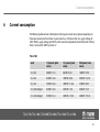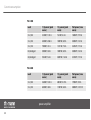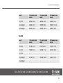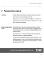
1
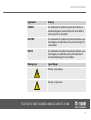
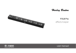
TSA 4-700, TSA 1400, TSA 2200,
TSA 4000, TSA 4-300, TSA 4-1300
power amplifier
user manual
Musikhaus Thomann e. K.
Treppendorf 30
96138 Burgebrach
Germany
Telephone: +49 (0) 9546 9223-0
E-mail: [email protected]
Internet: www.thomann.de
04.12.2014, ID: 218912, 218913, 218915, 287602, 325986, ... (V2)
Table of contents
Table of contents
1
General information.................................................................................................................................
1.1 Further information...........................................................................................................................
1.2 Notational conventions....................................................................................................................
1.3 Symbols and signal words...............................................................................................................
2
Safety notes.................................................................................................................................................. 8
3
Features....................................................................................................................................................... 13
4
Installation and starting up................................................................................................................ 14
5
Connections and operating elements........................................................................................... 15
6
Current consumption............................................................................................................................ 31
7
Technical specifications....................................................................................................................... 35
8
Plug and connection assignment.................................................................................................... 47
9
Cleaning....................................................................................................................................................... 50
10
Protecting the environment.............................................................................................................. 51
TSA 4-700, TSA 1400, TSA 2200,TSA 4000, TSA 4-300, TSA 4-1300
3
4
5
6
6
General information
1
General information
This manual contains important instructions for the safe operation of the unit. Read and follow
the safety instructions and all other instructions. Keep the manual for future reference. Make
sure that it is available to all those using the device. If you sell the unit please make sure that
the buyer also receives this manual.
Our products are subject to a process of continuous development. Thus, they are subject to
change.
power amplifier
4
General information
1.1 Further information
On our website (www.thomann.de) you will find lots of further information and details on the
following points:
Download
This manual is also available as PDF file for you to download.
Keyword search
Use the search function in the electronic version to find the topics of
interest for you quickly.
Online guides
Our online guides provide detailed information on technical basics
and terms.
Personal consultation For personal consultation please contact our technical hotline.
Service
If you have any problems with the device the
customer service will gladly assist you.
TSA 4-700, TSA 1400, TSA 2200,TSA 4000, TSA 4-300, TSA 4-1300
5
General information
1.2 Notational conventions
This manual uses the following notational conventions:
Letterings
The letterings for connectors and controls are marked by square brackets and italics.
Examples: [VOLUME] control, [Mono] button.
Cross-references
References to other locations in this manual are identified by an arrow and the specified page
number. In the electronic version of the manual, you can click the cross-reference to jump to
the specified location.
Example: See Ä ‘Cross-references’ on page 6.
1.3 Symbols and signal words
In this section you will find an overview of the meaning of symbols and signal words that are
used in this manual.
power amplifier
6
General information
Signal word
Meaning
DANGER!
This combination of symbol and signal word indicates an
immediate dangerous situation that will result in death or
serious injury if it is not avoided.
CAUTION!
This combination of symbol and signal word indicates a pos‐
sible dangerous situation that can result in minor injury if it
is not avoided.
NOTICE!
This combination of symbol and signal word indicates a pos‐
sible dangerous situation that can result in material and
environmental damage if it is not avoided.
Warning signs
Type of danger
Warning – high-voltage.
Warning – danger zone.
TSA 4-700, TSA 1400, TSA 2200,TSA 4000, TSA 4-300, TSA 4-1300
7
Safety notes
2
Safety notes
Intended use
This device amplifies electric audio frequency signals to operate passive speakers. Use the
device only as described in this user manual. Any other use or use under other operating con‐
ditions is considered to be improper and may result in personal injury or property damage. No
liability will be assumed for damages resulting from improper use.
This device may be used only by persons with sufficient physical, sensorial, and intellectual
abilities and having corresponding knowledge and experience. Other persons may use this
device only if they are supervised or instructed by a person who is responsible for their safety.
Safety
DANGER!
Danger for children
Ensure that plastic bags, packaging, etc. are disposed of properly and are not
within reach of babies and young children. Choking hazard!
Ensure that children do not detach any small parts (e.g. knobs or the like) from
the unit. They could swallow the pieces and choke!
Never let children unattended use electrical devices.
power amplifier
8
Safety notes
DANGER!
Electric shock caused by high voltages inside
Within the device there are areas where high voltages may be present. Never
remove any covers.
There are no user-serviceable parts inside.
DANGER!
Electric shock caused by short-circuit
Always use proper ready-made insulated mains cabling (power cord) with a pro‐
tective contact plug. Do not modify the mains cable or the plug. Failure to do so
could result in electric shock/death or fire. If in doubt, seek advice from a regis‐
tered electrician.
TSA 4-700, TSA 1400, TSA 2200,TSA 4000, TSA 4-300, TSA 4-1300
9
Safety notes
CAUTION!
Possible hearing damage
The device can produce volume levels that may cause temporary or permanent
hearing impairment. Over an extended period of time, even levels that seem to
be uncritical can cause hearing damage.
Decrease the volume level immediately if you experience ringing in your ears or
hearing impairment. If this is not possible, keep a greater distance or use suffi‐
cient ear protectors.
NOTICE!
Risk of fire
Do not cover the device nor any ventilation slots. Do not place the device near
any direct heat source. Keep the device away from naked flames.
power amplifier
10
Safety notes
NOTICE!
Operating conditions
This device has been designed for indoor use only. To prevent damage, never
expose the device to any liquid or moisture. Avoid direct sunlight, heavy dirt, and
strong vibrations.
NOTICE!
Power supply
Before connecting the device, ensure that the input voltage (AC outlet) matches
the voltage rating of the device and that the AC outlet is protected by a residual
current circuit breaker. Failure to do so could result in damage to the device and
possibly injure the user.
Unplug the device before electrical storms occur and when it is unused for long
periods of time to reduce the risk of electric shock or fire.
TSA 4-700, TSA 1400, TSA 2200,TSA 4000, TSA 4-300, TSA 4-1300
11
Safety notes
NOTICE!
Magnetic fields
The device generates strong magnetic fields that can interfere with the function
of poorly shielded devices. The strongest magnetic fields are directly above and
below the power amplifier. Therefore, never place sensitive devices such as preamplifiers, radio transmission systems, or tape decks directly above or below the
power amplifier. When installing the power amplifier into a rack, you should place
it in the lowest position, and further equipment such as pre-amplifiers in the
highest position.
power amplifier
12
Features
3
Features
Common features of all models described:
integrated switching power supply
XLR inputs
lockable NL4 output sockets
protective circuits
– audio limiter
– thermal protection
– short circuit protection
n 19" rack-mountable (2 RU)
n
n
n
n
Find device-specific features here Ä Chapter 5 ‘Connections and operating elements’ on page 15,
Ä Chapter 6 ‘Current consumption’ on page 31 and Ä Chapter 7 ‘Technical specifications’
on page 35.
TSA 4-700, TSA 1400, TSA 2200,TSA 4000, TSA 4-300, TSA 4-1300
13
Installation and starting up
4
Installation and starting up
Unpack and carefully check that there is no transportation damage before using the unit. Keep
the equipment packaging. To fully protect the device against vibration, dust and moisture
during transportation or storage use the original packaging or your own packaging material
suitable for transport or storage, respectively.
Establish all connections as long as the unit is switched off. Use the shortest possible highquality cables for all connections.
power amplifier
14
Connections and operating elements
5
Connections and operating elements
Front panel TSA 4-700
TSA 4-700, TSA 1400, TSA 2200,TSA 4000, TSA 4-300, TSA 4-1300
15
Connections and operating elements
1 [POWER]
Main switch to turn the device on and off.
2 LED indicators for [CH-A] … [CH-D]
These LEDs indicate that the unit is operational ([Power]), the input signal level ([Signal] / –20 / –15 / –10 / –5),
channel overload ([Clip]) and a fault condition ([Fault]).
3 [CH-A] … [CH-D]
Input gain controls for channels A to D.
The LED [Power] lights permanently during operation. The LEDs [Signal] / [–20] /
[–15] / [–10] / [–5] respond to the input signal. If any of these LEDs are lit without an
input signal is present disconnect the speakers from the amplifier and turn the input
gain controls of channels A to D down to minimum. If the LEDs will still light, the
device must be checked by an authorized service workshop.
power amplifier
16
Connections and operating elements
Rear panel TSA 4-700
TSA 4-700, TSA 1400, TSA 2200,TSA 4000, TSA 4-300, TSA 4-1300
17
Connections and operating elements
4 IEC chassis plug for the power supply.
5 [OUTPUT CH-A] … [OUTPUT CH-D]
Signal outputs, designed as lockable NL4 chassis socket to connect speakers.
6, 9, 10, 11 [INPUT CH-A] … [INPUT CH-D]
Signal input channels, designed as XLR socket pair (input / output) to loop the audio signal to other devices.
7 Push-button [Stereo | Bridge]
Switch for operating modes ‘Stereo’ (channels operate independently of each other) and ‘Bridge’ (two channels are
interconnected to form one channel with double output).
8 Push-button [Lift | Ground]
Use the Ground / Lift switch to separate the connection between the earth pin of the device and the unit's signal
ground to prevent ground loops:
n ‘Lift’ position (not pressed): no connection
n ‘Ground’ position (pressed): earth pin and signal ground are electrically connected
power amplifier
18
Connections and operating elements
Front panel TSA 1400, 2200,
4000
TSA 4-700, TSA 1400, TSA 2200,TSA 4000, TSA 4-300, TSA 4-1300
19
Connections and operating elements
1 [POWER]
Main switch to turn the device on and off.
2 LED indicators [CH-A], [CH-B]
These LEDs indicate that the unit is operational ([Power]), the input signal level ([Signal] / –20 / –15 / –10 / –5),
channel overload ([Clip]) and a fault condition ([Fault]).
3 [CH-A], [CH-B]
Input gain controls for channels A and B.
The LED [Power] lights permanently during operation. The LEDs [Signal] / [–20] /
[–15] / [–10] / [–5] respond to the input signal. If any of these LEDs are lit without an
input signal is present disconnect the speakers from the amplifier and turn the input
gain controls of channels A and B down to minimum. If the LEDs will still light, the
device must be checked by an authorized service workshop.
power amplifier
20
Connections and operating elements
Rear panel TSA 1400, 2200,
4000
TSA 4-700, TSA 1400, TSA 2200,TSA 4000, TSA 4-300, TSA 4-1300
21
Connections and operating elements
4 IEC chassis plug for the power supply.
5 [OUTPUT CH-A], [OUTPUT CH-B]
Signal outputs, designed as lockable NL4 chassis socket to connect speakers.
6, 9 [INPUT CH-A], [INPUT CH-B]
Signal input channels, designed as XLR socket pair (input / output) to loop the audio signal to other devices.
7 Push-button [Stereo | Bridge]
Switch for operating modes ‘Stereo’ (channels operate independently of each other) and ‘Bridge’ (two channels are
interconnected to form one channel with double output).
8 Push-button [Lift | Ground]
Use the Ground / Lift switch to separate the connection between the earth pin of the device and the unit's signal
ground to prevent ground loops:
n ‘Lift’ position (not pressed): no connection
n ‘Ground’ position (pressed): earth pin and signal ground are electrically connected
power amplifier
22
Connections and operating elements
Front panel TSA 4-300
TSA 4-700, TSA 1400, TSA 2200,TSA 4000, TSA 4-300, TSA 4-1300
23
Connections and operating elements
1 [POWER]
Main switch to turn the device on and off.
2 LED indicators [CH-A] … [CH-D]
These LEDs indicate that the unit is operational ([Power]), the input signal level ([Signal] / –20 / –15 / –10 / –5),
channel overload ([Clip]) and a fault condition ([Fault]).
3 [CH-A] … [CH-D]
Input gain controls for channels A to D.
The LED [Power] lights permanently during operation. The LEDs [Signal] / [–20] /
[–15] / [–10] / [–5] respond to the input signal. If any of these LEDs are lit without an
input signal is present disconnect the speakers from the amplifier and turn the input
gain controls of channels A to D down to minimum. If the LEDs will still light, the
device must be checked by an authorized service workshop.
power amplifier
24
Connections and operating elements
Front panel TSA 4-1300
TSA 4-700, TSA 1400, TSA 2200,TSA 4000, TSA 4-300, TSA 4-1300
25
Connections and operating elements
1 [POWER]
Main switch to turn the device on and off.
2 LED indicators [CH-A] … [CH-D]
These LEDs indicate that the unit is operational ([Power]), the input signal level ([Signal] / –20 / –15 / –10 / –5),
channel overload ([Clip]) and a fault condition ([Fault]).
3 [CH-A] … [CH-D]
Input gain controls for channels A to D.
The LED [Power] lights permanently during operation. The LEDs [Signal] / [–20] /
[–15] / [–10] / [–5] respond to the input signal. If any of these LEDs are lit without an
input signal is present disconnect the speakers from the amplifier and turn the input
gain controls of channels A to D down to minimum. If the LEDs will still light, the
device must be checked by an authorized service workshop.
power amplifier
26
Connections and operating elements
Rear panel TSA 4-300,
TSA 4-1300
TSA 4-700, TSA 1400, TSA 2200,TSA 4000, TSA 4-300, TSA 4-1300
27
Connections and operating elements
4 IEC chassis plug for the power supply.
5 [RESET]
Push-button to reset the unit, for example, after the built-in automatic fuse has tripped.
6 [OUTPUT CH-A] … [OUTPUT CH-D]
Signal outputs, designed as lockable NL4 chassis socket to connect speakers.
7 [INPUT 1] … [INPUT 4]
XLR signal input sockets.
8 [A]
Slide switch; determines how the input signals 1 and 2 are processed. In the upper switch position, the signals are fed
separately to the power amps. In the lower switch position, the signals are added and fed as a mono sum signal to
the power amps. The connection of the power amps is set by the push-button (11).
9 [B]
Slide switch; determines how the input signals 2 and 3 are processed. In the upper switch position, the signals are fed
separately to the power amps. In the lower switch position, the signals are added and fed as a mono sum signal to
the power amps.
power amplifier
28
Connections and operating elements
10 [C]
Slide switch; determines how the input signals 3 and 4 are processed. In the upper switch position, the signals are fed
separately to the power amps. In the lower switch position, the signals are added and fed as a mono sum signal to
the power amps. The connection of the power amps is set by the push button (13).
11 Push-button for switching the operating mode of the power amps for the output channels A and B.
n Push-button not pressed: Input signals 1 and 2 (connection depends on the position of switch [A] (8)) are being
amplified in ‘stereo’ mode and separately fed to outputs A and B. The volume for output A and output B can be
controlled separately with the controls for channel A or B (3). Wiring of the NL4 output sockets: Plus terminal =
1+, minus terminal = 1–.
n Push-button is pressed: Both power amps operate in ‘Bridge’ mode like one power amplifier with double output
power. Input signals 1 and 2 (connection depends on the position of switch [A] (8)) are being amplified. The
output signal is present only at output A, the volume is controlled by the control for channel A (3). Wiring of the
NL4 output sockets: Plus terminal = 1+, minus terminal = 2+.
TSA 4-700, TSA 1400, TSA 2200,TSA 4000, TSA 4-300, TSA 4-1300
29
Connections and operating elements
12 The input sensitivity at which the amplifier is delivering its full rated power, can be set with this push-button
between 0.775 VRMS (not pressed) and 1.4 VRMS (pressed).
13 Push-button for switching the operating mode of the power amps for the output channels C and D.
n Push-button not pressed: Input signals 3 and 4 (connection depends on the position of switch [C] (10)) are being
amplified in ‘stereo’ mode and separately fed to outputs C and D. The volume for output C and output D can be
controlled separately with the controls for channel C or D (3). Wiring of the NL4 output sockets: Plus terminal =
1+, minus terminal = 1–.
n Push-button is pushed: Both power amps operate in ‘Bridge’ mode like one power amplifier with double output
power. Input signals 3 and 4 (connection depends on the position of switch [C] (8)) are being amplified. The
output signal is present only at output C, the volume is controlled by the control for channel C (3). Wiring of the
NL4 output sockets: Plus terminal = 1+, minus terminal = 2+.
power amplifier
30
Current consumption
6
Current consumption
The following table contains information on the typical current consumption depending on
the output power level (root mean square value ARMS). All values refer to a supply voltage of
220 V. With a supply voltage of 230 V the data must be multiplied by factor 0.96, with 120 V by
factor 1,83 and with 100 V by factor 2.2.
TSA 4-700
Load
1/8 power (pink
noise)
1/3 power (pink
noise)
Full power (sine
wave)
(4 ×) 8 Ω
400 W / 3.1 A
860 W / 5.8 A
1400 W / 9.5 A
(4 ×) 4 Ω
650 W / 4.4 A
1500 W / 9.8 A
2450 W / 15.4 A
(4 ×) 2 Ω
950 W / 6.4 A
1800 W / 11.6 A
3100 W / 20 A
(2 ×) 8 Ω, bridged
620 W / 4.3 A
2450 W / 15 A
2450 W / 15 A
(2 ×) 4 Ω, bridged
870 W / 6.1 A
3300 W / 19.5 A
3300 W / 19.5 A
TSA 4-700, TSA 1400, TSA 2200,TSA 4000, TSA 4-300, TSA 4-1300
31
Current consumption
TSA 1400
Load
1/8 power (pink
noise)
1/3 power (pink
noise)
Full power (sine
wave)
(2 ×) 8 Ω
330 W / 1.93 A
734 W / 4.4 A
1400 W / 7.74 A
(2 ×) 4 Ω
480 W / 2.86 A
1200 W / 6.9 A
2300 W / 12.2 A
(2 ×) 2 Ω
700 W / 4.1 A
1313 W / 7.2 A
3345 W / 17.3 A
8 Ω, bridged
500 W / 3.0 A
1200 W / 6.9 A
2300 W / 12.4 A
4 Ω, bridged
984 W / 5.4 A
2690 W / 14.2 A
3310 W / 17.2 A
Load
1/8 power (pink
noise)
1/3 power (pink
noise)
Full power (sine
wave)
(2 ×) 8 Ω
260 W / 1.69 A
400 W / 2.73 A
1700 W / 9.5 A
(2 ×) 4 Ω
680 W / 4.0 A
1180 W / 6.5 A
2800 W / 14.97 A
TSA 2200
power amplifier
32
Current consumption
Load
1/8 power (pink
noise)
1/3 power (pink
noise)
Full power (sine
wave)
(2 ×) 2 Ω
850 W / 5.0 A
1800 W / 9.8 A
4200 W / 21 A
8 Ω, bridged
680 W / 4.1 A
1200 W / 6.8 A
2850 W / 15.2 A
4 Ω, bridged
820 W / 4.5 A
1900 W / 10.1 A
4600 W / 23 A
Load
1/8 power (pink
noise)
1/3 power (pink
noise)
Full power (sine
wave)
(2 ×) 8 Ω
475 W / 3.7 A
974 W / 6.8 A
2732 W / 17 A
(2 ×) 4 Ω
708 W / 5.1 A
1640 W / 11 A
4018 W / 26 A
(2 ×) 2 Ω
–
–
–
8 Ω, bridged
677 W / 5 A
1520 W / 10.2 A
4346 W / 27 A
4 Ω, bridged
–
–
–
TSA 4000
TSA 4-700, TSA 1400, TSA 2200,TSA 4000, TSA 4-300, TSA 4-1300
33
Current consumption
TSA4-300
Load
1/8 power (pink
noise)
1/3 power (pink
noise)
Full power (sine
wave)
(4 ×) 8 Ω
420 W / 3.2 A
1050 W / 7.5 A
1960 W / 13.6 A
(4 ×) 4 Ω
700 W / 5.2 A
1810 W / 12.5 A
2250 W / 21.7 A
2 ×8 Ω, bridged
706 W / 5.6 A
1847 W / 13.1 A
3438 W / 22.8 A
Load
1/8 power (pink
noise)
1/3 power (pink
noise)
Full power (sine
wave)
(4 ×) 8 Ω
1050 W / 7.5 A
2920 W / 18.7 A
6503 W / 39.4 A
(4 ×) 4 Ω
1580 W / 10.7 A
4230 W / 25.8 A
9410 W / 53 A
2 ×8 Ω, bridged
1631 W / 11.8 A
4450 W / 28.7 A
9020 W / 52.4 A
TSA4-1300
power amplifier
34
Technical specifications
7
Technical specifications
TSA 4-700
Load impedance
8W
4W
2W
Rated output power (THD ≤1 %, 1 kHz)
4 × 490 W
4 × 810 W
4 × 930 W
Max. output power ‘bridged’ (THD ≤1 %, 1 kHz)
2 × 1600 W
2 × 1800 W
–
Max. voltage swing (RMS) (THD ≤1 %, 1 kHz)
62.6 V
Slew rate (1 kHz)
38 V/ms
THD
< 0.1 %
IMD-SMPTE (60 Hz, 7 kHz)
< 0.1 %
DIM 30 (3.15 kHz, 15 kHz)
< 0.1 %
Crosstalk (ref. 1 kHz, 10 % rated power)
> 70 dB
Frequency response (ref. 1 kHz)
20 Hz … 20 kHz (0 – 2 dB)
TSA 4-700, TSA 1400, TSA 2200,TSA 4000, TSA 4-300, TSA 4-1300
35
Technical specifications
Input impedance (20 Hz - 20 kHz, balanced)
20 kW (balanced)
10 kW (unbalanced)
Input sensitivity (rated power output, 1 kHz)
1V
Damping factor (100 Hz / 1 kHz, 8 W)
> 400
Voltage amplification
38,4 dB
Signal-to-noise ratio
105 dB (A-weighted)
Protective circuits
Temperature, short circuit, limiter
Cooling
front to rear
Operating supply voltage
AC 230 V
Power consumption
see Ä Chapter 6 ‘Current consumption’ on page 31
Dimensions (W × H × D)
488 mm × 97 mm × 370 mm
Weight
10.7 kg
, 50/60 Hz
power amplifier
36
Technical specifications
TSA 1400
Load impedance
8W
4W
2W
Rated output power (THD ≤1 %, 1 kHz)
2 × 450 W
2 × 670 W
2 × 800 W
Max. output power ‘bridged’ (THD ≤1 %, 1 kHz)
1 × 1380 W
1 × 1600 W
–
Max. voltage swing (RMS) (THD ≤1 %, 1 kHz)
60 V
Slew rate (1 kHz)
35 V/ms
THD
< 0.1 %
IMD-SMPTE (60 Hz, 7 kHz)
< 0.1 %
DIM 30 (3.15 kHz, 15 kHz)
< 0.1 %
Crosstalk (ref. 1 kHz, 10 % rated power)
> 70 dB
Frequency response (ref. 1 kHz)
20 Hz … 20 kHz (0 – 2 dB)
TSA 4-700, TSA 1400, TSA 2200,TSA 4000, TSA 4-300, TSA 4-1300
37
Technical specifications
Input impedance (20 Hz - 20 kHz, balanced)
20 kW (balanced)
10 kW (unbalanced)
Input sensitivity (rated power output 1 kHz)
1V
Damping factor (100 Hz / 1 kHz, 8 W)
> 400
Voltage amplification
38,3 dB
Signal-to-noise ratio
105 dB (A-weighted)
Protective circuits
Temperature, short circuit, limiter
Cooling
front to rear
Operating supply voltage
AC 230 V
Power consumption
see Ä Chapter 6 ‘Current consumption’ on page 31
Dimensions (W × H × D)
484 mm × 97 mm × 370 mm
Weight
10.6 kg
, 50/60 Hz
power amplifier
38
Technical specifications
TSA 2200
Load impedance
8W
4W
2W
Rated output power (THD ≤1 %, 1 kHz)
2 × 590 W
2 × 910 W
2 × 1200 W
Max. output power ‘bridged’ (THD ≤1 %, 1 kHz)
1 × 1800 W
1 × 2400 W
–
Max. voltage swing (RMS) (THD ≤1 %, 1 kHz)
68.7 V
Slew rate (1 kHz)
41 V/ms
THD
< 0.1 %
IMD-SMPTE (60 Hz, 7 kHz)
< 0.1 %
DIM 30 (3.15 kHz, 15 kHz)
< 0.1 %
Crosstalk (ref. 1 kHz, 10 % rated power)
> 70 dB
Frequency response (ref. 1 kHz)
20 Hz … 20 kHz (0 – 2 dB)
TSA 4-700, TSA 1400, TSA 2200,TSA 4000, TSA 4-300, TSA 4-1300
39
Technical specifications
Input impedance (20 Hz - 20 kHz, balanced)
20 kW (balanced)
10 kW (unbalanced)
Input sensitivity (rated power output 1 kHz)
1V
Damping factor (100 Hz / 1 kHz, 8 W)
> 400
Voltage amplification
39,8 dB
Signal-to-noise ratio
105 dB (A-weighted)
Protective circuits
Temperature, short circuit, limiter
Cooling
front to rear
Operating supply voltage
AC 230 V
Power consumption
see Ä Chapter 6 ‘Current consumption’ on page 31
Dimensions (W × H × D)
485 mm × 97 mm × 370 mm
Weight
10.4 kg
, 50/60 Hz
power amplifier
40
Technical specifications
TSA 4-300
Load impedance
8Ω
4Ω
Rated output power (THD ≤1 %, 1 kHz)
4 × 350 W
4 × 550
Max. output power ‘bridged’ (THD ≤ 1 %, 1 kHz)
2 × 1000 W
–
THD
< 0.5 %
IMD-SMPTE (60 Hz, 7 kHz)
≤ 0.35 %
Crosstalk (at 1 kHz)
–75 dB
(at 20 kHz)
–58 dB
Frequency response (1 W)
20 Hz … 20 kHz (0 – 1 dB)
Input impedance
20 kΩ (balanced)
10 kΩ (unbalanced)
Input sensitivity (rated power output 1 kHz)
0.775 V / 1.4 V, (switchable)
Damping factor (10 Hz / 400 Hz, 8 W)
> 200
TSA 4-700, TSA 1400, TSA 2200,TSA 4000, TSA 4-300, TSA 4-1300
41
Technical specifications
Voltage amplification
35.3 dB
Signal-to-noise ratio
> 100 dB (A-weighted)
Protection circuits against
short circuit, missing load, cracking when turning on and off, radio
interference
Cooling
Internal heat dissipation with forced ventilation through con‐
trolled fan, overheating protection
Ventilation
front to rear
Operating supply voltage
AC 230 V
Power consumption
see Ä Chapter 6 ‘Current consumption’ on page 31
Dimensions (W × H × D)
482 mm × 88 mm × 227 mm
Weight
7.5 kg
power amplifier
42
, 50/60 Hz
Technical specifications
TSA 4-1300
Load impedance
8Ω
4Ω
Rated output power (THD ≤1 %, 1 kHz)
4 × 1220 W
4 × 1670
Max. output power ‘bridged’ (THD ≤1 %, 1 kHz)
2 × 4000 W
–
THD
< 0.5 %
IMD-SMPTE (60 Hz, 7 kHz)
≤ 0.35 %
Crosstalk (at 1 kHz)
–75 dB
(at 20 kHz)
–58 dB
Frequency response (1 W)
20 Hz … 20 kHz (0 – 1 dB)
Input impedance
20 kΩ (balanced)
10 kΩ (unbalanced)
Input sensitivity (rated power output 1 kHz)
0.775 V / 1.4 V, (switchable)
Damping factor (10 Hz / 400 Hz, 8 W)
> 200
TSA 4-700, TSA 1400, TSA 2200,TSA 4000, TSA 4-300, TSA 4-1300
43
Technical specifications
Voltage amplification
37.8 dB
Signal-to-noise ratio
> 100 dB (A-weighted)
Protection circuits against
short circuit, missing load, cracking when turning on and off, radio
interference
Cooling
Internal heat dissipation with forced ventilation through con‐
trolled fan, overheating protection
Ventilation
front to rear
Operating supply voltage
AC 230 V
Power consumption
see Ä Chapter 6 ‘Current consumption’ on page 31
Dimensions (W × H × D)
482 mm × 88 mm × 380 mm
Weight
12.5 kg
power amplifier
44
, 50/60 Hz
Technical specifications
TSA 4000
Load impedance
8W
4W
2W
Nominal power output (THD ≤1 %, 1 kHz)
2 × 1000 W
2 × 1500
–
Max. power output, bridged mode
(THD ≤1 %, 1 kHz)
1 × 2865 W
–
–
Max. voltage increase (RMS) (THD ≤1 %, 1 kHz)
89 V
Slew rate (1 kHz)
50 V/ms
Total harmonic distortion (THD)
< 0,1 %
IMD-SMPTE (60 Hz, 7 kHz)
< 0,35 %
DIM 30 (3.15 kHz, 15 kHz)
< 0,35 %
Crosstalk (at 1 kHz, 10 % nominal power)
< –80 dB
Frequency response (at 1 kHz)
20 Hz … 20 kHz (0 – 2 dB)
TSA 4-700, TSA 1400, TSA 2200,TSA 4000, TSA 4-300, TSA 4-1300
45
Technical specifications
Input impedance (20 Hz – 20 kHz, balanced)
20 kW (balanced)
10 kW (unbalanced)
Input sensitivity (nominal power output, 1 kHz)
1V
Damping factor (100 Hz / 1 kHz, 8 W)
> 450
Voltage amplification
37 dB
Signal-to-noise ratio (SNR)
106 dB (A-weighted)
Protective circuits
Thermal, short circuit, limiter
Cooling
from front to back
Mains power supply
230 V
Power consumption
see Ä Chapter 6 ‘Current consumption’ on page 31
Dimensions (W × H × D)
483 × 88 × 420 mm (19.02 × 3.46 × 1.53 inches)
Weight
12 kg (26.5 lbs)
(AC), 50/60 Hz
power amplifier
46
Plug and connection assignment
8
Plug and connection assignment
Introduction
This chapter will help you select the right cables and plugs to connect your valuable equip‐
ment in such a way that a perfect sound experience is ensured.
Please note these advices, because especially in ‘Sound & Light’ caution is indicated: Even if a
plug fits into the socket, an incorrect connection may result in a destroyed power amp, a short
circuit or ‘just’ in poor transmission quality!
Balanced and unbalanced trans‐
mission
Unbalanced transmission is mainly used in semi-professional environment and in hifi use.
Instrument cables with two conductors (one core plus shielding) are typical representatives of
the unbalanced transmission. One conductor is ground and shielding while the signal is trans‐
mitted through the core.
Unbalanced transmission is susceptible to electromagnetic interference, especially at low
levels, such as microphone signals and when using long cables.
In a professional environment, therefore, the balanced transmission is preferred, because this
enables an undisturbed transmission of signals over long distances. In addition to the conduc‐
tors ‘Ground’ and ‘Signal’, in a balanced transmission a second core is added. This also transfers
the signal, but phase-shifted by 180°.
TSA 4-700, TSA 1400, TSA 2200,TSA 4000, TSA 4-300, TSA 4-1300
47
Plug and connection assignment
Since the interference affects both cores equally, by subtracting the phase-shifted signals, the
interfering signal is completely neutralized. The result is a pure signal without any noise inter‐
ference.
XLR plug (balanced)
1
Ground, shielding
2
Signal (in phase, +)
3
Signal (out of phase, –)
1
Ground, shielding
2
Signal
3
Bridged to pin 1
XLR plug (unbalanced)
power amplifier
48
Plug and connection assignment
NL4 mounting connectors
1, +
Signal 1 (in phase)
1, –
Signal 1 (180 degree phase shift)
2, +
Signal 2 (in phase)
2, –
Signal 2 (180 degree phase shift)
TSA 4-700, TSA 1400, TSA 2200,TSA 4000, TSA 4-300, TSA 4-1300
49
Cleaning
9
Cleaning
Fan grids
The fan grids of the device must be cleaned on a regular basis to remove dust and dirt. Before
cleaning, switch off the device and disconnect AC-powered devices from the mains. Use a lintfree damp cloth for cleaning. Never use solvents or alcohol for cleaning.
power amplifier
50
Protecting the environment
10
Protecting the environment
Disposal of the packaging mate‐
rial
For the transport and protective packaging, environmentally friendly materials have been
chosen that can be supplied to normal recycling.
Ensure that plastic bags, packaging, etc. are properly disposed of.
Do not just dispose of these materials with your normal household waste, but make sure that
they are collected for recycling. Please follow the notes and markings on the packaging.
Disposal of your old device
This product is subject to the European Waste Electrical and Electronic Equipment Directive
(WEEE). Do not dispose with your normal household waste.
Dispose of this device through an approved waste disposal firm or through your local waste
facility. When discarding the device, comply with the rules and regulations that apply in your
country. If in doubt, consult your local waste disposal facility.
TSA 4-700, TSA 1400, TSA 2200,TSA 4000, TSA 4-300, TSA 4-1300
51
Notes
power amplifier
52
Notes
TSA 4-700, TSA 1400, TSA 2200,TSA 4000, TSA 4-300, TSA 4-1300
53
Notes
power amplifier
54
Musikhaus Thomann e.K. · Treppendorf 30 · 96138 Burgebrach · Germany · www.thomann.de