1
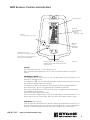
8873 Pathfinder
v3
Locator User Manual
Manual Part # 030-00100-00 Rev A
Table of Contents
General Information
Introduction . . . . . . . . . . . . . . . . . . . . . . . . . . . . . . . . . . . . . . . . . . . . . . . . 2
Prepare for Use . . . . . . . . . . . . . . . . . . . . . . . . . . . . . . . . . . . . . . . . . . . . . 2
Receiver Operation . . . . . . . . . . . . . . . . . . . . . . . . . . . . . . . . . . . . . . . 4-5
Absolute Signal Strength . . . . . . . . . . . . . . . . . . . . . . . . . . . . . . . . . . . . .
Gain Change Indication . . . . . . . . . . . . . . . . . . . . . . . . . . . . . . . . . . . . .
Passive Locating . . . . . . . . . . . . . . . . . . . . . . . . . . . . . . . . . . . . . . . . . . . .
Push Button Digital Depth . . . . . . . . . . . . . . . . . . . . . . . . . . . . . . . . . . . .
5
5
5
5
Transmitter Operation . . . . . . . . . . . . . . . . . . . . . . . . . . . . . . . . . . . . . . . 7
Frequency . . . . . . . . . . . . . . . . . . . . . . . . . . . . . . . . . . . . . . . . . . . . . . . . .
Loading . . . . . . . . . . . . . . . . . . . . . . . . . . . . . . . . . . . . . . . . . . . . . . . . . . .
Output Level Control . . . . . . . . . . . . . . . . . . . . . . . . . . . . . . . . . . . . . . . .
Low Battery . . . . . . . . . . . . . . . . . . . . . . . . . . . . . . . . . . . . . . . . . . . . . . . .
7
7
7
7
Line Locating
Signal Application Direct Connection . . . . . . . . . . . . . . . . . . . . . . . . . . 7
Signal Application Coupler Induction . . . . . . . . . . . . . . . . . . . . . . . . . . 7
Signal Application Transmitter Induction . . . . . . . . . . . . . . . . . . . . . . . . 8
Locating Buried Conductors . . . . . . . . . . . . . . . . . . . . . . . . . . . . . . . . . 10
Sonde Locating
Locating the Sonde . . . . . . . . . . . . . . . . . . . . . . . . . . . . . . . . . . . . . 11-13
Sonde Depth . . . . . . . . . . . . . . . . . . . . . . . . . . . . . . . . . . . . . . . . . . . . . . 13
Specifications . . . . . . . . . . . . . . . . . . . . . . . . . . . . . . . . . . . . . . . . . . 14-15
Factory Service . . . . . . . . . . . . . . . . . . . . . . . . . . . . . . . . . . . . . . . . . . . . 16
Warranty . . . . . . . . . . . . . . . . . . . . . . . . . . . . . . . . . . . . . . . . . . . . . . . . . . 16
800.851.7347
www.rycominstruments.com
1
Introduction Congratulations on the purchase of your new 8873 Pathfinder Locator. The 8873
Locator is specially designed to detect sondes and camera systems, and the unit
is capable of detecting buried power cables, CATV cables, gas and water pipes,
sewer lines, telephone cables, fiber optic cables with sheath.
For Sonde locating & camera head locating a signal is generated by the sonde or
camera head and the receiver detects the signal giving the user proximity cue to
determine its location.
The Transmitter emits a signal that is conducted or coupled to a conductors. The
Receiver detects the signal. You can locate the relative position of the buried
conductor by following the tracing signal.
! WARNING
Electric shock hazard:
• Tool is designed to detect electromagnetic field emitted from Camera Sondes
and buried metallic utilities. There are buried cables, pipes, and utilities this
instrument CANNOT detect.
• LOCATING is not an exact science. The only certain way to be sure of the existence, location, or depth of buried utilities is to carefully expose (dig up) the
utility.
• De-energize any circuits in or around the work area.
• Do not expose tool to rain or moisture.
• Use tool only for intended purpose as described in this manual
Failure to observe these warnings could result in severe injury or death.
DISCLAIMER OF LIABILITY
RYCOM INSTRUMENTS, INC SHALL NOT BE LIABLE TO DISTRIBUTOR, RESELLER, OR ANY
OTHER PERSON FOR ANY INCIDENTAL, INDIRECT, SPECIAL, EXEMPLARY OR CONSEQUENTIAL DAMAGES, OR INJURY OF ANY TYPE WHATSOEVER, AND CAUSED DIRECTLY OR INDIRECTLY BY PRODUCTS SOLD OR SUPPLIED BY RYCOM INSTRUMENTS, INC.
Part Numbers
8873 Pathfinder Locator
Receiver
Transmitter (C-Cell)
User’s Manual
4" Coupler (Optional)
Headset (Optional)
Prepare for Use
Unpack your new 8873 Locator . Make sure there is no shipping damage and all
the parts are included.
Locate the battery compartment on the back of the “head” of the Receiver
& Transmitter. Open the compartment using a phillips screwdriver. Install the
six Duracell® “C” batteries as marked in the Receiver and eight "C" cells in the
Transmitter.
Note: For longer battery life and reliable operation under adverse conditions,
use only Duracell® alkaline batteries.
800.851.7347
www.rycominstruments.com
2
Changing Operating Program & Frequency Sets
Note: This
setup procedure is not required unless the user desires to change factory settings.
The 8873 operating programs and frequency sets are user programmable
and can be changed at anytime through a quick selection process.
To select the desired frequency set on the RECEIVER:
•
Press, and hold depressed, the Power On Button.
•
Pressing the Gain Down Button will toggle through available configurations.
The 8873 Receiver offers the following modes:
• 512 - offers 512Hz Sonde locating mode only
• CAL- selected for calibration of system (for authorized use only)
• U3 - offers 512Hz, 640Hz, 8kHz & 33kHz in Sonde mode and offers user selection
of any of the following line locate frequencies: Passive 50Hz & 60Hz, Passive RF,
512Hz, 640Hz, 8kHz, 9kHz, 33kHz, 65kHz, 82kHz, 200kHz, 478kHz
U3 mode.
•
To select available frequencies, toggle to the
•
Without releasing the Power On Button, short press the Frequency
button
to toggle
to the desired frequency.
•
Select the displayed frequency by holding depressed the Frequency
button
for a
long press (2 seconds). At the top of the LCD the count of frequencies selected
will tally up one each time a frequency is selected.
•
Short press the Frequency Button to toggle to the next desired frequency.
•
Releasing the Power On Button will exit the setup menu and save
the
selected
frequencies
for
availability
during
normal
operation.
To select the desired frequency set: on the TRANSMITTER
•
Press and hold depressed the Power On Button.
•
Pressing the Information Button will toggle through available configurations. Repeat
pressing until
U3
is displayed in the Frequency Indicator section of the LCD.
•
Press and hold depressed the Power On Button.
•
Without releasing the Power On Button, press the Frequency Button to toggle through
the available frequencies.
•
To select and store the desired frequency press the Information Button. The count
of the selected frequency will be displayed on the LCD.
•
Continue to toggle through and select the desired frequencies,
•
Releasing the Power On Button will save the selected frequencies for availability
during normal operation.
800.851.7347
www.rycominstruments.com
3
8873 Receiver Controls and Indicators
DISPLAYS DEPTH
FREQ
512Hz
33kHz
cm
A
90
RELATIVE
SIGNAL STRENGTH
BAR GRAPH
80
70
50/60
RF
ON/OFF F
Hold 3 seconds to turn OFF
m
100
60
(single bar
shows gain setting)
50
40
30
20
10
F
R
DEPTH
FREQUENCY & MODE
Quick press to change frequency
EQ
C
Y
O
N / O FF
UEN
ABSOLUTE
SIGNAL
STRENGTH &
FREQUENCY
GAIN
Hold 3 seconds to toggle between
LINE MODE & SONDE MODE
ADJUSTS GAIN UP OR DOWN OR SETS
OPTIMUM GAIN WHEN SIGNAL IS OFF BAR
GRAPH SCALE
figure
2
ON/OFF
Press the ON/OFF button to turn the Receiver on.
Note: Unit will automatically shut off if no keys are pressed within a 10 minute
period.
FREQUENCY & MODE Button
The configuration of the unit (see
Frequency & Mode button.
page
3), will determine the functionality of the
If configured to 512, the unit will only operate in 512Hz Sonde locating mode and
the Frequency Button will be functionless.
If configured to U3, the unit will only offer multiple sonde locating frequencies.
Press the Frequency Button to toggle through available frequencies.
Press and hold the Frequency Button for 3 seconds to toggle between LINE mode
and SONDE locating modes.
Sonde Mode: 512Hz, 640Hz, 8kHz, 33kHz.
The unit may be configured (see page 3) to the following Line Mode Frequencies: Passive
50Hz & 60Hz, Passive RF, 512Hz, 640Hz, 8kHz, 9kHz, 33kHz, 65kHz, 82kHz, 200kHz, 478kHz
GAIN Button (Up or Down)
Used to adjust the gain level for the receiver. When the GAIN button is pressed, the
Receiver will adjust the gain up or down. If the bar graph is off scale, pressing the
GAIN up or down key will automatically adjust to 85% on the scale display.
800.851.7347
www.rycominstruments.com
4
Absolute Signal Strength
The 8873 Locator Receiver provides the operator with a direct measurement of the
Receiver’s signal strength. The measurement is displayed with three numerical digits
(ex: 485) located at the bottom of the LCD display. The measurement range is from
-100 to 999 indicating a very week signal (-050) to a very strong signal (999). Absolute
Signal Strength is independent of the GAIN setting or meter reading. It gives the
operator information about the actual amount of signal being radiated from the
conductor and received by the Receiver.
Measuring Absolute Signal Strength at any time is done by reading the number at
the top of the LCD display. The Absolute Signal Strength is displayed even when the
meter reading is off scale (too high or too low).
Gain Change Indication
The GAIN up and down buttons are used to increase and decrease the gain in
small amounts. If the meter reading is very low, pressing the GAIN up button will
center the meter reading to mid-scale. Likewise, if the meter reading is very high,
pressing the GAIN down button will center the meter reading to mid-scale.
Digital Depth Estimate
The 8873 Locator estimates the depth automatically. The depth is displayed at the
top of the LCD display in feet or inches. Digital depth is useful in quickly determining
the depth of the conductor during path locating.
To change the Depth Measurement from SONDE to LINE, hold the Frequency Key
for three seconds and the next setting will appear.
Caution
must
be
exercised
when
using
the
digital
depth
feature, as tilted magnetic fields and adjacent conductors can significantly
influence this measurement. The operator should periodically check for adjacent
conductors and tilted magnetic fields when taking push button depth readings.
Low Battery
The 8873 Locator will indicate low battery condition by displaying low battery icon
at the bottom right of the LCD screen. (See figure 2)
800.851.7347
www.rycominstruments.com
5
Locating Mode - Simultaneous PEAK & NULL
In the line locate mode the unit will operate the audio, the signal strength and the graph in a
peak function, while also displaying line direction indictors (operating on null antenna).
When the Receiver is directly above the cable or pipe, a PEAK (Highest graph reading and
highest audio tone) will occur. When moving the Receiver to left or right of the PEAK point, the
graph reading will decrease. When the Receiver is moved beyond the PEAK, the meter reading
will begin to fade. The 3 digit signal strength reading will read the highest when directly over
the target conductor.
Trace the path by walking away from the Transmitter at a moderate pace. Move the Receiver to
the left and right while walking, following the indications.
As you trace the path, the meter reading may slowly fade as you move away from the Transmitter.
Press and release the GAIN buttons as needed to compensate for changes in level (higher or
lower). One of the following may occur:
a) a junction where the signal divides and goes several directions.
b) a break in the cable or shield.
c) a change in the depth of the cable or pipe.
d) an insulated pipe fitting.
e) a slack loop of cable.
If you can no longer trace the path, even with the GAIN set to maximum, connect the Transmitter
to the far end of the path and trace back to the point where you lost the signal.
Mark the straight sections of the path every few feet. Mark sharp curves, loops, and cable
bundles every few inches. Sharp changes in the path cause the Receiver PEAK and NULL indications to behave differently than when tracing a straight path. Practice on the path that you
know has turns and laterals in it. This will help you to recognize the conditions within the field.
800.851.7347
www.rycominstruments.com
6
8873 Pathfinder Locator Series
Transmitter Controls and Indicators
Relative Resistance,
Voltage, Current
Output Signal
Indicator
Frequency
Indicator
Load Rate
Indicators
Battery Condition
Indicator
Tx Output Jack
8869
DFF
F.1
F.2
kHz
mA
v
kM
Frequency
Selector
Output Signal
Level Control
Relative Resistance,
Voltage, Current
Power On & Off
TX OUTPUT JACK
The Red/Black Cord, Coupler and Flexicoupler connects here to create a direct
connect or coupler inductive circuit on the buried utility.
TX ON
Frequency and other LCD segments visible indicates unit is on.
FREQUENCY SELECTOR
Selects frequencies by toggling through the available frequencies. The unit may be
configured (see
page
3) to the following Line Mode Frequencies:
512Hz, 640Hz, 8kHz, 9kHz, 33kHz, 65kHz, 82kHz, 200kHz, 478kHz
LOAD RATE INDICATOR
The Load Rate Indicator symbol flashes to indicate signal transmission via coupler
induction or direct connection.
OUTPUT SIGNAL LEVEL CONTROL
The OUTPUT SIGNAL LEVEL CONTROL adjusts the power output from the Transmitter.
RELATIVE RESISTANCE, VOLTAGE AND CURRENT METER
The transmitter can display the resistance, voltage and amperage of the transmitted
frequency. NOTE: This is a relative measurement based on the feedback from the
transmitted signal.
7
Direct Connection
CAUTION
!
DO NOT CONNECT TO LIVE OR
ENERGIZED POWER CABLES
CAUTION
ALWAYS TURN OFF TRANSMITTER BEFORE
CONNECTING AND DISCONNECTING TEST LEADS
Direct Connection is the most reliable method of signal application. This method is relatively free of interference. The greatest amount of signal strength can be achieved by
this method. All frequencies may be used. The far end of the utility must be grounded.
Connect the Red Test Cord to an existing ground point or an exposed metallic section
of the utility . Place the Ground Rod approximately 10 feet from this point, at an angle
of 90º to the buried cable or pipe. Push the Ground Rod into the ground 8 to 10 inches.
Connect the Black Test Cord to the Ground Rod.
Plug the Red/Black Test Cord into the TX OUTPUT JACK. Select the FREQUENCY. The
Power Output Indicator, Load Rate Indicator and the Frequency will be displayed.
Transmitter
DFF
F.1
F.2
kHz
mA
v
kM
Red cord connects to utility
(unbond this end for best results)
Buried Utility
to Locate
Flexicoupler Connection
Black cord connects
to transmitter ground rod
Far end of
buried utility
must be bonded
The optional Flexicoupler and Hard Coupler are very easy to use, and services do not
have to be interrupted. The operation range is shorter than for Direct Connection methods. The tracing signal can be affected by neighboring cables and pipes. The Red/Black
Test Cord or the Ground Rod are not needed for this method.
Successful coupler operation requires an insulated conductor that is grounded on both
near and far ends.
Loop the Flexicoupler around the cable and connect the two ends, or clamp the Hard
Coupler around the cable. It is important to connect the coupler around the cable
needing to be traced. Connect the coupler around the wire closer to the outgoing
cable not near the system ground. The result will be a stronger signal. By connecting
near the grounding, the range will also be shorter, and difficulty may arise determining
one cable from another.
Plug the Coupler Test Cord into the TX OUTPUT JACK. Always select the frequency designated by the coupler. The most common is the 82 kHz FREQUENCY, but coupler are
available in multiple frequencies.
Transmitter
DFF
F.1
F.2
kHz
mA
v
kM
Inductive Coupler
Wraps Utility
Buried Utility
to Locate
Near End of
Buried Utility
Must Be Bonded
Far End of
Buried Utility
Must Be Bonded
8
Inductive Connection
This method is convenient to use, and services are not interrupted. No test cords
or connections are needed. The cable or pipe must have good insulation or nonconductive coating, or the operating range will be short.
Turn the Transmitter ON. Select 82kHz Frequency. Place Transmitter on its side as close
as possible to the path of the cable or pipe. Align the ARROWS on the SIDE OF THE
TRANSMITTER in line with the cable or pipe. First, locate the broad Transmitter Null, then
move toward the expected cable path while looking for the signal carried by the
cable.
Start tracing the path with the Receiver 25 feet from the Transmitter. Search in the 90º
zone as shown above. Locate the cable or pipe, and follow the path. If the signal
becomes weak, move the Transmitter to a point 25 feet behind the last strong signal,
and continue searching.
Align Arrows On Transmitter Pack
Above and Parallel To the Utility
25’
PLACE ARROW ALONG CABLE PATH
FOR INDUCTIVE MODE
45º
Utility
Direction
Transmitter
Locate Utility With Receiver Outside
of a 25 Foot Radius From the Transmitter
and Within 45º of Either Side of Utility
Blind Search
The Blind Search locating techniques is used if the operator is not aware if a buried utility exists. Two people are needed for this technique. The Transmitter and the Receiver are
Held 25 feet away from each other. Each operator walks at the same speed keeping a
distance of 25 feet from each other. When the receiver gives an audio response, then a
buried utility is present between the Receiver and the Transmitter.
TRANSMITTER
8869
DFF
F.1
F.2
kHz
mA
v
kM
25 Feet (7.5 Meters) Between Transmitter and Reciever
RECEIVER
9
Selecting the Tracing Signal
The choice of Low (512Hz, 640Hz), Mid-range (8kHz, 9kHz, 33kHz), High (65kHz, 82kHz, 200kHz, &
478kHz) frequency is dependent on the conditions of the locate.
The frequencies each have their advantages. It is recommended to begin by using the frequencies, and continue as long as you are confident in the results. If the signal is very weak
try to adjust the connection or grounding. If there is no improvement in signal then try 8 kHz,
9kHz or 33kHz. Repeat adjustments of ground and connection point again before switching
to 65kHz, 82kHz, 200kHz, & 478kHz.
Lower frequency signal is usually preferred to the high frequency signal, because it is much
less susceptible to locating errors caused by nearby cables or pipes. The low frequency
locating range is also much longer than the high frequency. The low frequency signal will not
travel well through disconnected shield bonds or insulated pipe bushing.
Mid range frequencies takes the best of both high and low frequency. The mid range frequency is not very susceptible to bleed off or coupling, but it can jump impedance on the
utility better than the low frequencies. It is still best to use low, but mid range frequencies are
some of the most common frequencies used to locate.
The high frequency signal is also better for “jumping” disconnected shield bonds or grounds,
or tracing signal may indicate one of these characteristics. The locating range is quite short
for the high frequency signal so the Transmitter must be repositioned more often during the
tracing operation. This frequency is also useful for applying a signal using transmitter induction
and for coupler application using the Flexicoupler or the Hard Coupler.
10
Locating a Sonde or Camera Head Using the 8873
Before you begin, you must choose a Sonde or Camera Head that will match the
same frequency as the Receiver. You will need a Sonde with a frequency of 512Hz to
use with the 8873 Locator Receiver.
The key to Sonde locating success is practice and patience. Before going out
on your first locate, it is a good idea to take your Receiver and Sonde out and try
locating the Sonde and calculating the depth.
SIDE
BACK
SONDE
FRONT
SIDE
Attaching a Push Device to the Sonde
Attaching a push rod to the Sonde can be accomplished by using the coupling
on the end of the Sonde. A spring coupling is recommended to allow the Sonde
to move easier. Or, if you need to attach the Sonde to a sewer auger, it is recommended you use duct tape and apply as the shown in the figure below. If taping
the Sonde on a metal pushing device, it is recommended to place the battery side
of the Sonde closest to the device. This will allow for the best performance. Wrap
the snake for approximately 1 foot in the location where the Sonde is going to be
attached. Also attaching the Sonde 18 inches behind the cutting head is recommended. First, wrap the Sonde in the duct tape and then attach the Sonde to the
snake using the duct tape.
1
Push-Rod Adaptor
Use the supplied 3/8" x 16 unc
Pre-Tape
Push Rod 12”
Attach 18”
From End
Use
Supplied
3/8”push-rod
x 16 unc and
andthe
5/16"
x 18 unc
5/16“
x 18 unc
Push-Rodthe
Adaptors
adaptors
or pre-tape
push
or
device for 12" leaving 18" from
Pretape
the endthe Push device for 12”
leaving 18” from the end
2
Wrap tape completely around sonde
Wrap Tape Completely Around Sonde
3
Attach wrapped sonde to pre-taped
Attach Wrapped Sonde to Pre-Taped
section of push device
Section of Push Device
800.851.7347
www.rycominstruments.com
11
Locating a Sonde
Hold the Receiver antenna directly above and in line with the Sonde, as shown
below. The Receiver sensitivity needs to be adjusted for a meter reading indication
between 60% to 80%.
The radiation pattern of the Sonde is shown below. The PEAK signal is when the
Receiver is held directly over the Sonde with the antenna in line with the Sonde. Both
Ghost signals can be located behind and in front of the Sonde. By locating the
ghost signals, the user is confirming the accuracy of the locate.
NULL
GHOST
NULL
PEAK
GHOST
Start by following the suspected path of the pipe and use the 8873 Locator to
locate the Sonde. Stop locating when the PEAK reading is found. Then rotate the
Receiver as shown in the figure below. When pivoting the Receiver, do not change
the vertical position. The Receiver will indicate a PEAK when the Receiver antenna is
in line with the Sonde.
PIVOT THE RECEIVER
SO THE ANTENNA
ROTATES NOT CHANGING
THE VERTICAL POSITION
EARTH
PIPE
FEED THE SONDE 10 FEET INTO THE PIPE
Now move the Receiver side to side (across the path of the pipe) as shown below. When
the PEAK if found, the Receiver is directly over the Sonde. Mark this location. Next,
check for ghost signals in front of and in back of the Sonde to confirm the location.
MOVE THE RECEIVER
SIDE TO SIDE AND
WHEN A PEAK
SIGNAL IS FOUND,
THE RECEIVER IS
OVER THE SONDE
SIDE
PATH
EARTH
PIPE
800.851.7347
www.rycominstruments.com
12
Depth Measurement of Camera Head or Sonde
Once the Line has been located, the depth can then be found. Refer to the
figure below for a reference. Start by moving the Receiver along the path behind
the Sonde with the antenna in line with the Sonde and find a NULL between the
PEAK ghost signals. Mark this point (A). Then move the Receiver along the path
in front of the Sonde and find another NULL. Mark this point (B). Next, measure
the distance between these two points. The depth of the pipe is 0.7 times the
distance between the two points.
Distance
between
A
and
B
times
NULL
0.7
equals depth of sonde.
NULL
PEAK
GHOST
GHOST
A
800.851.7347
B
www.rycominstruments.com
13
8873 Locator Specifications
Receiver
Operating Frequency
Passive 50Hz & 60Hz, Passive RF, 512Hz,
640Hz, 8kHz, 9kHz, 33kHz, 65kHz, 82kHz,
200kHz, 478kHz
Antenna Mode
Peak & Null (horizontal & vertical coil)
Audio Indication
Variable pitch audio
Operating Temperature
-4°F to 133º (-20ºC to +55ºC)
Battery Type
6 - “C” Duracell alkaline batteries
Battery Life
Continuous
40 hours
Intermittent
82 hours (10 minute auto shut off)
Dimensions
30.3” x 3.75” x 9.4”
Weight
3 pounds
Signal Strength
Analog LCD bar graph
Absolute Signal Strength readout 0 - 999
Gain Control
Up/down button for automatic
centering and manual control
Dynamic Range
126 dB
Depth Measurement
800.851.7347
Automatic
Auto 3 digit readout to 30 feet
Manual
Bubble level triangulation for verification
of automatic readout in congested
environments
www.rycominstruments.com
14
8873 Pathfinder Specifications
Transmitter
Operating Frequency
Passive 50Hz & 60Hz, Passive RF, 512Hz, 640Hz,
8kHz, 9kHz, 33kHz, 65kHz, 82kHz, 200kHz,
478kHz
Operating Temperature
-4°F to 133º (-20ºC to +55ºC)
Hook-up Method
Direct Connection
Inductive Coupling (with optional coupler)
Transmitter Induction
Load Matching
automatic from 5 Ω to 30,000 Ω
Battery Type
8 - “C” Duracell alkaline batteries
Battery Life
greater than 30 hours*
Dimensions
8.4” x 5.57” x 2.6”
Weight
2.2 lbs (0.99kg)
*depending on load, frequency and power setting
15
Factory Service
If your 8873 Locator is not working properly, first call RYCOM Instruments, Inc. at
800-851-7347 for assistance. If the locator is in need of repair, RYCOM will provide
instructions and a Return Material Authorization (RMA) for returning your locator
to the service center. The instrument will be repaired and shipped back with an
invoice or you will be advise if the instrument is unrepairable.
Send it prepaid to:
RYCOM Instruments, inc.
Attn: Repair (include RMA #)
9351 East 59th Street
Raytown, MO 64133
800-857-7347
Note: There is a minimum charge for repair and handling.
Warranty
This
instrument is under warranty for one year from the date of delivery
against defects in material and workmanship (EXCEPT BATTERIES). We
will repair or replace products that prove to be defective during warranty period.
This warranty is void if, after having received the instrument in good condition, it is subjected to abuse, unauthorized alterations or casual repair.
No
other warranty is expressed or implied. The warranty described in this
paragraph shall be in lieu of any other warranty, including but not limited
to, any implied warranty of merchantability or fitness for a particular
purpose. We are not liable for consequential damages.
800.851.7347
www.rycominstruments.com
16
9351 East 59th Street
Raytown, MO 64133
800-851-7347
[email protected]
www.rycominstruments.com