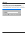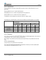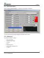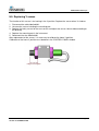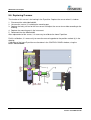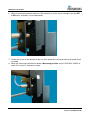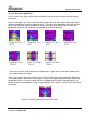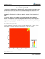
1
USER MANUAL CORESCAN Version 10.00 MRN-061-EN Master Registration Number: MRN-061-EN Manufacturer: Mechatronics Manufacturing B.V. Phone: +31 (0)229 - 29 11 29 Fax: +31 (0)229 - 24 15 34 E-mail: [email protected] Internet: http://www.mechatronics.nl Postal address: P.O. Box 225 1620 AE Hoorn The Netherlands Office address: De Corantijn 13 1689 AN Zwaag The Netherlands © Copyright Mechatronics BV All rights reserved. Subject to changes without prior notice. Issued by the After Sales Department of Mechatronics Document history overview Document history overview MRN-061-EN Published date Thursday, October 27, 2011 Issue No Date Revised Section(s ) 1.00 January 2002 All • First set-up of the manual for Corescan H.E. van Dijk 2.00 May 2002 All • General changes in the text. H.E. van Dijk 3.00 August 2002 • General corrections in the text and technical terms. H.E. van Dijk 4.00 April 2002 • Add LBIC in section Introduction H.E. van Dijk • Change some terms in section 3.1.3 • Update the screen shoots in section 5 • Add LBIC in section 5.1. • Add histogram text in section 5.4.1 • Add in section Maintenance Replace measuring holder. • Change in the specifications 2.1 • Change in software installation 3.1.3. • Add the Corescan extended settings to the section 5.1.1 till 5.1.4. • Add section 5.5.5 Set Corescan Model. • In section System messages correct the limits to the Corescan Extended. • Section 5.1.3. and Section 5.1.4. • Section 5.2.3. and Section 5.2.7. • Section 5.3.3. and Section 5.3.6. • Section 5.4.2.1. • Section 5.4.3. • Section 5.5.2.1 and Section 5.5.2.2 5.00 6.00 September 2004 February 2006 Corescan Version 10.00 MRN-061-EN Changes Authorised H.E. van Dijk H.E. van Dijk Page 3 Document history overview 7.00 June 2007 In all those section small text changes, added extra information or deleted some irrelevant text lines. • Section 4 added Check the Corescan model. • Placed colour pictures • Extra items on the Article list • Section 2, change text under the picture • Add more text in section, altering the mains input voltage. • Replace Control picture in section 5.5. • Add the associated text for the added option in section; • Section 5.1.6.3. Scan Direction • Section 5.2.1. Start button and • Section 5.5.5 Set Corescan model • Add alphabetical index • Small text changes H.E. van Dijk H.E. van Dijk H.E. van Dijk 8.00 November 2008 9.00 July 2009 • Change spot diameter from 9 till 10 mm section 1.1, 1.4 and 1.4.1 9.01 December 2010 • Section 2.2 List of OS extended • Section 5.1 Cell shape added • Section 5.1.7.4.8 Calibration setting changed • Small text changes • New chapter structure 10.00 Page 4 October 2011 All • All K. Artz H. Schavemaker Corescan Version 10.00 MRN-061-EN Contents CONTENTS 1. THIS MANUAL ............................................................................................................. 9 1.1. 1.2. Typographical Conventions.................................................................................... 11 General safety instructions..................................................................................... 12 1.3. Used symbols ........................................................................................................ 12 2. INTRODUCTION ........................................................................................................ 13 3. INSTRUMENT DESCRIPTION ................................................................................... 17 3.1. 3.2. 4. Technical specifications ......................................................................................... 17 Computer configuration.......................................................................................... 19 INSTALLATION ......................................................................................................... 21 4.1. Installation steps .................................................................................................... 21 4.1.1. Unpacking the Corescan ............................................................................. 21 4.1.2. List of contents ............................................................................................ 21 4.1.3. Switch ON sequence ................................................................................... 21 4.1.4. Corescan software installation ..................................................................... 21 4.1.4.1. Changing the mains input voltage ........................................................... 22 4.1.5. Corescan Hardware installation ................................................................... 22 4.2. First run of the application software ....................................................................... 22 4.2.1. Changing passwords ................................................................................... 23 5. GETTING STARTED .................................................................................................. 25 5.1. Start-up sequence ................................................................................................. 25 5.1.1. Placement of the solar cell .......................................................................... 25 5.2. Switch ON.............................................................................................................. 26 6. SOFTWARE ............................................................................................................... 27 6.1. SCAN SETTINGS tab ............................................................................................ 28 6.1.1. Cell shape ................................................................................................... 30 6.1.2. X-Length of the cell ..................................................................................... 30 6.1.3. Y width of the cell ........................................................................................ 30 6.1.4. D Diameter .................................................................................................. 31 6.1.5. Number of Bus-bars and Bus-bar distance .................................................. 31 6.1.6. X1, Y1, X2 and Y2 coordinates ................................................................... 32 6.1.7. Scan Type settings ...................................................................................... 32 6.1.7.1. Scan Type............................................................................................... 32 6.1.7.2. Cell type .................................................................................................. 32 6.1.7.3. Scan Direction......................................................................................... 33 6.1.7.4. Parameters ............................................................................................. 33 6.2. Measurement ......................................................................................................... 35 6.2.1. Start button ................................................................................................. 36 6.2.2. Remaining buttons ...................................................................................... 36 6.2.3. Scaling ........................................................................................................ 36 6.2.4. Reset .......................................................................................................... 36 6.2.5. Cursor icon.................................................................................................. 36 Corescan Version 10.00 MRN-061-EN Page 5 Contents 6.2.6. Text representations.................................................................................... 37 6.2.7. Cover detection ........................................................................................... 37 6.2.8. Cursor in the history record window ............................................................ 37 6.3. 2D/3D History ........................................................................................................ 38 6.3.1. Cursor icon.................................................................................................. 38 6.3.2. Scaling ........................................................................................................ 39 6.3.3. Reset .......................................................................................................... 39 6.3.4. Text representations.................................................................................... 39 6.3.5. Measurement Data file ................................................................................ 39 6.3.6. Cover status ................................................................................................ 39 6.3.7. Buttons [2D] and [3D] .................................................................................. 39 6.3.8. Buttons ........................................................................................................ 40 6.4. 3D History .............................................................................................................. 40 6.4.1. Scan evaluation button ................................................................................ 41 6.4.2. Window layout ............................................................................................. 41 6.4.3. Measurement data file ................................................................................. 42 6.4.4. Potential Range Settings ............................................................................. 42 6.4.5. Counters ..................................................................................................... 42 6.4.6. Limits .......................................................................................................... 42 6.4.7. Evaluation results ........................................................................................ 42 6.4.8. Counter Total and Progress bar .................................................................. 42 6.4.9. Buttons ........................................................................................................ 42 6.4.10. Histogram display ........................................................................................ 42 6.5. Control panel ......................................................................................................... 43 6.5.1. Manual movement ....................................................................................... 43 6.5.2. Outputs ....................................................................................................... 44 6.5.3. Home adjustment ........................................................................................ 44 6.5.4. Probe adjustment ........................................................................................ 45 6.5.5. Set Corescan model .................................................................................... 46 6.5.5.1. Size of vacuum table: .............................................................................. 46 6.5.5.2. Measure head: ........................................................................................ 46 6.5.6. Remaining buttons ...................................................................................... 46 7. DATA MANAGEMENT ............................................................................................... 47 7.1. Scan settings file.................................................................................................... 47 7.2. Measurement data file ........................................................................................... 47 8. SYSTEM MESSAGES ................................................................................................ 49 9. MAINTENANCE AND REPAIR .................................................................................. 51 9.1. Change measuring probe wire ............................................................................... 51 9.2. Replacing the measuring probe ............................................................................. 52 9.3. Replacing lamp ...................................................................................................... 53 9.4. 9.5. Replacing X sensor ................................................................................................ 54 Replacing Y sensor ................................................................................................ 55 9.6. Replacing Z sensor ................................................................................................ 56 9.7. Replacing Z sensor first step (6) ............................................................................ 57 9.8. Replacing cover sensor ......................................................................................... 59 Page 6 Corescan Version 10.00 MRN-061-EN Contents 10. APPENDIX FOR CORESCAN .................................................................................... 61 10.1.1. Introduction to Corescan ............................................................................. 63 10.1.2. Core Scan method ...................................................................................... 63 10.1.2.1. Core Scan application ........................................................................... 67 10.1.3. Shunt Scan method ..................................................................................... 69 10.1.3.1. Shunt Scan application ......................................................................... 74 10.1.4. Voc Scan method ........................................................................................ 76 10.1.4.1. Voc Scan application............................................................................. 76 10.1.5. LBIC scan method ....................................................................................... 78 10.1.5.1. LBIC scan application ........................................................................... 79 10.1.6. Conclusions ................................................................................................ 80 10.1.7. Reference ................................................................................................... 81 11. INDEX......................................................................................................................... 83 Corescan Version 10.00 MRN-061-EN Page 7 This manual 1. THIS MANUAL This manual describes all necessary procedures and information required for the correct and successful use of the Corescan, covering installation, normal operation, user maintenance and troubleshooting. This manual does not describe installation and specific service related issues, such as detailed technical information and repair procedures. This instrument is manufactured by Mechatronics BV, Zwaag, The Netherlands. Read the instructions before operating the instrument. Observe all cautionary markings in the manual and on the instrument. Keep this manual for future reference. Corescan Version 10.00 MRN-061-EN Page 9 This manual 1.1. Typographical Conventions Before you start using this guide, it is important to understand the terms and typographical conventions used in the documentation. For more information on specialised terms used in the documentation, see the Glossary at the end of this document. The following kinds of formatting in the text identify special information. Formatting convention Triangular Bullet() Type of Information Step-by-step procedures. You can follow these instructions to complete a specific task. Special Bold Menu selection Items you must select, such as menu options, command buttons, or items in a list. Emphasis Use to emphasise the importance of a point or for variable expressions such as parameters. [ TEXT ] Text of the menu line or from a menu TAB. [CAPITALS] Names of keys on the keyboard. for example, SHIFT, CTRL, or ALT. KEY+KEY Key combinations for which the user must press and hold down one key and then press another, for example, CTRL+P, or ALT+F4. Corescan Version 10.00 MRN-061-EN Page 11 This manual 1.2. General safety instructions • Do not spill fluids on to the instrument. This could cause a short-circuit. If this happens, turn the main switch OFF immediately and unplug the power cable. Contact your service representative. • Should the instrument emit unusual odours or smoke, turn the main switch OFF immediately and unplug the power cable. Using the instrument further carries the risk of fire, electric shock or personal injury. Contact your service representative. • Do not touch the electric circuits inside the instrument particularly with wet hands, as there is a risk of electric shock. • This instrument must be connected to a power outlet of the correct voltage. Please note that the instrument must be earthed. • Avoid damage to the power cable. Do not place any appliances on the power cable nor pull on the power cable. • When the instrument is not used (including overnight), the water supply must be closed to avoid water spillage accidents. • This instrument must only be opened as instructed in this manual. 1.3. Used symbols NOTE: This symbol indicates warnings and other danger related information. Ignoring this information could result in personal injury, damage to the instrument or property or malfunction of the instrument. Page 12 Corescan Version 10.00 MRN-061-EN Introduction 2. INTRODUCTION A visualization tool to locate losses in a solar cell is essential for process optimisation and in troubleshooting a non-optimal production line. Therefore, the Corescan instrument has been developed, in which four different locating methods are incorporated, the Core Scan, Shunt Scan, Voc Scan and the LBIC scan. The Core Scan method : series resistance sources can be detected by potential differences that occur over these resistances while current is flowing in the device. Figure 1: Schematic drawing Core Scan methode Corescan Version 10.00 MRN-061-EN Page 13 Introduction The Shunt Scan method: applies a bias across the cell with a power supply generates the current necessary to detect shunts. Figure 2: Schematic drawing of the Shunt Scan method The Voc Scan method: a potential probe centred in a light beam is scanned over the front surface of a cell without front side metallisation, while the cell is in open circuit condition. Page 14 Corescan Version 10.00 MRN-061-EN Introduction The LBIC scan method: scanning of a light beam over a cell while measuring the resulting short-circuit current for each position. Figure 3: LBIC method Corescan Version 10.00 MRN-061-EN Page 15 Instrument description 3. INSTRUMENT DESCRIPTION The instrument consists of the following parts: • X, Y, Z traverse axes. • A measuring head with a lamp and probe. • A table for mounting the solar cell. • Built in interface to communicate with a PC. Optionally extra weight can be added up to a maximum of 100 grams. 3.1. Technical specifications Mains supply 230 or 115 VAC 130 VA Power consumption Fuse (20x5 mm) Measuring environment Corescan Version 10.00 MRN-061-EN 50-60 Hz Slow blow 230 V 1.6 Amp Slow blow 115 V 3.15 Amp Temperature 15…30 C° Humidity level 80 % Vibration free --- Page 17 Instrument description Interface Serial 9 pin SUB D Measuring probe Diameter 0.2 mm Overall dimensions Width 809 mm Height 350 mm Depth 515 mm 28 Kg Total weight Min. table size Width (Including monitor) Depth Solar cell Thickness Width (Y-axis) 40…215 mm Light intensity Square, rectangle, circle, or combination, one part of cell 0…200 mW/cm² Light homogeneity ±5% Light stability ±5% Spot diameter 350…1,150 nm 10 mm X range 0…215 mm Y range 0…215 mm Z range 0…25 mm X speed 10…20 mm/s Y speed 10…20 mm/s X, Y, Z resolution Page 18 200…1,000 µm 25…215 mm Light wavelength X, Y, Z axis 600 mm Length (X-axis) Cell format Light source (1,200 mm) 800 mm 0.1 mm Corescan Version 10.00 MRN-061-EN Instrument description 3.2. Computer configuration The following minimum requirements are needed for the personal computer Processor Intern memory Pentium 1 GHz minimum 256 MB or higher CD drive Hard disk 50 MB minimum Keyboard Mouse RS232 Serial port COM1 or COM2 Able to communicate at 57,600 baud Operating system Windows 98, Windows 2000, Windows XP, Windows Vista, Windows 7 Display resolution 1,024 x 768 pixels minimum Corescan Version 10.00 MRN-061-EN Page 19 Installation 4. INSTALLATION Before unpacking the Corescan instrument, we recommend to check the package for any damage. Any damage must be reported to the distributor. 4.1. Installation steps 4.1.1. Unpacking the Corescan Remove the carton box. Then remove the two hex screws holding the instrument from underneath the crate. Unpack the instrument by removing the package. Unscrew and take away the transport bar that holds the measuring head of the Corescan in a fixed position. Remove the support holding from the measuring head. 4.1.2. List of contents The following items are in the package. • The Corescan instrument. • An accessories kit. See for details the appendix. 4.1.3. Switch ON sequence Before using the Corescan the first time, the following items must be attended. • Check the mains power voltage and corresponding fuse rate. • Check if the measuring head is free to move. • Check if the serial data cable is connected to the PC. • Connect the power lead into the socket. 4.1.4. Corescan software installation Insert the CD ROM in the CD drive and start the Windows Run program. Start “Setup.exe” on the CD-rom and follow the Windows Installer instructions. For the upgrades, and the latest version of software, refer to the manufacturer site www.mechatronics.nl Corescan Version 10.00 MRN-061-EN Page 21 Installation 4.1.4.1. Changing the mains input voltage The factory default voltage setting is set for 220-240 volt. To alter the input voltage setting reverses the fuse holder (3) so that the 110-120 volt arrow points to the white bar. Use the appropriate fuses and make sure to replace both fuses. • 3.15 Amp for 110-120 volt (QEDV130020) • 1.6 Amp for 220-240 volt 4.1.5. Corescan Hardware installation After finishing the software installation, connect the PC to the CoreScan by using the standard 9 pin 1 to 1 RS 232 cable (supplied with the instrument (QEDK130501)). Connect the female connector of the RS 232 cable to the PC serial port and the male connector to the female connector of the CoreScan. 4.2. First run of the application software After completion of the Corescan software, an icon is installed in the start menu of your computer. To start the Corescan program double click on the icon. The software is protected by two password levels, one for the supervisor and the other for the operator. In the first level all the necessarily parameters can be set and are protected from unattended change by the operator. The passwords can be changed into ones that are more appropriate. For the first start of the application software, the passwords are set to "toplevel" and "user". The first password for getting access at supervisor level is "toplevel". When logged in on this level the supervisor has access to all functionality of the software, such as changing parameters, password and manual access to the instrument. The first password for running the software by the operator is "user". When logged in on this level the operator can only operate the instrument and execute tests on the solar cells. Page 22 Corescan Version 10.00 MRN-061-EN Installation 4.2.1. Changing passwords The application starts and asks first for a password. Enter the appropriate password. To change the password, type the existing password and press the button < New Password >. To acknowledge, retype the new password and press the button < OK > or the < Return key >. The minimum length of the password is 3 with a maximum of 30 characters. If a wrong password is entered an error message will be displayed < Password not valid >. Corescan Version 10.00 MRN-061-EN Page 23 Getting started 5. GETTING STARTED Before using the Corescan the first time, the following items must be attended. • Check the mains power voltage. • Check that all safeties are removed. • Check that the measuring head is free to move. • Check the Corescan Model. (see section CONTROL PANEL Tab (on page 43)) 5.1. Start-up sequence To get started the following start-up sequence is needed. 1. Install the solar cell on the vacuum table of the Corescan. 2. Switch ON the Corescan and then the computer. 3. Start the Corescan software and run the application software for testing the solar cell. 5.1.1. Placement of the solar cell To hold the solar cell in place on the vacuum table, the instrument uses vacuum. To hold a cell in place with the maximum vacuum, not needed holes in the vacuum table can be closed. Use the lever to lift up the contact pins and place a solar cell in the bottom left corner indicated by the rulers as (X, Y) = (0,0). Close all remaining holes in the vacuum table that are not covered by the solar cell, with the M3x10 Hex screws. Use the provided screws (QWBM703010) and the Hex key (QWBM540004). To contact the solar cell (2) it is necessary to align the two contact pins (1) to the bus bars (3). Loosen the two bolts and move the pins exactly above the bus bars. Then lower the contact pins and fasten the two bolts. This must be done precisely since the instrument scans closely to the contact pins. Corescan Version 10.00 MRN-061-EN Page 25 Getting started Remark: For very uneven surfaces some air leakage can occur, resulting in a less firm contact. In case the fixation of the cell would not be enough to prevent displacement during scanning, it can be solved by placing a plate with the same height as the cell against the solar cell (open the holes below this plate). 5.2. Switch ON Switch ON the Corescan first. The instrument will perform a self-test and move the measuring head to the vacuum table origin. (Lower left corner) Page 26 Corescan Version 10.00 MRN-061-EN Software 6. SOFTWARE Start the application in Windows: Start the PC, run Windows and double click on the Corescan icon. The application starts and asks for a password. Enter the appropriate password. After getting access, the software will run. The software application starts with the SCAN SETTINGS window. On the window tabs are displayed, each leading to a window with different functionality. At the bottom of all windows, an error bar is shown. The following windows are available: • Scan settings • Measurement • 2D/3D History • Control panel Legend use in this paragraph: • Tabs like SCAN SETTING • Text buttons like "Stop", "Save" • Toggle-buttons like [p-type], [<=X] • Input parameters like Current Density, Scan Speed • Names of the keys on [ALT]+[PRINT SCREEN] the keyboard like In the program the buttons like "Save", "Save As..", "Open", "Print " and "Exit Program" are standard Windows functions for file handling, printing and to exit a program. Corescan Version 10.00 MRN-061-EN Page 27 Software 6.1. SCAN SETTINGS tab The Scan Settings window is used for the input of scan parameters. Page 28 Corescan Version 10.00 MRN-061-EN Software The dimensions of the solar cell must be entered with a tolerance of 0.1 mm. The rulers alongside the table can be used for cross-reference, for instance for the size of the solar cell and the location of the measuring head. The cell shape and dimensions X, Y, D and BB must be filled in to calculate the area to scan. The software will calculate a 1 mm probe safety margin around the edge of the solar cell. The values X1, Y1, X2 and Y2 can be used to just scan a limited part of a cell.Besides the parameters that determine the scan area boundaries, other parameters of scan setting can be filled in on the right side of the panel. The parameters that influence the scan time per unit of area are the scan line distance, the scan speed and the measuring directions such as both or only one direction. When a scan parameter is changed, a new estimated scan time will be calculated and displayed in the panel. Once setting up the entire scan parameters, clicking the "Start Test Run" button checks the correctness of the given parameters. In the Test run the probe will move along edges of the scan area and tip all scan line endpoints. The run can be stopped by clicking on the same button "Stop Test Run". All parameters can be saved to a file and recalled for later use. By exiting the program, using the "Exit Program" button, all current parameters are saved and will be used the next time when the program is started. The following scan parameter settings have to be set in the graphic presentation of the solar cell. • X is total length of the cell • Y is total width of the cell • D is the diameter of the cell • BB is busbar distance • X1, Y1, X2 and Y2 are the coordinates to select an area of the cell The software will perform all necessary calculation for the scans of the measuring head. It also takes into account the offsets, the form, and the dimensions of the solar cell and the location of the two busbars. Note: All the calculations are done for a symmetrical solar cell. Corescan Version 10.00 MRN-061-EN Page 29 Software 6.1.1. Cell shape The following cell shapes can be selected: Rounded Rectangle: see picture at scan settings. Rectangle Round 6.1.2. X-Length of the cell X is the total length of the solar cell. The value for X must be for Corescan: >= 25 and <= 205 mm. For the Corescan Extended: >= 25 and <= 215 mm. A warning is given if the value is outside this range. X is not available for cell shape "Round". 6.1.3. Y width of the cell Y is the total width of the solar cell. The value for Y must be for Corescan: >= 40 and <= 205 mm. For the Corescan Extended: >= 40 and <= 215 mm. A warning is given if the value is outside this range. Y is not available for cell shape "Round". Page 30 Corescan Version 10.00 MRN-061-EN Software 6.1.4. D Diameter D is the diameter of the solar cell. This value is needed if the cell is circular or a rounded rectangle. The value for D must be for Corescan: >= value of Y and <= 290 mm. For the Corescan Extended: >= value of Y and <= 305 mm. A warning is given if the value is outside this range. This value is not available for cell shape "Rectangle". 6.1.5. Number of Bus-bars and Bus-bar distance The number of Bus Bars on the cell to be tested can be selected by clicking the appropriate box. The figure will automatically display the selected number, and the BusBar to Bus Bar distance (BB) to be filled in. It is assumed that the BusBars are positioned symmetrically on the cell. So, in case three Bus Bars, one has to fill in the distance for the two Bus Bars that are on the sides of the cell. The minimum and maximum values are 0 and 215 for Corescan. For Corescan Extended the maximum is 225. In case a non-correct value is typed in, the box shows a blinking red colour. In this case the measurement can still be executed. For the Voc-scan mode one should work withuot using the contact pins. To scan the complete cell one can omit the BusBars locations by using the settings 2 or 3 BusBars and setting BB>Y(=cell width) and remove the contact pins. The minimum cell dimensions depending on the number of Bus Bars are given in the table below: The minimum BusBar distance (BB) with 2 or 3 BusBars is given by the expression below: #Bus Bars 1 X (mm) Y (mm) 25 40 BB (mm) NA 2 25 50 15 3 25 65 30 The maximum Bus Bar distance (BB) with 2 or 3 BusBars is given in the expression below: Max BB (mm) = Y (mm) - 35 mm Corescan Version 10.00 MRN-061-EN Page 31 Software 6.1.6. X1, Y1, X2 and Y2 coordinates X1, Y1, X2 and Y2 are the coordinates of a selected part of the cell. If the coordinate values are zero than the complete solar cell will be scanned. If the values are > 0 only that part of the solar cell will be scanned. 6.1.7. Scan Type settings In the SCAN SETTINGS window, the following settings can be made or changed by clicking on the Indicator with the mouse cursor. • Scan Type • Cell Type • Scan Direction • Parameters 6.1.7.1. Scan Type Here the choice for the scan type is made, [Core Scan], [Voc Scan], [Shunt Scan] or [LBIC Scan]. The brightness of the indicator next to the text shows this mode is active. 6.1.7.2. Cell type The cell type is only effective for the Shunt Scan. Depending on the cell type, a different polarity must be applied for forward biasing of the cell during the Shunt Scan. The brightness of the indicator next to the text shows this mode is active. For [p-type] cell, the vacuum table is positive compared to the front side of the cell. For [n-type] cell, the vacuum table is negative compared to the front side of the cell. Page 32 Corescan Version 10.00 MRN-061-EN Software 6.1.7.3. Scan Direction The scan direction menu gives the possibility to make a choice in which direction the scan is performed. Button [<=X=>]: the scan is made in both directions. Button [X=>]: the scan is made in the right direction only (positive X). Button [<=X]: the scan is made to the left only (negative X). The brightness of the indicator next to the text shows this mode is active. According to the selected probe (see Set Corescan Model) the following options are available: Scan direction <= X => 60° X => 90° 60° <= X 90° 60° 90° CoRe Scan ● ● ● ● Voc Scan ● ● ● ● Shunt Scan ● ● ● ● ● ● ● Lbic Scan ● ● ● 6.1.7.4. Parameters On the right-hand side of the SCAN SETTINGS window, the following parameters have to be set. The parameters values can be saved to a parameter file. Bias voltage is only effective for Shunt Scan and Current Density is only effective for the Core Scan 6.1.7.4.1. Current density Current Densityis only effective for the Core Scan. This is the current density generated within the light beam. Normally a maximum power point current density of around 30 mA/cm2 is used. Corescan Version 10.00 MRN-061-EN Page 33 Software 6.1.7.4.2. Bias voltage Bias Voltage is only effective for Shunt Scan. This is the absolute value of the applied bias in case of a Shunt Scan. Allowed values are 100 until 500 mV. Normally, use 300 mV to investigate shunt behaviour at maximum cell power. 6.1.7.4.3. Lamp voltage Lamp Voltage is only effective for the LBIC scan. Voltage adjustment for the lamp express in percent of the voltage. 6.1.7.4.4. Scan Line spacing Scan Line Spacing is the distance between the measured scan line and the next measured scan line. 6.1.7.4.5. Scan Speed Scan Speed is the speed of the measuring head during measuring. Default value is 20 mm/sec. The minimum speed setting is 10 mm/sec. A scan speed of 20 mm/sec is recommended for fast scanning of the cell. 6.1.7.4.6. Finger Spacing and Finger Width Finger Spacing and Finger Width are only effective for Core Scan. The finger spacing and the finger width are needed to calculate the contact resistance. The Corescan calculates contact resistance using two different definitions, the line contact resistance and the more familiar specific contact resistance. See for more details The introduction. Both values are displayed in the measurement panel of the Corescan. 6.1.7.4.7. Expected Scan Time Expected Scan Time is the estimated scan time, which is updated if relevant parameters are changed. 6.1.7.4.8. Location Core Scan Calibration To set new coordinates for a location on the solar cell enter the position coordinate in the X and Y in mm. These are the coordinates of the location where the measuring head is positioned for calibrating the generated current density. This calibration is done every time a scan is performed. The location must be chosen on a representative part of the cell, meaning e.g. that no light must be lost by busbar shadowing or light falling next to the cell. The closer this location is to the X-Y origin the faster the scanning is. The lowest possible setting is 10.0 mm for both coordinates. Page 34 Corescan Version 10.00 MRN-061-EN Software 6.2. Measurement The MEASUREMENT window shows a representation of the measured data for the tested solar cell. The window shows two 2D graphical windows. The top graphical window shows the measured data along one scan line. The square graphical window represents the history of the collected scan data. The small coloured bar next to the square window represents the density code of the measured values. To perform a scan, first fill in the scan settings in the SCAN SETTINGS window. When "Save Scan As" the program asks for a file name and the results can be saved. The window can be copied to the clipboard by pressing at the same time [ALT]" and "[PRINT SCREEN] buttons at the keyboard. Clicking a window with the mouse (right button) gives also the possibility to save or alter the graphs. Corescan Version 10.00 MRN-061-EN Page 35 Software 6.2.1. Start button This button has a toggle function. When selected the text change from [Start] to [Stop] and visa versa. Next to the text "Start" or "Stop" the name of Scan type function is displayed, "Core Scan", "Voc Scan", "Shunt Scan" or "LBIC Scan". When a scan start the program asks automatically for a file name for saving the results. When the file dialog box has been cancelled the program will ask for a file name after the scan is finished. 6.2.2. Remaining buttons The remaining buttons "Save Scan As" and "Exit Program" are standard Windows functions for file handling and exiting the program. 6.2.3. Scaling All the displayed graphical windows have the possibility of scaling. Move the "mouse cursor" to any number (potential or X or Y value) along the graphic window and alter the number to an appropriate value. Both the upper and lower values of the scaling can be adjusted in this way. 6.2.4. Reset The button “reset” is used to reset the mV-scale. The button “reset axis” is used to reset the X, Y scaling. 6.2.5. Cursor icon The cursor icon is next to the square history record window and above the density colour bar. Click in one of the directional arrows to move the hair crossing cursor to the selected direction. Page 36 Corescan Version 10.00 MRN-061-EN Software 6.2.6. Text representations In the square history record window at the cursor location, the following values can be read regarding the selected scan type. Meanings Core Scan Voc Scan Shunt Scan X position Value in mm on the X axis Yes Yes Yes Y position Value in mm on the Y axis Yes Yes Yes Potential contact Voltage in mV on that location Yes Yes Yes Resistance on that location in mΩcm2 Yes No No Yes No No Resistance Line contact Resistance on that location in Ωcm Resistance 6.2.7. Cover detection The cover status indicates whether the cover was opened during (part of) the measurement or closed during the complete measurement. 6.2.8. Cursor in the history record window Move the mouse cursor to the X-Y crossing and move the cross hair to any location in the square history record window of the solar cell. When moving the cross hair in the square history record window, automatically the cursor in the scan line window will move and actual scan line data will appear in the scan line data window. Corescan Version 10.00 MRN-061-EN Page 37 Software 6.3. 2D/3D History The 2D/3D HISTORY window displays the results in of the stored measurement data in more detail. The 2D style graph is a copy of the MEASUREMENT window. The recorded data are presented in a large graphic window for a more detailed view. Scan line information is present in a "history record window". The coloured bar next to the large graphic window represents the colour code to the measured values. 6.3.1. Cursor icon The cursor icon is positioned next to the history record window and above the density bar. Click with mouse cursor in one of the direction arrows to move the hair crossing cursor one step to the selected direction. Page 38 Corescan Version 10.00 MRN-061-EN Software 6.3.2. Scaling The X, Y and potential values as displayed in both windows, can be scaled by clicking these values with the mouse cursor and changing the numbers to a required value. 6.3.3. Reset The button “reset” is used to reset the mV-scale. The button “reset axis” is used to reset the X, Y scaling. 6.3.4. Text representations At the hair crossing cursor location in the 2D/3D graphic window, the following values can be examined for the selected scan type. Meanings Core Scan Voc Scan Shunt Scan X position Value in mm on the X axis Yes Yes Yes Y position Value in mm on the Y axis Yes Yes Yes Potential contact Voltage in mV on that location Yes Yes Yes Resistance on that location in mΩcm2 Yes No No Yes No No Resistance Line contact Resistance on that location in Ωcm Resistance 6.3.5. Measurement Data file Displays the name and the location of the selected data file. 6.3.6. Cover status The cover status indicates whether the cover was opened during (part of) the measurement or closed during the complete measurement. 6.3.7. Buttons [2D] and [3D] Select 2D or 3D representation of collected data. Corescan Version 10.00 MRN-061-EN Page 39 Software 6.3.8. Buttons The buttons "Print", "Open scan" and "Exit Program" are standard Windows functions. "Open scan" is used for selecting a data file to be displayed. "Exit Program" is used to exit the program. "Print" will make a screen dump and send data to the local printer. 6.4. 3D History The 3D History window is a 3D presentation of the measured data. The scan line information is now present in a smaller window. Page 40 Corescan Version 10.00 MRN-061-EN Software 6.4.1. Scan evaluation button When the button "Scan evaluation" is selected, the next window is displayed: The view angle can be altered by dragging the 3D-graph with the mouse. 6.4.2. Window layout This window is divided in sections: • File name window • Potential range settings • Counters • Limits • Evaluation results • Counter total and progress bar • Histogram Corescan Version 10.00 MRN-061-EN Page 41 Software 6.4.3. Measurement data file Displays the name and the location of the selected data file. 6.4.4. Potential Range Settings Input segment for five selections of boundaries for the measured data values. 6.4.5. Counters The counters display the number of measured points that fit into the chosen range. The next display gives the percentage of points in the chosen range that corresponds to the counter value compared to the counter total value. 6.4.6. Limits Input segment for five selections used to give an upper limit for the counters. When a counter exceeds this limit the corresponding fail indicator turns red. 6.4.7. Evaluation results The cell indicators indicate where a counter percentage exceeds the limit and consequently the cell results to be out of range. 6.4.8. Counter Total and Progress bar Counter shows the total number of collected data points from the tested solar cell. The progress bar shows the progress of the scan evaluation. 6.4.9. Buttons The buttons "Start", "Stop", "Exit Program" and "Print" are standard Windows functions for program manipulations, to exit the program and to print a screen dump to the local printer. With the buttons “save evaluation” and “open evaluation” the current evaluation set-up can be stored and previously stored evaluation set-ups can be re-called. 6.4.10. Histogram display The histogram display shows a graphic interpretation in percents of the spreading of the measured data. In the window Interval length the width of histogram bar can be set. Page 42 Corescan Version 10.00 MRN-061-EN Software 6.5. Control panel The CONTROL PANEL window has various tools for e.g. manually moving the measuring head, probe settings, calibration and switching functions. Some of the functions are user level dependent. In this figure the lay out of the CONTROL PANEL tab is given. 6.5.1. Manual movement A movement in X, Y or Z direction can be made by typing in an input value and pressing the "Go To Position" button. Corescan Version 10.00 MRN-061-EN Page 43 Software 6.5.2. Outputs The following outputs can be selected: Vacuum Pump switch Move mouse cursor to the button and toggle the "Vacuum Pump" switch. The pump will switch on or off. This is for testing purpose only. During the measurements the vacuum is switched on automatically and after the measurement it is switched off automatically. Lamp voltage Input the percentage of the voltage of the lamp from 0% until 100%. This setting is for test purpose only and will not be used during scanning. Select Serial Port Selects the [COM1] or [COM2] ports for communications. 6.5.3. Home adjustment The instrument is delivered with the "machine zero" already set. These functions should only be used if one of the home sensors is replaced or misaligned. Care should be taken when performing these functions since they can damage the instrument if not properly adjusted. Home X Adjustment When the home X adjustment button is activated the measuring head goes to the Y=100 and the X=0 position. Now it is possible to make a correction of the zero-position in the X-direction using the manual movement X. The new home position is stored using the "Set To Home" button. Home Y Adjustment When the home Y adjustment button is activated the measuring head goes to the X=100 and the Y=0 position. Now it is possible to make a correction of the zero-position in the Y-direction using the manual movement Y. The new home position is stored using the "Set To Home" button. Home Z Adjustment When the home Z adjustment button is activated the measuring head goes to the Z=0 position. Now it is possible to make a correction of the zero-position in the Z-direction. The new home position is stored using the "Set To Home" button. Page 44 Corescan Version 10.00 MRN-061-EN Software 6.5.4. Probe adjustment This button can be used to adjust the length of the measuring probe. The ideal length of the probe is between 0.1 until 1.2 mm and can be adjusted with the cartel wheel on the side of the measuring head. If the warning "Probe Too Short" shows, adjust the cartel wheel clockwise until the probe OK signal is green. If the warning "Probe Too Long" shows, adjust the cartel wheel anti-clock wise until the probe OK signal is green. After adjustment, press the button "OK". Corescan Version 10.00 MRN-061-EN Page 45 Software 6.5.5. Set Corescan model 6.5.5.1. Size of vacuum table: It is important to set the correct type in this setting. The type of instrument can be found on the instrument plate. Corescan Type SCRA109000 the settings are 205x205 mm. Corescan Extended type SCRA109001AA the settings are 215x215 mm. 6.5.5.2. Measure head: Two selections are possible: - 60 degrees Probe - 90 degrees Probe This setting affects the scan direction (see also Scan Direction (on page 33)). An incorrect setting will damage the measure head (probe)! 6.5.6. Remaining buttons The "Exit Program" button will exit the program, "Move X, Y, Z to Origin" button will reset the Corescan and moves the measuring head to the origin. When the Corescan does not respond to a reset it should be switched OFF and ON again. Page 46 Corescan Version 10.00 MRN-061-EN Data management 7. DATA MANAGEMENT The communication between the PC and the Corescan is via serial communication. The default setting for the communication port in the Corescan is 57600 8-n-1. 7.1. Scan settings file Customised cell parameters and settings information can be stored in text format in the scan settings file. The scan line information is stored in the following sequence: First Y coordinate, Start coordinate X, Stop coordinate X. The coordinates are given in 0.1 of millimeters The first axis determines whichever the X or the Y-axis starts moving first. 7.2. Measurement data file All cell parameters, settings, which scan type, cover position and measured data can be stored in text format in the measurement data file. The measured data is stored in the following way: X coordinate, Y coordinate, Measured data The coordinates are given in 0.1 millimeters. The measured data are stored in 0.1 mV. The format of the data string is XXXX<TAB>YYYY<TAB>DDDD<CR>. An extra Carriage Return is saved after every scan line. Corescan Version 10.00 MRN-061-EN Page 47 System messages 8. SYSTEM MESSAGES The system messages are present in two types of windows: • An error window will flash when an error is detected. • A warning window will flash when an interrupt or out of range is detected. Errors are divided in two groups: non-fatal and fatal faults. When a fatal error occurs the instrument must be reset using the on/off switch. The following warnings are possible 900 Process interrupted by user 904 Cell voltage during shunt measurement low Fatal error 926 No communication with motor drivers 927 Fault in X - axis 928 Fault in Y - axis 929 Fault in Z - axis 930 Positioning command Y - axis while Z - axis Error 901 Probe too short 902 Probe too long 903 Core Scan current not reached 905 Wrong parameter(s) 906 Vacuum off 940 Core Scan not found 950 "X" Out of range (25 …205)* "X" Out of range (25 …215)** 951 "Y" Out of range (40 …205)* "Y" Out of range (40 …215)** 952 "D" Out of range ("Y" …290)* "D" Out of range ("Y" …305)** 953 "BB" Out of range (0…215)* "BB" Out of range (0…225)** Corescan Version 10.00 MRN-061-EN Page 49 System messages 954 "X2" Out of range (0…"X") 955 "X2" Out of range (0…"X") 956 "Y1" Out of range (0…"Y") 957 "Y2" Out of range (0…"Y") 958 "Scan line spacing out of range (0.1…40) 959 "X1" = "X2" 960 "Y1" or "Y2" out of range 961 "Y1" = "Y2" = 0 970 No scan lines 971 No test run points * For Corescan (SCRA109000) ** For Corescan Extended (SCRA109001AA) Page 50 Corescan Version 10.00 MRN-061-EN Maintenance and repair 9. MAINTENANCE AND REPAIR The following maintenance and repair action could occur will be needed when running the Corescan. 9.1. Change measuring probe wire When the wire is completely used during scanning (after approximately 10,000 scans) the probe wire should be changed. 1. 2. 3. 4. 5. 6. Move the cartel wheel (3) anti-clock wise until the old probe wire can be removed. Push the lever (1) down. Place the new probe between the transport rollers (2) and push the wire into the probe tube (4). Release the lever (1). Turn the cartel wheel (3) clockwise until the probe comes out of the probe tube. Calibrate probe length in the CONTROL PANEL window under probe adjustment. the Corescan Corescan Version 10.00 MRN-061-EN Page 51 Maintenance and repair 9.2. Replacing the measuring probe 1. 2. 3. 4. 5. 6. Use nippers to pull the pin what is locate at number 6. Unscrew the screw in location number 5. Take the measuring probe from the holder. Replace the new measuring holder. Replace the screw in location 5. Push the pin back in location number 6. Page 52 Corescan Version 10.00 MRN-061-EN Maintenance and repair 9.3. Replacing lamp 1. 2. 3. 4. 5. 6. 7. 8. 9. Disconnect the lamp cable. Remove the screws out of the lid. Take off the lid. Unscrew the two screws that hold the lamp in place. Remove the old lamp. Place the new lamp. Screw the two screws back that hold the lamp in place. Put the lid back. Replace the screws back into the lid. Corescan Version 10.00 MRN-061-EN Page 53 Maintenance and repair 9.4. Replacing X sensor The function of this sensor is for homing in the X-position. Replace the sensor when it is broken. 1. Disconnect the cable labelled 302. 2. Unscrew the sensor including the mounting part of the instrument. 3. Replace the faulty sensor for the new sensor and adjust the sensor to 14 mm wide according to the drawing. 4. Replace the mounting part in the instrument. 5. Reconnect the wire labelled 302. After replacement of the sensor it is necessary to calibrate the home X position. Calibration of the home X position must be done in the CONTROL PANEL window. Page 54 Corescan Version 10.00 MRN-061-EN Maintenance and repair 9.5. Replacing Y sensor The function of this sensor is for homing in the Y-position. Replace the sensor when it is broken. 1. Disconnect the cable labelled 301. 2. Unscrew the sensor including the mounting part. 3. Replace the faulty sensor for the new sensor and adjust the sensor 10 mm wide according to the drawing. 4. Replace the mounting part in the instrument. 5. Reconnect the wire labelled 301 After replacement of the sensor, it is necessary to calibrate the home Y position. Calibration of the home Y position must be done in the CONTROL PANEL window. Corescan Version 10.00 MRN-061-EN Page 55 Maintenance and repair 9.6. Replacing Z sensor The function of this sensor is for homing in the Z-position. Replace the sensor when it is broken. 1. Disconnect the cable labelled 402. 2. Unscrew the sensor (1) including the mounting part. 3. Replace the faulty sensor for the new sensor and adjust the sensor 8 mm wide according to the drawing. 4. Replace the mounting part in the instrument. 5. Reconnect the wire labelled 402. After replacement of the sensor, it is necessary to calibrate the home Z position. For this calibration, it is necessarily to move the measuring probe to the position marked (4) in the drawing. Calibration of the home Z position must be done in the CONTROL PANEL window, using the button "Set to Home". Page 56 Corescan Version 10.00 MRN-061-EN Maintenance and repair 9.7. Replacing Z sensor first step This sensor is to stop movement of the measuring head in Y direction when the probe goes to the next new coordinate or measure position of the solar cell. 1. 2. 3. 4. Replace the sensor if broken. Disconnect the cable labelled 403. Unscrew the sensor (2) from the instrument. Replace the faulty sensor for the new sensor and adjust the sensor 0.5 mm wide according to the drawing. 5. Reconnect the wire labelled 403. After replacement of the sensor, it is necessary to calibrate the Z-axis first step position. The calibration of Z-axis first step position must be done in the CONTROL PANEL window. 1. 2. 3. 4. 5. Switch ON the Corescan The positions of the X, Y and Z will automatically be detected. Mount the white cap over the probe head. Place the Z-axis in a new position by using Manual Movement Z, clicking on indicator “Z=200”. Move the measuring head with the button "Movement position" on the CONTROL PANEL. Corescan Version 10.00 MRN-061-EN Page 57 Maintenance and repair 6. Adjust the horizontal position when the LED indicator (3) in the sensor changes from the OFF to ON status and lower it 2 mm downwards. 7. Fasten the sensor in that location to be sure it will detect the correct position of the probe head assembly. 8. Move the measuring head with the button "Measuring position" on the CONTROL PANEL to check if the sensor is located as shown: Page 58 Corescan Version 10.00 MRN-061-EN Maintenance and repair 9.8. Replacing cover sensor The function of this sensor is to detect if the cover is open or closed. Replace the sensor if broken 1. Disconnect the cable labelled 107. 2. Unscrew the sensor from the instrument. 3. Replace the faulty sensor for the new sensor and adjust the sensor according the drawing Replacing Z-sensor. 4. Reconnect the wire labelled 107. 5. Adjust the sensor so that the LED indication in the sensor is on if the cover is closed. Corescan Version 10.00 MRN-061-EN Page 59 Appendix for Corescan 10. APPENDIX FOR CORESCAN Appendix section Corescan Version 10.00 MRN-061-EN Page 61 Appendix for Corescan Appendix - Accessories Corescan The Corescan comes with a complete accessories kit (SCRA 109007). Part number QEDK100001 Description Power Cable 230/115VAC QEDK130501 Cable RS232 (SUBD-9 male-female) QEDV130020 3.15 fuse QWBM412010 Screw to fix the weight QWBM540004 Hex key 1,5 mm QWBM540008 Hex key 4 mm QWBM703010 Screw M3x10 (10x) SCRA010023 Weight 20 gram SCRA010032 Weight 50 gram SCRA019003 Measuring probe holder SCRA019004 Measuring probe holder 60 degree SCRA019008 Measuring probe (6x) SCRA019010 Lamp assembly SCRA069001 Contact pin assembly SCRA100002 User manual SCRA109014 CD Software Corescan Page 62 Corescan Version 10.00 MRN-061-EN Appendix for Corescan Appendix - General introduction to the CoreScan 10.1.1. Introduction to Corescan A visualization tool to locate losses in a solar cell is essential for process optimisation and in troubleshooting a non-optimal production line. Therefore, the Corescan instrument has been developed, in which four different locating methods are incorporated, the Core Scan, Shunt Scan, Voc Scan and the LBIC scan. In this chapter, it is explained how these scan methods work and how the results can be interpreted. Several examples of how the Corescan instrument can be used for troubleshooting and process optimisation are presented. These examples will help users of the instrument to relate measured scans with causes for non-optimal processing. 10.1.2. Core Scan method Figure 4: Schematic drawing Core Scan methode The Core Scan method, uses the fact that series resistance sources can be detected by potential differences that occur over these resistances while current is flowing in the device. In the Corescan instrument, the current is generated by local illumination while the cell is short-circuited externally. The potential at the front side is measured with a metal probe in direct contact with the surface. The probe is scanned across the cell. The contact resistance of a finger is proportional to the potential jump Vce across the contact interface at the edge of the finger. This jump is the difference between the potential at the metal finger and the first point on the adjacent silicon (see Fig. 2). The proportionality factor is 1/ic, where ic is the current flowing through the contact interface per unit length of finger. In formula form: Corescan Version 10.00 MRN-061-EN Page 63 Appendix for Corescan Recently, it has been found that the substitution of ic by Jsc d in the formula for Rcl results in too low values for Rcl ., where Rcl is the line contact resistance, Jsc is the short circuit current density within the beam and d is the distance between two fingers. Recently, it has been found that the substitution of ic by Jsc d in the formula for Rcl results in too low values for Rcl., where Jsc is taken as the total generated current divided by the beam area. This is due to current leakage to the dark area around the beam (which is at a lower potential than within the beam) and shadowing of the cell by the potential probe. To correct for these effects, a modified formula must be used for the calculation of Rcl : Page 64 Corescan Version 10.00 MRN-061-EN Appendix for Corescan where C is a correction factor for the effects mentioned above. Its value was determined empirically by dividing Vce at a certain location for uniform 1-sun illumination by the Vce as found by the Corescan (with Jsc=Jsc,1 sun) at the same location: It was found that: so that this value has now been incorporated in the calculation of Rcl within the Corescan software. In earlier versions of the software (up to version 2.2), this correction was not used. There are no consequences for the interpretation of the data as far as the colours in the scans are concerned, since the measured mV values remain the same. What changes is the absolute value that is found for the line contact resistance and specific contact resistance that are indicated when using the cursor in the colour graphs: these values are increased by a factor of 1.8. It should be noted that the value of C is probably somewhat dependent on the contact resistance itself and will also be different near the cell edges (because current cannot exit the cell). Therefore, the determination of the absolute value should not be considered very precise, it is however the best that can be done in the given circumstances. Because the Corescan is almost always used in a relative way, the inherently limited absolute accuracy for contact resistance is not of vital importance in practice. This line contact resistance is used instead of the more usual specific contact resistance ρc, because ρc is not so appropriate for screen printed contacts. This is because calculating ρc correctly involves the emitter sheet resistance below the finger and the assumption of a constant ρc across the finger width. However, the emitter sheet resistance below screen printed fingers increases to an unknown value during sintering due to dissolving of silicon, and the contact interface is very non-uniform. Instead of trying to separate the influence of ρc and emitter sheet resistance, the definition of Rcl includes both parameters in a single value. In the Corescan instrument, for practical reasons local illumination is used, the diameter of the beam is 10 mm. The probe is scanned perpendicular to the fingers with a resolution of 0.1 mm so that no finger is missed. To scratch through the usual isolating anti-reflection coating, the probe is continuously in contact with the surface during the scan and is made of a hard material. By performing scan lines with a separation of 2 mm, it is possible to obtain a potential map of the entire cell, which takes about 6 min for a 10 x 10 cm cell. An example of a scan line part is shown in Fig. 2. Corescan Version 10.00 MRN-061-EN Page 65 Appendix for Corescan The potential jumps at the fingers due to contact resistance are clearly visible; the large spread in Rcl on this cell is typical for cells with a contact problem. The influence of other series resistance sources is also visible: the emitter sheet resistance causes a parabolic potential behaviour between the fingers and a finger discontinuity causes effectively doubled finger spacing. The large non-uniformity of Rcl that is often found on solar cells causes high diode factors or second diode currents when fitting the J-V curves. The minimum contact resistance that can be measured with the Corescan instrument can be calculated from the minimum measurable Vce and maximum Jsc for the instrument. These values are 2 mV and 60 mA/cm2, so for a typical finger spacing of 2 mm, the minimum Rcl is ~0.2 Ωcm. For reference: this would correspond to ρc~2 mΩcm2, assuming a constant ρc across the finger width and assuming a sheet resistance below the finger of 100Ω. This accuracy of the Core Scan is more than sufficient, since the influence of such a low contact resistance is negligible for illuminations up to 1 sun. Page 66 Corescan Version 10.00 MRN-061-EN Appendix for Corescan 10.1.2.1.Core Scan application In this section, Core Scans will be shown for different causes of high (and non-uniform) contact resistance. In the first example, 10 x 10 cm multi-crystalline silicon solar cells with silicon nitride were fired at different temperatures around an optimum value T. Contacts were applied by screen printing and co-firing of aluminium paste on the back side and silver paste on the front side. The cells are positioned on the belt with the busbars perpendicular to the belt direction. Figure 5: FF 72 %, T45 °C Figure 6: FF 74 %, T30 °C Figure 7: FF 74%, T15 °C Figure 9: FF 74 %, T+15 °C Figure 10: FF 69 %, T+30 °C Figure 11: FF 62 %, T+45 °C Figure 8: FF 75 %, T+0 °C Core Scans on cells fired at different set temperatures. Lighter areas have higher potential and thus higher contact resistance. These scans show a large non-uniformity in Rcl which is due to cross-belt temperature differences. The middle region is the coolest: in this region it is too cold for good contact formation at low firing temperature, while it is the only region that has still good contact at high firing temperatures. An emitter related contact problem is shown in figure below, which shows a circle of increased contact resistance. Figure 12: Circle of increased contact resistance Corescan Version 10.00 MRN-061-EN Page 67 Appendix for Corescan Circle of increased contact resistance due to locally less doped emitter This circle is caused by application of dopant on the cell by spinning of a phosphorus containing fluid on both sides (the backside is overcompensated with aluminium later on). On the surface that was spun first, some fluid has been removed at the circle when dopant was applied to the second surface. Due to less dopant fluid the emitter resistance is increased, apparently to a value too high for good contact formation. Although this particular example may not be a very usual one, it is a good illustration of the effect of emitter non-uniformity that can also be caused otherwise. These lateral doping variations become especially important when lighter doped emitters are used in order to reduce recombination losses in the emitter. The next example is a contact problem caused by plasma etching of the solar cell edges for isolation (see figure below). Figure 13: Increased contact resistance at the edges due to some emitter removal during plasma etching for edge isolation The figure shows that the contact resistance is clearly increased near the edges of the front surface. Apparently some of the emitter on the front surface has been removed during the plasma etching, which was done immediately after emitter diffusion. Some other causes for Rcl non-uniformity that have been identified so far are: • Incomplete phosphorus glass removal, • The presence of contamination on the silicon before contact firing, • Non-uniform TiOx coating [11], and • Too low and non-uniform screen-print pressure due to a wear dip on the screen printer vacuum chuck [92]. 1 A.S.H. van der Heide, A. Schönecker, G.P. Wyers, W.C. Sinke, 16th European Photovoltaic Solar Energy Conference, Glasgow (United Kingdom), 1438 (2000) 2 A.S.H. van der Heide, J.H. Bultman, J. Hoornstra and A. Schönecker, 12th Photovoltaic Science and Engineering Conference, Jeju (Korea), 591 (2001) Page 68 Corescan Version 10.00 MRN-061-EN Appendix for Corescan 10.1.3. Shunt Scan method For the Shunt Scan, applying a bias across the cell with a power supply ) generates the current necessary to detect shunts. Figure 14: Schematic drawing of the Shunt Scan method In order to study only shunt current flow, current generation by light is avoided by measuring in the dark. The surrounding emitter area supplies the current flowing through a shunt. Then, a potential decrease in the direction of the shunt will exist due to the sheet resistance of the emitter. In a Shunt Scan this local potential decrease is detected; the magnitude of the shunt can be calculated from the potential gradients around it and the emitter sheet resistance. To find the shunts that are important for the cell at normal operation, it is necessary to apply a forward bias to the cell. The reason is that not all shunts in solar cells are ohmic [10], so that shunts detected in reverse bias may not be shunts in forward bias. The Shunt Scan is sensitive enough to detect shunts at forward bias. Except for lock-in techniques, the other methods that use heat detection to locate shunts have to use reverse bias to induce sufficiently high shunt currents. The magnitude of the forward bias applied during the Shunt Scan is adjustable. Ideally it should be around the maximum power point (~0.5 V), but since the scratching of the probe itself induces some extra diode current, due to surface damage, it is better to use ~ 0.3 V. At that potential the diode is not conducting (even when scratched) and all currents are caused by shunts. To calculate the current detection limit for the Shunt Scan, the potential distribution V (r) around a shunt must be calculated. This is described by the general equation: Corescan Version 10.00 MRN-061-EN Page 69 Appendix for Corescan As an example, V(r) is drawn for two different Ish values in Fig. 7. Page 70 Corescan Version 10.00 MRN-061-EN Appendix for Corescan Figure 7: V(r) for 2 different Ih values; ρs= 50 Ω. The shunt with the larger Ish clearly has a much larger area with lower potential around it. The current detection limit of the Shunt Scan can now be estimated; the smallest shunt that can be detected is determined by the smallest potential difference that can be detected when moving from “the shunt” to r = 1.0 mm (to stay between the fingers on a real cell). “The shunt” means here the point as closest as possible to it, since the potential probe itself has a finite diameter (in this case 0.2 mm). Taking r ‘at shunt’ = 0.1 mm, r ‘far away’ = 1.0 mm, ρs = 50 Ω and minimum ∆V = 5 mV, the minimum detectable current for a single shunt turns out to be ~ 0.25 mA. Compared to a current at the maximum power point of a 10 x 10 cm cell of 3 A, this would mean 0.01 %, so that the sensitivity for a single shunts on an otherwise non-shunted surface is more than sufficient. In practice, the ideal case of current flow only through one shunt and no current flow elsewhere does not exist. There will always be a small more or less homogeneous background, which cannot be detected by the Shunt Scan. Therefore, the shunt resistance limit below which shunts will be found on a cell with the Shunt Scan is lower than would be expected from this single shunt case. As a rule of thumb, cells with a shunt resistance below 1-2 k Ω cm2 are found to be interesting for Shunt Scan investigation. This corresponds to the limit below which shunts have significant influence on the cell efficiency, so the Shunt Scan sensitivity is also enough on real cells. In the case of a shunt at the Shunt Scan detection limit of only 0.25 mA, the radius of influence is very small. Therefore, the potential distribution will not be much disturbed by the fingers that are present on real cells. However, when a shunt is larger, the potential distribution will be disturbed by the fingers, the degree of disturbing mainly depends on the contact resistance of the fingers around the shunt. The reason is that fingers are much better conducting than the emitter is and when the fingers around the shunt can supply enough current for the shunt, there is no flow of current in the emitter outside these fingers. An example of that is shown in Fig. 8, where the potential dip of 80 mV would be large enough to have a considerable influence radius without fingers (compare with Fig. 7). Corescan Version 10.00 MRN-061-EN Page 71 Appendix for Corescan Page 72 Corescan Version 10.00 MRN-061-EN Appendix for Corescan Figure 8: Confined influenced area by easy current supply by the fingers in case of low contact resistance. However, when the fingers have a considerable contact resistance they cannot easily supply current for the shunt and the situation will be more like the one calculated without fingers. An example of this case is shown in Figure 9. Figure 9: Potential distribution around shunt for large contact resistance, in this case the potential is more like the one without fingers. In fact, a shunt is somewhat shielded if the fingers around it have a large contact resistance, reducing to some extent the current loss due to the shunt. This is comparable to the shielding of a shunt by emitter sheet resistance, which was discussed in [113]. In that paper the influence of contact resistance was not taken into account. Comparing Figs. 8 and 9, it is clear that the area with lowered potential around a shunt is not a good measure for the shunt magnitude on real cells. Another point to note is that the potential dip is not very sharp in Fig.9. This is probably due to the fact that the probe was not scanned exactly across the shunt; the probe diameter of 0.2 mm also prevents the measurement of a very sharp peak. Although actual potential distributions will always differ depending on the exact shunt location and metallisation properties, it is in principle always possible to calculate the total current flowing through a shunt. The method is to perform a path integration of i along any closed path around the shunt that does not include a finger part: 3 J. Dicker, J. Isenberg and W. Warta, 17th European Photovoltaic Solar Energy Conference, Munich (Germany), 1567 (2001) Corescan Version 10.00 MRN-061-EN Page 73 Appendix for Corescan i is written here in vector form and its inproduct with the inward normal to the integral path is taken, to account for the fact that i will generally not be perpendicular to the integral path (in the circle symmetric case, vector magnitudes were sufficient since i was perpendicular to the circle everywhere). In practice, it is difficult to calculate the integral accurately since a very high lateral resolution is needed for the measurement of V in both x and y direction. However, a rough estimate can be made. To summarize, the Shunt Scan can detect shunts at forward bias with sufficient degree of accuracy. It has been shown that the area with lowered potential around a shunt is not a good measure of its magnitude on a real cell, because the contact resistance of surrounding fingers is of influence as well. It is explained that the Shunt Scan potential data can be used for quantitative analysis of shunts. In practice, the Shunt Scan is mostly used in a qualitative way, some examples will be given in the next section. 10.1.3.1.Shunt Scan application Using the Shunt Scan, several types of defects have been identified so far. In Fig. 10, a Shunt Scan made on a 10 x 10 cm cell having a shunt resistance of 500cm2 is shown. Figure 15: Shunt Scan Page 74 Corescan Version 10.00 MRN-061-EN Appendix for Corescan Shunt Scan on a multi crystalline silicon cell with shunts in the upper right corner. It is clear that there are several shunts between the fingers in the upper right corner of the cell. After this corner was removed, the resistance increased to 3000cΩm2, which is an acceptable value. In this case, the problem was probably base material related, e.g. SiC precipitates could be the reason. In another experiment, both a Shunt Scan and lock-in IR thermography picture were made for the same cell (see picture below). Figure 16: Comparison Shunt Scan (left) and lock-in IR thermography. The colours are inverted because a decrease in potential in the Shunt Scan corresponds with an increase of the temperature measured by lock-in IR thermography. It is clear that the methods agree about the shunt locations. The only difference is that the Shunt Scan cannot detect shunts below metallisation because the resistance of the metal is too low, while the heat produced by a shunt can be detected by lock-in IR thermography also below metal. An example of this is visible in Fig. 11 at the right busbar. For the cell in the shunts were found to be due to material problems in the silicon base material, since scans on neighbouring wafers have shunts on the same locations. Typical process related problems that were found on other cells are poor edge isolation, metal contamination on the front side of the cell and cracks. Corescan Version 10.00 MRN-061-EN Page 75 Appendix for Corescan 10.1.4. Voc Scan method The Voc Scan principle is simple and straightforward. A potential probe centred in a light beam is scanned over the front surface of a cell without front side metallisation, while the cell is in open circuit condition. The metallisation has to be omitted to avoid smearing out of the potential. Although the scratching of the cell has been found to cause some Voc loss by scanning a second time, the same distribution pattern is found again, so in that sense the result is reproducible. With the Voc Scan, a kind of local Voc is measured, although the values measured can be considerably lower than for uniform illumination. The reason is that the light current generated in the beam can leak to the dark area around it. This effect is not present in case of uniform illumination, because the diode current at each location is compensated by the light current generated at the location itself. Lateral currents are therefore avoided and the local potentials reach higher values. The result is that potential differences measured with the Voc Scan are exaggerated compared to the case of uniform illumination. The advantage is that differences are clearly visible; on the other hand, the current leakage makes the analysis of the scan method in a quantitative way difficult. Up to now, the Voc scan has only been used as a qualitative tool. Page 76 Corescan Version 10.00 MRN-061-EN Appendix for Corescan 10.1.4.1.Voc Scan application In the picture below, the influence of the local absence of a back surface field (BSF) as measured by a Voc Scan is shown. The cell without front contact was fabricated with an aluminium backside, except for the regions at the back below the busbars, where silver was printed for soldering. Figure 17: Voc Scan for a mono-crystalline cell Voc Scan for a mono-crystalline cell. The potentials on the cell cover the entire colour scale on the right, ranging from 540 to 580 mV. Voc is lower at the ‘back side busbars’ where no aluminium is present, due too less gettering and/or an absence of BSF at these regions. In addition, Voc on this cell turns out to be slowly increasing to the upper right, caused by emitter or BSF non-uniformity. In another experiment, acid etched multi-crystalline cells were fabricated, among them some without front contact. The neighbouring complete cells had high Jsc values, but a low FF. A Voc Scan on one of the cells without front contact and a picture of the cell are shown in Fig. 4 Figure 18: Voc Scan and picture for an acid etched cell. The coincidence between low Voc (black regions) and etched defects is clear Corescan Version 10.00 MRN-061-EN Page 77 Appendix for Corescan 10.1.5. LBIC scan method Figure 19: LBIC method The LBIC scan method is scanning of a light beam over a cell while measuring the resulting shortcircuit current for each position. The usual LBIC set-ups measure LBIC with a very small beam (down to 0.1 mm) to obtain a high spatial resolution. Compared to that, the Corescan LBIC is a lower resolution LBIC, since the beam diameter is fixed at 10 mm. It is therefore only meant as a relatively coarse method to find good and bad regions on a solar cell. An advantage of the large beam diameter is that the scan time can be relatively short (5-10 min). A drawing of the LBIC scan method is not shown here since it is very similar to the drawing for the Corescan, except for the fact that Isc is measured instead of V (so that the potential probe can be omitted). In principle, you could even make an LBIC scan and a Corescan simultaneously, but since a Corescan damages the surface somewhat and reduces Isc by a few %, the methods have been separated. During the LBIC scan, the potential is measured across a resistor of 1 Ω that is connected between front and back side of the cell. So the values given in mV equal the short circuit current generated in the cell in mA. In principle, it is not the real short circuit current since the potential across the cell is between 0-60 mV (depending on the light intensity used) because of the resistor. However, even at 60 mV the current produced by a solar cell is practically equal to the current at 0 mV, since the J-V curve of a (non-shunted) solar cell is horizontal up to 400 mV. This approximation will be correct for almost all cells, it will only fail when a cell is heavily shunted (so that Rshunt is not >> 1 )Ω. To obtain an optimum current resolution in the LBIC scan, it is best to set the lamp voltage to 100%, since the voltage resolution of the analogue-digital converter is limited to 0.5 mV (because the system was originally not developed for LBIC). Page 78 Corescan Version 10.00 MRN-061-EN Appendix for Corescan 10.1.5.1.LBIC scan application In the picture below, LBIC scans are shown for cells produced from wafers that were adjacent in an ingot. It is clear that the patterns are almost identical and that variations in short circuit current can be easily detected. Figure 20: LBIC scans performed on cells made from wafers adjacent in the ingot. The scale on the right gives the measured value in mV, which equals the light generated current in mA. The X-resolution for these scans was 0.1 mm (fixed), the Y-resolution was 2 mm (which is adjustable). Since the beam diameter of the white light is 10 mm, small details are not visible, and the busbars look wider than they are in reality. However, the general distribution of good and bad areas is clearly depicted. The upper side of the cell has a decreased current due to the fact that that side of the wafer was located near the edge of the ingot. Since the light used is generated by a halogen lamp, the wavelengths are relatively long and penetrate deeply. Therefore, the LBIC scan method of the Corescan mainly shows the difference in bulk lifetime over the cell. The scan results show where the regions of poor material quality are located and how the distribution is changed when applying certain methods to improve the bulk lifetime (gettering, silicon nitride bulk passivation etc.). Corescan Version 10.00 MRN-061-EN Page 79 Appendix for Corescan 10.1.6. Conclusions The different techniques based on potential mapping used by the Corescan instrument are able to locate losses due to contact resistance, shunts and recombination in solar cells. The sensitivities of the methods are sufficient to find all significant locations. An important fact found with the Core Scan is that the cross-belt temperature differences in a belt furnace can be significant, resulting in non-uniform contact resistance. With the Shunt Scan, shunts were detected related to base material problems, metal contamination and edge isolation problems. The influence of fingers on the measured potential distribution around a shunt was discussed, as well as the quantification of shunt current from measured potentials around a shunt. The principle of the newly developed Voc Scan was explained, as well as its interpretation. With this Voc Scan, the influence of the local absence of a BSF on the backside was demonstrated. Acid texurization was found to be responsible for local fill factor loss of the silicon diode itself at defect locations visible by eye. Summarizing, the Corescan instrument, equipped with the Core Scan, Shunt Scan and Voc Scan, has proven to be a valuable tool for troubleshooting and process optimisation in industrial solar cell processing. Page 80 Corescan Version 10.00 MRN-061-EN Appendix for Corescan 10.1.7. Reference 1. A.S.H. van der Heide, A. Schönecker, G.P. Wyers, W.C. Sinke, 16th European Photovoltaic Solar Energy Conference, Glasgow (United Kingdom), 1438 (2000) 2. R.A. Sinton, 9th NREL workshop on crystalline silicon solar cell materials and processes, Breckenridge (Colorado, USA), 67 (1999) 3. A.S.H. van der Heide, Dutch patent 1013204, priority date 4 October 1999, patent granted 5 April 2001, worldwide patent pending 4. http://www.sunlab.nl 5. O. Breitenstein, W. Eberhardt, K. Iwig, 1st World Conference on Photovoltaic Energy Conversion, Hawaii (USA) 1633 (1994) 6. M. Langenkamp and O. Breitenstein, 9th NREL workshop on crystalline silicon solar cell materials and processes, Breckenridge (Colorado, USA), 198 (1999) 7. J. Kabs and H.J. Möller, Proceedings 14th European Photovoltaic Solar Energy Conference, Barcelona (Spain) 2381 (1997) 8. G.K. Reeves, H.B. Harrison, IEEE Electron Device Letters, 3, 111 (1982) 9. A.S.H. van der Heide, J.H. Bultman, J. Hoornstra and A. Schönecker, 12th Photovoltaic Science and Engineering Conference, Jeju (Korea), 591 (2001) 10. A. Kaminski, M. Langenkamp, O. Breitenstein, 14th European Photovoltaic Solar Energy Conference, Barcelona (Spain), 830 (1997) 11. J. Dicker, J. Isenberg and W. Warta, 17th European Photovoltaic Solar Energy Conference, Munich (Germany), 1567 (2001) 12. S. Bowden and A. Rohatgi, 17th European Photovoltaic Solar Energy Conference, Munich (Germany), 1802 (2001) Corescan Version 10.00 MRN-061-EN Page 81 Index Expected Scan Time • 34 11. INDEX F 2 Finger Spacing and Finger Width • 34 First run of the application software • 22 2D/3D History • 38 G 3 3D History • 40 General safety instructions • 12 GETTING STARTED • 25 A H Appendix - Accessories Corescan • 60 Appendix - General introduction to the CoreScan • 61 APPENDIX FOR CORESCAN • 59 Histogram display • 42 Home adjustment • 44 B Bias voltage • 34 Bus bar • 25 Buttons • 40, 42 Buttons [2D] and [3D] • 39 C Cell shape • 30 Cell type • 32 Change measuring probe wire • 51 Changing passwords • 23 Changing the mains input voltage • 22 Computer configuration • 19 Conclusions • 78 Control panel • 25, 43 Core Scan application • 65 Core Scan method • 61 Corescan Hardware installation • 22 CORESCAN MODEL • 25 Corescan software installation • 21 Counter Total and Progress bar • 42 Counters • 42 Cover detection • 37 Cover status • 39 Current density • 33 Cursor icon • 36, 38 Cursor in the history record window • 37 D I INSTALLATION • 21 Installation steps • 21 INSTRUMENT DESCRIPTION • 17 INTRODUCTION • 13 Introduction to Corescan • 61 L Lamp voltage • 34 LBIC scan application • 77 LBIC scan method • 76 Limits • 42 List of contents • 21 Location Core Scan Calibration • 34 M MAINTENANCE AND REPAIR • 51 Manual movement • 43 Measurement • 35 Measurement data file • 42, 47 Measurement Data file • 39 N Number of Bus-bars and Bus-bar distance • 31 O Outputs • 44 P D Diameter • 31 DATA MANAGEMENT • 47 Document history overview • 3 Parameters • 33 Placement of the solar cell • 25 Potential Range Settings • 42 Probe adjustment • 45 E R Evaluation results • 42 Reference • 79 Corescan Version 10.00 MRN-061-EN Page 83 Index Remaining buttons • 36, 46 Replacing cover sensor • 58 Replacing lamp • 52 Replacing the measuring probe • 51 Replacing X sensor • 53 Replacing Y sensor • 54 Replacing Z sensor • 54 Replacing Z sensor first step (6) • 55 Reset • 36, 39 Y Y width of the cell • 30 S Scaling • 36, 39 Scan Direction • 33, 46 Scan evaluation button • 41 Scan Line spacing • 34 Scan settings file • 47 SCAN SETTINGS tab • 28 Scan Speed • 34 Scan Type • 32 Scan Type settings • 32 Set Corescan model • 46 Shunt Scan application • 72 Shunt Scan method • 67 SOFTWARE • 27 Start button • 36 Start-up sequence • 25 Switch ON • 26 Switch ON sequence • 21 SYSTEM MESSAGES • 49 T Technical specifications • 17 Text representations • 37, 39 THIS MANUAL • 9 Typographical Conventions • 11 U Unpacking the Corescan • 21 Used symbols • 12 V Voc Scan application • 74 Voc Scan method • 74 W Window layout • 41 X X1, Y1, X2 and Y2 coordinates • 32 X-Length of the cell • 30 Page 84 Corescan Version 10.00 MRN-061-EN