1
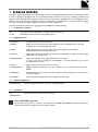
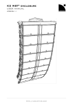
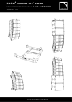
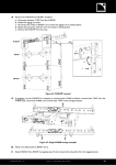
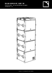
K2 WST enclosure ® RIGGING MANUAL VERSION 1.0 K2_RM_EN_1.0 www.l-acoustics.com 1 / 52 K2 WST® enclosure RIGGING MANUAL VERSION 1.0 SAFETY INSTRUCTIONS 1. Read this manual 2. Follow all SAFETY INSTRUCTIONS as well as DANGER and OBLIGATION warnings 3. Never incorporate equipment or accessories not approved by L-ACOUSTICS® 4. Read all the related PRODUCT INFORMATION documents before exploiting the system The product information document is included in the shipping carton of the related system component. 5. Work with qualified personnel for rigging the system Installation should only be carried out by qualified personnel that are familiar with the rigging techniques and safety recommendations outlined in this manual. 6. Ensure personnel health and safety During installation and set-up personnel must wear protective headgear and footwear at all times. Under no circumstances personnel is allowed to climb on a loudspeaker assembly. 7. Respect the Working Load Limit (WLL) of third party equipment L-ACOUSTICS® is not responsible for any rigging equipment and accessories provided by third party manufacturers. Verify that the Working Load Limit (WLL) of the suspension points, chain hoists and all additional hardware rigging accessories is respected. 8. Respect the maximum configurations and the recommended safety level For safety issue, respect the maximum configurations outlined in this manual. To check the conformity of any configuration in regards with the safety level recommended by L-ACOUSTICS®, model the system in SOUNDVISION and refer to the warnings in Mechanical Data section. 9. Be cautious when flying a loudspeaker array Always verify that no one is standing underneath the loudspeaker array when it is being raised. As the array is being raised, check each individual element to make sure that it is securely fastened to the adjacent element. Never leave the array unattended during the installation process. As a general rule, L-ACOUSTICS® recommends the use of safety slings at all times. 10. Be cautious when ground-stacking a loudspeaker array Do not stack the loudspeaker array on unstable ground or surface. If the array is stacked on a structure, platform, or stage, always check that the latter can support the total weight of the array. As a general rule, L-ACOUSTICS® recommends the use of safety straps at all times. 11. Take into account the wind effects on dynamic load When a loudspeaker assembly is deployed in an open air environment, wind can produce dynamic stress to the rigging components and suspension points. If the wind force exceeds 6 bft (Beaufort scale), lower down and/or secure the loudspeaker array. SYMBOLS The following symbols are used in this document: DANGER This symbol indicates a potential risk of harm to an individual or damage to the product. It can also notify the user about instructions that must be strictly followed to ensure safe installation or operation of the product. OBLIGATION This symbol notifies the user about instructions that must be strictly followed to ensure proper installation or operation of the product. EQUIPMENT This symbol indicates the equipment, tools, and spare parts required to perform a procedure. INFORMATION This symbol notifies the user about complementary information or optional instructions. K2_RM_EN_1.0 www.l-acoustics.com 2 / 52 WELCOME TO L-ACOUSTICS® Thank you for choosing the L-ACOUSTICS® K2 WST® system. This document contains essential information on rigging the system properly and safely. Carefully read this document in order to become familiar with these procedures. As part of a continuous evolution of techniques and standards, L-ACOUSTICS® reserves the right to change the specifications of its products and the content of its documents without prior notice. Please check the L-ACOUSTICS® web site on a regular basis to download the latest document and software updates: www.l-acoustics.com. K2 WST® SYSTEM The L-ACOUSTICS® K1 system has achieved international recognition and is today the prime choice of engineers for the largest stadium tours and outdoor festivals. Its sonic performance, its fully integrated system package and its rider friendliness are considered as the industry benchmarks. With K2, L-ACOUSTICS® offers K1 performance in a rescaled package. The K2 system flexibility makes it suited to both permanent installation and touring applications, from theatre to stadium productions. The main system components are as follows: • • • • K2, full-range element, with adjustable horizontal directivity, operating from 35 Hz to 20 kHz K1-SB, low-frequency element, reinforcing LF contour down to 30 Hz or LF throw down to 35 Hz SB28, low-frequency element, extending the operating bandwidth down to 25 Hz LA4X/LA8 amplified controllers or LA-RAK, touring rack fitted with three LA8 The 3-way quad amplified design, the transducers resources are among the characteristics giving K2 an exceptional ability to perform in many applications and with a record-breaking performance/weight ratio. Any on-site deployment can be easily and quickly achieved thanks to an extremely ergonomic, fast and captive rigging system. A K2 line source utilizes the unrivalled characteristics of Wavefront Sculpture Technology®. Inter-element angles can be set with laser like accuracy up to a generous 10˚, allowing the optimization of the vertical coverage with SPL smoothly spread across the audience. Horizontally, the K2 coverage pattern can be adjusted to sector and match any audience or specific room geometries. Four different settings are possible: two symmetric (70° or 110°) and two asymmetric (90° as 35°/55° or 55°/35°). Thanks to its full range capability, the K2 enclosure can be deployed as a standalone line source. For applications demanding extreme LF impact (contour mode), or maximized LF projection (throw mode), K2 can be arrayed with its dedicated and flyable K1-SB LF extension. The K2 system can also address applications with demanding infrasonic reproduction when combined to the SB28 subwoofer. Before installation, any system configurations can be acoustically and mechanically modeled with SOUNDVISION 3D simulation software. For touring applications, K2 can be associated to the LA-RAK, a universal distribution platform for power, audio signals and network which facilitates cross rental between rental companies. LA-RAK houses three LA8 amplified controllers and can be flown onto a K2 array. Other applications can feature LA8 amplified controllers. For high-end installation projects, K2 can also be driven by the LA4X amplified controller. The scheme authorizes fully discrete DSP treatment per section and maximum power headroom for the best possible sonic performance. Thanks to dedicated factory presets, the LA8/LA4X amplified controller constitutes an extremely advanced and precise drive system for the enclosures. All L-ACOUSTICS® amplified controllers feature the L-DRIVE, a thermal and overexcursion protection circuit. Up to 253 LA8/LA4X amplified controllers can be connected together via the Ethernet-based L-NET protocol. The LA NETWORK MANAGER software allows online remote control and monitoring of all the connected units, via a userfriendly and intuitive graphic interface, and features the Array Morphing EQ. This exclusive tool allows the engineer to quickly adjust the tonal balance of the system to reach a reference curve or to ensure consistency of the sonic signature. K2_RM_EN_0.5 www.l-acoustics.com 3 / 52 K2 WST® enclosure RIGGING MANUAL VERSION 1.0 CONTENTS 1 RIGGING SYSTEM 5 1.1 Loudspeaker enclosure ............................................................................................................................................................... 5 1.2 Rigging elements.......................................................................................................................................................................... 5 1.3 Software application .................................................................................................................................................................... 5 1.4 Accessories.................................................................................................................................................................................. 5 2 MECHANICAL SAFETY 2.1 Mechanical limits ......................................................................................................................................................................... 7 2.2 Assessing mechanical safety ......................................................................................................................................................... 7 3 RIGGING SYSTEM DESCRIPTION 3.1 Elements for enclosure rigging .................................................................................................................................................... 8 3.2 Elements for storage and transportation ..................................................................................................................................... 9 3.3 Elements for flying ..................................................................................................................................................................... 10 3.4 Elements for LA-RAK rigging ..................................................................................................................................................... 12 4 SYSTEM SETUP 4.1 Ground-stacking ........................................................................................................................................................................ 14 4.2 Flying ......................................................................................................................................................................................... 15 5 SUBSET PROCEDURES 7 8 14 17 PROCEDURE A. Preparing a block of 4 K2 ..................................................................................................................................... 17 PROCEDURE B. Preset the inter-enclosure angles......................................................................................................................... 19 PROCEDURE C. Stacking K2 on K2-BUMP .................................................................................................................................... 20 PROCEDURE D. Attaching K2-BAR on K2-BUMP .......................................................................................................................... 23 PROCEDURE E. Attaching a block of four K2 under K2-BUMP ..................................................................................................... 25 PROCEDURE F. Attaching a block of four K2 under K2 ................................................................................................................. 27 PROCEDURE G. Attaching a block of four K2 under a K1 system element .................................................................................... 31 PROCEDURE H. Attaching K1 or K1-SB under K2-BUMP ............................................................................................................. 36 PROCEDURE I. Stacking LA-RAK on K2-BUMP ............................................................................................................................ 37 APPENDIX A: PICKUP POINTS GUIDELINES 41 APPENDIX B: INSTALLING A LASER INCLINOMETER 45 APPENDIX C: SPECIFICATIONS 46 K2 .................................................................................................................................................................................................. 46 K1-SB .................................................................................................................................................................................................. 47 K2-BUMP .............................................................................................................................................................................................. 48 K2-BUMP-FLIGHT................................................................................................................................................................................ 48 K2-BAR ................................................................................................................................................................................................. 49 K2-LINK ................................................................................................................................................................................................ 49 K2-RACKMOUNT ................................................................................................................................................................................ 50 K1-DELTA............................................................................................................................................................................................. 51 K2-CHARIOT........................................................................................................................................................................................ 51 K2_RM_EN_1.0 www.l-acoustics.com 4 / 52 1 RIGGING SYSTEM The system approach developed by L-ACOUSTICS® consists in providing packaged solutions for loudspeaker systems in order to guarantee the highest and most predictable level of performance at any step: modeling, installation, and operation. An L-ACOUSTICS® loudspeaker system is the set of components available to form any loudspeaker system based on one of the full-range loudspeaker enclosures afforded by L-ACOUSTICS®. It includes enclosures, rigging accessories, loudspeaker cables, amplified controllers and software applications. The main components involved in the rigging process of a K2 system are the following: 1.1 Loudspeaker enclosure K2 Full range enclosure, deployable in a variable curvature line source. K1-SB Dedicated subwoofer enclosure, deployable with K2. 1.2 Rigging elements K2-CHARIOT Transport dolly for four K2 enclosures. K2-BUMP Rigging frame used to fly K2 line arrays. Designed to be compatible with K1 and K1-SB. Provided with two bow shackles WLL 3.25 t. K2-BAR Rigging bar designed to provide a wider range of site angles for the K2-BUMP. Provided with two bow shackles WLL 3.25 t. K1-DELTA Rigging plate designed to be used optionally with the K2-BUMP, to adjust the azimuth angle of flown K2 / K1 / K1-SB arrays. K2-BUMPFLIGHT Flight-case dedicated to the rigging elements of the K2 system. In order to be used as storage for the K2-BUMP it must be prepared using the foams provided with the product. K2-LINK Rigging interface between K2 and K1 or K1-SB. K2-RACKMOUNT Rigging interface for stacking one or two LA-RAK on top of a K2 array flown with a K2BUMP. K2-BPCHAIN Adjustable sling used to prevent the chain bag of a climbing hoist being in front of a flown array top enclosure. LA-SLING2T Chain sling with two-leg bridles used to implement bridle hangs. 1.3 Software application SOUNDVISION 1.4 Proprietary 3D acoustical and mechanical modeling software. Accessories K2CHARIOTCOV Protective cover for transportation and storage Other K2 SYSTEM components All the other components of the system are presented in the K2 user manual, document intended to describe the enclosure configurations and connection scheme. K2_RM_EN_0.5 www.l-acoustics.com 5 / 52 K2 WST® enclosure RIGGING MANUAL VERSION 1.0 K2 K1-SB LA-RAK K2-BUMP K2-BAR K2-LINK K2-RACKMOUNT LA-SLING2T K1-DELTA K2-CHARIOT K2-BPCHAIN SOUNDVISION Main components involved in the K2 rigging process K2_RM_EN_1.0 www.l-acoustics.com 6 / 52 2 MECHANICAL SAFETY 2.1 Mechanical limits The K2 rigging system complies with 2006/42/EC: Machinery Directive. It has been designed following the guidelines of BGV-C1. 2006/42/EC: Machinery Directive specifies a safety factor of 4:1 against the rupture. The limits specified in the tables below correspond to deployments with a safety factor of 4:1 or higher. Refer to SOUNDVISION for the safety factor of a specific deployment. The safe limit gives the maximum number of elements for which the safety factor is always compliant with the 2006/42/EC: Machinery Directive, regardless of the other deployment parameters (site angles, inter-enclosure angles, etc.). The maximum limit gives the maximum number of elements for which the safety factor can be compliant with the 2006/42/EC: Machinery Directive, when the other deployment parameters provide the best mechanical conditions. Ground-stacked K2 on K1-SB with K2-BUMP Flown K2-BUMP K2-BUMP + K2-BAR K2-LINK under K1-BUMP Safe limit Maximum limit 4 K2 6 K2 Safe limit Maximum limit 16 K2 24 K2 24 K2 + 2 LA-RAK 14 K2 + 2 LA-RAK 12 K1-SB + 1 LA-RAK 16 K1-SB + 2 LA-RAK 16 K2 24 K2 SOUNDVISION and mechanical safety To deploy more elements than the safe limits, or when mixing different type of loudspeaker enclosures within the same array, always model the system in SOUNDVISION before installation, and check the Mechanical Data section for any stress warning or stability warning. 2.2 Assessing mechanical safety In order to assess the actual safety of any array configuration before implementation, refer to the following warnings: Rated working load limit (WLL) is not enough The rated WLL is an indication of the element resistance to tensile stress. For complex mechanical systems such as loudspeaker arrays, WLLs cannot be used per se to determine the maximum number of enclosures within an array or to assess the safety of a specific array configuration. Mechanical modeling with SOUNDVISION The working load applied to each linking point, along with the corresponding safety factor, will depend on numerous variables linked to the composition of the array (type and number of enclosures, splay angles) and the implementation of the flying or stacking structure (number and location of flying points, site angle). This cannot be determined without the complex mechanical modeling and calculation offered by SOUNDVISION Assessing the safety with SOUNDVISION The overall safety factor of a specific mechanical configuration always corresponds to the lowest safety factor among all the linking points. Always model the system configuration with the SOUNDVISION software and check the Mechanical Data section to identify the weakest link and its corresponding working load. By default, a stress warning will appear when the mechanical safety goes beyond the recommended safety level. Safety of ground-stacked arrays in SOUNDVISION For ground-stacked arrays, a distinct stability warning is implemented in SOUNDVISION. It indicates a tipping hazard when the array is not secured to the ground, stage or platform. It is user responsibility to secure the array and to ignore this warning. Consideration must be given to unusual conditions SOUNDVISION calculations are based on usual environmental conditions. A higher safety factor is recommended with factors such as extreme high or low temperatures, strong wind, prolonged exposition to salt water, etc. Always consult a rigging specialist to adopt safety practices adapted to such a situation. K2_RM_EN_0.5 www.l-acoustics.com 7 / 52 K2 WST® enclosure RIGGING MANUAL VERSION 1.0 3 RIGGING SYSTEM DESCRIPTION K2 enclosures can be ground-stacked and flown independently (K2-BUMP) or in combination with K1 system elements (K1, K1-SB, or K1-BUMP). The K2-BUMP is designed to be directly compatible with K1 and K1-SB. The K2 enclosure rigging system requires the K2-LINK interface to be compatible with the K1 rigging system. 3.1 Elements for enclosure rigging On both sides, the K2 enclosure integrates two arms to connect to another element of the rigging system, such as an enclosure or to a flying frame. At the front, a rotating arm provides a fixed point around which the enclosure can freely rotate until its connection at the rear. At the rear, a sliding arm allows the inter-element angle setting and the inter-element rear connection. The angles between adjacent enclosures are secured by an automatic system that is activated in advance and locks itself during the stacking and lifting procedures. K2_RM_EN_1.0 www.l-acoustics.com 8 / 52 3.2 Elements for storage and transportation The K2-CHARIOT is designed for the transportation and storage of blocks of four K2 enclosures. During transportation the blocks must have an inter-enclosure angle of 10° to avoid any separation of the enclosures. This angle must be set using the enclosure rear rigging arm pin. The automatic locking system must remain unloaded. The K2-CHARIOT rear rigging arm must be at its -15° site angle position. TIPPING HAZARD If the enclosures are not pinned at 10°, they can separate at the back, causing the stack to tip over. K2_RM_EN_0.5 www.l-acoustics.com 9 / 52 K2 WST® enclosure RIGGING MANUAL VERSION 1.0 3.3 Elements for flying The K2-BUMP is designed for flying line arrays of K2, K1 or K1-SB enclosures. 4 holes are available on the central bar of the K2-BUMP. Refer to your SOUNDVISION model to know which holes to use. With K1-SB and a single motor the hole no 2 provides a 0° site angle. By adding a K2-BAR to the K2-BUMP, the site angle range can be increased. 21 holes are available on the K2-BAR which can be attached to the K2-BUMP as a rear or a front extension and in position A or B, thus offering a total of 84 discrete positions for pick-up points. The rear extension is suited to downwards and front extension to upwards site angles. K2_RM_EN_1.0 www.l-acoustics.com 1 0 / 52 Standard: One K2-BAR attached in the center of K2-BUMP Alternative: Two K2-BAR attached on the sides The K2 system can be flown under a K1 system element, K1, K1-SB or K1-BUMP. The K2-LINK is designed to make the rigging systems compatible. It provides three holes and therefore three angles between the top K2 enclosure and the bottom K1 element: 0.25°, 2.5° and 5°. K2_RM_EN_0.5 www.l-acoustics.com 1 1 / 52 K2 WST® enclosure RIGGING MANUAL VERSION 1.0 3.4 Elements for LA-RAK rigging The K2-RACKMOUNT is designed to stack one or two LA-RAK on top of a flown array. It is composed of four rails and a stabilizer. The rails are screwed on the K2-BUMP. Their number and position depend on the number of racks. The K2-RACKMOUNT must be used along with either one or two K2-BAR. 1 LA-RAK : 2 rails : 2 K2-BAR K2_RM_EN_1.0 2 LA-RAK : 4 rails : 1 K2-BAR www.l-acoustics.com 1 2 / 52 When two racks are mounted side by side, the stabilizer is used to prevent the assembly from tipping or toppling over. The stabilizer traps one of the chains used to lift the assembly. 0° site angle 30° positive site angle Refer to APPENDIX A: PICKUP POINTS GUIDELINES for more information. K2_RM_EN_0.5 www.l-acoustics.com 1 3 / 52 K2 WST® enclosure RIGGING MANUAL VERSION 1.0 4 SYSTEM SETUP 4.1 Ground-stacking Final check After the setup, always verify no yellow labels are visible on the front and on both sides of the array. K2 enclosures on K1-SB Stack as many K1-SB enclosures as necessary. Refer to the K1 rigging manual to set up the K1-SB part of the array. Position and attach a K2-BUMP on the K1-SB stack Refer to PROCEDURE H. Position and attach an upside down K2 on the K2-BUMP and add as many K2 enclosures on top of the first one. Refer to PROCEDURE C. K2_RM_EN_1.0 www.l-acoustics.com 1 4 / 52 4.2 Flying Final check After the setup, always verify no yellow labels are visible on the front and on both sides of the array. At least one motor for each K2-BAR When using two K2-BAR, do not implement a bridle between the bars. Before setup, choose a flying option Refer to SOUNDVISION modeling and to 3.3 Elements for flying (p. 2). K2 enclosures under K2-BUMP Prepare all the blocks of 4 K2 necessary to build the array. If a block is not already built, refer to PROCEDURE A. Preset the inter-enclosures angles. Refer to PROCEDURE B. Place an open a K2-BUMPFLIGHT under the motor. If necessary, attach one or two K2-BAR to the K2-BUMP. Refer to PROCEDURE D. If necessary, stack one or two LA-RAK on the K2-BUMP. Refer to PROCEDURE I. Refer to APPENDIX A: when stacking only one LA-RAK. Attach the shackles. Refer to SOUNDVISION for the number and position of the shackles. Lift the assembly so you can position a block of four K2 under it. Attach the block of four K2 to the K2-BUMP Refer to PROCEDURE E. Verify that the rear rigging arms are secured by pins and that no yellow label is visible on the front. Lift the assembly so you can position a block of four K2 under it. Verify that no yellow label is visible on both sides of the array. Attach the block of four K2 enclosures to the bottom of the array. Refer to PROCEDURE F. Verify that the rigging arms at the back are secured by pins and that no yellow label is visible on the front. Repeat the last two steps until the array is complete. Raise the array to its final trim height. Adjust site and azimuth angles. K2_RM_EN_0.5 www.l-acoustics.com 1 5 / 52 K2 WST® enclosure RIGGING MANUAL VERSION 1.0 Final check After the setup, always verify no yellow labels are visible on the front and on both sides of the array. When using two K2-BAR, do not implement a bridle between the bars. Always use at least two motors. Refer to APPENDIX A: PICKUP POINTS GUIDELINES. Before setup, choose a flying option Refer to SOUNDVISION modeling and to 3.3 Elements for flying (p. 2). K2 enclosures under K1-SB K1-SB array setup Refer to your SOUNDVISION model to define which flying frame to use. If you are using the K1-BUMP: Refer to the K1 rigging manual to set up the K1-SB part of the array. Or if you are using the K2-BUMP: Place an open a K2-BUMPFLIGHT under the motor. If necessary, attach one or two K2-BAR to the K2-BUMP. Refer to PROCEDURE D. If necessary, stack one or two LA-RAK on the K2-BUMP. Refer to PROCEDURE I. Refer to APPENDIX A: when stacking only one LA-RAK. Attach the shackles. Refer to SOUNDVISION for the number and position of the shackles. Lift the assembly so you can position a block of K1-SB under it. Attach the K1-SB block to the K2-BUMP. Refer to PROCEDURE H. Repeat the last two steps until the K1-SB array is complete. K2 array setup Prepare all the blocks of 4 K2 necessary to build the array If a block is not built already, refer to PROCEDURE A. Preset the inter-enclosures angles. Refer to PROCEDURE B. K1-SB and K2 arrays connection Lift the K1-SB array so you can position a block of four K2 under it. Using two K2-LINK interfaces, attach the block of K2 under the K1-SB array. Refer to PROCEDURE G. Verify that the rear rigging arms are secured by pins and that no yellow label is visible on the front. Lift the array so you can position a block of four K2 under it. Verify that no yellow label is visible on both sides of the array. Attach the block of four K2 to the bottom enclosure of the array. Refer to PROCEDURE F. Verify that the rear rigging arms are secured by pins and that no yellow label is visible on the front. Repeat the last two steps until the array is complete. Raise the array to its final trim height. Adjust site and azimuth angles. K2_RM_EN_1.0 www.l-acoustics.com 1 6 / 52 5 SUBSET PROCEDURES PROCEDURE A. Preparing a block of 4 K2 1. Attach a K2 enclosure on K2-CHARIOT. Fully rotate the rear rigging arms of the K2-CHARIOT. Position the K2 enclosure on the K2-CHARIOT dolly Lift the rear of the enclosure and rotate the dolly rear rigging arm in its upward position. K2_RM_EN_0.5 Secure the enclosure at the front using the LINK hole. Secure the enclosure using the LINK hole. www.l-acoustics.com 1 7 / 52 K2 WST® enclosure RIGGING MANUAL VERSION 1.0 2. Attach the other K2 enclosures on top of each other until the block of four is complete. While holding the handle, rotate the front rigging arm and secure it with both LINK pins. Position a K2 enclosure on the first one. Slide the rear rigging arm and secure it with both pins, in the LINK and 10° holes. Keep holding the enclosure in position with the handles until the front rigging arm is secured. 3. Make sure the automatic locking system button is unloaded . If the button has been pressed, pull to disengage the latch K2_RM_EN_1.0 www.l-acoustics.com 1 8 / 52 PROCEDURE B. Preset the inter-enclosure angles On both sides: Remove the pin from its current angle hole Position the pin at the chosen angle hole and slide the rigging arm until the pin goes in. Press the lock button K2_RM_EN_0.5 www.l-acoustics.com 1 9 / 52 K2 WST® enclosure RIGGING MANUAL VERSION 1.0 PROCEDURE C. 1. Stacking K2 on K2-BUMP Prepare the K2 block top enclosure and turn it upside down on the K2-BUMP. Define the K2 line site angle with the rear rigging arm. Take out and lock the rear and front rigging arms. Select a value between 0.25 and 7.5 and substract 3 to obtain the final site angle. Remove the lower rear and front pins. K2_RM_EN_1.0 www.l-acoustics.com 2 0 / 52 2. Secure the K2 enclosure on the K2-BUMP. The rigging arms should rest of the K2-BUMP spacers. Secure the front and rear rigging arm to the K2-BUMP. Slide the front rigging arm up and down to align the holes. Secure the front rigging arm to the K2 enclosure. Raise the enclosure to align the holes. Push the locking system button to unblock the lock. 3. Prepare the K2 block top enclosure Adjust the inter-enclosure angle with the rear rigging arm. Remove the lower front and rear pins. K2_RM_EN_0.5 www.l-acoustics.com 2 1 / 52 K2 WST® enclosure RIGGING MANUAL VERSION 1.0 4. Turn the K2 enclosure upside down, lower it and secure it on the other K2. Secure the front and rear rigging arm to the lower K2 enclosure. Secure the front and rear rigging arm to the K2-BUMP. Slide the front rigging arm up and down to align the holes. 5. K2_RM_EN_1.0 Secure the front rigging arm to the top enclosure. Raise the top enclosure to align the holes. Push the locking system button to unblock the lock. Repeat steps 3 to 5 until the line is complete. www.l-acoustics.com 2 2 / 52 PROCEDURE D. 1. K2_RM_EN_0.5 Attaching K2-BAR on K2-BUMP Refer to your SOUNDVISION model to identify the extension and position of the bar. www.l-acoustics.com 2 3 / 52 K2 WST® enclosure RIGGING MANUAL VERSION 1.0 2. Remove the pins and motor. K2_RM_EN_1.0 lift the K2-BAR using the 3. Turn the K2-BUMP-FLIGHT 90°, lower the K2-BAR and pin it according to the chosen flying option (position A or B, in front or rear extension) www.l-acoustics.com 2 4 / 52 PROCEDURE E. Attaching a block of four K2 under K2-BUMP 1. Lower the K2-BUMP to allow for front connection. 2. Attach the front rigging arm on both sides. Rotate the arm and secure it with the K2-BUMP pin. Preset inter-enclosure angles Preset the K2 inter-enclosure angles before performing this procedure. Refer to PROCEDURE B. Lower the K2-BUMP and secure the connection with the K2 pin. If you cannot insert the pin, move the frame back and fortt. 3. Lower the rear of the K2-BUMP. 4. Attach the rear rigging arm to the frame. Slide the arm to its 5° position. Secure the arm with the frame pin. Preset the angle at 5° with the enclosure pin. Do not lower until contact. Leave a gap allowing to slide the K2 arm to its 5° position. K2_RM_EN_0.5 www.l-acoustics.com 2 5 / 52 K2 WST® enclosure RIGGING MANUAL VERSION 1.0 5. Raise the array to lock the enclosures 6. Remove the K2-CHARIOT Hold the dolly with one hand. Remove the back pin on both sides. Hold the dolly with one hand. Remove the front pin on both sides. K2_RM_EN_1.0 www.l-acoustics.com 2 6 / 52 PROCEDURE F. Attaching a block of four K2 under K2 7. Attach the front rigging arm on both sides. Preset inter-enclosure angles Rotate the arm to align its hole with the K2 rigging hole. Preset the K2 inter-enclosure angles before performing this procedure. Refer to PROCEDURE B. Pin the arm in the LINK hole of the flown array. Lower the flown array and secure the assembly with the LINK pin. If you cannot insert the pin, move the flown array back and forth with enclosure handle. K2_RM_EN_0.5 www.l-acoustics.com 2 7 / 52 K2 WST® enclosure RIGGING MANUAL VERSION 1.0 8. Lock the inter-enclosure angles of the block Raise the array. K2_RM_EN_1.0 The lower K2 enclosures swing and the latches automatically lock. www.l-acoustics.com 2 8 / 52 9. Attach the lower K2 enclosures rear rigging arm to the back of the array. Turn the wheels inside the dolly. Pull back the bottom enclosures while lowering the array until the array and the top enclosure of the block are in contact. Slide the arm upward and secure it with the pin using the LINK hole. Position the pin at the entrance of the chosen angle hole and slide the rigging arm until the pin goes in. Press the lock button K2_RM_EN_0.5 www.l-acoustics.com 2 9 / 52 K2 WST® enclosure RIGGING MANUAL VERSION 1.0 10. Raise the array to lock the inter-enclosure angle. The latches automatically lock. 11. Remove the K2-CHARIOT Hold the dolly with one hand. Remove the back pin on both sides. Hold the dolly with one hand. Remove the front pin on both sides. K2_RM_EN_1.0 www.l-acoustics.com 3 0 / 52 PROCEDURE G. Attaching a block of four K2 under a K1 system element 1. Preset inter-enclosure angles Preset the K2 inter-enclosure angles before performing this procedure. Refer to PROCEDURE B. Attach the front rigging arm on both sides. Rotate the arm to align its hole with the K1/K1-SB rigging hole. Pin the arm on the flown array. Lower the flown array and secure the assembly with the LINK pin. If you cannot insert the pin, move the flown array back and forth with enclosure handle. K2_RM_EN_0.5 www.l-acoustics.com 3 1 / 52 K2 WST® enclosure RIGGING MANUAL VERSION 1.0 2. Lock the inter-enclosure angles. Raise the array. K2_RM_EN_1.0 www.l-acoustics.com 3 2 / 52 3. Attach the K2-LINK interfaces to the K1/K1-SB. Turn the wheels inside the dolly. Pull back the bottom enclosures while lowering the array until only the front wheel touches the ground . On both sides, attach a K2-LINK at the back of the K1-SB enclosure. Do not pin K2-LINK on K2. K2_RM_EN_0.5 www.l-acoustics.com 3 3 / 52 K2 WST® enclosure RIGGING MANUAL VERSION 1.0 4. Attach the K2-LINK to the K2 enclosure. Lower the array Push the K2-LINK to guide it into the K2 rigging. Secure the K2-LINK on the K2 rigging middle hole. 5. K2_RM_EN_1.0 www.l-acoustics.com 3 4 / 52 5. Remove the K2-CHARIOT Raise the array Hold the dolly with one hand. Remove the back pin on both sides. Hold the dolly with one hand. Remove the front pin on both sides. K2_RM_EN_0.5 www.l-acoustics.com 3 5 / 52 K2 WST® enclosure RIGGING MANUAL VERSION 1.0 PROCEDURE H. Attaching K1 or K1-SB under K2-BUMP 1. Slide out K1-SB front rigging arm and pin it at 0° on both sides. 2. Attach the K2-BUMP to the K1 elements block. Remove the K2-BUMP rear and front pins on both sides. Lower the K2-BUMP so it rest on the topmost enclosure. Rotate the rear rigging arm and pin it on the frame. Pin the front rigging arm on the frame. K2_RM_EN_1.0 www.l-acoustics.com 3 6 / 52 PROCEDURE I. Stacking LA-RAK on K2-BUMP Tools Electric screwdriver with torque selector. 6 mm hex bit. Wrench with 13 mm hex socket. 1. Remove the nuts and bolts from the K2-RACKMOUNT rails. 2. Position and secure as many rails as necessary on the K2-BUMP. 1 LA-RAK 2 LA-RAK 3. Secure the rails on the K2-BUMP. Use the wrench with a 13 mm hex socket and the electric screwdriver. Set the torque to 5 N.m. Before securing the side rails, make sure the frame pins are on the outside. K2_RM_EN_0.5 www.l-acoustics.com 3 7 / 52 K2 WST® enclosure RIGGING MANUAL VERSION 1.0 4. Install as many K2-BAR as necessary. When installing a single K2-BAR at the center of the frame, make sure the pins are inserted between the central bar of the frame and the closest rail. K2_RM_EN_1.0 www.l-acoustics.com 3 8 / 52 5. Attach the LA-RAK on the K2-BUMP. Remove the LA-RAK coupling bars Turn the bars to release the spring-loaded safety and slide them out. Position the LA-RAK on the rails. Secure the LA-RAK with the coupling bars. Insert the spring-loaded safety in the LA-RAK rails, give a quarter turn and slide the bar until the safety locks into place. Insert the coupling bars: from the back for a negative angle (rear extension), from the front for a positive angle (front extension). Always insert so the metallic safety is pointed upward (depending on the tilt angle). K2_RM_EN_0.5 www.l-acoustics.com 3 9 / 52 K2 WST® enclosure RIGGING MANUAL VERSION 1.0 6. If you are stacking 2 LA-RAK side-by-side on K2-BUMP, insert the stabilizer between the two racks. Release the locking system by raising and turning the handle. Insert the stabilizer on the side opposite to the K2-BAR: from the front in rear extension from the rear in front extension. Secure the stabilizer by locking the handle. K2_RM_EN_1.0 www.l-acoustics.com 4 0 / 52 APPENDIX A: PICKUP POINTS GUIDELINES A K2 system can be lifted using one or two motors: One or two motors with K2-BUMP alone. Two motors with K2-BUMP and one K2-BAR. Two with K2-BUMP and two K2-BAR. K2-BUMP with LA-RAK OK NOT OK OK With a single LA-RAK on top of a K2-BUMP, always implement a bridle suspension using two LA-SLING2T. K2_RM_EN_0.5 www.l-acoustics.com 4 1 / 52 K2 WST® enclosure RIGGING MANUAL VERSION 1.0 Use two LA-SLING2T to implement bridle hangs. Specifications Lifting chain (DIN EN 818-4) Steels grade Nominal length incl. hooks Maximum sling angle βmax Load rating 2-leg , 8 mm 8 1 m / 39.4 in 60° 2.8 t for β : 0° - 45° 2t for β : 46° - 60°) Never use slings shorter that 1 m (39.4 in). One leg of the LA-SLING2T must always be connected to the K2-BAR hole no 1 (i.e., the closest to the array). The other leg can be connected to holes no 11 to no 21. Refer to your SOUNDVISION simulation to choose the hole. K2_RM_EN_1.0 www.l-acoustics.com 4 2 / 52 K2-BUMP with no LA-RAK OK NOT OK With two K2-BAR on a K2-BUMP, do not implement a bridled suspension Do not implement a bridled between the two bars. suspension on a single K2-BAR. K2_RM_EN_0.5 www.l-acoustics.com 4 3 / 52 K2 WST® enclosure RIGGING MANUAL VERSION 1.0 K1-DELTA for azimuth control To control the azimuth of a flown K2 line, attach the K1-DELTA to the rear pickup point. The recommended space between the two lifting point is 1 m / 33 ft. By adjusting the height of both pickup points you can adjust the azimuth angle from -10° to +10°. K2-BPCHAIN with a climbing hoist With a climbing hoist you must use a K2-BPCHAIN adjustable sling to prevent the chain bag from hanging in front of the top enclosures of the array. Electric chain hoists K2_RM_EN_1.0 Climbing hoists www.l-acoustics.com 4 4 / 52 APPENDIX B: INSTALLING A LASER INCLINOMETER The K2 rigging system is compatible with the following laser inclinometers: TEQSAS® LAP-TEQ (part of the L-ACOUSTICS® TECH TOOLCASE) SSE® ProSight TEQSAS® LAP-TEQ XLR 3 cable T20 Torx key Medium-strength thread-locker (blue) 1. 2. 3. Remove the four M4 Torx screws (T20) from the plate. Put thread-locker in the four threaded inserts. Position the LAP-TEQ so it points toward the front of the K2-BUMP. 4. 5. Secure the LAP-TEQ with the four screws. Connect the XLR 3 cable to the sensor. 6. Follow the manufacturer instructions to calibrate the inclinometer. K2_RM_EN_0.5 www.l-acoustics.com 4 5 / 52 K2 WST® enclosure RIGGING MANUAL VERSION 1.0 APPENDIX C: SPECIFICATIONS K2 Description 3-way active enclosure, quad-amplified by LA4X or LA8 Usable bandwidth (-10 dB) 35 Hz - 20 kHz ([K2_70] preset) Maximum SPL1 145 dB ([K2_70] preset) Horizontal : 110° / 70° symmetric 90° asymmetric (35° / 55° or 55° / 35°) Vertical : dependent upon number of elements and array curvature Coverage angle (-6 dB) LF: 2 12", weather-resistant , bass-reflex MF: 4 6.5", weather-resistant , bass-reflex Transducers HF: 2 3", diaphragm compression driver, DOSC® waveguide Nominal impedance LF = 2 8 Ω, MF = 8 Ω, HF = 16 Ω LF: 450 W RMS power handling MF: 320 W HF: 160 W Connectors Rigging components IN: 1 8-point PA-COM® LINK: 1 8-point PA-COM® Captive 4-point rigging system Inter-enclosure angles: 0.25°, 1°, 2°, 3°, 4°, 5°, 7.5° or 10° Dimensions Physical data Weight (net): 56 kg / 123.2 lb Cabinet: first grade Baltic birch plywood Finish: Protection Rating: Dark Grey brown (proprietary color) Pure white RAL 9010® Steel grill with polyester anti-corrosion coating Airnet® acoustically neutral fabric IP45 Rigging component: High grade steel with polyester anti-corrosion coating Front: 1 Peak level at 1 m under half-space conditions using 10 dB crest factor pink noise with specified preset. K2_RM_EN_1.0 www.l-acoustics.com 4 6 / 52 K1-SB Description Subwoofer enclosure, amplified by LA8 Low frequency limit (‑10 dB) Maximum SPL 1 34 Hz ([K1SB_X] preset) 143 dB ([K1SB_X] preset) RMS power handling Transducer Nominal impedance Connectors Rigging components2 1200 W 2 15" , weather-resistant, bass-reflex 4" coil, magnesium die-cast basket, vented magnet design 4Ω IN: 1 4-point SpeakON® Captive 4-point rigging system Inter-enclosure angles: 0°, 0.5°, 1°, 1.5°, 2°, 2.5°, 3°, 4°or 5° Handles integrated in the cabinet Dimensions Weight (net): Cabinet: Protection Rating: Dark Grey brown Pantone 426C Pure white RAL 9010® Steel grill with anti-corrosion coating Airnet® acoustically neutral fabric IP45 Rigging components: High strength steel with anti-corrosion coating Finish: Physical data 83 kg / 183 lb Baltic birch plywood Front: 1 Peak level at 1 m under half-space conditions using 10 dB crest factor pink noise with specified preset. K2_RM_EN_0.5 www.l-acoustics.com 4 7 / 52 K2 WST® enclosure RIGGING MANUAL VERSION 1.0 K2-BUMP Description Rigging frame for K2 enclosure Dimensions Weight 42.3 kg / 93.3 lb Material High-grade steel with anti-corrosion coating. K2-BUMP-FLIGHT Description Flight-case for the K2 system rigging elements. Dimension s Weight K2_RM_EN_1.0 105 kg / 231 lb www.l-acoustics.com 4 8 / 52 K2-BAR Description Rigging bar for K2-BUMP. Dimensions Weight 17 kg / 37.5 lb Material High-grade steel with anti-corrosion coating K2-LINK Description Rigging interface for K2 and K1, K1-SB or K1-BUMP. Dimensions Weight K2_RM_EN_0.5 1.8 kg / 4 lb Material High-grade steel with anti-corrosion coating www.l-acoustics.com 4 9 / 52 K2 WST® enclosure RIGGING MANUAL VERSION 1.0 K2-RACKMOUNT Description Rigging interface for stacking one or two LA-RAK on top of a K2 array flown with a K2-BUMP. Dimensions Weight 3.3 kg / 7.3 lb Description Stabilizer for two LA-RAK side by side on top of a K2 array flown with a K2-BUMP. Material Steel with anti-corrosion coating. Dimensions Weight K2_RM_EN_1.0 2.2 kg / 4. lb Material Steel with anti-corrosion coating. www.l-acoustics.com 5 0 / 52 K1-DELTA Description Rigging element for the K1 system Dimensions Weight Material 9,5 kg / 21 lbs. High-grade steel with anti-corrosion coating K2-CHARIOT Description Transport dolly for the K2 enclosure. Dimensions Weight 50 kg / 110.2 lb K2_RM_EN_0.5 Material Steel with anti-corrosion coating. www.l-acoustics.com 5 1 / 52 K2 WST® enclosure RIGGING MANUAL VERSION 1.0 Document reference: K2_RM_EN_1.0 Distribution date: December 6, 2013 © 2013 L-ACOUSTICS®. All rights reserved. No part of this publication may be reproduced or transmitted in any form or by any means without the express written consent of the publisher. K2_RM_EN_1.0 www.l-acoustics.com 5 2 / 52