1
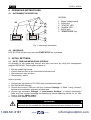
ENGLISH
User’s manual
1.800.561.8187
©Copyright HT ITALIA 2005
www.
.com
[email protected]
Release EN 1.00 - 03/10/2005
XL423 - XL424
INDEX
1. SAFETY PRECAUTIONS AND PROCEDURES .......................................................................................... 2
1.1
1.2
1.3
1.4
Preliminary instructions ......................................................................................................................................... 2
During use............................................................................................................................................................. 3
After use................................................................................................................................................................ 3
Overvoltage categories - definitions...................................................................................................................... 3
2.1
2.2
Introduction ........................................................................................................................................................... 4
Functions .............................................................................................................................................................. 4
3.1
3.2
3.3
3.4
Preliminary checks................................................................................................................................................ 5
Power supply ........................................................................................................................................................ 5
Calibration............................................................................................................................................................. 5
Storage ................................................................................................................................................................. 5
4.1
4.2
Instrument description........................................................................................................................................... 6
Keyboard............................................................................................................................................................... 6
5.1
Date, Time and Measuring Interval ....................................................................................................................... 6
6.1
6.2
6.3
Using the instrument in a Single Phase plant ....................................................................................................... 7
Using the instrument in a Three Phase 4-wires plant............................................................................................ 9
Using the instrument in a Three Phase 3-wires plant.......................................................................................... 11
9.1
9.2
9.3
9.4
General information............................................................................................................................................. 14
Battery replacement............................................................................................................................................ 14
Cleaning.............................................................................................................................................................. 14
End of life ............................................................................................................................................................ 14
2 GENERAL DESCRIPTION ........................................................................................................................... 4
3 PREPARATION FOR USE ........................................................................................................................... 5
4 OPERATING INSTRUCTIONS..................................................................................................................... 6
5 INITIAL SETTINGS....................................................................................................................................... 6
6 MEASURING PROCEDURE ........................................................................................................................ 7
7 LED MESSAGES DESCRIPTION ...............................................................................................................13
8 CONNECTION OF INSTRUMENT TO PC..................................................................................................13
9 MAINTENANCE ..........................................................................................................................................14
10 TECHNICAL SPECIFICATIONS .................................................................................................................15
10.1 Characteristics .................................................................................................................................................... 15
10.1.1 Safety standards...........................................................................................................................................................15
10.1.2 General data .................................................................................................................................................................15
10.2 Environmental conditions .................................................................................................................................... 15
10.2.1 Climatic conditions........................................................................................................................................................15
10.2.2 EMC..............................................................................................................................................................................15
10.3 Accessories......................................................................................................................................................... 16
11 SERVICE .....................................................................................................................................................16
11.1 Warranty conditions ............................................................................................................................................ 16
11.2 After-sale service ................................................................................................................................................ 16
1.800.561.8187
www.
EN.com
-1
[email protected]
XL423 - XL424
1. SAFETY PRECAUTIONS AND PROCEDURES
This meter has been designed in compliance with EN 61010 directive. For your own safety
and to avoid damaging the instrument we suggest you follow the procedures hereby
prescribed and to read carefully all the notes preceded by the symbol .
WARNING
Should you fail to keep to the prescribed instructions you could damage the
instrument and/or its components or endanger your safety.
Take extreme care of the following conditions while taking measurements:
Do not performing any measures in humid or wet environments.
Do not use the meter in presence of explosive gas (material), combustible gas
(material), steam or dust.
Do not touch the circuit under test if no measurement is being taken.
Do not use the instrument if it seems to be malfunctioning (i.e. if you notice
deformations, breaks, leakage of substances and so on).
The herewith symbols are used:
Caution: refer to the instruction manual; an improper use may damage the
instrument or its components
Danger high voltage: risk of electrical shocks
Double insulated meter
AC voltage and current
1.1
PRELIMINARY INSTRUCTIONS
This instrument has been designed for use in environments of pollution degree 2 up to
2000m high.
It can be used for VOLTAGE measurements up to 600V AC on installations with
overvoltage category CAT III 600V~ between the inputs and to ground.
Please use the standard safety precautions aimed at:
Protecting you against dangerous electric currents.
Protecting the instrument against incorrect operations.
Do not test circuits exceeding the voltage limits.
If possible de-energize the plant under test before connecting the instrument. Take all
the safety precautions before taking actions on the plant.
Do not perform any test under environmental conditions exceeding the limits indicated
in this manual (ref. par. 10.2).
Make sure that batteries are correctly installed.
Only the accessories supplied with the instrument guarantee compliance with the
safety standards. They must be in good conditions and must be replaced, if necessary,
with identical models.
1.800.561.8187
www.
EN.com
-2
[email protected]
XL423 - XL424
1.2 DURING USE
Carefully read the herewith recommendations and instructions:
WARNING
•
Non compliance with warnings and/or instructions may cause damage to
the tester or its components or injure the operator.
• During a measurement never touch any unused terminal.
1.3
AFTER USE
If you expect not to use the instrument for a long period of time remove the batteries
and strictly follow the indications at paragraph 9.2.
1.4 OVERVOLTAGE CATEGORIES - DEFINITIONS
EN 61010-1 (Safety requirements for electrical equipment for measurement, control and
laboratory use, Part 1: General requirements) defines what a measurement category
(usually called “overvoltage category”) is. At paragraph 6.7.4: Measuring circuits it says:
(OMISSIS)
Circuits are divided into the following measurement categories:
•
Measurement category IV is for measurements performed at the source of low
voltage installations.
Examples are electricity meters and measurements on primary overcurrent protection devices
and ripple control units.
•
Measurement category III is for measurements performed in the building
installation.
Examples are measurements on distribution boards, circuit breakers, wiring,
including cables, bus-bars, junction boxes, switches, socket-outlets in the fixed
installation, and equipment for industrial use and some other equipment, for
example, stationary motors with permanent connection to fixed installation.
•
Measurement category II is for measurements performed on circuits directly
connected to the low voltage installation.
Examples are measurements on household appliances, portable tools and similar
equipment.
•
Measurement category I is for measurements performed on circuits not directly
connected to MAINS.
Examples are measurements on circuits not derived from MAINS, and specially
protected (internal) MAINS-derived circuits. In the latter case, transient stresses are
variable; for that reason, the norm requires that the transient withstand capability of
the equipment is made known to the user.
1.800.561.8187
www.
EN.com
-3
[email protected]
XL423 - XL424
2 GENERAL DESCRIPTION
2.1 INTRODUCTION
Dear Customer, the instrument you have just purchased will grant you accurate and
reliable measurements provided that it is used according to the present manual’s
instructions.
The instrument was designed to grant the user the utmost safety conditions thanks to a
new concept assuring double insulation and overvoltage CAT III 600V~ between inputs
and to ground.
2.2 FUNCTIONS
This manual is referred to two models: XL423 and XL423. XL423 can recording a single
voltage in single phase or three phase plant. XL424 can recording up to 3 voltages
simultaneously in single phase or three phase plant.
Where not expressly indicated the characteristics are common for both models.
The meter can monitoring a plant for a long time thanks to a sophisticated memorymanaging algorithm. More exactly, the instrument uses the following sampling periods:
Measuring Interval
1s
6s
30s
1min
5min
XL423 – Autonomy (days)
5
34
170
364 (*)
1820 (*)
XL424 – Autonomy (days)
1.5
8
42
91
455 (*)
(*) Depending on batteries autonomy
The instrument starts each recording using the Measuring Interval set through PC
DATALINK software (see chapter 8). Just before the event of full memory, the instrument
applies the successive measuring Interval to all the memory, thus getting more free
memory locations. The instrument continues the data storing according to the new
sampling period.
1.800.561.8187
www.
EN.com
-4
[email protected]
XL423 - XL424
3 PREPARATION FOR USE
3.1
PRELIMINARY CHECKS
This instrument has been checked mechanically and electrically before shipment. All
precautions have been taken to assure that the instrument reaches you in perfect
condition.
However, it is advisable to carry out a rapid check in order to detect any possible damage,
which might have occurred in transit.
Check the accessories contained in the packaging to make sure they are the same as
reported in chapter 11.
3.2 POWER SUPPLY
The instrument is powered by two 1.5V type LR6 AA AM3 MN1500 alkaline batteries. For
battery life see paragraph 10.1.2. For battery fitting operation procedure please see
paragraph 9.2.
WARNING
• The meter, after fitted batteries, is always continuously ON also if STATUS
and ALARM LED are OFF. Pressing of START/STOP key activate or disable
recordings only.
• During a recording the blinking ALARM LED every 3 seconds means a low
battery status.
3.3 CALIBRATION
The instrument complies with the accuracy specifications listed in this manual and such
compliance is guaranteed for 12 months, afterwards the tester may need recalibration.
3.4 STORAGE
In order to guarantee the accuracy of the measurements, after a period of storage in
extreme environmental conditions wait for the instrument to stabilize to within the listed
operating conditions (see paragraph 10.2).
1.800.561.8187
www.
EN.com
-5
[email protected]
XL423 - XL424
4 OPERATING INSTRUCTIONS
4.1
INSTRUMENT DESCRIPTION
LEGEND:
L1
L1
L2
L3
1
2
3
4
1.
2.
3.
4.
5.
6.
Phase Voltage Inputs
COM input
“STATUS" LED
"ALARM" LED
RS232 port
"START/STOP" key
5
6
Fig. 1: Instrument description
4.2 KEYBOARD
LED “STATUS” blinks every time the START/STOP key is pressed.
5 INITIAL SETTINGS
5.1 DATE, TIME AND MEASURING INTERVAL
It’s possible to set measuring interval and date and time by using the management
program DATALINK. This program enables to:
Set the measuring interval
Control data and time of the instrument’s internal clock
Set instrument date and time.
Check battery status
How to operate:
1. Connect the instrument to PC COM using included serial cable.
2. Run DATALINK software.
3. Choose the correct COM port with the command Settings
“Port”. Using “Autoset”
command for automatic searching of serial port.
4. Choose the command Settings
"Instrument’s Settings” to setting instrument’s
Date and Time of start recording and Measuring Interval selecting values 1s, 6s, 30s,
1min or 5min on “Meas. Interv.”.
5. Confirm with “Send” command.
WARNING
The instrument could keep the data stored even without batteries. The set date and
time don’t get lost provided that the battery replacement takes less than 2 minutes.
1.800.561.8187
www.
EN.com
-6
[email protected]
XL423 - XL424
6 MEASURING PROCEDURE
6.1
USING THE INSTRUMENT IN A SINGLE PHASE PLANT
WARNING
The Instrument can be used in installation with overvoltage CAT III 600V~
between the inputs and to ground. Do not attempt to take any voltage
measurements exceeding the limits indicated in this manual. Exceeding the
limits could cause electrical shock or damage to the instrument.
Nero
Black
Negro
Nero
Black
Negro
Blu
Blue
Azul
Blu
Blue
Azul
Fig. 2: Instrument’s connection in Single Phase plant
WARNING
De-energize the plant under test before connecting the instrument. Take all
the safety precautions before taking actions on the plant.
1.
2.
3.
4.
5.
De-energize the plant under test before connecting the meter.
Inserting alligator clips in the safety banana test leads.
Connecting alligator clips in the plant as indicated in Fig. 2.
Re-energize the plant under test.
How to start a Recording:
• If no recording was performed or if the recording data was already downloaded to a
PC, pressing and keeping the START/STOP key for 3 seconds. The STATUS LED
will be lighting for the same time, than will be stable lighting for 1 second and the
meter will start the recording.
• If the recording data was not already downloaded to a PC but the operator wants
to overwrite these data, pressing and keeping the START/STOP key for 6
seconds. The STATUS LED will be quickly blinking during the key pressing for the
same time, than the LED will be stable lighting for 1 second and the instrument will
start the recording. The old recording will be deleted and overwritten by the new
one. The meter will wait for the next minute beginning (second=00) and the STATUS
LED is double blinking. After that the recording starts and the STATUS LED blinks
every 3 seconds. The instrument is storing the data.
1.800.561.8187
www.
EN.com
-7
[email protected]
XL423 - XL424
6. During a Recording:
• A STATUS LED 3 seconds blinking meaning that the recording is active and the
instrument is storing the data.
• An ALARM LED 3 seconds blinking means that the batteries are low. During a
recording any RS232 communication is possible.
• During Recording operations RS-232 serial communications to PC is not
possible.
7. Stop a Recording:
• To stop a Recording pressing START/STOP key and keep it pressed for 3 seconds.
The STATUS LED will quickly blinks three times and the instrument will stop the
recording and then stop blinking.
For more details about the blinks of STATUS and ALARM LED meaning, please refer to
the chapter 7.
1.800.561.8187
www.
EN.com
-8
[email protected]
XL423 - XL424
6.2
USING THE INSTRUMENT IN A THREE PHASE 4-WIRES PLANT
WARNING
The Instrument can be used in installation with overvoltage CAT III 600V~
between the inputs and to ground. Do not attempt to take any voltage
measurements exceeding the limits indicated in this manual. Exceeding the
limits could cause electrical shock or damage to the instrument.
Nero
Black
Negro
Nero
Black
Negro
Blu
Blue
Azul
Blu
Blue
Azul
Rosso
Red
Rojo Grigio
Grey
Gris
Fig. 3: Instrument’s connection in Three Phase 4-wires plant
WARNING
De-energize the plant under test before connecting the instrument. Take all
the safety precautions before taking actions on the plant.
1.
2.
3.
4.
5.
De-energize the plant under test before connecting the meter.
Inserting alligator clips in the safety banana test leads.
Connecting alligator clips in the plant as indicated in Fig. 3.
Re-energize the plant under test .
How to start a Recording:
• If no recording was performed or if the recording data was already downloaded to a
PC, pressing and keeping the START/STOP key for 3 seconds. The STATUS LED
will be lighting for the same time, than will be stable lighting for 1 second and the
meter will start the recording.
• If the recording data was not already downloaded to a PC but the operator wants
to overwrite these data, pressing and keeping the START/STOP key for 6
seconds. The STATUS LED will be quickly blinking during the key pressing for the
same time, than the LED will be stable lighting for 1 second and the instrument will
start the recording. The old recording will be deleted and overwritten by the new
one. The meter will wait for the next minute beginning (second=00) and the STATUS
LED is double blinking. After that the recording starts and the STATUS LED blinks
every 3 seconds. The instrument is storing the data.
1.800.561.8187
www.
EN.com
-9
[email protected]
XL423 - XL424
6. During a Recording:
• A STATUS LED 3 seconds blinking meaning that the recording is active and the
instrument is storing the data.
• An ALARM LED 3 seconds blinking means that the batteries are low. During a
recording any RS232 communication is possible.
• During Recording operations RS-232 serial communications to PC is not
possible.
7. Stop a Recording:
• To stop a Recording pressing START/STOP key and keep it pressed for 3 seconds.
The STATUS LED will quickly blinks three times and the instrument will stop the
recording and then stop blinking.
For more details about the blinks of STATUS and ALARM LED meaning, please refer to
the chapter 7.
1.800.561.8187
www.
EN.com
- 10
[email protected]
XL423 - XL424
6.3
USING THE INSTRUMENT IN A THREE PHASE 3-WIRES PLANT
WARNING
The Instrument can be used in installation with overvoltage CAT III 600V~
between the inputs and to ground. Do not attempt to take any voltage
measurements exceeding the limits indicated in this manual. Exceeding the
limits could cause electrical shock or damage to the instrument.
Nero
Black
Negro
Nero
Black
Negro
Blu
Blue
Azul
Blu
Blue
Azul
Rosso
Red
Rojo Grigio
Grey
Gris
Nero
Black
Negro
Nero
Black
Negro
Blu
Blue
Azul
Blu
Blue
Azul
Rosso
Red
Rojo Grigio
Grey
Gris
Fig. 4: Instrument’s connection in Three Phase 3-wires plant – Possible cases
WARNING
De-energize the plant under test before connecting the instrument. Take all
the safety precautions before taking actions on the plant.
1.
2.
3.
4.
De-energize the plant under test before connecting the meter.
Inserting alligator clips in the safety banana test leads.
Connecting alligator clips in the plant as indicated in Fig. 4.
Re-energize the plant under test.
1.800.561.8187
www.
EN.com
- 11
[email protected]
XL423 - XL424
5. How to start a Recording:
• If no recording was performed or if the recording data was already downloaded to a
PC, pressing and keeping the START/STOP key for 3 seconds. The STATUS LED
will be lighting for the same time, than will be stable lighting for 1 second and the
meter will start the recording.
• If the recording data was not already downloaded to a PC but the operator wants
to overwrite these data, pressing and keeping the START/STOP key for 6
seconds. The STATUS LED will be quickly blinking during the key pressing for the
same time, than the LED will be stable lighting for 1 second and the instrument will
start the recording. The old recording will be deleted and overwritten by the new
one. The meter will wait for the next minute beginning (second=00) and the STATUS
LED is double blinking. After that the recording starts and the STATUS LED blinks
every 3 seconds. The instrument is storing the data.
6. During a Recording:
• A STATUS LED 3 seconds blinking meaning that the recording is active and the
instrument is storing the data.
• An ALARM LED 3 seconds blinking means that the batteries are low. During a
recording any RS232 communication is possible.
• During Recording operations RS-232 serial communications to PC is not
possible.
7. Stop a Recording:
• To stop a Recording pressing START/STOP key and keep it pressed for 3 seconds.
The STATUS LED will quickly blinks three times and the instrument will stop the
recording and then stop blinking.
For more details about the blinks of STATUS and ALARM LED meaning, please refer to
the chapter 7.
1.800.561.8187
www.
EN.com
- 12
[email protected]
XL423 - XL424
7 LED MESSAGES DESCRIPTION
For the STATUS and ALARM LEDs messages please refer to the following table:
LED
START/STOP Key
Light
STATUS
Kept pressed 3
seconds at least
On for 1 second
STATUS
Kept pressed 6
seconds at least
6 times blinking
after 1 second on
STATUS
Not pressed
STATUS
Not pressed
STATUS
Pressed
ALARM
Not relevant
2 times blinking
every 3 seconds
1 time blinking
every 3 seconds
3 times blinking
1 time blinking
every 3 seconds
Description
Recording process correctly started.
The previous recorded data was
transferred to a PC
Recording process correctly started.
The previous recorded data was not
transferred to a PC and were lost
Waiting for the next minute
(seconds=00)
Recording in progress
The recording process was stopped
Low batteries. Stop the recording,
transfer the data to a PC and replace
batteries
8 CONNECTION OF INSTRUMENT TO PC
Connection of the instrument to a PC is made with a serial cable supplied with the
instrument. To download data to the PC (after installation of DATALINK software) keep to
the herewith procedure:
1. Connect the serial cable to the meter serial port and to a RS232 COM port of the PC.
2. Run "DATALINK" software.
3. Choose Settings ”Port" and select the COM port. If necessary using "Autoset"
command for choosing automatically the correct COM port.
WARNING
During Recording operations RS-232 serial communications to PC is
not possible.
4. Click on Download key to starting download procedure. A dialogue box displays the
recording stored in the instrument’s memory. By choosing the “Download” command
the data transfer procedure will start.
5. At the end of the download the RECORDING application will automatically start.
6. Choose the commands Recording Analysis
"Parameters" the recording values are
displayed.
7. For more details see the HELP on line by clicking the right mouse button.
1.800.561.8187
www.
EN.com
- 13
[email protected]
XL423 - XL424
9 MAINTENANCE
9.1 GENERAL INFORMATION
This instrument is a precision instrument. Whether in use or in storage, please do not
exceed the specifications to avoid any possible damage or danger during use. Do not
place this meter in high temperature and/or humidity or expose to direct sunlight. For long
term storing, remove the batteries to avoid leakage of battery fluid that can damage the
internal components.
9.2 BATTERY REPLACEMENT
An ALARM LED 3 seconds blinking means that the batteries are low. Stop the recording
and replace the batteries with a new set. The management software DATALINK allows the
operator to verify the batteries status. Run the program and choose Settings "Check
Battery ".
The instrument could keep the data stored even without batteries. The set date and time
don’t get lost provided that the battery replacement takes less than 2 minute.
WARNING
Only experts and trained technicians should perform this operation. Remove
the flexible head from the conductor under test before replacing the
batteries.
1. Stop the recording (if necessary), remove the flexible heads from the conductors under
test and transfer the stored data to a PC.
2. Remove the covers on the bottom side of the instrument using a screwdriver in the
proper positions (1) and unscrew the 4 fixing screws (see Fig. 5).
1
1
Fig. 5: Battery replacement
3. Open the box and unscrew the cover’s fixing screw of the battery housing.
4. Replace the batteries with a new set of the same type (1.5V-LR6-AA-AM3-MN1500).
Close the battery housing with the screw, reinsert the screws, screw them and reinsert
the plastic covers. Do not throw flat batteries in the environment after use.
9.3 CLEANING
To clean the instrument, use a soft dry cloth. Never use a wet cloth, solvents or water, etc.
9.4
END OF LIFE
CAUTION: this symbol indicates that equipment and its accessories shall be
subject to a separate collection and correct disposal.
1.800.561.8187
www.
EN.com
- 14
[email protected]
XL423 - XL424
10 TECHNICAL SPECIFICATIONS
This product conforms to the prescriptions of the European directive on low voltage
73/23/EEC (LVD) and to EMC directive 89/336/EEC, amended by 93/68/EEC.
10.1 CHARACTERISTICS
Accuracy is indicated as [% of reading ]. It is referred to: 23°C ± 5°C with RH <60%.
VOLTAGE MEASURE
Range
0 ÷ 600V
Resolution
0.1V
Accuracy
±(1% rdg +2dgt)
Note: The meter will null readings lower than 2V
Crest Factor max:
Frequency (Hz):
Conversion mode:
Bandwidth:
Sampling frequency:
Memory size:
Sampling period:
Serial port:
2
50±6%, 60±6%
TRMS
3200Hz
64 samples each 20ms
1Mbyte
1s, 6s, 30s, 1min, 5min
RS232
10.1.1 Safety standards
•
•
•
•
•
Comply with:
Insulation:
Pollution:
Max height:
Overvoltage category:
EN 61010
Class 2, double reinforced insulation
Level 2
2000m
CAT III 600V~ between inputs and to ground
10.1.2 General data
Mechanical characteristics
• Size:
• Test leads length:
• Weight (including battery):
• Protection index:
120 (L) x 80 (W) x43 (D) mm
about 2.6m
about 0.5kg
IP65 (RS232 connector Closed)
Power supply
• Battery type:
• Battery life:
2 batteries 1.5V LR6-AA-AM3-MN1500
> 6 months (with charged batteries)
10.2 ENVIRONMENTAL CONDITIONS
10.2.1 Climatic conditions
Reference temperature:
Operating temperature:
Operating humidity:
Storage temperature:
Storage humidity:
23 ± 5°C
-20° ÷ 60°C
up to 100% RH (RS232 connector closed)
-20 ÷ 60 °C
up to 100% RH
10.2.2 EMC
This instrument was designed in accordance with EMC standards in force and its
compatibility has been tested in accordance EN61326 (1997) + A1 (1998) + A2 (2001).
1.800.561.8187
www.
EN.com
- 15
[email protected]
XL423 - XL424
10.3 ACCESSORIES
Description
Adhesive Velcro 50 x 70 cm
Set of 2 Black/Blue alligator clips (XL423 only)
Set of 4 Black/Grey/Red/Blue alligator clips (XL424 only)
Carrying bag
Management software
Serial cable
Batteries
User’s manual
Code
VELCRO
KITXL423C
KITXL424C
BORSA2000
DATALINK
C2004
GP15AU
YAMUM0010HT0
11 SERVICE
11.1 WARRANTY CONDITIONS
This equipment is guaranteed against any material fault or manufacturer’s defect, in
accordance with the general conditions of sale. During the warranty period (one year),
faulty parts may be replaced, with the manufacturer reserving the right to decide either to
repair or replace the product.
In the event of returning the equipment to the after-sales service or to a regional branch,
the outward transport is to the charge of the customer. The returning must be agreed in
advance with the supplier or local distributor. A report indicating the reasons for returning
and defects detected must accompany the instrument.
The manufacturer will not be responsible for any damage against persons or things.
The warranty doesn’t apply to the following cases:
• Accessories and batteries (not covered by warranty).
• Improper use of the equipment or combination of the instrument with incompatible
equipment.
• Damages caused by incorrect shipping procedures.
• Damages caused by repair/service trials of unauthorized people.
• Modifications to the equipment without explicit authorization of our Technical Dept.
• Adaptation to a particular application not provided for by the definition of the equipment
or by the instruction manual.
The contents of this manual may not be reproduced in any form whatsoever without our
agreement.
Our products are patented. The logotypes are registered. We reserve the right to
modify characteristics and prices as part of technological developments which
might require them.
11.2 AFTER-SALE SERVICE
If the equipment doesn’t work properly, before contacting our Service Dept. please test the
battery condition and replace them whether necessary. If the problem persists check if
your operating procedure agrees with the one described in this manual.
In the event of returning the equipment to the after-sales service or to a regional branch,
the outward transport is to the charge of the customer. The returning must be agreed in
advance with the supplier or local distributor. A report indicating the reasons for returning
and defects detected must accompany the instrument. The manufacturer will not be
responsible for any damage against persons or things.
1.800.561.8187
www.
EN.com
- 16
[email protected]