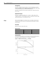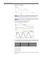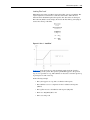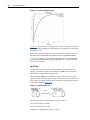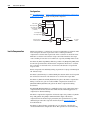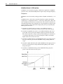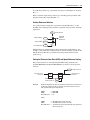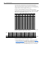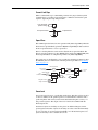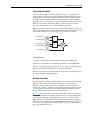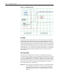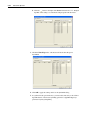
1
Adjustable
Frequency AC Drive
Phase II Control
Reference Manual
www.abpowerflex.com
Important User Information
Solid state equipment has operational characteristics differing from those of
electromechanical equipment. “Safety Guidelines for the Application,
Installation and Maintenance of Solid State Controls” (Publication SGI-1.1
available from your local Rockwell Automation Sales Office or online at
http://www.ab.com/manuals/gi) describes some important differences
between solid state equipment and hard-wired electromechanical devices.
Because of this difference, and also because of the wide variety of uses for
solid state equipment, all persons responsible for applying this equipment
must satisfy themselves that each intended application of this equipment is
acceptable.
In no event will the Rockwell Automation be responsible or liable for
indirect or consequential damages resulting from the use or application of
this equipment.
The examples and diagrams in this manual are included solely for
illustrative purposes. Because of the many variables and requirements
associated with any particular installation, the Rockwell Automation cannot
assume responsibility or liability for actual use based on the examples and
diagrams.
No patent liability is assumed by Rockwell Automation with respect to use
of information, circuits, equipment, or software described in this manual.
Reproduction of the contents of this manual, in whole or in part, without
written permission of the Rockwell Automation is prohibited.
Throughout this manual we use notes to make you aware of safety
considerations.
!
ATTENTION: Identifies information about practices or
circumstances that can lead to personal injury or death, property
damage, or economic loss.
Attentions help you:
• identify a hazard
• avoid the hazard
• recognize the consequences
Important: Identifies information that is especially important for successful
application and understanding of the product.
Shock Hazard labels may be located on or inside the drive to
alert people that dangerous voltage may be present.
DriveExplorer, DriveTools32, and SCANport are trademarks of Rockwell Automation.
PLC is a registered trademark of Rockwell Automation.
ControlNet is a trademark of ControlNet International, Ltd.
DeviceNet is a trademark of the Open DeviceNet Vendor Association.
COLOR-KEYED is a registered trademark of Thomas & Betts Corporation.
Summary of Changes
This information summarizes the changes to the PowerFlex® 700S
Adjustable Frequency AC Drive - Phase II Control Reference Manual,
publication PFLEX-RM003 since the last release.
Manual Updates
Change
Initial release of this publication
See Page...
soc-2
Notes:
Table of Contents
Important User Information . . . . . . . . . . . . . . . . . . . . . . . . . . . . . . . . . . . . . . . . . . . . . . . 1-2
Summary of
Changes
Manual Updates . . . . . . . . . . . . . . . . . . . . . . . . . . . . . . . . . . . . . . . . . . . . . . . . . . . . . . . . . i-1
Chapter 1
Specifications & Dimensions
PowerFlex 700S Specifications. . . . . . . . . . . . . . . . . . . . . . . . . . . . . . . . . . . . . . . . . . . . . 1-1
Input/Output Ratings . . . . . . . . . . . . . . . . . . . . . . . . . . . . . . . . . . . . . . . . . . . . . . . . . . . . . 1-4
Input Voltage Range/Tolerance . . . . . . . . . . . . . . . . . . . . . . . . . . . . . . . . . . . . . . . . . . . . . 1-5
Heat Dissipation . . . . . . . . . . . . . . . . . . . . . . . . . . . . . . . . . . . . . . . . . . . . . . . . . . . . . . . . 1-5
Mounting . . . . . . . . . . . . . . . . . . . . . . . . . . . . . . . . . . . . . . . . . . . . . . . . . . . . . . . . . . . . . . 1-6
Derating Guidelines . . . . . . . . . . . . . . . . . . . . . . . . . . . . . . . . . . . . . . . . . . . . . . . . . . . . . 1-8
PowerFlex 700S Altitude and Efficiency . . . . . . . . . . . . . . . . . . . . . . . . . . . . . . . . . . . 1-8
Dimensions . . . . . . . . . . . . . . . . . . . . . . . . . . . . . . . . . . . . . . . . . . . . . . . . . . . . . . . . . . . 1-11
Chapter 2
Detailed Drive Operation
Accel Time . . . . . . . . . . . . . . . . . . . . . . . . . . . . . . . . . . . . . . . . . . . . . . . . . . . . . . . . . . . . 2-1
Alarms . . . . . . . . . . . . . . . . . . . . . . . . . . . . . . . . . . . . . . . . . . . . . . . . . . . . . . . . . . . . . . . . 2-1
Configuration: . . . . . . . . . . . . . . . . . . . . . . . . . . . . . . . . . . . . . . . . . . . . . . . . . . . . . . . . 2-1
Application Example: . . . . . . . . . . . . . . . . . . . . . . . . . . . . . . . . . . . . . . . . . . . . . . . . . . 2-1
Analog Inputs . . . . . . . . . . . . . . . . . . . . . . . . . . . . . . . . . . . . . . . . . . . . . . . . . . . . . . . . . . 2-2
Analog Input Specifications . . . . . . . . . . . . . . . . . . . . . . . . . . . . . . . . . . . . . . . . . . . . . 2-2
Analog Input Configuration . . . . . . . . . . . . . . . . . . . . . . . . . . . . . . . . . . . . . . . . . . . . . 2-2
Configuration Example: . . . . . . . . . . . . . . . . . . . . . . . . . . . . . . . . . . . . . . . . . . . . . . . . 2-2
Analog Outputs . . . . . . . . . . . . . . . . . . . . . . . . . . . . . . . . . . . . . . . . . . . . . . . . . . . . . . . . . 2-3
Analog Output Specifications . . . . . . . . . . . . . . . . . . . . . . . . . . . . . . . . . . . . . . . . . . . . 2-3
Analog Output Configuration . . . . . . . . . . . . . . . . . . . . . . . . . . . . . . . . . . . . . . . . . . . . 2-3
Example Configuration 1: . . . . . . . . . . . . . . . . . . . . . . . . . . . . . . . . . . . . . . . . . . . . . . . 2-4
Example Configuration 2: . . . . . . . . . . . . . . . . . . . . . . . . . . . . . . . . . . . . . . . . . . . . . . . 2-4
Auto/Manual . . . . . . . . . . . . . . . . . . . . . . . . . . . . . . . . . . . . . . . . . . . . . . . . . . . . . . . . . . . 2-4
Autotune . . . . . . . . . . . . . . . . . . . . . . . . . . . . . . . . . . . . . . . . . . . . . . . . . . . . . . . . . . . . . . 2-4
Autotune - Start-Up Menu. . . . . . . . . . . . . . . . . . . . . . . . . . . . . . . . . . . . . . . . . . . . . . . 2-4
Motor Control . . . . . . . . . . . . . . . . . . . . . . . . . . . . . . . . . . . . . . . . . . . . . . . . . . . . . . . . 2-5
Motor Data . . . . . . . . . . . . . . . . . . . . . . . . . . . . . . . . . . . . . . . . . . . . . . . . . . . . . . . . . . 2-5
Feedback Configuration . . . . . . . . . . . . . . . . . . . . . . . . . . . . . . . . . . . . . . . . . . . . . . . . 2-5
Power Circuit Test . . . . . . . . . . . . . . . . . . . . . . . . . . . . . . . . . . . . . . . . . . . . . . . . . . . . . 2-5
Direction Test . . . . . . . . . . . . . . . . . . . . . . . . . . . . . . . . . . . . . . . . . . . . . . . . . . . . . . . . 2-5
Motor Tests . . . . . . . . . . . . . . . . . . . . . . . . . . . . . . . . . . . . . . . . . . . . . . . . . . . . . . . . . . 2-6
Inertia Test. . . . . . . . . . . . . . . . . . . . . . . . . . . . . . . . . . . . . . . . . . . . . . . . . . . . . . . . . . . 2-6
Troubleshooting a "MC Commissn Fail" Fault during Autotune . . . . . . . . . . . . . . . . . 2-7
Auxiliary Power Supply . . . . . . . . . . . . . . . . . . . . . . . . . . . . . . . . . . . . . . . . . . . . . . . . . . 2-7
Bus Regulation/Braking . . . . . . . . . . . . . . . . . . . . . . . . . . . . . . . . . . . . . . . . . . . . . . . . . . 2-7
Description . . . . . . . . . . . . . . . . . . . . . . . . . . . . . . . . . . . . . . . . . . . . . . . . . . . . . . . . . . 2-7
Technical Information . . . . . . . . . . . . . . . . . . . . . . . . . . . . . . . . . . . . . . . . . . . . . . . . . . 2-7
Bus Regulator/Braking Configuration. . . . . . . . . . . . . . . . . . . . . . . . . . . . . . . . . . . . . . 2-8
Cable, Control . . . . . . . . . . . . . . . . . . . . . . . . . . . . . . . . . . . . . . . . . . . . . . . . . . . . . . . . . 2-11
Cable, Motor Lengths . . . . . . . . . . . . . . . . . . . . . . . . . . . . . . . . . . . . . . . . . . . . . . . . . . . 2-11
Cable, Power . . . . . . . . . . . . . . . . . . . . . . . . . . . . . . . . . . . . . . . . . . . . . . . . . . . . . . . . . . 2-11
Cable Trays and Conduit. . . . . . . . . . . . . . . . . . . . . . . . . . . . . . . . . . . . . . . . . . . . . . . . . 2-12
Carrier (PWM) Frequency . . . . . . . . . . . . . . . . . . . . . . . . . . . . . . . . . . . . . . . . . . . . . . . 2-12
ii
Common Bus Systems . . . . . . . . . . . . . . . . . . . . . . . . . . . . . . . . . . . . . . . . . . . . . . . . . . .
Communications . . . . . . . . . . . . . . . . . . . . . . . . . . . . . . . . . . . . . . . . . . . . . . . . . . . . . . .
ControlLogix® System . . . . . . . . . . . . . . . . . . . . . . . . . . . . . . . . . . . . . . . . . . . . . . . .
PLC 5 or SLC System . . . . . . . . . . . . . . . . . . . . . . . . . . . . . . . . . . . . . . . . . . . . . . . . .
Copy Cat . . . . . . . . . . . . . . . . . . . . . . . . . . . . . . . . . . . . . . . . . . . . . . . . . . . . . . . . . . . . .
Current Limit . . . . . . . . . . . . . . . . . . . . . . . . . . . . . . . . . . . . . . . . . . . . . . . . . . . . . . . . . .
Datalinks . . . . . . . . . . . . . . . . . . . . . . . . . . . . . . . . . . . . . . . . . . . . . . . . . . . . . . . . . . . . .
Configuring Datalinks . . . . . . . . . . . . . . . . . . . . . . . . . . . . . . . . . . . . . . . . . . . . . . . . .
Decel Time. . . . . . . . . . . . . . . . . . . . . . . . . . . . . . . . . . . . . . . . . . . . . . . . . . . . . . . . . . . .
Digital Inputs . . . . . . . . . . . . . . . . . . . . . . . . . . . . . . . . . . . . . . . . . . . . . . . . . . . . . . . . . .
Technical Information . . . . . . . . . . . . . . . . . . . . . . . . . . . . . . . . . . . . . . . . . . . . . . . . .
Digital Input Configuration . . . . . . . . . . . . . . . . . . . . . . . . . . . . . . . . . . . . . . . . . . . . .
Digital Outputs. . . . . . . . . . . . . . . . . . . . . . . . . . . . . . . . . . . . . . . . . . . . . . . . . . . . . . . . .
Technical Information . . . . . . . . . . . . . . . . . . . . . . . . . . . . . . . . . . . . . . . . . . . . . . . . .
Digital Output Configuration. . . . . . . . . . . . . . . . . . . . . . . . . . . . . . . . . . . . . . . . . . . .
Digital Output Status Bits . . . . . . . . . . . . . . . . . . . . . . . . . . . . . . . . . . . . . . . . . . . . . .
Direction Control and Bipolar Reference . . . . . . . . . . . . . . . . . . . . . . . . . . . . . . . . . . . .
Drive Peripheral Interface (DPI) . . . . . . . . . . . . . . . . . . . . . . . . . . . . . . . . . . . . . . . . . . .
Client/Server . . . . . . . . . . . . . . . . . . . . . . . . . . . . . . . . . . . . . . . . . . . . . . . . . . . . . . . .
Producer/Consumer Operation Overview . . . . . . . . . . . . . . . . . . . . . . . . . . . . . . . . . .
Peer-to-Peer Operation. . . . . . . . . . . . . . . . . . . . . . . . . . . . . . . . . . . . . . . . . . . . . . . . .
DriveLogix. . . . . . . . . . . . . . . . . . . . . . . . . . . . . . . . . . . . . . . . . . . . . . . . . . . . . . . . . . . .
Drive Overload. . . . . . . . . . . . . . . . . . . . . . . . . . . . . . . . . . . . . . . . . . . . . . . . . . . . . . . . .
Theory of Operation. . . . . . . . . . . . . . . . . . . . . . . . . . . . . . . . . . . . . . . . . . . . . . . . . . .
Drive Over Temperature
(Frame 9 Only) . . . . . . . . . . . . . . . . . . . . . . . . . . . . . . . . . . . . . . . . . . . . . . . . . . . . . . . .
Droop . . . . . . . . . . . . . . . . . . . . . . . . . . . . . . . . . . . . . . . . . . . . . . . . . . . . . . . . . . . . . . . .
Dynamic Braking. . . . . . . . . . . . . . . . . . . . . . . . . . . . . . . . . . . . . . . . . . . . . . . . . . . . . . .
Efficiency . . . . . . . . . . . . . . . . . . . . . . . . . . . . . . . . . . . . . . . . . . . . . . . . . . . . . . . . . . . . .
Electronic Gearing . . . . . . . . . . . . . . . . . . . . . . . . . . . . . . . . . . . . . . . . . . . . . . . . . . . . . .
CE Conformity. . . . . . . . . . . . . . . . . . . . . . . . . . . . . . . . . . . . . . . . . . . . . . . . . . . . . . . . .
Low Voltage Directive (73/23/EEC) . . . . . . . . . . . . . . . . . . . . . . . . . . . . . . . . . . . . . .
EMC Directive (89/336/EEC) . . . . . . . . . . . . . . . . . . . . . . . . . . . . . . . . . . . . . . . . . . .
General Notes . . . . . . . . . . . . . . . . . . . . . . . . . . . . . . . . . . . . . . . . . . . . . . . . . . . . . . .
Essential Requirements for CE Compliance . . . . . . . . . . . . . . . . . . . . . . . . . . . . . . . .
Faults . . . . . . . . . . . . . . . . . . . . . . . . . . . . . . . . . . . . . . . . . . . . . . . . . . . . . . . . . . . . . . . .
Configuration: . . . . . . . . . . . . . . . . . . . . . . . . . . . . . . . . . . . . . . . . . . . . . . . . . . . . . . .
Application Example . . . . . . . . . . . . . . . . . . . . . . . . . . . . . . . . . . . . . . . . . . . . . . . . . .
Filters . . . . . . . . . . . . . . . . . . . . . . . . . . . . . . . . . . . . . . . . . . . . . . . . . . . . . . . . . . . . . . . .
Key Words . . . . . . . . . . . . . . . . . . . . . . . . . . . . . . . . . . . . . . . . . . . . . . . . . . . . . . . . . .
Nomenclature: . . . . . . . . . . . . . . . . . . . . . . . . . . . . . . . . . . . . . . . . . . . . . . . . . . . . . . .
Low Pass Filter . . . . . . . . . . . . . . . . . . . . . . . . . . . . . . . . . . . . . . . . . . . . . . . . . . . . . .
Second Order Low Pass Filter . . . . . . . . . . . . . . . . . . . . . . . . . . . . . . . . . . . . . . . . . . .
Lead-Lag Filter . . . . . . . . . . . . . . . . . . . . . . . . . . . . . . . . . . . . . . . . . . . . . . . . . . . . . .
Notch Filter . . . . . . . . . . . . . . . . . . . . . . . . . . . . . . . . . . . . . . . . . . . . . . . . . . . . . . . . .
Conclusion . . . . . . . . . . . . . . . . . . . . . . . . . . . . . . . . . . . . . . . . . . . . . . . . . . . . . . . . . .
Firmware Functions . . . . . . . . . . . . . . . . . . . . . . . . . . . . . . . . . . . . . . . . . . . . . . . . . . . . .
Flying Start . . . . . . . . . . . . . . . . . . . . . . . . . . . . . . . . . . . . . . . . . . . . . . . . . . . . . . . . . . .
Configuration . . . . . . . . . . . . . . . . . . . . . . . . . . . . . . . . . . . . . . . . . . . . . . . . . . . . . . . .
Friction Compensation. . . . . . . . . . . . . . . . . . . . . . . . . . . . . . . . . . . . . . . . . . . . . . . . . . .
Fuses and Circuit Breakers . . . . . . . . . . . . . . . . . . . . . . . . . . . . . . . . . . . . . . . . . . . . . . .
2-13
2-13
2-13
2-15
2-19
2-20
2-20
2-20
2-21
2-22
2-22
2-22
2-23
2-23
2-23
2-24
2-24
2-25
2-25
2-26
2-26
2-27
2-27
2-27
2-29
2-29
2-29
2-30
2-30
2-30
2-30
2-30
2-31
2-31
2-31
2-32
2-32
2-32
2-32
2-32
2-32
2-33
2-33
2-36
2-38
2-39
2-39
2-39
2-40
2-41
iii
Fusing . . . . . . . . . . . . . . . . . . . . . . . . . . . . . . . . . . . . . . . . . . . . . . . . . . . . . . . . . . . . .
Circuit Breakers. . . . . . . . . . . . . . . . . . . . . . . . . . . . . . . . . . . . . . . . . . . . . . . . . . . . . .
Grounding, General. . . . . . . . . . . . . . . . . . . . . . . . . . . . . . . . . . . . . . . . . . . . . . . . . . . . .
HIM Memory . . . . . . . . . . . . . . . . . . . . . . . . . . . . . . . . . . . . . . . . . . . . . . . . . . . . . . . . .
HIM Operations . . . . . . . . . . . . . . . . . . . . . . . . . . . . . . . . . . . . . . . . . . . . . . . . . . . . . . .
The User Display. . . . . . . . . . . . . . . . . . . . . . . . . . . . . . . . . . . . . . . . . . . . . . . . . . . . .
Indexer. . . . . . . . . . . . . . . . . . . . . . . . . . . . . . . . . . . . . . . . . . . . . . . . . . . . . . . . . . . . . . .
Configuring the Indexer . . . . . . . . . . . . . . . . . . . . . . . . . . . . . . . . . . . . . . . . . . . . . . .
Inertia Adaptation . . . . . . . . . . . . . . . . . . . . . . . . . . . . . . . . . . . . . . . . . . . . . . . . . . . . . .
Configuration: . . . . . . . . . . . . . . . . . . . . . . . . . . . . . . . . . . . . . . . . . . . . . . . . . . . . . . .
Inertia Compensation . . . . . . . . . . . . . . . . . . . . . . . . . . . . . . . . . . . . . . . . . . . . . . . . . . .
Input Devices. . . . . . . . . . . . . . . . . . . . . . . . . . . . . . . . . . . . . . . . . . . . . . . . . . . . . . . . . .
Contactors . . . . . . . . . . . . . . . . . . . . . . . . . . . . . . . . . . . . . . . . . . . . . . . . . . . . . . . . . .
Circuit Breakers/Fuses . . . . . . . . . . . . . . . . . . . . . . . . . . . . . . . . . . . . . . . . . . . . . . . .
Filters, EMC . . . . . . . . . . . . . . . . . . . . . . . . . . . . . . . . . . . . . . . . . . . . . . . . . . . . . . . .
Input Modes . . . . . . . . . . . . . . . . . . . . . . . . . . . . . . . . . . . . . . . . . . . . . . . . . . . . . . . . . .
Input Power Conditioning . . . . . . . . . . . . . . . . . . . . . . . . . . . . . . . . . . . . . . . . . . . . . . . .
Jog . . . . . . . . . . . . . . . . . . . . . . . . . . . . . . . . . . . . . . . . . . . . . . . . . . . . . . . . . . . . . . . . . .
Limit Generator . . . . . . . . . . . . . . . . . . . . . . . . . . . . . . . . . . . . . . . . . . . . . . . . . . . . . . . .
Links . . . . . . . . . . . . . . . . . . . . . . . . . . . . . . . . . . . . . . . . . . . . . . . . . . . . . . . . . . . . . . . .
Using the HIM. . . . . . . . . . . . . . . . . . . . . . . . . . . . . . . . . . . . . . . . . . . . . . . . . . . . . . .
Using Drive Executive. . . . . . . . . . . . . . . . . . . . . . . . . . . . . . . . . . . . . . . . . . . . . . . . .
Masks . . . . . . . . . . . . . . . . . . . . . . . . . . . . . . . . . . . . . . . . . . . . . . . . . . . . . . . . . . . . . . .
Motor Control Mode . . . . . . . . . . . . . . . . . . . . . . . . . . . . . . . . . . . . . . . . . . . . . . . . . . . .
Field Oriented Control . . . . . . . . . . . . . . . . . . . . . . . . . . . . . . . . . . . . . . . . . . . . . . . .
Permanent Magnet Control . . . . . . . . . . . . . . . . . . . . . . . . . . . . . . . . . . . . . . . . . . . . .
Volts/Hertz Control - v2.003 and later . . . . . . . . . . . . . . . . . . . . . . . . . . . . . . . . . . . .
Motor Nameplate . . . . . . . . . . . . . . . . . . . . . . . . . . . . . . . . . . . . . . . . . . . . . . . . . . . . . .
Motor Overload . . . . . . . . . . . . . . . . . . . . . . . . . . . . . . . . . . . . . . . . . . . . . . . . . . . . . . . .
Low Overload . . . . . . . . . . . . . . . . . . . . . . . . . . . . . . . . . . . . . . . . . . . . . . . . . . . . . . .
High Overload . . . . . . . . . . . . . . . . . . . . . . . . . . . . . . . . . . . . . . . . . . . . . . . . . . . . . . .
Motor Start/Stop Precautions . . . . . . . . . . . . . . . . . . . . . . . . . . . . . . . . . . . . . . . . . . . . .
Input Contactor Precautions . . . . . . . . . . . . . . . . . . . . . . . . . . . . . . . . . . . . . . . . . . . .
Output Contactor Precaution. . . . . . . . . . . . . . . . . . . . . . . . . . . . . . . . . . . . . . . . . . . .
Mounting . . . . . . . . . . . . . . . . . . . . . . . . . . . . . . . . . . . . . . . . . . . . . . . . . . . . . . . . . . . . .
Output Devices . . . . . . . . . . . . . . . . . . . . . . . . . . . . . . . . . . . . . . . . . . . . . . . . . . . . . . . .
Drive Output Disconnection . . . . . . . . . . . . . . . . . . . . . . . . . . . . . . . . . . . . . . . . . . . .
Cable Termination . . . . . . . . . . . . . . . . . . . . . . . . . . . . . . . . . . . . . . . . . . . . . . . . . . . .
Output Reactor . . . . . . . . . . . . . . . . . . . . . . . . . . . . . . . . . . . . . . . . . . . . . . . . . . . . . .
Output Display . . . . . . . . . . . . . . . . . . . . . . . . . . . . . . . . . . . . . . . . . . . . . . . . . . . . . . . .
Output Current (Parameter 308) . . . . . . . . . . . . . . . . . . . . . . . . . . . . . . . . . . . . . . . . .
Output Frequency (Parameter 310) . . . . . . . . . . . . . . . . . . . . . . . . . . . . . . . . . . . . . . .
Output Power (Parameter 311) . . . . . . . . . . . . . . . . . . . . . . . . . . . . . . . . . . . . . . . . . .
Output Voltage (Parameter 307) . . . . . . . . . . . . . . . . . . . . . . . . . . . . . . . . . . . . . . . . .
Overspeed Limit . . . . . . . . . . . . . . . . . . . . . . . . . . . . . . . . . . . . . . . . . . . . . . . . . . . . . . .
Owners . . . . . . . . . . . . . . . . . . . . . . . . . . . . . . . . . . . . . . . . . . . . . . . . . . . . . . . . . . . . . .
Peak Detect . . . . . . . . . . . . . . . . . . . . . . . . . . . . . . . . . . . . . . . . . . . . . . . . . . . . . . . . . . .
Permanent Magnet Motors . . . . . . . . . . . . . . . . . . . . . . . . . . . . . . . . . . . . . . . . . . . . . . .
PET . . . . . . . . . . . . . . . . . . . . . . . . . . . . . . . . . . . . . . . . . . . . . . . . . . . . . . . . . . . . . . . . .
Position Loop - Follower (Electronic Gearing). . . . . . . . . . . . . . . . . . . . . . . . . . . . . . . .
Technical Information . . . . . . . . . . . . . . . . . . . . . . . . . . . . . . . . . . . . . . . . . . . . . . . . .
2-41
2-41
2-51
2-51
2-51
2-51
2-52
2-52
2-53
2-54
2-54
2-55
2-55
2-55
2-55
2-55
2-55
2-55
2-56
2-56
2-57
2-57
2-58
2-58
2-59
2-59
2-60
2-61
2-61
2-61
2-62
2-62
2-62
2-62
2-62
2-63
2-63
2-63
2-63
2-63
2-63
2-63
2-63
2-64
2-64
2-64
2-66
2-67
2-69
2-69
2-69
iv
Overview . . . . . . . . . . . . . . . . . . . . . . . . . . . . . . . . . . . . . . . . . . . . . . . . . . . . . . . . . . .
Speed Reference Selection. . . . . . . . . . . . . . . . . . . . . . . . . . . . . . . . . . . . . . . . . . . . . .
Speed Reference Ramp . . . . . . . . . . . . . . . . . . . . . . . . . . . . . . . . . . . . . . . . . . . . . . . .
Enabling the Position Loop . . . . . . . . . . . . . . . . . . . . . . . . . . . . . . . . . . . . . . . . . . . . .
Position Reference Selection . . . . . . . . . . . . . . . . . . . . . . . . . . . . . . . . . . . . . . . . . . . .
Setting the Electronic Gear Ratio (EGR) and Speed Reference Scaling. . . . . . . . . . .
Position Offset . . . . . . . . . . . . . . . . . . . . . . . . . . . . . . . . . . . . . . . . . . . . . . . . . . . . . . .
Position Loop Output Limits . . . . . . . . . . . . . . . . . . . . . . . . . . . . . . . . . . . . . . . . . . . .
Tuning Tips . . . . . . . . . . . . . . . . . . . . . . . . . . . . . . . . . . . . . . . . . . . . . . . . . . . . . . . . .
Jogging a Position Follower Independent from the Master . . . . . . . . . . . . . . . . . . . . .
Position Loop - In Position Detect. . . . . . . . . . . . . . . . . . . . . . . . . . . . . . . . . . . . . . . . . .
Position Loop - Point to Point . . . . . . . . . . . . . . . . . . . . . . . . . . . . . . . . . . . . . . . . . . . . .
Technical Information . . . . . . . . . . . . . . . . . . . . . . . . . . . . . . . . . . . . . . . . . . . . . . . . .
Overview . . . . . . . . . . . . . . . . . . . . . . . . . . . . . . . . . . . . . . . . . . . . . . . . . . . . . . . . . . .
Speed Reference Selection. . . . . . . . . . . . . . . . . . . . . . . . . . . . . . . . . . . . . . . . . . . . . .
Enabling the Position Loop . . . . . . . . . . . . . . . . . . . . . . . . . . . . . . . . . . . . . . . . . . . . .
Position Reference Selection . . . . . . . . . . . . . . . . . . . . . . . . . . . . . . . . . . . . . . . . . . . .
Position Reference Scaling . . . . . . . . . . . . . . . . . . . . . . . . . . . . . . . . . . . . . . . . . . . . .
Position Offset . . . . . . . . . . . . . . . . . . . . . . . . . . . . . . . . . . . . . . . . . . . . . . . . . . . . . . .
Point to Point Acceleration and Deceleration . . . . . . . . . . . . . . . . . . . . . . . . . . . . . . .
Position Loop Output Limits . . . . . . . . . . . . . . . . . . . . . . . . . . . . . . . . . . . . . . . . . . . .
Tuning Tips . . . . . . . . . . . . . . . . . . . . . . . . . . . . . . . . . . . . . . . . . . . . . . . . . . . . . . . . .
Jogging. . . . . . . . . . . . . . . . . . . . . . . . . . . . . . . . . . . . . . . . . . . . . . . . . . . . . . . . . . . . .
Point to Point Re-Reference . . . . . . . . . . . . . . . . . . . . . . . . . . . . . . . . . . . . . . . . . . . .
Absolute Point to Point Positioning: . . . . . . . . . . . . . . . . . . . . . . . . . . . . . . . . . . . . . .
Example to Control the Point to Point Position with Digital Inputs:. . . . . . . . . . . . . .
Position Loop - Position Watch . . . . . . . . . . . . . . . . . . . . . . . . . . . . . . . . . . . . . . . . . . . .
Position Loop - Registration . . . . . . . . . . . . . . . . . . . . . . . . . . . . . . . . . . . . . . . . . . . . . .
Encoder 0 and 1 Registration. . . . . . . . . . . . . . . . . . . . . . . . . . . . . . . . . . . . . . . . . . . .
Feedback Option 0 and 1 Registration. . . . . . . . . . . . . . . . . . . . . . . . . . . . . . . . . . . . .
Power Loss/Ride Through . . . . . . . . . . . . . . . . . . . . . . . . . . . . . . . . . . . . . . . . . . . . . . . .
Precharge Frames 1 through 4 . . . . . . . . . . . . . . . . . . . . . . . . . . . . . . . . . . . . . . . . . . .
Precharge Frames 5 and Higher AC Input "Stand Alone Drives" . . . . . . . . . . . . . . . .
Precharge Frames 5 and Higher DC Input "Common Bus Drives" . . . . . . . . . . . . . . .
Ride Through Operation . . . . . . . . . . . . . . . . . . . . . . . . . . . . . . . . . . . . . . . . . . . . . . .
Ride Through Configuration . . . . . . . . . . . . . . . . . . . . . . . . . . . . . . . . . . . . . . . . . . . .
Ride Through Timeout Fault . . . . . . . . . . . . . . . . . . . . . . . . . . . . . . . . . . . . . . . . . . . .
Precharge Operation . . . . . . . . . . . . . . . . . . . . . . . . . . . . . . . . . . . . . . . . . . . . . . . . . .
Precharge Timeout Fault . . . . . . . . . . . . . . . . . . . . . . . . . . . . . . . . . . . . . . . . . . . . . . .
External Precharge . . . . . . . . . . . . . . . . . . . . . . . . . . . . . . . . . . . . . . . . . . . . . . . . . . . .
Precharge Staging . . . . . . . . . . . . . . . . . . . . . . . . . . . . . . . . . . . . . . . . . . . . . . . . . . . .
Motor Sim Mode . . . . . . . . . . . . . . . . . . . . . . . . . . . . . . . . . . . . . . . . . . . . . . . . . . . . .
External Power Supply . . . . . . . . . . . . . . . . . . . . . . . . . . . . . . . . . . . . . . . . . . . . . . . .
Preset Speeds . . . . . . . . . . . . . . . . . . . . . . . . . . . . . . . . . . . . . . . . . . . . . . . . . . . . . . . . . .
Process PI Loop . . . . . . . . . . . . . . . . . . . . . . . . . . . . . . . . . . . . . . . . . . . . . . . . . . . . . . . .
Process PI Reference and Feedback . . . . . . . . . . . . . . . . . . . . . . . . . . . . . . . . . . . . . .
Process PI Regulator . . . . . . . . . . . . . . . . . . . . . . . . . . . . . . . . . . . . . . . . . . . . . . . . . .
Process PI Limits . . . . . . . . . . . . . . . . . . . . . . . . . . . . . . . . . . . . . . . . . . . . . . . . . . . . .
Process PI Output. . . . . . . . . . . . . . . . . . . . . . . . . . . . . . . . . . . . . . . . . . . . . . . . . . . . .
Reflected Wave . . . . . . . . . . . . . . . . . . . . . . . . . . . . . . . . . . . . . . . . . . . . . . . . . . . . . . . .
RFI Filter Grounding . . . . . . . . . . . . . . . . . . . . . . . . . . . . . . . . . . . . . . . . . . . . . . . . . . . .
2-69
2-70
2-70
2-70
2-71
2-71
2-72
2-73
2-73
2-73
2-74
2-74
2-74
2-74
2-75
2-75
2-75
2-76
2-76
2-77
2-77
2-77
2-78
2-78
2-78
2-78
2-80
2-81
2-81
2-84
2-86
2-86
2-87
2-87
2-87
2-88
2-88
2-88
2-90
2-91
2-91
2-91
2-92
2-92
2-92
2-92
2-93
2-93
2-93
2-94
2-95
v
S-Curve . . . . . . . . . . . . . . . . . . . . . . . . . . . . . . . . . . . . . . . . . . . . . . . . . . . . . . . . . . . . . . 2-95
Skip Speeds . . . . . . . . . . . . . . . . . . . . . . . . . . . . . . . . . . . . . . . . . . . . . . . . . . . . . . . . . . . 2-96
Configuration: . . . . . . . . . . . . . . . . . . . . . . . . . . . . . . . . . . . . . . . . . . . . . . . . . . . . . . . 2-96
Slip Compensation . . . . . . . . . . . . . . . . . . . . . . . . . . . . . . . . . . . . . . . . . . . . . . . . . . . . . 2-97
Configuration: . . . . . . . . . . . . . . . . . . . . . . . . . . . . . . . . . . . . . . . . . . . . . . . . . . . . . . . 2-98
Speed Control, Speed Mode, Speed Regulation . . . . . . . . . . . . . . . . . . . . . . . . . . . . . . . 2-99
Speed/Position Feedback . . . . . . . . . . . . . . . . . . . . . . . . . . . . . . . . . . . . . . . . . . . . . . . . 2-99
Feedback Device . . . . . . . . . . . . . . . . . . . . . . . . . . . . . . . . . . . . . . . . . . . . . . . . . . . . . 2-99
Encoder . . . . . . . . . . . . . . . . . . . . . . . . . . . . . . . . . . . . . . . . . . . . . . . . . . . . . . . . . . . . 2-99
FIR Filter . . . . . . . . . . . . . . . . . . . . . . . . . . . . . . . . . . . . . . . . . . . . . . . . . . . . . . . . . . 2-102
Sensorless . . . . . . . . . . . . . . . . . . . . . . . . . . . . . . . . . . . . . . . . . . . . . . . . . . . . . . . . . 2-103
Motor Simulator . . . . . . . . . . . . . . . . . . . . . . . . . . . . . . . . . . . . . . . . . . . . . . . . . . . . 2-103
Feedback Option Cards . . . . . . . . . . . . . . . . . . . . . . . . . . . . . . . . . . . . . . . . . . . . . . . 2-104
Motor Speed Feedback and Scaled Speed Feedback . . . . . . . . . . . . . . . . . . . . . . . . 2-109
Position Feedback . . . . . . . . . . . . . . . . . . . . . . . . . . . . . . . . . . . . . . . . . . . . . . . . . . . 2-110
Speed Feedback Loss Ride Through. . . . . . . . . . . . . . . . . . . . . . . . . . . . . . . . . . . . . 2-110
Speed Reference . . . . . . . . . . . . . . . . . . . . . . . . . . . . . . . . . . . . . . . . . . . . . . . . . . . . . . 2-113
Speed Reference Select . . . . . . . . . . . . . . . . . . . . . . . . . . . . . . . . . . . . . . . . . . . . . . . 2-113
Speed Reference Scaling. . . . . . . . . . . . . . . . . . . . . . . . . . . . . . . . . . . . . . . . . . . . . . 2-114
Jog Reference . . . . . . . . . . . . . . . . . . . . . . . . . . . . . . . . . . . . . . . . . . . . . . . . . . . . . . 2-115
Direction Control and Bipolar Reference . . . . . . . . . . . . . . . . . . . . . . . . . . . . . . . . . 2-115
Speed Reference Limits . . . . . . . . . . . . . . . . . . . . . . . . . . . . . . . . . . . . . . . . . . . . . . 2-115
Stop Command . . . . . . . . . . . . . . . . . . . . . . . . . . . . . . . . . . . . . . . . . . . . . . . . . . . . . 2-115
Accel/Decel Ramp and S-Curve . . . . . . . . . . . . . . . . . . . . . . . . . . . . . . . . . . . . . . . . 2-115
Speed Reference Bypass and Delayed Speed Reference . . . . . . . . . . . . . . . . . . . . . 2-117
Inertia Compensation . . . . . . . . . . . . . . . . . . . . . . . . . . . . . . . . . . . . . . . . . . . . . . . . 2-117
Friction Compensation . . . . . . . . . . . . . . . . . . . . . . . . . . . . . . . . . . . . . . . . . . . . . . . 2-117
Virtual Encoder . . . . . . . . . . . . . . . . . . . . . . . . . . . . . . . . . . . . . . . . . . . . . . . . . . . . . 2-117
Speed Reference Filter . . . . . . . . . . . . . . . . . . . . . . . . . . . . . . . . . . . . . . . . . . . . . . . 2-118
Speed Reference Scale . . . . . . . . . . . . . . . . . . . . . . . . . . . . . . . . . . . . . . . . . . . . . . . 2-118
Speed Trim 1 . . . . . . . . . . . . . . . . . . . . . . . . . . . . . . . . . . . . . . . . . . . . . . . . . . . . . . . 2-118
Speed PI Regulator . . . . . . . . . . . . . . . . . . . . . . . . . . . . . . . . . . . . . . . . . . . . . . . . . . . . 2-119
Speed Trim . . . . . . . . . . . . . . . . . . . . . . . . . . . . . . . . . . . . . . . . . . . . . . . . . . . . . . . . 2-119
Autotune Speed Reference . . . . . . . . . . . . . . . . . . . . . . . . . . . . . . . . . . . . . . . . . . . . 2-120
Speed Reference Limits . . . . . . . . . . . . . . . . . . . . . . . . . . . . . . . . . . . . . . . . . . . . . . 2-120
Current Limit Stop . . . . . . . . . . . . . . . . . . . . . . . . . . . . . . . . . . . . . . . . . . . . . . . . . . 2-121
Speed Error . . . . . . . . . . . . . . . . . . . . . . . . . . . . . . . . . . . . . . . . . . . . . . . . . . . . . . . . 2-121
Servo Lock . . . . . . . . . . . . . . . . . . . . . . . . . . . . . . . . . . . . . . . . . . . . . . . . . . . . . . . . 2-121
Speed Regulator Gains . . . . . . . . . . . . . . . . . . . . . . . . . . . . . . . . . . . . . . . . . . . . . . . 2-122
Speed Regulation Anti-Backup . . . . . . . . . . . . . . . . . . . . . . . . . . . . . . . . . . . . . . . . . 2-122
Proportional Gain . . . . . . . . . . . . . . . . . . . . . . . . . . . . . . . . . . . . . . . . . . . . . . . . . . . 2-123
Integral Gain . . . . . . . . . . . . . . . . . . . . . . . . . . . . . . . . . . . . . . . . . . . . . . . . . . . . . . . 2-123
Droop. . . . . . . . . . . . . . . . . . . . . . . . . . . . . . . . . . . . . . . . . . . . . . . . . . . . . . . . . . . . . 2-124
Speed Regulator Output Limits. . . . . . . . . . . . . . . . . . . . . . . . . . . . . . . . . . . . . . . . . 2-124
Speed Regulator Output Filter. . . . . . . . . . . . . . . . . . . . . . . . . . . . . . . . . . . . . . . . . . 2-124
Speed Regulator Tuning . . . . . . . . . . . . . . . . . . . . . . . . . . . . . . . . . . . . . . . . . . . . . . . . 2-125
Basic Tuning with a Gear Box or Belt . . . . . . . . . . . . . . . . . . . . . . . . . . . . . . . . . . . 2-125
Advanced Tuning for the Speed Regulator with Gearbox or Belt . . . . . . . . . . . . . . 2-126
Speed/Torque Mode Select . . . . . . . . . . . . . . . . . . . . . . . . . . . . . . . . . . . . . . . . . . . . . . 2-127
Speed Regulation Mode . . . . . . . . . . . . . . . . . . . . . . . . . . . . . . . . . . . . . . . . . . . . . . 2-128
Torque Regulation Mode. . . . . . . . . . . . . . . . . . . . . . . . . . . . . . . . . . . . . . . . . . . . . . 2-129
vi
Min Mode / Max Mode . . . . . . . . . . . . . . . . . . . . . . . . . . . . . . . . . . . . . . . . . . . . . . .
Sum Mode . . . . . . . . . . . . . . . . . . . . . . . . . . . . . . . . . . . . . . . . . . . . . . . . . . . . . . . . .
Zero Torque Mode . . . . . . . . . . . . . . . . . . . . . . . . . . . . . . . . . . . . . . . . . . . . . . . . . . .
Start Inhibits. . . . . . . . . . . . . . . . . . . . . . . . . . . . . . . . . . . . . . . . . . . . . . . . . . . . . . . . . .
Start/Stop Modes . . . . . . . . . . . . . . . . . . . . . . . . . . . . . . . . . . . . . . . . . . . . . . . . . . . . . .
Technical Information . . . . . . . . . . . . . . . . . . . . . . . . . . . . . . . . . . . . . . . . . . . . . . . .
Configuring the Start and Stop for 3-Wire Control (Momentary Start and Stop) . . .
Configuring the Start and Stop for 2-Wire Control (Maintained Start and Stop) . . .
Start-Up . . . . . . . . . . . . . . . . . . . . . . . . . . . . . . . . . . . . . . . . . . . . . . . . . . . . . . . . . . . . .
Stop Modes . . . . . . . . . . . . . . . . . . . . . . . . . . . . . . . . . . . . . . . . . . . . . . . . . . . . . . . . . .
SynchLink™ . . . . . . . . . . . . . . . . . . . . . . . . . . . . . . . . . . . . . . . . . . . . . . . . . . . . . . . . .
SynchLink Configuration . . . . . . . . . . . . . . . . . . . . . . . . . . . . . . . . . . . . . . . . . . . . .
SynchLink™ Direct Data . . . . . . . . . . . . . . . . . . . . . . . . . . . . . . . . . . . . . . . . . . . . .
Multiply Block. . . . . . . . . . . . . . . . . . . . . . . . . . . . . . . . . . . . . . . . . . . . . . . . . . . . . .
Buffered Data. . . . . . . . . . . . . . . . . . . . . . . . . . . . . . . . . . . . . . . . . . . . . . . . . . . . . . .
SynchLink Diagnostics:. . . . . . . . . . . . . . . . . . . . . . . . . . . . . . . . . . . . . . . . . . . . . . .
Speed Synchronization Example: . . . . . . . . . . . . . . . . . . . . . . . . . . . . . . . . . . . . . . .
Master PowerFlex® 700S Drive Setup (Transmitting Drive) . . . . . . . . . . . . . . . . . .
Follower PowerFlex® 700S Setup (Receiving Drive). . . . . . . . . . . . . . . . . . . . . . . .
Reset SynchLink™ . . . . . . . . . . . . . . . . . . . . . . . . . . . . . . . . . . . . . . . . . . . . . . . . . .
Sync Generator . . . . . . . . . . . . . . . . . . . . . . . . . . . . . . . . . . . . . . . . . . . . . . . . . . . . . . .
Configuration: . . . . . . . . . . . . . . . . . . . . . . . . . . . . . . . . . . . . . . . . . . . . . . . . . . . . . .
Task Time. . . . . . . . . . . . . . . . . . . . . . . . . . . . . . . . . . . . . . . . . . . . . . . . . . . . . . . . . . . .
Test Points . . . . . . . . . . . . . . . . . . . . . . . . . . . . . . . . . . . . . . . . . . . . . . . . . . . . . . . . . . .
Thermal Regulator . . . . . . . . . . . . . . . . . . . . . . . . . . . . . . . . . . . . . . . . . . . . . . . . . . . . .
Time Function Generator. . . . . . . . . . . . . . . . . . . . . . . . . . . . . . . . . . . . . . . . . . . . . . . .
Torque Reference. . . . . . . . . . . . . . . . . . . . . . . . . . . . . . . . . . . . . . . . . . . . . . . . . . . . . .
Torque Reference Input . . . . . . . . . . . . . . . . . . . . . . . . . . . . . . . . . . . . . . . . . . . . . . .
Trending. . . . . . . . . . . . . . . . . . . . . . . . . . . . . . . . . . . . . . . . . . . . . . . . . . . . . . . . . . . . .
Configuration: . . . . . . . . . . . . . . . . . . . . . . . . . . . . . . . . . . . . . . . . . . . . . . . . . . . . . .
Unbalanced or Ungrounded Distribution Systems . . . . . . . . . . . . . . . . . . . . . . . . . . . .
Unbalanced Distribution Systems . . . . . . . . . . . . . . . . . . . . . . . . . . . . . . . . . . . . . . .
Ungrounded Distribution Systems. . . . . . . . . . . . . . . . . . . . . . . . . . . . . . . . . . . . . . .
User Functions . . . . . . . . . . . . . . . . . . . . . . . . . . . . . . . . . . . . . . . . . . . . . . . . . . . . . . . .
Bit Swap. . . . . . . . . . . . . . . . . . . . . . . . . . . . . . . . . . . . . . . . . . . . . . . . . . . . . . . . . . .
MOP. . . . . . . . . . . . . . . . . . . . . . . . . . . . . . . . . . . . . . . . . . . . . . . . . . . . . . . . . . . . . .
Configuration: . . . . . . . . . . . . . . . . . . . . . . . . . . . . . . . . . . . . . . . . . . . . . . . . . . . . . .
Controlling the MOP from Digital Inputs: . . . . . . . . . . . . . . . . . . . . . . . . . . . . . . . .
Controlling the MOP from a Network or DriveLogix™ . . . . . . . . . . . . . . . . . . . . . .
Selector Switches. . . . . . . . . . . . . . . . . . . . . . . . . . . . . . . . . . . . . . . . . . . . . . . . . . . .
DInt to Real and Real to DInt Converters . . . . . . . . . . . . . . . . . . . . . . . . . . . . . . . . .
Logic Blocks . . . . . . . . . . . . . . . . . . . . . . . . . . . . . . . . . . . . . . . . . . . . . . . . . . . . . . .
Compare Blocks. . . . . . . . . . . . . . . . . . . . . . . . . . . . . . . . . . . . . . . . . . . . . . . . . . . . .
Multiply/Divide Blocks . . . . . . . . . . . . . . . . . . . . . . . . . . . . . . . . . . . . . . . . . . . . . . .
Voltage Class . . . . . . . . . . . . . . . . . . . . . . . . . . . . . . . . . . . . . . . . . . . . . . . . . . . . . . . . .
Watts Loss . . . . . . . . . . . . . . . . . . . . . . . . . . . . . . . . . . . . . . . . . . . . . . . . . . . . . . . . . . .
Index
2-129
2-130
2-130
2-131
2-131
2-131
2-132
2-133
2-134
2-134
2-134
2-134
2-135
2-137
2-138
2-139
2-140
2-141
2-143
2-143
2-144
2-144
2-145
2-145
2-145
2-145
2-146
2-146
2-146
2-146
2-148
2-148
2-148
2-149
2-149
2-150
2-151
2-151
2-152
2-152
2-155
2-156
2-158
2-159
2-159
2-160
Chapter
1
Specifications & Dimensions
PowerFlex 700S
Specifications
Category
Specification
Protection
AC Input Overvoltage Trip:
Bus Overvoltage Trip:
Bus Undervoltage Trip:
Nominal Bus Voltage:
Heat Sink Thermistor:
Drive Overcurrent Trip
Software Current Limit:
Hardware Current Limit:
Instantaneous Current Limit:
Line Transients:
Control Logic Noise Immunity:
Power Ride-Thru:
Logic Control Ride-Thru
Ground Fault Trip:
Short Circuit Trip:
Agency
Certification
UL
C
W
..
E
C
Production inspected
EN 50178
Bauart geprüft
Functional
..
TUV
Rheinland
Frames 9 & up
380/400V 480V
500V Drive 600V
Drive
Drive
Drive
475VAC
570V AC 611V AC 690VAC
675VDC 810VDC 810VDC 1013VDC
Adjustable
931VDC 540VDC 648VDC 645VDC 810VDC
Monitored by microprocessor overtemp trip
690V
Drive
863VAC
1164VDC
690V
Drive
863VAC
1164VDC
931VDC
Calculated value, 105% of motor rated to 200% of drive rated
105% of 3 sec. rating (158%-210%)
143% of 3 sec rating (215%-287%)
Up to 6000 volts peak per IEEE C62.41-1991
Showering arc transients up to 1500V peak
15 milliseconds at full load
0.25 sec., drive not running
Phase-to-ground on drive output
Phase-to-phase on drive output
The drive is designed to meet applicable requirements of the
following codes/standards:
IEC 61800-2 Adjustable speed electrical power drive systems General requirements
IEC 61800-5-1 Adjustable speed electrical power drive systems
- Safety requirements
NFPA 70 – US National Electric Code
NEMA 250 – Enclosures for Electrical Equipment
UL and cUL Listed to UL508C and CAN/CSA - 22.2 No. 14-95
Calculated value, 105% of motor rated to 200% of drive rated
360% of rated Heavy Duty current (typical)
—
up to 6000 volts peak per IEEE C62.41-1991
Showering arc transients up to 1500V peak
15 milliseconds at full load
0.25 seconds, drive not running
Phase-to-ground on drive output
Phase-to-phase on drive output
The drive is designed to meet applicable requirements of the
following codes/standards:
IEC 61800-2 Adjustable speed electrical power drive systems General requirements
IEC 61800-5-1 Adjustable speed electrical power drive systems
- Safety requirements
NFPA 70 - US National Electrical Code
Marked for all applicable European Directives
EMC Directive (89/336/EEC)
Emissions
EN 61800-3 Adjustable Speed electrical power drive
systems Part 3
Immunity
EN 61800-3 Second Environment, Restricted Distribution
Low Voltage Directive (73/23/EEC)
EN 50178 Electronic Equipment for use in Power
Installations
TUV Rheinland (applies to frames 1 - 6, 200/400V, and frames 5
& 6, 690V only)
TUV Functional Safety Report only for frames 1 - 4, 600V (no FS
mark on the label)
Marked for all applicable European Directives
EMC Directive (89/336/EEC)
Emissions
EN 61800-3 Adjustable Speed electrical power drive
systems Part 3
Low Voltage Directive (73/23/EEC)
EN 50178 Electronic Equipment for use in Power
Installations
UL and cUL Listed to UL508C and CAN/CSA - 22.2 No. 14-95
US
®
TUV
Rheinland
Product Safety
Frames 1-6 (690V Drive frames 5 & 6 only)
200-208V 240V
380/400V 480V
600V
Drive
Drive
Drive
Drive
Drive
247VAC 285VAC 475VAC 570VAC 690VAC
350VDC 405VDC 675VDC 810VDC 1013VDC
Adjustable
281VDC 324VDC 540VDC 648VDC 810VDC
Monitored by microprocessor overtemp trip
Safety
Type approved
TUV functional safety report only (no FS mark on the label)
1-2
Category
Specifications & Dimensions
Specification
Environment Altitude:
Surrounding Air Temperature
without Derating:
Open Type:
IP20:
NEMA Type 1:
IP56, NEMA Type 4X:
Storage Temperature (all
const.):
Relative Humidity:
Shock:
Vibration:
Atmosphere
Electrical
Control
AC Input
Voltage Tolerance:
Frequency Tolerance:
Input Phases:
DC Input
Voltage Tolerance
Displacement Power Factor:
Efficiency:
Max. Short Circuit Current
Rating:
Using Recommended Fuse
or Circuit Breaker Type
Maximum Drive to Motor Power
Ratio
Method
Induction Motor:
Brushless Motor:
Carrier Frequency
Output Voltage Range:
Output Frequency Range:
Speed Control
Torque Regulation
Selectable Motor Control:
Stop Modes:
Accel/Decel
S-Curve Time
Intermittent Overload:
Current Limit Capability:
Electronic Motor Overload
Protection
Frames 1-6 (690V Drive frames 5 & 6 only)
1000 m (3300 ft.) max. without derating
0 to 50° C (32 to 122° F)
0 to 50° C (32 to 122° F)
0 to 40° C (32 to 104 ° F)
0 to 40 ° C (32 to 104 ° F)
Note: Frames 9 & 10 are rated 0 to 40 ° C (32 to 104 ° F)
surrounding air.
-40 to 70° C (-40 to 158° F)
5 to 95% non-condensing
10G peak for 11 ms duration (+/- 1.0 ms)
0.152 mm (0.006 in.) displacement, 1G peak, 5.5 Hz
Important: Drive must not be installed in an area where the
ambient atmosphere contains volatile or corrosive gas, vapors or
dust. If the drive is not going to be installed for a period of time, it
must be stored in an area where it will not be exposed to a
corrosive atmosphere.
See Input Voltage Range/Tolerance on page 1-5 for Full Power
and Operating Range
47-63 Hz
Three-phase input provides full rating for all drives. Single-phase
operation provides 50% of rated current.
Frames 9 & up
1000 m (3300 ft) max. without derating
Based on drive rating, refer to Drive Frame chapters
–40 to 70 degrees C (–40 to 158 degrees F)
5 to 95% non-condensing
15G peak for 11ms duration (±1.0 ms)
2 mm (0.0787 in.) displacement, 1G peak
EN50178 / EN60068-2-6
Important: Drive must not be installed in an area where the
ambient atmosphere contains volatile or corrosive gas, vapors
or dust. If the drive is not going to be installed for a period of
time, it must be stored in an area where it will not be exposed to
a corrosive atmosphere.
See Input Voltage Range/Tolerance on page 1-5 for Full Power
and Operating Range
47-63 Hz.
Three-phase input provides full rating for all drives.
Single-phase operation provides 50% of rated current.
+/- 10% of Nominal Bus Voltage (above)
0.98 across speed range
97.5% at rated amps, nominal line volts.
Maximum short circuit current rating to match specified fuse/
circuit breaker capability.
≤ 200,000 Amps
+/- 10% of Nominal Bus Voltage (above)
0.98 across speed range
97.5% at rated amps, nominal line volts.
≤ 200,000 Amps
The drive to motor rating cannot exceed a 2:1 ratio
The drive to motor rating cannot exceed a 2:1 ratio
Sine coded PWM with programmable carrier frequency, Indirect
Self-Organized, Field-Oriented Control, Current-regulated.
Ratings apply to all drives. Refer to Derating Guidelines on
page 1-8. The drive can be supplied as 6 pulse or 12 pulse in a
configured package.
Drive rating: 4 kHz
Settings: 2, 4, 6, 8, 10 kHz
(6 kHz is for V/Hz operation only)
0 to rated motor voltage
0 – 400 Hz
Speed regulation - without feedback
0.1% of base speed across 120:1 speed range
120:1 operating range
50 rad/sec bandwidth
Speed regulation - with feedback
0.001% of base speed across 120:1 speed range
1000:1 operating range
744 rad/sec bandwidth
Torque Regulation - without feedback
+/-5%, 600 rad/sec bandwidth
Torque Regulation - with feedback
+/-2%, 2500 rad/sec bandwidth
Field Oriented Control with and without a feedback device and
permanent magnet motor control
Multiple programmable stop modes including – Ramp, Coast
and Current Limit
Independently programmable accel and decel times adjustable
from 0 to 6553.5 in 0.1 second increments.
Adjustable from 0.5 to 4.0 seconds
110% Overload capability for up to 1 minute
150% Overload capability for up to 3 seconds
Independent Motoring and Regenerative Power Limits
programmable to 800% of rated output current
Class 10 protection with speed sensitive response. Investigated
by U.L. to comply with N.E.C. Article 430 U.L. File E59272,
volume 12.
Sine coded PWM with programmable carrier frequency, Indirect
Self-Organized, Field-Oriented Control, Current-regulated.
Ratings apply to all drives. Refer to Refer to Derating
Guidelines on page 1-8. The drive can be supplied as 6 pulse
or 12 pulse in a configured package.
Drive rating: 2 kHz
Settings: 2, 4, 6, 8, 10 kHz
(6 kHz is for V/Hz operation only)
0 to rated motor voltage
0 – 400 Hz
Speed regulation - without feedback
0.1% of base speed across 120:1 speed range
120:1 operating range
50 rad/sec bandwidth
Speed regulation - with feedback
0.001% of base speed across 120:1 speed range
1000:1 operating range
300 rad/sec bandwidth
Torque Regulation - without feedback
+/-10%, 600 rad/sec bandwidth
Torque Regulation - with feedback
+/-5%, 2500 rad/sec bandwidth
Field Oriented Control with and without a feedback device and
permanent magnet motor control
Multiple programmable stop modes including – Ramp, Coast
and Current Limit
Independently programmable accel and decel times adjustable
from 0 to 6553.5 in 0.1 second increments.
Adjustable from 0.5 to 4.0 seconds
110% Overload capability for up to 1 minute
150% Overload capability for up to 3 seconds
Independent Motoring and Regenerative Power Limits
programmable to 800% of rated output current
Class 10 protection with speed sensitive response. Investigated
by U.L. to comply with N.E.C. Article 430 U.L. File E59272,
volume 12.
Specifications & Dimensions
Category
Feedback
DriveLogix
1-3
Specification
Frames 1-6 (690V Drive frames 5 & 6 only)
Dual Channel Plus Marker, Isolated with differential transmitter
Output (Line Drive) Incremental, Dual Channel Quadrature type
Encoder Voltage Supply:
5V DC or 12 V DC 320 mA/channel
5V DC requires an external power supply.
12 V DC minimum high state voltage of 7V DC, maximum low
state voltage of 0.4V DC
Maximum Input Frequency: 400 kHz
Stegmann Option:
Encoder Voltage Supply:
11.5V DC @ 130 mA
Hi-Resolution Feedback:
Sine/Cosine 1V P-P Offset 2.5
Maximum Cable Length:
182 m (600 ft.)
RS-485 Interface:
Hi-Resolution Feedback Option card obtains the following
information via the Hiperface RS-485 interface shortly after
power-up: Address, Command Number, Mode, Number of turns,
Number of Sine/Cos cycles, Checksum
Customer-I/O Plug (P1) - Hi Allen-Bradley PN: S94262912
Res:
Weidmuller PN: BL3.50/90/12BK
Resolver Option:
Excitation Frequency:
2400 Hz
Excitation Voltage:
4.25-26 Vrms
Operating Frequency Range: 1 - 10 kHz
Resolver Feedback Voltage: 2V ± 300 mV
Maximum Cable Length:
304.8 meters (1000 ft.)
User Available MemoryBase: 1.5 megabytes
Battery:
1756-BA1 (Allen-Bradley PN 94194801) 0.59g lithium
Serial Cable:
1761-CBLPM02 to 1761-NET-AIC
1761-CBLPA00 to 1761-NET-AIC
1756-CP3 directly to controller
1747-CP3 directly to controller
category 3 (2)
Compact I/O Connection:
Up to (16) modules
Cable:
20D-DL2-CL3
20D-DL2-CR3
Encoder Inputs (2):
Frames 9 & up
Dual Channel Plus Marker, Isolated with differential transmitter
Output (Line Drive) Incremental, Dual Channel Quadrature type
5V DC or 12 V DC 320 mA/channel
5V DC requires an external power supply.
12 V DC minimum high state voltage of 7V DC, maximum low
state voltage of 0.4V DC
400 kHz
11.5V DC @ 130 mA
Sine/Cosine 1V P-P Offset 2.5
182 m (600 ft.)
Hi-Resolution Feedback Option card obtains the following
information via the Hiperface RS-485 interface shortly after
power-up: Address, Command Number, Mode, Number of
turns, Number of Sine/Cos cycles, Checksum
Allen-Bradley PN: S94262912
Weidmuller PN: BL3.50/90/12BK
2400 Hz
4.25-26 Vrms
1 - 10 kHz
2V ± 300 mV
304.8 meters (1000 ft.)
1.5 megabytes
1756-BA1 (Allen-Bradley PN 94194801) 0.59g lithium
1761-CBLPM02 to 1761-NET-AIC
1761-CBLPA00 to 1761-NET-AIC
1756-CP3 directly to controller
1747-CP3 directly to controller
category 3 (2)
Up to (16) modules
20D-DL2-CL3
20D-DL2-CR3
Specifications & Dimensions
Each PowerFlex drive has heavy duty torque capabilities. The drive ratings can be
found on pages 2-42 - 2-50. Also see Drive Overload on page 2-27.
The drive’s IT protection dictates overload cap’s amount and duty cycle. Ratings
are in the tables listed below. Table 1.A shows expected times.
Table 1.A IT Curve
10000000.0
1000000.0
100000.0
10000.0
1000.0
100.0
10.0
0%
15
0%
14
0%
13
0%
12
4%
11
2%
11
0%
11
8%
10
6%
10
4%
10
2.
5%
1.0
10
Input/Output Ratings
Time (sec)
1-4
Current (%)
Current
150%
145
140
135
130
125
120
115
114
113
112
111
110
109
108
107
106
105
104
103
102.5
Time On(s)
3.0
3.4
3.9
4.7
5.7
7.4
10.4
17.8
20.7
24.7
3038
40.7
60.0
69.2
81.8
100.0
128.6
180.0
300.0
900.0
4500000
Time Off(s)
57
58
59
61
63
66
73
89
95
104
117
138
180
180
180
180
180
180
180
180
180
Duty Cycle
5.0%
5.6
6.3
7.1
8.3
10.0
12.5
16.7
17.9
19.2
20.8
22.7
25.0
27.8
31.2
35.7
41.7
50.0
62.5
83.3
100.0
Time On(s) =time at current level shown
Time Off(s) = time at 100% current
Duty Cycle % =time on/(time on +time of)*100
The On Times/Off Times ratio is fixed. If only 1/2 of the listed time is spent at a
given level, the only 1/2 the off time is necessary to reset the cycle.
Specifications & Dimensions
Input Voltage Range/
Tolerance
Drive Rating
200-240
380-400
500-600
(Frames 1-4 Only)
500-690
(Frames 5 & 6 Only)
Nominal Line
Voltage
200
208
240
380
400
480
600
Nominal Motor
Voltage
200†
208
230
380†
400
460
575†
Drive Full Power
Range
200-264
208-264
230-264
380-528
400-528
460-528
575-660
Drive Operating
Range
180-264
600
690
575†
690
575-660
690-759
475-759
475-759
Drive Full Power Range =
342-528
432-660
Nominal Motor Voltage to Drive Rated Voltage + 10%.
Rated current is available across the entire Drive Full Power Range
Lowest† Nominal Motor Voltage - 10% to Drive Rated Voltage +
10%.
Drive Output is linearly derated when Actual Line Voltage is less
than the Nominal Motor Voltage
Drive Operating Range =
HP @ Motor (Drive Output)
1-5
Derated Power Range
No Drive
Output
Full Power Range
Drive Operating Range
Nominal Motor Voltage -10%
Nominal Motor Voltage
Drive Rated Voltage
Drive Rated Voltage +10%
Actual Line Voltage (Drive Input)
Example:
Calculate the maximum power of a 5 HP, 460V motor connected to a 480V rated
drive supplied with 342V Actual Line Voltage input.
• Actual Line Voltage / Nominal Motor Voltage = 74.3%
• 74.3% × 5 HP = 3.7 HP
• 74.3% × 60 Hz = 44.6 Hz
HP @ Motor (Drive Output)
At 342V Actual Line Voltage, the maximum power the 5 HP, 460V motor can
produce is
3.7 HP at 44.6 Hz.
5 HP
3.7 HP
No Drive
Output
342V
480V
460V
Actual Line Voltage (Drive Input)
Heat Dissipation
See Watts Loss on page 2-160
528V
1-6
Specifications & Dimensions
Mounting
Figure 1.1 Minimum Mounting Clearance Requirements
Mounting Clearances
Frames 1-6
With Adhesive Label
(see below)
101.6mm
50.8mm (2.0 in.)
(4.0 in.)
With Adhesive Label
(see below)
101.6mm
(4.0 in.)
50.0 mm
(1.97 in.)
Frame 10
400.0 mm
(15.75 in.)
200.0 mm
(7.87 in.)
50.0 mm
(1.97 in.)
80.0 mm
(3.2 in.)
350.0 mm
(13.8 in.)
101.6mm
(4.0 in.)
50.8mm (2.0 in.)
Frame 9
400.0 mm
(15.75 in.)
101.6mm
(4.0 in.)
350.0 mm
(13.8 in.)
800.0 mm
(31.50 in.)
Specifications & Dimensions
1-7
Frame 11
200 mm
(7.87 in.)
1000 mm
(39.3 in.)
Acceptable Surrounding Air Temperature & Required Actions
Drive Catalog
Number
All Except 20DC072
20DC072
Frame Size
Frame 9 & up
Required Action . . .
IP 20, NEMA Type 1 IP 20, NEMA Type Open
No Action Required Remove Top Label
40° C
50° C
40° C
45° C
Normal Duty
0 to 40 degrees C (32 to 104 degrees F)
IP 00, NEMA Type Open
Remove Top Label & Vent Plate
NA
50° C
Heavy Duty
0 to 40 degrees C (32 to 104 degrees F)
Removing the adhesive label from the drive changes the NEMA enclosure
rating from Type 1 to Open type.
Specifications & Dimensions
Derating Guidelines
PowerFlex 700S Altitude and Efficiency
Frame
All
Type
Altitude
Derate
% of Drive Rated Amps
100%
90%
80%
70%
0
1,000
2,000
3,000
4,000
5,000
6,000
Altitude (m)
Efficiency
(typical)
100
vs. Speed
% Efficiency
95
vs. Load
90
85
80
75
Enclosure
• Open
• NEMA Type1
• IP20
Frequency(1)
2-6kHz
40 50 60 70
% Speed/% Load
80
90
100
Derate
50
o
ND
Voltage Rating
400V
11 kW
30
45
6 kHz
40
35
8 kHz
30
25
10 kHz
20
40
50
60
70
80
90
100
% of Output FLA
460V
15 HP
2-6kHz
• Open
• NEMA Type1
• IP20
o
Frame
1
20
Max. Surrounding Air Temp, C
10
Max. Surrounding Air Temp, C
1-8
50
45
6 kHz
40
35
8 kHz
30
25
10 kHz
20
40
50
60
70
% of Output FLA
80
90
100
Specifications & Dimensions
Frequency(1)
• Open
• NEMA Type1
• IP20
Derate
o
Enclosure
Max. Surrounding Air Temp, C
ND
Voltage Rating
400V
15kW
50
8 kHz
45
40
10 kHz
35
10 kHz
• Open
• NEMA Type1
• IP20
o
20 HP
6-10 kHz
• Open
• NEMA Type1
• IP20
60
70
80
% of Output FLA
90
100
50
48
10 kHz
46
44
42
40
40
25 HP
50
50
60
70
% of Output FLA
80
90
100
50
o
460V
Max. Surrounding Air Temp, C
40
Max. Surrounding Air Temp, C
Frame
2
1-9
40
6 kHz
30
8 kHz
20
10 kHz
10
0
40
50
60
70
% of Output FLA
80
90
100
Specifications & Dimensions
Frequency(1)
6-10 kHz
• Open
• NEMA Type1
• IP20
Derate
50
o
Enclosure
Max. Surrounding Air Temp, C
ND
Voltage Rating
400V
18.5 kW
40
6 kHz
30
8 kHz
20
10
10 kHz
0
40
50
60
70
80
90
100
% of Output FLA
30 kW
•
•
•
•
•
•
2-10 kHz
Open
NEMA Type1
IP20
6-10 kHz
Open
NEMA Type1
IP20
None
50
o
22 kW
Max. Surrounding Air Temp, C
400V
6 kHz
40
8 kHz
30
20
10 kHz
10
4-10 kHz
• Open
• NEMA Type1
• IP20
o
37 kW
Max. Surrounding Air Temp, C
40
50
60
70
80
% of Output FLA
90
100
50
4 kHz
40
30
6 kHz
20
10 kHz
10
8 kHz
0
40
50
60
70
80
90
100
% of Output FLA
40 HP
•
•
•
•
•
•
2-10 kHz
Open
NEMA Type1
IP20
6-10 kHz
Open
NEMA Type1
IP20
None
50
o
30 HP
Max. Surrounding Air Temp, C
460 V
6 kHz
40
30
8 kHz
20
10 kHz
10
40
50 HP
6-10 kHz
• Open
• NEMA Type1
• IP20
o
Frame
3
Max. Surrounding Air Temp, C
1-10
50
60
70
80
90
100
50
40
6 kHz
30
20
10 kHz
8 kHz
10
0
40
50
60
70
80
% of Output FLA
90
100
Specifications & Dimensions
460V
75 HP
100 HP
Enclosure
•
•
•
•
•
•
•
•
•
Open
NEMA Type1
IP20
Open
NEMA Type1
IP20
Open
NEMA Type1
IP20
Frequency(1)
2-8 kHz
Derate
None
2-8 kHz
None
4 kHz
6-8 kHz
None
o
ND
Voltage Rating
400V
55 kW
Max. Surrounding Air Temp, C
Frame
5
1-11
50
6 kHz
45
40
35
30
8 kHz
25
20
15
40
(1)
50
60
70
80
% of Output FLA
90
100
Consult the factory for further derate information at other frequencies.
Dimensions
The following are the PowerFlex 700S dimensions.
Frame
Table 1.B PowerFlex 700S Frames
1
2
3
4
5
6
9
10
11
12
AC Input
208
ND HP HD HP
0.75
0.37
1.5
0.75
2.2
1.5
4.0
2.2
5.5
4.0
–
–
–
–
7.5
5.5
–
–
11
7.5
15
11
–
–
18.5
15
22
18.5
30
22
30
30
–
–
–
–
45
37
55
45
66
55
–
–
–
–
–
–
–
–
–
–
–
–
–
–
–
–
–
–
–
–
–
–
–
–
–
–
–
–
–
–
240
ND HP
1.0
2.0
3.0
5.0
7.5
–
–
10
HD HP
0.75
1.5
2.0
3.0
5.0
–
–
7.5
15
20
–
25
30
40
50
–
–
60
75
100
–
–
–
–
–
–
–
–
–
–
–
–
–
–
–
10
15
–
20
25
30
40
–
–
50
60
75
–
–
–
–
–
–
–
–
–
–
–
–
–
–
–
380 . . . 400V
ND kW HD kW
0.75
0.55
1.5
0.75
2.2
1.5
4.0
2.2
5.5
4.0
7.5
5.5
11
7.5
15
11
18.5
15
22
18.5
30
22
37
30
45
37
–
–
55
45
55
45
–
–
–
–
90
75
110
90
132
110
–
–
–
–
–
–
132
110
160
132
200
160
250
200
250
250
–
–
315
250
355
315
400
355
450
400
500
450
560
500
480V
ND HP
1
2
3
5
7.5
10
15
20
25
30
40
50
60
–
75
100
–
–
125
150
200
–
–
–
200
250
300
350
450
–
500
500
600
700
800
900
HD HP
0.75
1.5
2
3
5
7.5
10
15
20
25
30
40
50
–
60
75
–
–
100
125
150
–
–
–
150
200
250
300
350
–
450
500
500
600
700
800
600V
ND HP
1
2
3
5
7.5
10
15
20
25
30
40
50
60
–
75
100
–
–
125
150
–
–
–
–
150
200
250
350
400
450
450
500
600
700
800
900
HD HP
0.5
1
2
3
5
7.5
10
15
20
25
30
40
50
–
60
75
–
–
100
125
–
–
–
–
150
150
200
250
350
350
400
450
500
650
700
700
690V
ND HP
–
–
–
–
–
–
–
–
–
–
–
–
–
HD HP
–
–
–
–
–
–
–
–
–
–
–
–
–
75
90
–
–
110
132
–
–
–
–
160
200
250
315
355
400
450
500
560
630
710
800
55
75
–
–
90
110
–
–
–
–
132
160
200
250
315
315
355
450
500
560
630
630
DC Input
540V
ND HP HD HP
–
–
–
–
–
–
–
–
–
–
–
–
–
–
–
–
–
–
–
–
–
–
–
–
–
–
–
–
55
45
55
45
55
45
55
45
90
75
90
75
110
90
110
90
132
110
132
110
132
110
160
132
200
160
250
200
250
250
–
–
315
250
355
315
400
355
450
400
500
450
560
500
650V
ND HP
–
–
–
–
–
–
–
–
–
–
–
–
–
–
75
75
100
100
125
125
150
150
200
200
200
250
300
350
450
–
500
500
600
700
800
900
HD HP
–
–
–
–
–
–
–
–
–
–
–
–
–
–
60
60
75
75
100
100
125
125
150
150
150
200
250
300
350
–
450
500
500
600
700
800
1-12
Specifications & Dimensions
Figure 1.2 PowerFlex 700S Phase II Frame 1-3 (Frame 1 Shown)
Dimensions are in
millimeters and
(inches)
Slim
Expanded
A (Max.)
AA
135.0 (5.31)
166.9 (6.57)
222.0 (8.74)
253.9 (9.99)
222.0 (8.74)
253.9 (9.99)
(1)
Refer toTable 1.B for frame information.
Frame (1)
1
2
3
(2)Weights
Weight (2) kg (lbs.)
B
336.0 (13.23)
342.5 (13.48)
517.5 (20.37)
C (Max.)
200.0 (7.87)
200.0 (7.87)
200.0 (7.87)
D
105.0 (4.13)
192.0 (7.56)
192.0 (7.56)
E
320.0 (12.60)
320.0 (12.60)
500.0 (19.69)
Drive
7.03 (15.5)
12.52 (27.6)
18.55 (40.9)
Drive & Packaging
9.98 (22)
15.20 (33.5)
22.68 (50)
include HIM, DriveLogix controller with ControlNet daughtercard, Hi-Resolution Encoder Option, and 20-COMM-C ControlNet adapter.
Figure 1.3 PowerFlex 700S Frame 4
AA
A
D
13.0 (0.55)
15.1 (0.59)
7.0 (0.27) 2 Places
C
312
(12.28)
S
B
E
Dimensions are in millimeters and
(inches)
Lifting Holes
4 Places
Frame ➊
4
Slim
A (Max.)
220.0 (8.66)
Expanded
AA
251.9 (9.92)
B
758.8 (29.87)
8.0 (0.31)
3 Places
8.0
(0.31)
C (Max.)
201.7 (7.94)
D
192.0 (7.56)
E
738.2 (29.06)
Weight ➋ kg (lbs.)
Drive
Drive & Packaging
24.49 (54.0)
29.03 (64.0)
➊ Refer to Table 1.B for frame information.
➋ Weights include HIM, DriveLogix controller with ControlNet daughtercard, Hi-Resolution Encoder Option, and
20-COMM-C ControlNet adapter.
Specifications & Dimensions
Figure 1.4 PowerFlex 700S Frame 5
6.5 (0.26)
AA
A
37.6
(1.48)
Detail
D
B
15.0 (0.59)
259.1 (10.20)
C
312
(12.28)
E
S
CAUTION
HOT surfaces can cause severe burns
Lifting Holes - 4 Places
12.7 (0.50) Dia.
6.5 (0.26)
12.5
(0.49)
Dimensions are in millimeters and (inches)
Frame
5
(1)
Slim
A (Max.)
308.0 (12.16)
Expanded
AA
339.9 (13.38)
Weight (2) kg (lbs.)
B
644.5 (25.37)
(1)Refer to Table 1.B for frame information.
(2)
Weights include HIM, DriveLogix controller
(3)
(3)
C (Max.)
D
E
Drive
Drive & Packaging
275.4 (10.84)
225.0 (8.86)
625.0 (24.61)
37.19 (82.0)
42.18 (93.0)
with ControlNet daughtercard, Hi-Resolution Encoder Option, and 20-COMM-C ControlNet adapter.
When using the supplied junction box (100 HP drives Only), add an additional 45.1 mm (1.78 in.) to this dimension.
1-13
1-14
Specifications & Dimensions
Figure 1.5 PowerFlex 700S Frame 6
8.5 (0.33)
AA
A
49.6
(1.95)
18.0 (0.71)
360.6 (14.20)
Detail
D
C
312
(12.28)
B
E
126.3
(4.97)
Lifting Holes
4 Places
12.7 (0.50) Dia.
8.5 (0.33)
13.5 (0.53)
Dimensions are in millimeters and (inches)
Slim
Expanded
A (Max.)
AA
Frame
6
403.9 (15.90)
435.8 (17.16)
(1)
Refer to Table 1.B for frame information.
(1)
(2)
Weights include HIM and Standard I/O.
(3)Add an additional 3.6 kg (8.00 lbs.) for 200
B
850.0 (33.46)
HP drives.
C (Max.)
275.5 (10.85)
D
300.0 (11.81)
E
825.0 (32.48)
Approx. Weight (2) kg (lbs.)
Drive
71.44 (157.5) (3)
Specifications & Dimensions
1-15
Figure 1.6 PowerFlex 700S Frame 9
480.0 (18.90)
5.0 (0.20)
14.0 (0.55)
400.0 (15.75)
240.0 (9.45)
363.3 (14.32)
339.5 (13.37)
9.0 (0.35)
45.0 (1.77)
Nameplate
Wire Way
1150.0
(45.28)
1120.0
(44.09)
Nameplate
S
9.0 (0.35)
Lifting Hole
21.0 (0.83)
Dimensions are in millimeters and (inches)
Frame
9
A
480 (18.9)
B
1150 (45.28)
C
339 (13.37)
D
400 (15.75)
E
1120 (44.09)
Weight kg (lbs.)
Drive
142.9 (315)
Drive & Packaging
176.9 (390)
1-16
Specifications & Dimensions
Figure 1.7 PowerFlex 700S Frame 10
632.5*
(24.90)
597.0
(23.50)
605.5
(23.84)
534.7
(21.05)
32.3
(1.27)
42.0
(1.65)
498.0
(19.61)
2234.0
(87.95)
2275.0
(89.57)
2201.8
(86.68)
* This dimension is the depth for drives with
the optional door-mounted HIM installed
Dimensions are in millimeters and (inches)
Frame
10
A
597 (23.5)
B
2275 (89.57)
C
632.45 (24.9)
D
534 (21.05)
E
2201.75 (86.68)
Weight kg (lbs.)
Drive
432 (950)
Drive & Packaging
447 (985)
Specifications & Dimensions
Figure 1.8 PowerFlex 700S Frame 11
621.74*
(24.48)
797.0
(31.38)
736.0
(28.98)
!
605.5
(23.84)
32.25
(1.27)
498.0
(19.61)
DANGER
2234.0
(87.95)
2275.0
(89.57)
2205.0
(86.81)
* This dimension is the depth for drives with
the optional door-mounted HIM installed
Dimensions are in millimeters and (inches)
42.0
(1.65)
1-17
1-18
Specifications & Dimensions
Figure 1.9 PowerFlex 700S Frame 12
632.5*
(24.90)
1196.05
(47.09)
534.7
(21.05)
605.5
(23.84)
32.3
(1.27)
498.0
(19.61)
2234.0
(87.95)
2275.0
(89.57)
2201.8
(86.68)
* This dimension is the depth for drives with
the optional door-mounted HIM installed
Dimensions are in millimeters and (inches)
42.0
(1.65)
Specifications & Dimensions
1-19
Figure 1.10 PowerFlex 700S Bottom View Dimensions, Frame 1, 2, & 3
Frame 1
Frame 2
108.5 (4.27)
87.5 (3.44)
67.5 (2.66)
167.5 (6.59)
47.5 (1.87)
156.9 (6.18)
22.2 (0.87) Dia.
3 Places
28.6 (1.13) Dia.
28.7 (1.13) Dia.
3 Places
22.4 (0.88) Dia.
2 Places
25.5
(1.00)
184.8
(7.28)
162.3
(6.39)
187.6
(7.39)
157.5
(6.20)
185.1
(7.29)
150.9
(5.94)
133.3
(5.25)
112.1
(4.41)
43.0 (1.69)
39.3 (1.55)
70.0 (2.76)
75.9 (2.99)
96.0 (3.78)
57.2 (2.25)
72.7 (2.86)
106.0 (4.17)
139.4 (5.49)
177.4 (6.98)
Frame 3 - All Drives, except 50 HP, 480V
Frame 3 - 50 HP, 4800V Normal Duty Drive
105.3 (4.15)
94.7 (3.73)
105.3 (4.15)
22.2 (0.87) Dia.
94.7 (3.73)
37.3 (1.47) Dia.
2 Places
28.7 (1.13) Dia.
2 Places
34.9 (1.37) Dia.
46.7 (1.84) Dia.
2 Places
2 Places
28.7 (1.13) Dia.
2 Places
184.5
(7.26)
165.1
(6.50)
160.1
(6.30)
151.1
(5.95)
127.7
(5.03)
184.5
(7.26)
165.1
(6.50)
160.1
(6.30)
127.7
(5.03)
Vent Plate
22.7 (0.89)
22.7 (0.89)
29.0 (1.14)
29.0 (1.14)
66.0 (2.60)
66.0 (2.60)
97.0 (3.82)
137.2 (5.40)
130.0 (5.12)
186.0 (7.32)
187.0 (7.36)
Dimensions are in millimeters and (inches)
1-20
Specifications & Dimensions
Figure 1.11 PowerFlex 700S Bottom View Dimensions, Frame 4, 5 & 6
Frame 4
Frame 5 - 75 HP, 480 V (55kW, 400V)
28.7 (1.13) Dia.
2 Places
76.0 (2.99)
65.3 (2.57)
22.2 (0.87) Dia.
47.0 (1.85) Dia.
2 Places
104.0 (4.09)
93.2 (3.67)
54.1 (2.13) Dia.
2 Places
34.9 (1.37) Dia.
2 Places
22.2 (0.87) Dia.
2 Places
62.7 (2.47) Dia.
2 Places
241.9
(9.52)
229.5
(9.04)
220.0
(8.66)
184.0
(7.24)
189.7
(7.47)
177.9
(7.00)
157.9
(6.21)
159.5
(6.28)
96.0
(3.78)
141.9
(5.59)
105.1
(4.14)
28.0 (1.10)
45.0 (1.77)
26.8 (1.06)
36.8 (1.45)
50.7 (2.00)
85.0 (3.35)
150.0 (5.91)
215.0 (8.46)
255.0 (10.04)
63.8 (2.51)
112.0 (4.41)
180.0 (7.09)
Frame 6
Frame 5 - 100 HP, 480 V (55kW, 400V)
34.9 (1.37) Dia.
42.6 (1.68)
31.9 (1.26)
22.2 (0.87) Dia.
2 Places
34.9 (1.37) Dia.
3 Places
62.7 (2.47) Dia.
3 Places
56.2 (2.21)
45.6 (1.80)
62.7 (2.47) Dia.
2 Places
Removable
Junction Box
22.2 (0.87) Dia.
4 Places
Removable Junction Box
242.0
(9.53)
241.9
(9.52)
223.5
(8.80)
188.5
(7.42)
184.3
(7.26)
153.5
(6.04)
96.0
(3.78)
28.0 (1.10)
44.0 (1.73)
219.0
(8.62)
222.3
(8.75)
185.4
(7.30)
148.5
(5.85)
116.6
(4.59)
151.8
(5.98)
47.1 (1.85)
52.1 (2.05)
66.4 (2.61)
128.0 (5.04)
232.3 (9.15)
69.1 (2.72)
130.1 (5.12)
230.1 (9.06)
280.1 (11.03)
330.1 (13.00)
Dimensions are in millimeters and (inches)
Specifications & Dimensions
Figure 1.12 PowerFlex 700S Bottom View Dimensions, Frame 9
372.5 (14.67)
292.5 (11.52)
142.5 (5.61)
62.5 (2.46)
245.53
(9.67)
59.0 (2.32)
191.64
(7.54)
100.12
(3.94)
285.0
(11.22)
Detail A
Brake Option Top Hat
Dimensions are in millimeters and (inches)
1-21
1-22
Notes:
Specifications & Dimensions
Chapter
2
Detailed Drive Operation
This chapter explains PowerFlex 700S drive functions in detail. Explanations are
organized in alphabetically by topic. Refer to the Table of Contents for a listing of
topics in this chapter.
ATTENTION: Only qualified personnel familiar with the
!
PowerFlex 700S Drive and associated machinery should plan or
implement the installation, start-up and subsequent maintenance
of the system. Failure to comply may result in personal injury
and/or equipment damage. Refer to Chapter 2 - “Start-Up” of the
PowerFlex 700S High Performance AC Drive Phase I Control - User
Manual, publication 20D-UM001 for detailed information.
Accel Time
Parameter 32 [Accel Time] sets the rate at which the drive ramps up its output after
a Start command or during an increase in desired speed (speed change).
The rate established is the result of the programmed Accel Time and the
programmed motor rated speed, parameter 4 [Motor NP RPM].
Parameter
4 [Motor NP RPM]- = Accel Rate
----------------------------------------------------------------------Parameter 32 [Accel Time]
Times are adjustable in 0.0001 second increments from 0.01 to 6553.5 seconds.
Alarms
Alarms indicate conditions within the drive that could affect drive operation or
application operation. Alarms are selected during commissioning of the drive.
Examples of alarms include: Encoder loss, communication loss or other exceptions
within the drive.
Configuration:
Parameters 365 [Fdbk LsCnfg Pri] through 399 [Position ErrCnfg] program the
response of the drive to various conditions. Responses include Ignore, Alarm, Fault
Coast Stop, Fault Ramp Stop, and Fault Current Limit Stop.
Parameters 326 [Alarm Status 1] through 328 [Alarm Status 3] indicated any
alarms that are active.
Application Example:
Parameter 376 [Inv Ol Pend Cnfg] is set to a value of 1 "Alarm". This configures
the drive to set the alarm bit, parameter 326 [Alarm Status 1] bit 15 "Inv OL Pend"
when the inverter overload pending event occurs. This alarm will allow the drive to
continue running. The user can make the decision as to what action to take in
relation to the alarm.
2-2
Detailed Drive Operation
Analog Inputs
Analog Input Specifications
There are 3 analog inputs. Inputs 1 and 2 are differential, configurable for +/-10V
or 0-20mA via dip switches. The A/D (analog to digital) converter is 13 bit plus the
sign bit. Input 3 is 0-10V only, 10 bits and no sign bit.
Analog Input Configuration
Once the Analog Input is converted via the A/D converter, parameters 803, 809, and
815 [Anlg Inx Offset] can be applied. [Anlg Inx Offset] has a range of +/-20V.
Parameters 801, 807, and 813 [Anlg Inx Value] is the sum of the A/D output and
[Anlg Inx Offset]. [Anlg Inx Value] is displayed as either voltage or mA, depending
on the dip switch setting of the input.
Parameters 802, 808, and 814 [Anlg Inx Scale] scales [Anlg Inx Value] to the range
of parameters 800, 806, and 812 [Anlg Inx Data]. A destination parameter, such as
a speed reference can then be linked to [Anlg Inx Data].
Parameters 801, 810, and 816 [Al x Filt Gain] and parameters 805, 811, and 817
[Anlg Inx Filt BW] are used to filter the analog input data. Refer to Lead-Lag
Filter on page 2-33 for detailed information.
Analog I/O Units
(AI1 Current)
TB1-01
TB1-02
821
+
Anlg In1 Offset
00
A/D
14bit
+
801
Anlg In1 Value
X
(kn * s)+ wn
s + wn
Anlg In1 Data
+
Lead Lag
803
Anlg In1 Scale
800
802
AI 1 Filt Gain
804
Anlg In1 Filt BW
805
Configuration Example:
This example illustrates how to setup a speed reference to follow a 0-10V analog
input signal and null out a small amount of offset from the A/D converter on the
analog input.
Parameter 803 [Anlg ln1 Offset] = -0.0144V
Parameter 802 [Anlg ln1 Scale] = 0.1 per 1V
Parameter 804 [Anlg ln1 Filt Gain] = 1
Parameter 805 [Anlg ln1Filt BW] = 0
Parameter 10 [Spd Ref 1] is linked to parameter 800 [Anlg ln1 Data]
With a desired parameter 801 [Anlg In1 Value] of 0V, the drive was reading
0.0144V. To null out analog input 1, parameter 803 [Anlg In1 Offset] was set to
-0.0144V.
Parameter 10 [Spd Ref 1] is a per unit parameter, meaning that a value of 1 equates
to base motor RPM. Therefore, to scale parameter 800 [Anlg In1 Data] to give us a
value from 0 to 1 for a 0-10V signal, parameter 802 [Anlg In1 Scale] was set to 0.1
per 1V.
Parameter 805 [Anlg In1 Filt BW] was set to 0 so that no filtering took place on
analog input 1.
Detailed Drive Operation
Analog Outputs
2-3
Analog Output Specifications
There are two analog outputs, differential, configurable for +/-10V or 0-20mA via
dip switches. The D/A (digital to analog) converter is 11 bits plus the sign bit.
Analog Output Configuration
Parameter 831 and 838 [Anlg Outx Sel] can be programmed to the following
selections:
0
1
2
3
4
5
6
7
8
9
‘User Select’
“Output Freq”
“Sel Spd Ref”
“Output Curr”
“Trq Cur (Iq)”
“% Motor Flux”
“Output Power”
“Output Volts”
“DC Bus Volts”
“PI Reference”
10
11
12
13
14
15
16
17
18
19
‘PI Feedback’
“PI Error”
“PI Output”
“Reserved”
“Reserved”
“Motor TrqRef”
“MtrTrqCurRef”
“Speed Ref”
“Speed Fdbk”
“Torque Est”
20
21
22
23
24
25
26
27
“Scl Spd Fdbk”
“RampedSpdRef”
“Spd Reg Out”
“MOP Level”
“Trend 1 DInt”
“Trend 1 Real”
“Trend 2 DInt”
“Trend 2 Real”
Additionally, the analog output can be user configured for some other value by
setting [Analog Outx Sel] to 0 "User Select" and linking either parameter 832 or
839 [Anlg Outx DInt] to a DInt (double integer) parameter or linking parameter 833
or 840 [Anlg Outx Real] to a floating point (real) parameter.
Parameter 834 or 841 [Anlg Outx Offset] is added to [Anlg Outx Real] or [Anlg
Outx DInt] before the scaling and limiting blocks.
The result of [Anlg Outx Offset] plus [Anlg Outx Real] or [Anlg Outx DInt] is
limited by 10 times the value of parameter 835 or 842 [Anlg Outx Scale]. Then that
limited value is divided by the value of [Anlg Outx Scale].
Parameter 836 or 843 [Anlg Outx Zero] is added after the scaling and limiting of
the analog output value. [Anlg Outx Zero] can be used to null out any offset from
the D/A converter.
Parameter 837 or 844 [Analog Outx Value] displays the voltage or current value for
the analog output.
Anlg Out1 DInt
832
Anlg Out1 Real
833
+
+
Analog I/O Units
(AO1 Current)
Dflt = 18
Anlg Out1 Sel
831
821
16
Selector
Anlg Out1 Offset
834
Anlg Out1 Scale
835
X
+
Limit
+
D/A
12bit
+
TB1-09
TB1-10
836
10 [x]
Anlg Out1 Zero
1
[x]
837
Anlg Out1 Value
2-4
Detailed Drive Operation
Example Configuration 1:
This configuration sends the motor torque current reference value to a 0-10V
analog output signal.
• Parameter 831 [Analog Out1 Sel] = 15 "MotorTrqRef"
• Parameter 835 [Anlg Out1 Scale] = 0.1 per Volt
Motor torque is a per unit value where a value of 1 corresponds to 100% motor
torque. Therefore, parameter 831 [Anlg Out1 Scale] is set to 0.1 per 1V so that
when [Mtr Trq Ref] = 1p.u., the analog output = 1 / 0.1 = 10V.
Example Configuration 2:
This configuration sends parameter 763 [Position Actual] out to a 0-10V analog
output signal.
• Parameter 831 [Analog Out1 Sel] = 0 "User Select"
• Parameter 832 [Anlg Out1 DInt] is linked to parameter 763 [Position Actual]
• Parameter 835 [Anlg Out1 Scale] is set to 214748364.7 per Volt
Parameter 763 [Position Actual] is an integer parameter with a range from
-2147483648 to +2147483647. Parameter 832 [Anlg Out1 DInt] is used because
parameter 763 [Position Actual] is an integer parameter.
Parameter 835 [Anlg Out1 Scale] is set to 214748364.7 per Volt so the analog
output will give -10V when the position is -2147483647 and will give +10V when
the position is +2147483647.
Auto/Manual
The Auto/Manual function on the LCD HIM is not functional on the PowerFlex®
700S.
Autotune
Auto-tuning is a procedure that involves running a group of tests on the motor/drive
combination. Some tests are checking the drive hardware while others configure the
drive parameters to maximize the performance of the attached motor.
The auto-tuning procedure can be done using the Start-Up menu of the HIM.
Autotune - Start-Up Menu
The Start-Up menu prompts the user for information and yes/no responses as
required. The “Motor Control,” “Motor Data,” “Feedback Configuration,” “Power
Circuit Test,” “Direction Test,” “Motor Tests,” and “Inertia Measure” submenus of
the Start-Up Menu are all related to the autotuning of the drive/motor combination
and will be covered in this section.
Detailed Drive Operation
2-5
Motor Control
The Motor Control submenu asks you to select the motor control operating mode
which sets the parameter 485 [Motor Ctrl Mode]. Choices are “FOC,” “FOC2,”
“Pmag Motor,” “V/Hz” and “Test.”
• “FOC” selects field oriented control. This should be the selection for AC
squirrel cage induction motors
• “FOC2” selects field oriented control and is only used for a specific type of AC
induction motor with motor thermal feedback.
• For Phase II Control V2.003 or later, “V/Hz” selects volts per hertz control.
• “Pmag Motor” selects control for permanent magnet motors
• “Test” puts the drive in a test mode to perform the direction test. “Test” is
automatically selected during the direction test portion of the Start-Up routine,
and does not need to be set manually by the user.
Next, the motor control submenu asks you to select whether you have no dynamic
braking, an internal resistor for dynamic braking, or an external resistor for
dynamic braking. When no dynamic braking is selected, the bus regulator is turned
on (see Bus Regulation/Braking of this manual for more details).
Motor Data
This submenu asks you to enter whether the motor power is in units of kW or HP.
Then you are prompted to enter the motor nameplate data. Accurate motor
nameplate data is important for tuning the drive to the connected motor.
Feedback Configuration
The Feedback Configuration submenu asks you to select the feedback device type.
Possible selections are “Encoder 0,” “Encoder 1,” “Aux Speed,” “Motor Sim,” or
“Option Card.” Encoder 0 and Encoder 1 are for the encoders on the I/O board.
When “Encoder 0” or “Encoder 1” are selected, you must also enter the encoder
ppr. “Motor Sim” is to simulate a motor when there is no motor connected to the
drive. “Option Card” can be chosen when either the Resolver or Hi-Resolution
Encoder option cards are installed.
Power Circuit Test
This submenu allows you to perform a diagnostic check to check the output section
of the drive power circuit for shorts or open circuits.
Direction Test
The direction test checks the actual direction relative to the commanded direction,
and checks for proper encoder feedback. The test prompts you to answer if the
motor direction is correct. When it is not, you can either power down and swap two
of the motor leads, or change the drive’s logic to change the motor direction. Then
the test is performed again. The test then checks if the feedback is positive. When it
is not, you can either power down and swap two of the encoder signals, or you can
change the drive’s logic to change the sign of the feedback. Then the test is
performed again.
2-6
Detailed Drive Operation
Motor Tests
This submenu performs the tests to measure the motor characteristics. These tests
can be performed with the motor coupled or uncoupled to the load, but be aware
that the motor will rotate during some of the tests.
For Field Oriented Control the following motor tests are performed:
Stator Resistance Test
This test identifies the motor stator resistance and stores the value into parameter
491 [StatorResistance]. The motor should not rotate during this test.
Stator Inductance Test
This test identifies the motor stator inductance and stores the value into parameter
490 [StatorInductance]. The motor should not rotate during this test.
Leakage Inductance Test
This test measures the inductance characteristics of the motor. A measurement of the motor
inductance is required to determine references for the regulators that control torque. The motor
should not rotate during this test. The test runs for approximately 1 minute and then stores the
calculated value into parameter 492 [LeakInductance]. A typical value is between 15 and 25%.
Flux Current Test
This test is used to identify the value of motor flux current required to produce rated motor torque
at rated current. When the flux test is performed, the motor will rotate. The drive accelerates the
motor to the speed set in parameter 19 [Atune Spd Ref] (default is 85% of base speed) and then
coasts for several seconds. This cycle may repeat several times, then decelerate to a low speed
and shut off. This test stores the value for flux current in parameter 488 [Flux Current].
For Permanent Magnet Control the following motor tests are performed:
Stator Resistance Test
This test identifies the motor stator resistance and stores the value into parameter 522 [PM Stator
Resist]. The motor should not rotate during this test.
Stator Inductance Test
This test identifies the motor stator inductance and stores the value into parameter 520 [PM Q
Inductance]. The motor should not rotate during this test.
Encoder Offset
The absolute position sensor counter offset from the rotor flux center position for a Permanent
Magnet (PM) motor. This value is determined by an automated measurement procedure, which
uses parameter 505 [PM TestWait Time], 506 [PM Test Idc Ramp], 507 [PM Test FreqRamp], 508
[PM Test Freq Ref] and 509 [PM Test I Ref]. First, the Flux Producing (d-axis) current is applied to
the stator, starting with 0A and with 0 Hz. Current increases with the ramp rate defined by
parameter 506 [PM Test Idc Ramp] to the peak current value defined by parameter 509 [PM Test I
Ref]. The current is continuously applied at this level for the time interval defined by parameter 505
[PM TestWait Time]. Then, the DC excitation position will be changed by 90 electrical degrees with
the frequency defined by parameter 508 [PM Test Freq Ref] and the rate change of the frequency
defined by parameter 507 [PM Test FreqRamp]. The 90 degree phase shifted d-axis current with
the current value defined by parameter 509 [PM Test I Ref] is continuously applied for the time
interval defined by parameter 505 [PM TestWait Time] The value of parameter 504 [PM AbsEnc
Offst] is determined by value in the absolute position sensor counter.
Back EMF
Measures the permanent magnet motor CEMF (motor voltage feedback) coefficient and stores the
value in parameter 523 [PM Mtr CEMF Coef].
Inertia Test
The final test is the inertia calculation. The motor and load (machine) inertia is used
to set the bandwidth of the speed regulator. During the test the motor will accelerate
to the speed set in parameter 74 [Atune Spd Ref] at a specified torque set by
parameter 129 [Atune Torq Ref]. The test then calculates the time in seconds to
accelerate the motor at rated torque from zero to base speed and stores that value in
parameter 9 [Total Inertia].
Detailed Drive Operation
2-7
Troubleshooting a "MC Commissn Fail" Fault during Autotune
The "MC Commissn Fail" fault occurs when either the Power Circuits diagnostics
test fails or one of the Motor Tests fails. To find out specifically why the fault
occurred, before clearing the fault, check the bits in the following parameters: 463
[MC Diag Error 1], 464 [MC Diag Error 2], or 465 [MC Diag Error 3].
Auxiliary Power Supply
You may use an auxiliary power supply to keep the 700S Control Assembly
energized when input power is de-energized. This allows the Main Control
Board, DriveLogix controller and any feedback option cards to continue
operation. Refer to User Manual for connection information.
Frames 1-6
Refer to the Auxiliary Power Supply option (20-24V-AUX1) and publication
PFLEX-IN010.
Frames 9 & Up
You must set Par 153 [Control Options]/bit 17 [Aux Pwr Sply] to enable this
feature.
Auxiliary Power Supply Specifications
Voltage
Current (Min) Power (Min)
24V DC ± 5% 3 A
75 W
Bus Regulation/Braking
Description
This information serves as a supplement to the PowerFlex® 700S - Phase II
Control User Manual, publication 20D-UM006, addressing items specific to the
PowerFlex 700S bus regulation and dynamic braking. Please refer to the User
Manual for details on the 700S dynamic braking wiring and setup and the
PowerFlex® Dynamic Braking Resistor Calculator Selection Guide, publication
PFLEX-AT001, for application techniques on dynamic braking. These publications
are available online at: http://literature.rockwellautomation.com/literature
Technical Information
The bus regulator limits the maximum bus voltage for systems that do not have (or
have limited) braking or regenerative capabilities. The bus regulator limits the bus
voltage by comparing the DC bus voltage feedback to a DC bus voltage reference.
It then limits the regenerative power allowed back onto the DC bus to keep the DC
bus voltage at or below the reference value and prevent a “DC Bus Overvolt” fault.
Dynamic braking uses a 7th insulated gate bipolar transistor (IGBT) and braking
resistor to dissipate regenerative energy. The drive switches the 7th IGBT on and
off to keep the DC bus voltage at or below the DC bus voltage reference.
Parameters in the PowerFlex 700S specify whether the resistor is an internal or
external resistor. For an external resistor, the user can program the resistor
specifications for protection of the resistor. Only resistors specifically designed for
pulse and high energy dissipation (dynamic braking) should be used.
2-8
Detailed Drive Operation
The PowerFlex® 700S allows the user to select bus regulation, dynamic braking, or
a combination of bus regulation and dynamic braking.
BusReg/Brake
Ref
100
Rated Volts
415
DC Bus Voltage
/
401
X
X
2
0.045
Brake/Bus Cnfg
(Brake Enable )
(BusRef High)
414
00
02
&
X
+
+
306
-
414
+
Motor Spd Fdbk
300
Mtring Power Lim
127
Bus Volt
Regulator
Limit
03
Brake/Bus Cnfg
(Bus Reg En)
+
Torque Pos Limit
125
Power
Limit Calc
Min
123
Torque PosLim Actl
+
Cur Lim MC
128
Regen Power Lim
from
8H2
Flux
-1
353
Flux
-1
Max
Iq Actual Lim
126
124
Torque NegLim Actl
Torque Neg Limit
Bus Regulator/Braking Configuration
Parameter 414 [Bus/Brake Cnfg] determines the configuration of bus regulation
and dynamic braking. Parameter 414 is broken down into the following bits:
Bit 0 - Brake Enable
When this bit is set to 1 it enables the internal brake transistor (7th IGBT). When this bit is set to
0 then the internal brake transistor is disabled.
Bit 1 - Brake Extern
When this bit is set to a 1 it configures the brake operation for an external resistor. Then the
external brake resistor protection is based on the peak watts entered into parameter 416 [Brake
PulseWatts] and the continuous watts entered in parameter 417 [Brake Watts]. When this bit is
set to 0 it configures the brake operation for an internal resistor. Then 416 [Brake PulseWatts]
and 417 [Brake Watts] are not active.
Bit 2 - BusRef Hi/Lo
This bit configures whether bus regulation or dynamic braking turns on first. This bit is only active
when parameter 414 [Bus/Brake Cnfg] bits 0 and 3 are both set to 1. When this bit is set to 1 the
dynamic braking turns on first (at the DC bus voltage set by parameter 415 [Bus Reg/Brake Ref]),
and then the bus regulator turns on if the DC bus voltage continues to rise (at the DC bus voltage
set by 415 [Bus Reg/Brake Ref] plus 4.5%). When this bit is set to 0 the bus regulator turns on
first (at the DC bus voltage set by 415 [Bus Reg/Brake Ref]) and then the dynamic braking turns
on when there are any transients above 415 [Bus Reg/Brake Ref].
Bit 3 - Bus Reg En
When this bit is set to 1, bus regulation is enabled. When this bit is set to 0, bus regulation is
disabled.
Set parameter 414 [Bus/Brake Config] for your configuration. The following is a
summary of possible settings for [Bus/Brake Config]:
Desired Operation
External regeneration
Dynamic braking with internal resistor
Dynamic braking with external resistor
Bus regulation only
Bus regulation first, then dynamic braking with internal resistor
Dynamic braking with internal resistor first, then bus regulation
Bus regulation first, then dynamic braking with external resistor
Dynamic braking with external resistor first, then bus regulation
[Bus/Brake Config]
Setting
0000
0001
0011
1000
1001
1101
1011
1111
Parameter 415 [Bus Reg/Brake Ref] sets the turn-on bus voltage threshold for the
bus regulator and the dynamic brake. Actual values are modified by the
configuration selected in [Bus/Brake Config]. When using common DC bus drives,
adjustment of [Bus Reg/Brake Ref] allows a limited coordination of brake
operation with other drives. For example, when you have two common bus drives,
and one drive is larger than the other, set the larger drive to turn on at a lower
Detailed Drive Operation
2-9
voltage than the smaller drive. In this manner, the smaller drive does not try to
dissipate all of the dynamic braking energy.
Note:
Actual bus voltage reference values are determined as a percentage
of parameter 401 [Rated Volts] and the selected voltage class.
2 × Par 401 [Rated Volts] × Par 415 [Bus Reg/Brake Ref]- VDC
bus voltage reference = ---------------------------------------------------------------------------------------------------------------------------------------------100
For example, with a 480V rated drive and [BusReg/Brake Ref]=111%:
2 × 480 × 111 = 753.5 VDC
bus voltage reference = ------------------------------------100
Note:
When the low voltage class is selected an additional multiplier of
1.2 is used. For example parameter 401 [Rated Volts] = 400V AC,
then parameter 401 * 1.2 = 480 VAC is used to determine the bus
voltage reference:
2 × 400 × 1.2 × 111 )- = 753.5 VDC
bus voltage reference = (------------------------------------------------------100
In this case, if a drive has a selected low voltage class, but is run on a high voltage
class AC line, the dynamic brake will not automatically turn on.
Parameter 416 [Brake PulseWatts] sets the peak power reference for determining
the protection for an external brake resistor. Parameter 416 is active only if the
configuration is selected for an external brake (parameter 414 [Bus/Brake Cnfg] bit
1 is set to 1). When the internal brake resistor is used then the protection is
determined from the drive-internal values. Normally this value is specified by the
resistor vendor as the energy rating (in Joules) or a 1 second power rating (in Watts)
with typical values in the range of 30 to 100 times higher than the resistor’s
continuous power rating.
Parameter 416 [Brake PulseWatts] = (Resistors peak energy in Joules)/1 Sec;
where the resistor package’s peak energy rating is obtained from the resistor
manufacturer.
When the resistor package’s peak energy rating cannot be obtained, there are a few
other ways to approximate parameter 416 [Brake Pulse Watts]:
1. [Brake PulseWatts] = 75,000 (watts/lbs) x Resistor element weight (lbs); where
75,000 represents a specific heat of 0.11 cal/Kg oC (steel or nichrome) and a
temperature rise of 350oC, and the resistor element weight is the total weight of
the resistor wire element in pounds (not the entire weight of the resistor cage).
For example a resistor with a nichrome element that weights 10 lbs. would have:
Parameter 416 [Brake PulseWatts] = 75,000 × 10 = 750,000 Watts
2. [Brake PulseWatts] = (Time Constant) x parameter 417 [Brake Watts]; where
the Time constant equals the amount of time for the resistor to reach 63% of its
rated temperature with applied rated watts (parameter 417 [Brake Watts]).
2-10
Detailed Drive Operation
Parameter 417 [Brake Watts] sets the continuous watts for determining the
protection for an external brake. Enter the continuous watt rating of the resistor
cage (found on the resistor cage nameplate or from the resistor manufacturer) for
this parameter. This parameter is active only if the configuration is selected for an
external brake ([Bus/Brake Cnfg] bit 1 set to 1). When the internal brake resistor is
used then the protection is determined from the drive-internal values.
Parameter 369 [Brake OL Cnfg] determines how the drive reacts when the brake
protection is exceeded. Regardless of the setting in [Brake OL Cnfg], the drive
prevents the 7th IGBT from switching when the brake resistor protection,
determined in [Brake PulseWatts] and [Brake Watts], is exceeded. Some possible
settings for this parameter are:
Parameter 369 [Brake OL Cnfg]
Setting
Drive Operation
0 - “Ignore”
The drive does not generate the fault 38 “Brake OL Trip” or alarm
“Brake OL Trip.”
1 - “Alarm”
The drive generates an alarm “Brake OL Trip,” but does not
generate the fault 38 “Brake OL Trip.”
2 - “FltCoastStop”
The drive generates the fault 38 “Brake OL Trip” and issues a
coast stop.
3 - “FltRampStop”
The drive generates the fault 38 “Brake OL Trip” and issues a
ramp stop.
4 - “FltCurLimStop”
The drive generates the fault 38 “Brake OL Trip” and issues a
current limit stop.
Detailed Drive Operation
2-11
Parameter 418 [Brake TP Sel] selects a value to monitor for diagnostics of the
dynamic brake protection. Possible selections for parameter 418 [Brake TP Sel]
are:
Parameter 418 [Brake TP Sel]
Setting
Description
0 - “Zero”
Do not monitor any test point for the brake protection.
1 - “Duty Cycle”
Actual duty cycle of the dynamic brake IGBT where a value of 0 in
parameter 419 [Brake TP Data] = full open and 1 = full on.
2 - “Power Actual”
Actual power applied to the resistor (Watts).
3 - “Max BodyTemp”
Maximum temperature that the resistor body can handle (°C).
4 - “Max ElemTemp Act”
Maximum temperature that the resistor element can handle (°C).
5 - “BodyTemp Act”
Predicted temperature of the resistor body (°C).
6 - “ElemTemp Act”
Predicted temperature of the resistor element (°C).
7 - “BTmpTrip Stat”
Maximum resistor body temperature has been exceeded when
parameter 419 [Brake TP Data] = 1.
8 - “ETmpTripStat”
Maximum resistor element temperature has been exceeded when
parameter 419 [Brake TP Data] = 1.
9 - “Int DB Ohms”
Rating of internal resistor when internal resistor is installed (Ohms).
10 - “Data State”
A value of 0 in parameter 419 [Brake TP Data] = initial state, 1 =
internal resistor data loaded, 2 = external resistor data loaded.
11 - “MC BrakeEnbl”
A value of 0 in parameter 419 [Brake TP Data] = dynamic braking
disabled, 1 = dynamic braking enabled.
12 - “1/rdb”
Inverse of the resistance (1/Ohms).
13 - “1/th_eb”
Inverse of the thermal impedance from the resistor element to body
(Watts/°C).
14 - “1/ce”
Inverse of the resistor element thermal mass (°C/W*sec).
15 - “tamax”
Maximum ambient temperature of resistor (°C).
16 - “1/th_ba”
Inverse of the thermal impedance from the resistor body to element
(Watts/°C).
17 - “1/cb”
Inverse of the resistor body thermal mass (°C/W*sec).
18 - “DB IGBT Amp”
IGBT current rating (Amps).
Parameter 419 [Brake TP Data] displays the data selected in parameter 418 [Brake
TP Sel].
Cable, Control
Refer to “Wiring and Grounding Guidelines for Pulse Width Modulated (PWM) AC
Drives,” publication DRIVES-IN001 for detailed information. This publication is
available online at:
http://literature.rockwellautomation.com/literature
Cable, Motor Lengths
Refer to “Wiring and Grounding Guidelines for Pulse Width Modulated (PWM) AC
Drives,” publication DRIVES-IN001 for detailed information.
http://literature.rockwellautomation.com/literature
Cable, Power
Refer to “Wiring and Grounding Guidelines for Pulse Width Modulated (PWM) AC
Drives,” publication DRIVES-IN001 for detailed information.
http://literature.rockwellautomation.com/literature
2-12
Detailed Drive Operation
Cable Trays and Conduit
Refer to “Wiring and Grounding Guidelines for Pulse Width Modulated (PWM) AC
Drives,” publication DRIVES-IN001 for detailed information.
http://literature.rockwellautomation.com/literature
Carrier (PWM) Frequency
See Chapter 1 for derating guidelines as they travel to carrier frequency.
Parameter 402 [PWM Frequency] sets the carrier frequency. In general, the lowest
possible switching frequency that is acceptable for any particular application is the
one that should be used. There are several benefits to increasing the switching
frequency. Refer to Figure 2.1 and Figure 2.2. Note the output current at 2 kHz and
4kHz. The “smoothing” of the current waveform continues all the way to 10 kHz.
Figure 2.1 Current at 2kHz PWM Frequency
Figure 2.2 Current at 4kHz PWM Frequency
The benefits of increased carrier frequency include less motor heating and lower
audible noise. An increase in motor heating is considered negligible and motor
failure at lower switching frequencies is very remote. The higher switching
frequency creates less vibration in the motor windings and laminations making
lower audible noise. This may be desirable in some applications. Some undesirable
effects of higher switching frequencies include derating ambient temperature vs.
load characteristics of the drive, higher cable charging currents and higher potential
for common mode noise.
A very large majority of all drive applications will perform adequately at 2-4 kHz.
Detailed Drive Operation
2-13
Common Bus Systems
Refer to “Common Bus” publication DRIVES-IN001 for detailed information.
Communications
There are some special considerations for communicating to a PowerFlex® 700S
through a 20-COMM module due to the use of DInt (double integer) and Real
(floating-point) type parameters. How the data is handled depends somewhat on the
type of controller used. Therefore, the considerations for ControlLogix® and 16 bit
controllers (PLC-5 or SLC) are explained separately.
ControlLogix® System
Speed Reference/Feedback:
The DPI speed reference for the PowerFlex 700S is scaled:
• DPI speed reference to 700S = (Commanded RPM / Base Motor Speed) *
32767
The DPI speed feedback for the PowerFlex 700S is scaled:
• Feedback RPM = (DPI feedback from 700S / 32767) * Base Motor Speed
Datalinks:
In the ControlLogix system, Datalinks are transmitted as DInt. In order to send or
receive Real (floating-point) parameters a COP (copy) instruction must be utilized.
The copy instruction in ControlLogix performs a bitwise copy. Set the length of the
copy instruction to a value appropriate for the destination data type.
Example to write a floating point Datalink:
Parameter 125 [Torque Pos Limit] sets the positive torque limit for the motor.
[Torque Pos Limit] is a Real (floating point) parameter scaled in per unit (a value of
1.000 is equivalent to 100% motor torque). This example will write [Torque Pos
Limit] with a Datalink.
1. Link parameter 125 [Torque Pos Limit] to parameter 651 [DPI Data In A1].
2. Set parameter 650 [DPI In DataType] bit 0 "DPI A1 Real" = 1.
3. Verify that the Datalink is enabled in the 20-COMM module.
4. In RSLogix5000, create a tag "PF700S_P125_TorquePosLimit" of type
"REAL".
5. Use the COP instruction to copy the tag "PF700S_P125_TorquePosLimit" to the
DINT output tag for Datalink A1 (PF700S:O.UserDefinedData(0) in this
example).
6. A value of 1.000 in the tag "PF700S_P125_TorquePosLimit" will write a value
of 1.000 to parameter 125 in the drive.
2-14
Detailed Drive Operation
Example to read a floating point Datalink:
Parameter 303 [Motor Torque Ref] displays the torque output to the motor.
Parameter 303 is a Real (floating point) parameter scaled in per unit (a value of
1.000 is equivalent to 100% motor torque).
1. Link parameter 660 [DPI Data Out A1] to parameter 303 [Motor Torque Ref].
2. Set parameter 659 [DPI Out DataType] bit 0 "DPI A1 Real" = 1.
3. Verify that the Datalink is enabled in the 20-COMM module.
4. In RSLogix5000, create a tag "PF700S_P303_MotorTorqueRef" of type
"REAL".
5. Use the COP instruction to copy the DINT input tag for Datalink A1
(PF700S:I.UserDefinedData(0) in this example) to the tag
"PF700S_P303_MotorTorqueRef".
6. The tag "PF700S_P303_MotorTorqueRef" contains the value of parameter 303.
Explicit Messaging:
When using explicit messaging on DeviceNet, ControlNet, or Ethernet in the
ControlLogix® system, the message type CIP Generic is used. The data is
transferred over ControlNet in the same data type as the parameter in the
PowerFlex® 700S. Make sure that the data type for the Source and Destination tags
in your ControlLogix message instruction matches the data type for the parameter
in the PowerFlex 700S. Also, the Source Length in the ControlLogix message
instruction must match the size of the Source data. For example, to send an explicit
message to write to parameter 12 [Speed Ref 2], which is a floating point:
1. The Source Element tag would be of type REAL.
2. The Source Length would be 4 bytes since a REAL data type takes up 4 bytes of
data.
Detailed Drive Operation
2-15
PLC 5 or SLC System
Reference/Feedback Programming
The reference is scaled so that base motor speed = 32767. The PLC can only handle
16 bit integers, so the reference has to be handled differently to account for
references above 32767 or below -32768. The following example shows how to
transmit references more than base motor speed and less than twice base motor
speed.
2-16
Detailed Drive Operation
Detailed Drive Operation
2-17
The feedback is also scaled so that base motor speed = 32767. The PLC can only
handle 16 bit integers, so the feedback has to be handled differently to account for
references above 32767 or below -32768. The following example shows how to
read feedback values more than base motor speed and less than twice base motor
speed.
2-18
Detailed Drive Operation
Datalink Programming
Datalinks are transmitted and received through messages on Ethernet, ControlNet
or DeviceNet and through block transfers on RIO. The PLC and SLC are limited to
16 bit integers and floating point. In order to send or receive floating point
Datalinks we have to swap the LSW and MSW and utilize the COP (copy)
instruction. Because the PLC and SLC do not support 32-bit integers, 32-bit
Datalinks remain split into (2) 16 bit integers. The following examples are for
transmitting and receiving the different types of Datalinks. The following program
examples are from an SLC but function the same in a PLC 5.
Figure 2.3 Reading DINT Datalinks in an SLC or PLC 5.
Figure 2.4 Writing DINT Datalinks in an SLC or PLC 5.
Figure 2.5 Reading Floating Point Datalinks in an SLC or PLC 5.
Detailed Drive Operation
2-19
Figure 2.6 Writing Floating Point Datalinks in an SLC or PLC 5.
Copy Cat
This feature allows you to upload a complete set of parameters to the LCD HIM.
This information can then be used as backup or can be transferred to another drive
by downloading the memory. Generally, the transfer process manages all conflicts.
If a parameter from HIM memory does not exist in the target drive, the value stored
is out of range for the drive, or the parameter cannot be downloaded because the
drive is running, the download will stop and a text message will be issued. The user
than has the option of completely stopping the download or continuing after noting
the discrepancy for the parameter that could not be downloaded. These parameters
can then be adjusted manually. The LCD HIM will store a number of parameter sets
(memory dependant) and each individual set can be named for clarity.
2-20
Detailed Drive Operation
Current Limit
Par 356 [Mtr Current Lim]
The following methods are available for a drive to use to protect itself from an
overcurrent or overload condition.
• Instantaneous Over Current Trip - This is a feature that instantaneously trips
or faults the drive if the output current exceeds this value. The value is fixed by
hardware and is typically 250% of drive rated amps. This feature cannot be
disabled.
• Software Over Current Trip - This is a configurable trip function. If parameter
377 [Inv OL Trip Cnfg] is set to Fault Coast to Stop, the drive will trip on
inverter overload. This will occur when the Open Loop or Closed Loop IT
function has detected an overload condition. See the Drive Overload section for
a description of the Open Loop and Closed Loop IT functions.
• Software Current Limit - This feature selectively limits the current the drive
will provide based on the several factors. The setting in parameter 356 [Mtr
Current Lim] will limit the current to the user changeable level; range is 105%
of Motor Flux Current to 800% of the motor nameplate entered in 2 [Motor NP
FLA]. The Open Loop IT function can also limit the output current if the
calculation determines it is in the overload area of operation. The Open Loop IT
function and the Motor Current Limit parameters are routed to a minimum
selection, the algebraic minimum of the inputs is used as the current limit. Also,
the Closed Loop IT function can limit the current output by the drive. The
Closed Loop IT function and the Torque Current Reference are compared and
the algebraic minimum is used for the Torque Current Reference. See the Drive
Overload section for a description of the Open Loop and Closed Loop IT
Functions.
Datalinks
Datalinks are used to transfer I/O data from a communication adapter [i.e.
ControlNet (20-COMM-C) or DeviceNet (20-COMM-D)] to a controller. Datalinks
allow parameter values to be changed without using messaging.
Configuring Datalinks
This section contains information on configuring the Datalink parameters in the
PowerFlex 700S. There are also parameters in the communication adapters that
must be configured to use Datalinks. See the sections on the individual adapters
(i.e. 20-COMM-C, 20-COMM-D) for more information on setting up the Datalinks
in the adapter.
"Data In" Parameters
Parameters 651 [DPI Data In A1] through 658 [DPI Data In D2] are inputs to the
drive from the controller and are used to write to parameters. To write to a
parameter, that parameter must be linked to one of the parameters 651 through 659.
Then set the appropriate bit in parameter 650 [DPI In DataType] to indicate if that
parameter is a DInt (double integer) or Real (floating point). Turn the bit off for
DInt and turn the bit on for floating point. A total of eight parameters can be written
with the "Data In" parameters.
Detailed Drive Operation
2-21
Example Configuration #1 - Writing a DInt Parameter using a Datalink
• Parameter 740 [Position Control] is linked to parameter 651 [DPI Data In A1]
• Parameter 650 [DPI In DataType] bit 0 "DPI A1 Real" is set to 0
The value that is sent to [DPI Data In A1] from the controller will show up in
[Position Control].
Example Configuration #2 - Writing a Real Parameter using a Datalink
• Parameter 111 [Torque Ref1] is linked to parameter 651 [DPI Data In A1]
• Parameter 650 [DPI In DataType] bit 0 "DPI A1 Real" is set to 1
The value that is sent to [DPI Data In A1] from the controller will show up in
[Torque Ref 1].
"Data Out" Parameters
Parameters 660 [DPI Data Out A1] through 667 [DPI Data Out D2] are outputs
from the drive to the controller and are used to read parameters. To read to a
parameter, one of the parameters 660 through 667 must be linked to it. Then set the
appropriate bit in parameter 659 [DPI Out DataType] to indicate if that parameter is
a DInt or floating point. Turn the bit off for DInt and turn the bit on for floating
point. A total of 8 parameters can be read with the "Data Out" parameters.
Example Configuration #3 - Reading a DInt Parameter using a Datalink
• Parameter 660 [DPI Data Out A1] is linked to parameter 741 [Position Status]
• Parameter 659 [DPI Out DataType] bit 0 “DPI A1 Real” is set to 0
The value from [DPI Data Out A1] to the controller contains the value of [Position
Status].
Example Configuration #4 - Reading a Real Parameter using a Datalink
• Parameter 660 [DPI Data Out A1] is linked to parameter 307 [Output Voltage]
• Parameter 659 [DPI Out DataType] bit 0 “DPI A1 Real” is set to 1
The value from [DPI Data Out A1] to the controller contains the value of [Output
Voltage].
Decel Time
Parameter 33 [Decel Time 1] sets the rate at which the drive ramps down its output
during a ramp Stop command or during a decrease in commanded speed.
The rate established is the result of the programmed Decel Time and the
programmed motor rated speed parameter 4 [Motor NP RPM] as follows:
Motor RPM (Parameter 4)- = Decel Rate (RPM/sec)
---------------------------------------------------------------Decel Time (Parameter 33)
Times are adjustable in 0.0001 second increments from 0.01 to 6553.5 seconds.
Programming zero seconds will cause the drive to use 0.1 second.
2-22
Detailed Drive Operation
Digital Inputs
Technical Information
There are a total of six Digital Inputs.
• Digital Input 1 and Digital Input 2 are 12VDC or 24VDC, Sinking, Hi-Speed.
They are configured for 12 VDC or 24VDC via DIP switches (default 24VDC).
Use Digital Input 1 and Digital Input 2 for position registration.
• Digital Input 3 is 24VDC, Sinking.
• Shared Common for Digital Inputs 1, 2 and 3.
• Digital Inputs 4, 5 and 6 are 24VDC or 115VAC, Sink/Source. They are
configured for 24VDC or 115VAC via DIP switches (default 24VDC).
• Shared Common for Digital Inputs 4, 5 and 6.
• Digital Input 6 is a HW Enable by default. A jumper is used to disable HW
Enable and use Digital Input 6 for other functions.
Digital Input Configuration
Parameter 825 - 830 [DigIn x Sel] can be set to the following values:
0
1
2
3
4
5
6
7
8
9
10
11
12
“Reserved”
“Enable”
“Clear Faults”
“Ext Fault”
“Norm Stop-CF”
“Start”
“Reverse”
“Run”
“Reserved”
“Reserved”
“Jog 1”
“Reserved”
“Reserved”
Note:
13
14
15
16
17
18
19
20
21
22
23
24
25
“Jog 2”
“Normal Stop”
“Spd Ref Sel0”
“Spd Ref Sel1”
“Spd Ref Sel2”
“CurLim Stop”
“Coast Stop”
“AccelDecel2”
“Indx Step”
“Indx StpRv”
“MOP Inc”
“MOP Dec”
“MOP Reset”
26
27
28
29
30
31
32
33
34
35
36
37
38
“PI Trim En”
“PI Trim Hold”
“PI Trim Rst”
“Trend Trig”
“PreCharge En”
(See Note below table)
“+Hrd OvrTrvl”
“-Hrd OvrTrvl”
“UserGen Sel0”
“UserGen Sel1”
“UserGen Sel2”
“UserGen Sel3”
“ExtFault Inv”
Option 31 is “Regis 1 Ltch” for Digital Input 1 and “Regis 2 Ltch”
for Digital Input 2.
In addition, the Digital inputs can be used for other functions by using parameter
824 [Local I/O Status] and the Bit Swap User Function. Refer to Bit Swap on
page 2-149 for an example.
Reserved
DigIn6 8.0ms
DigIn6 4.0ms
DigIn6 2.0ms
DigIn6 1.0ms
DigIn6 0.5ms
DigIn5 8.0ms
DigIn5 4.0ms
DigIn5 2.0ms
DigIn5 1.0ms
DigIn5 0.5ms
DigIn4 8.0ms
DigIn4 4.0ms
DigIn4 2.0ms
DigIn4 1.0ms
DigIn4 0.5ms
DigIn3 8.0ms
DigIn3 4.0ms
DigIn3 2.0ms
DigIn3 1.0ms
DigIn3 0.5ms
DigIn2 8.0ms
DigIn2 4.0ms
DigIn2 2.0ms
DigIn2 1.0ms
DigIn2 0.5ms
DigIn1 8.0ms
DigIn1 4.0ms
DigIn1 2.0ms
DigIn1 1.0ms
DigIn1 0.5ms
Reserved
Parameter 823 [DigIn Debounce] sets the filtering for each Digital Input.
Default
0
0
0
0
0
0
0
0
0
0
0
0
1
0
1
0
0
0
0
0
0
0
0
1
0
0
0
0
0
0
1
0
Bit
31 30 29 28 27 26 25 24 23 22 21 20 19 18 17 16 15 14 13 12 11 10 9
8
7
6
5
4
3
2
1
0
Options
0 = False
1 = True
Detailed Drive Operation
2-23
High Speed Digital Inputs:
Local I/O Status
[DigIn 1]
824
01
SynchLink
Prt0/1
RegisCnfg
08 09
10 11
Bit Filter
Debounce
823
Dig In1 Sel
01 02
Selector
825
DigIn Debounce 03 04
05
Standard Digital Inputs:
Local I /O Status
823
11 12
Debounce
824
03
Dig In3 Sel
DigIn Debounce 13 14
827
Selector
15
Digital Input Status Bits:
Parameter 824 [Local I/O Status] bits 1 through 6 give the status of the digital
inputs. When the bit in [Local I/O Status] associated with the digital input is on,
this means that the PowerFlex 700S recognizes that the digital input is on. When
the bit associated with the digital input is off, this means that the PowerFlex 700S
recognizes that the digital input is off.
Digital Outputs
Technical Information
There are three digital outputs total.
• Two Digital Outputs are 24Vdc, Sourcing / Sinking, Open Collector Type. Max
Load -Internal Source = 150mA, External = 750mA
• The 3rd Output is a Relay, Form C, 24Vdc / 120Vac, Max Load 2A
Digital Output Configuration
Parameters 845 and 850 [Digital Outx Sel] can be set to the following settings:
0
1
2
3
4
5
6
7
8
9
“User Select”
“Not Fault”
“Not Alarm”
“Ready”
“Running”
“Reserved”
“Reserved”
“Enable On”
“Active”
“At Speed”
10
11
12
13
14
15
16
17
18
19
“At Setpt 1”
“Above Setpt 2”
“At ZeroSpeed”
“Speed Limit”
“CurrentLimit”
“Torque Limit”
“Power Limit”
“Fault”
“Alarm”
“Command Dir”
20
21
22
23
24
25
26
27
28
“Actual Dir”
“Jogging”
“In Position”
“Posit Watch1”
“Posit Watch2”
“Cmpr 1 A</=B”
“Cmpr 1 A>/=B”
“Cmpr 2 A</=B”
“Cmpr 2 A>/=B”
2-24
Detailed Drive Operation
In addition, the digital output can be used for other functions when [Digital Outx
Sel] is set to 0 "User Select".
Example for user configured digital output:
This example will turn on the programmed digital output when Digital Input 1 is
on.
Parameter 845 [Dig Out1 Sel] = 0 "User Select"
Parameter 846 [Dig Out1 Data] is linked to parameter 824 [Local I/O Status]
Parameter 847 [Dig Out1 Bit] = 1
Digital Output Status Bits
Reserved
Reserved
Reserved
Reserved
Reserved
Reserved
Reserved
Reserved
Reserved
Reserved
Reserved
Reserved
Reserved
Relay Out 3
DigOut 2
DigOut 1
SafeOffInput
Reserved
Reserved
Reserved
Reserved
Reserved
Reserved
Reserved
Reserved
DigIn 6
DigIn 5
DigIn 4
DigIn 3
DigIn 2
DigIn 1
Hw Enbl Byps
Parameter 824 [Local I/O Status], bits 16-18 give the status of the digital outputs
and can be used for troubleshooting the digital outputs. When the bit in [Local I/O
Status] associated with the digital output is on, this means that the logic in the
PowerFlex® 700S is telling that digital output to turn on. When the bit associated
with the digital input is off, this means that the logic in the PowerFlex 700S is
telling that digital output to turn off.
Default
0
0
0
0
0
0
0
0
0
0
0
0
0
0
0
0
0
0
0
0
0
0
0
0
0
0
0
0
0
0
0
0
Bit
31 30 29 28 27 26 25 24 23 22 21 20 19 18 17 16 15 14 13 12 11 10 9
8
7
6
5
4
3
2
1
0
Options
Direction Control and
Bipolar Reference
0 = False
1 = True
The direction of rotation of the motor can be controlled by a forward/reverse
command or by the use of a bipolar signal. Parameter 153 [Control Options] bit 0 "Bipolar Sref" selects this option.
When this bit is enabled (1) a bipolar speed reference is used. In bipolar reference
mode, parameter 40 [Selected Spd Ref] indicates both the speed magnitude and the
direction: Positive speed reference values (+) = forward direction and negative
speed reference values (–) = reverse direction. When this bit is disabled a unipolar
speed reference is used. In unipolar mode, the speed reference is limited to a
minimum value of zero (0), shown by the Max selection block (as shown in the
diagram below). In this case parameter 40 [Selected Spd Ref] supplies only the
speed magnitude. The direction is determined by parameter 152 [Applied
LogicCmd] bits 20 “Forward” and 21 “Reverse”. The forward/reverse direction
button on the HIM is one possible source for the [Applied LogicCmd] direction
bits. The following chart explains the effect that the direction button on the HIM
has based on the condition of the “Bipolar SRef” bit:
Bipolar
Enabled
Enabled
Disabled
Disabled
Reference Controlled By HIM? HIM Direction Button
Yes
Changes the motor direction due to a HIM supplied (+)
or (-) command signal.
No
Has no effect on motor direction. Direction determined
by sign of Par 40 [Selected SpdRef].
Yes
Changes the motor direction due to a HIM supplied
forward or reverse [Applied LogicCmd] bit.
No
Changes the motor direction due to a HIM supplied
forward or reverse [Applied LogicCmd] bit.
Detailed Drive Operation
2-25
In either Bipolar or Unipolar mode, the selected direction can be determined from
the sign of parameter 41 [Limited Spd Ref]. Positive values indicate forward
rotation and negative values indicate reverse rotation.
Control Options
153
Logic Ctrl State
00
157
00
Selected Spd Ref
from 3H2
Limited Spd Ref
1
40
Max
0
Applied LogicCmd
152
(Unipol Fwd)
+1
(Unipol Rev ) -1
Drive Peripheral Interface
(DPI)
20
152
21
1
0
Limit
X
Min Spd Ref Lim
30
Max Spd Ref Lim
31
0
41
0
0
0
DPI is an enhancement SCANport™ that provides more functions and better
performance. SCANport was a CAN based, Master-Slave protocol, created to
provide a standard way of connecting motor control products and optional
peripheral devices together. It allows multiple (up to 6) devices to communicate
with a motor control product without requiring configuration of the peripheral.
SCANport and DPI both provide two basic message types called Client/Server (C/
S) and Producer/Consumer (P/C). C/S messages are used to transfer parameter and
configuration information in the background (relative to other message types). P/C
messages are used for control and status information. DPI adds a higher baud rate,
brand specific enabling, Peer-to-Peer (P/P) communication, and Flash Memory
programming support. This communication interface is the primary way to interact
with, and control the drive.
ATTENTION:
!
•
•
•
The PowerFlex® 700S only supports the DPI communication protocol.
The PowerFlex 700S will not communicate with SCANport
devices.
The PowerFlex 700S does not support LED HIMs.
Client/Server
C/S messages operate in the background (relative to other message types) and are
used for non-control purposes. The C/S messages are based on a 10ms “ping” event
that allows peripherals to perform a single transaction (i.e. one C/S transaction per
peripheral per time period). Message fragmentation (because the message
transaction is larger than the standard CAN message of eight data bytes) is
automatically handled by C/S operation. The following types of messaging are
covered:
•
•
•
•
•
•
•
Logging in peripheral devices
Read/Write of parameter values
Access to all parameter information (limits, scaling, default, etc.)
User set access
Fault/Alarm queue access
Event notification (fault, alarm, etc.)
Access to all drive classes/objects (e.g. Device, Peripheral, Parameter, etc.)
2-26
Detailed Drive Operation
Producer/Consumer Operation Overview
P/C messages operate at a higher priority than C/S messages and are used to
control/report the operation of the drive (e.g. start, stop, etc.). A P/C status message
is transmitted every 5ms (by the drive) and a command message is received from
every change of state in any attached DPI peripheral. Change of state is a button
being pressed or error detected by a DPI peripheral. P/C messages are of a fixed
size, so support of message fragmentation is not required. The following types of
messaging are covered:
•
•
•
•
•
Drive status (running, faulted, etc.)
Drive commands (start, stop, etc.)
Control logic parsing operations (e.g., mask and owner parameters)
Entering Flash programming mode
“Soft” login and logout of peripheral devices (enabling/disabling of peripheral
control)
Peer-to-Peer Operation
Peer-to-Peer messaging allows two devices to communicate directly rather than
through the master or host (i.e. drive). They are the same priority as C/S messages
and will occur in the background. If an LCD HIM is attached to the PowerFlex®
700S drive, it will be able to directly request off-board parameters using
Peer-to-Peer messages (i.e. no proxy support needed in the drive). PowerFlex 700S
drives can use all six communication ports because Peer-to-Peer proxy operations
are not needed. All Peer-to-Peer operations occur without any intervention from the
user (regardless whether proxy or normal P/P operation), no setup is required. No
Peer-to-Peer proxy operations are required while the drive is in Flash mode.
All the timing requirements specified in the DPI system, Control, and Messaging
specifications are supported. Peripheral devices will be scanned (“pinged”) at a
10ms rate. Drive status messages will be produced at a 5ms rate, while peripheral
command messages will be accepted (by the drive) as they occur (i.e. change of
state). Based on these timings, the following worst case conditions can occur
(independent of the baud rate and protocol):
•
•
•
•
Change of peripheral state (e.g. Start, Stop, etc.) to change in the drive - 10ms
Change in reference value to change in drive operation - 10ms
Change in Datalink data value to change in the drive - 10ms
Change of parameter value into drive - 20ms times the number of attached
peripherals
The maximum time to detect the loss of communication from a peripheral device is
500ms.
The following timing specifications apply to DPI devices:
•
•
Host status messages only go out to peripherals once they log in and at least
every 125ms (to all attached peripherals). Periphals will time-out if more than
250ms passes without a response. Actual time is dependent on the number of
peripherals attached. The minimum time goal is 5ms (may have to be dependent on the Port Baud Rate). DPI allows a minimum 5ms status at 125k and
1ms status at 500k.
The host determines the Minimum Update Time (MUT) based on the number
of attached peripherals. Range of values from 2 to 125ms. Minimum goal time
of 5ms. DPI allows 2ms at 500k and 5ms minimum at 125k.
Detailed Drive Operation
•
•
•
•
•
2-27
Peripheral command messages (including Datalinks) generated on
change-of-state, but not faster than Host MUT and at least every 250ms. Host
will time out if it is more then 500ms.
Peer messages requests cannot be sent any faster than 2x of MUT.
Host must ping every port at least every 2 seconds. Peripherals time if more
then 3 seconds pass. Host will wait a maximum of 10ms (125k) or 5ms (500k)
for peripheral response to ping. Peripherals typical response time is 1ms.
Periphals allow only one pending explicit message (i.e. ping response or peer
request) at a time.
Response to an explicit request or fragment must occur within 1 second or
device will time out (applies to Host or Peripheral). Time-out implies retry
from beginning. Maximum number of fragments per transaction is 16. Flash
memory is exception with 22 fragments allowed.
During Flash mode, host stops ping, but still supports status/command messages at a 1-5 second rate. drive will use 1 second rate. Data transfer occurs via
explicit message as fast as possible (i.e. peripheral request, host response,
peripheral request, etc.) but only between two devices.
The MUT, is based on the message type only. A standard command and Datalink
command could be transmitted from the same peripheral faster than the MUT and
still be O.K. However, two successive Datalink commands will have to be separated
by the MUT.
DriveLogix
See the DriveLogix® 5730 Controller User Manual, publication 20D-UM003.
Drive Overload
Theory of Operation
The following discussion assumes that the IT curve does not change with Pulse
Width Modulated (PWM) carrier frequency or drive output frequency.
A drive has three rated current values; a continuous current rating, a 1-minute
current rating, and a 3-second current rating. Typically, the 1-minute rating will be
close to 110% of the continuous rating, and the 3-second rating will be close to
150% of the continuous rating. This may vary from drive to drive to optimize the
performance of each frame size. In the following examples the 1-minute rating is
110% and the 3-second rating is 150%.
Open Loop Current Limit
The drive can thermally allow 102.5%.
The 1-minute current rating assumes a duty cycle of 1 minute on, followed by 3
minutes at 100%. This results in an average current of 102.5%.
110% * 60 sec + 100%*180 sec
average current = ------------------------------------------- = 102.5%
2-28
Detailed Drive Operation
The 3-second current rating assumes a duty cycle of 3 seconds on, followed by 57
seconds at 100%. This results in an average current of 102.5%.
150% * 3 sec + 100%*57 sec
average current = ------------------------------------------- = 102.5%
Typically the drive will have a sixty-second rating of 110% of continuous current
and a three-second rating at 150% of the continuous current. Under normal
operating conditions, the open loop function sets this current limit to the short term
(three-second) rating. If the function detects an overload, it lowers the limit to the
continuous level. If the function is in the continuous level limit, this can be lower
than the Motor Current limit. After a period of time (typically one to three minutes),
the function returns the limit to the short term rating.
Closed Loop IT Function
The drive will also adjust the torque current limit level based on the values in
Parameter 358 [Iq Ref Limited], parameter 313 [Heatsink Temp] and the thermal
characteristics of the drive contained in the power EE memory. Under normal
operating conditions, the function typically sets the limit at 250% of the continuous
drive rating. If the function determines that the power device junction temperature
is approaching maximum, it will reduce this limit to the level required to prevent
additional heating of the inverter. This level could be as low as the continuous
rating of the drive output amps. If the inverter temperature decreases, the function
will raise the limit to a higher level.
Drive Overload Status
Drive Overload Status can be monitored in parameter 346 [Drive OL Status].
• Bit 0 “NTC Shorted” indicates the Negative Temperature Coefficient (NTC)
device has a short circuit.
• Bit 1 “NTC Open” indicates the NTC has an open circuit.
• Bit 2 “HS OverTemp” indicates heatsink temperature is above: 105° C for
ratings 1.1-11.0A, 115° C for 14-34A, 100 °C for 40-52A.
• Bit 3 “HS Pending” indicates heatsink temperature is above: 95° C for ratings
1.1 -11A, 105° C for 14- 34A, 90° C for 40- 52A.
• Bit 4 “IT Trip” indicates the drive has exceed the 3 second rating of either the
150% normal duty rating or 200% of the heavy duty rating.
• Bit 5 “IT Pending” indicates the drive OL integrator is at 50% of the time out
time.
• Bit 6 “IT Foldback indicates the drive closed loop current limit is in a fold back
condition. The value of the fold back is proportional to the calculated junction
temperature.
• Bit 7 “Jnc Over Temp” indicates the junction temperature has exceeded the
maximum temperature for the power semiconductor device.
Detailed Drive Operation
Drive Over Temperature
(Frame 9 Only)
2-29
The drive over temperature fault is set at 92º C. The fault is detected if the heat-sink
temperature, parameter 313 [Heatsink Temp] or parameter 345 [Drive OL
JnctTmp] exceeds 125º C.
The open loop current limit is originally designed for 25% duty cycle at 110%
output current. On the other side, the High Horsepower drive allows 10% duty cycle
at 110% output current. The open loop current limit function cannot prevent the
drive from having an over temperature fault.
Droop
Droop is used to "shed" load and is usually used when a soft coupling of two
motors is present in an application. The master drive speed regulates and the
follower uses droop so it does not "fight" the master. The input to the droop block
comes from the torque output of the speed regulator before limiting. The output of
the droop block reduces the speed reference. Parameter 86 [Spd Reg Droop] sets
the amount of base motor speed that the speed reference is reduced when at full
load torque. [Spd Reg Droop] is in units of per unit torque/per unit speed. For
example, when [Spd Reg Droop] is set to 0.1 and the drive is running at 100% rated
motor torque, the droop block would subtract 10% from the speed reference.
Logic Ctrl State
(Spd Reg En)
157
0
+
Filter
2 nd Order
LPass
+
+
-
kp
(kn * s)+ wn
s + wn
+
P Gain
ks
s
81
ServoLck
Spd Reg P Gain*
85
+
+
Limit
Spd Reg Pos Lim
I Gain
103
Spd Reg Neg Lim
101
0
Spd Reg PI Out
1
302
to Torque Control
[7A3]
SRegOut FiltGain
102
ki
s
-
Lead Lag
08
95
SReg Out Filt BW
96
SpdReg Integ Out
82
Spd Reg I Gain*
Droop
Spd Reg Droop
Dynamic Braking
86
Refer to Bus Regulation/Braking.
For resistor sizing, refer to the PowerFlex® Dynamic Braking Resistor Calculator
Selection Guide, publication PFLEX-AT001. This publication is available online at:
http://literature.rockwellautomation.com/literature
2-30
Detailed Drive Operation
Efficiency
The following chart shows typical efficiency for PWM variable frequency drives,
regardless of size. Drives are most efficient at full load and full speed.
100
vs. Speed
% Efficiency
95
vs. Load
90
85
80
75
10
20
30
40 50 60 70
% Speed/% Load
80
90
100
Electronic Gearing
See Position Loop - Follower (Electronic Gearing)
CE Conformity
Conformity with the Low Voltage (LV) Directive and Electromagnetic
Compatibility (EMC) Directive has been demonstrated using harmonized European
Norm (EN) standards published in the Official Journal of the European
Communities. PowerFlex® drives comply with the EN standards listed below when
installed according to the User and Reference Manual.
Declarations of Conformity are available online at:
http://www.ab.com/certification
Low Voltage Directive (73/23/EEC)
• EN50178 Electronic equipment for use in power installations.
• EN60204-1 Safety of machinery - Electrical equipment of machines.
EMC Directive (89/336/EEC)
EN61800-3 Adjustable speed electrical power drive systems Part 3: EMC product
standard including specific test methods.
Detailed Drive Operation
2-31
General Notes
• If the adhesive label is removed from the top of the drive, the drive must be
installed in an enclosure with side openings less than 12.5 mm (0.5 in.) and top
openings less than 1.0 mm (0.04 in.) to maintain compliance with the LV
Directive.
• The motor cable should be kept as short as possible in order to avoid
electromagnetic emission as well as capacitive currents.
• Use of line filters in ungrounded systems is not recommended.
• PowerFlex® drives may cause radio frequency interference if used in a
residential or domestic environment. The user is required to take measures to
prevent interference, in addition to the essential requirements for CE
compliance listed below, if necessary.
• Conformity of the drive with CE EMC requirements does not guarantee an
entire machine or installation complies with CE EMC requirements. Many
factors can influence total machine/installation compliance.
Essential Requirements for CE Compliance
Conditions 1-6 listed below must be satisfied for PowerFlex drives to meet the
requirements of EN61800-3.
1. Standard PowerFlex® 700S CE compatible drive.
2. Review important precautions/attentions statements throughout this document
and the PowerFlex 700S User Manual, publication 20D-UM006, before
installing drive.
3. Grounding as described on page 1-4 of the user manual.
4. Output power, control (I/O) and signal wiring must be braided, shield cable with
a coverage of 75% or better, metal conduit or equivalent attention.
5. All shielded cables should terminate with proper shielded connector.
6. Conditions in Table 2.A PowerFlex 700S EN61800-3 EMC Compatibility(1).
Frame(s)
Table 2.A PowerFlex 700S EN61800-3 EMC Compatibility(1)
1-6
Second Environment
Restrict Motor Cable to 30 m (98 ft.)
Any Drive and Option
✔
First Environment Restricted Distribution
Restrict Motor Cable to 150 m (492 ft.)
Any Drive and Option
External Filter Required
✔
✔
(1) External filters for First Environment installations and increasing motor cable lengths in Second Environment
installations are available. Roxburgh models KMFA (RF3 for UL installations) and MIF or Schaffner FN3258
and FN258 models are recommended. Refer to http://www.deltron-emcon.com and http://www.mtecorp.com
(USA) or http://www.schaffner.com, respectively.
Faults
Faults occur due to conditions within and/or outside the drive that could affect drive
operation or application operation. These events or conditions are considered to be
of significant magnitude that drive operation should or must be discontinued. Faults
are reported to the user via the HIM, communications and/or contact outputs. Faults
are selected during commissioning of the drive. Examples of faults include:
Encoder loss, communication loss or other exceptions within the drive.
2-32
Detailed Drive Operation
Configuration:
Parameters 365 [Fdbk LsCnfg Pri] through 399 [Position ErrCnfg] program the
response of the drive to various conditions. Responses include Ignore, Alarm, Fault
Coast Stop, Fault Ramp Stop, and Fault Current Limit Stop.
Parameters 323 [Fault Status 1] through 325 [Fault Status 3] indicated any faults
that are active.
Application Example
Parameter 371 [Mtr OL Trip Cnfg] is set to a value of 2 "FltCoastStop". This
configures the drive to set the fault bit, parameter 323 [Fault Status 1] bit 10 "Mtr
OL Trip" when the motor overload trip event occurs.
Filters
The PowerFlex® 700S has various filters used to assist tuning of the drive. The
following section will assist the user in using the filter using frequency and time
domain analysis.
Key Words
Frequency response, radians, filter, notch,
Nomenclature:
Symbol
s
ω
ωco
Description of Symbol
Laplace Operator
Frequency
Cut-off Frequency
Units
radians/sec
radians/sec
Low Pass Filter
A low pass filter is designed to pass low frequencies and attenuate high frequencies.
The break point between high and low is called the cut off frequency.
Figure 2.7 Bode Plot Low Pass Filter (ωco = 10 rad/sec)
Detailed Drive Operation
2-33
The Process Control Loop has a low pass filter immediately after the error signal.
The break frequency is set by parameter 184 [PI Lpass Filt BW]. The filter is used
to eliminate unwanted noise in the feedback. Typical range is between 10 rad/sec to
50 rad/sec.
Second Order Low Pass Filter
A second order low pass filter is similar to a low pass filter, however the magnitude
rolls off twice as fast as a first order low pass filter. Also the phase shift of a second
order filter is from 0 to 180º compared to 0 to 90º of a first order filter.
Figure 2.8 Second Order Low Pass Filter
There is a second order low pass filter in the Speed Control-Regulator. This filter is
located after the speed error signal. The break frequency is set by parameter 89
[Spd Err Filt BW]. The break frequency is set to five times (5x) the Speed Loop
Bandwidth. This filter is used to attenuate any high frequency noise that the speed
loop would not be able to control.
Lead-Lag Filter
The PowerFlex® 700S incorporates a generic lead lag filter. The filter has the
following Laplace transfer function:
Kn
× s + wn---------------------------s + wn
Kn is the gain term for the filter and Wn is the frequency term for the filter.
Lead-Lag Filter "lag"
When Kn is less than one (Kn<1) the filter behaves like a low pass filter.
2-34
Detailed Drive Operation
Figure 2.9 Kn < 1 “Lag Filter”
Figure 2.9 shows the lead lag in a "lag configuration.” The unique aspect of this
filter is that the gain stops once the input frequency is equal to Wn/Kn. Another
aspect to this filter is that there is a mild phase shift during the attenuation.
Figure 2.10 shows the bode plot of the lag configuration. Kn is set to 0.7 and Wn is
set to 35 rad/sec. The time domain shows a 100 rad/sec sinusoidal input. Notice that
the phase shift between input and output are marginal.
Figure 2.10 Bode Plot and Time Domain of Lag
The lag configuration is good for eliminating unwanted noise and disturbance such
as backlash. There are two lead-lag blocks used in the speed regulator loop. One is
in the forward path and the other is in the feedback path.
Forward Path
Feedback Path
Kn
Wn
Parameter 95 [SRegOut FiltGain] Parameter 96 [SReg Out Filt BW]
Parameter 93 [SRegFB Filt Gain] Parameter 94 [SReg FB Filt BW]
For moderate filtering:
Set Kn=0.7, Wn=0.35
For Heavy filtering:
Set Kn=0.5, Wn=20
Both the Forward and Feedback filters can be set to the same value to increase their
effectiveness.
Detailed Drive Operation
2-35
Lead-Lag Filter "Lead"
When Kn is greater than one (Kn>1), the lead-lag filter operates as lead filter. The
original equation is re-written into a term that can be used to utilize the lead
function. Wn is divided throughout the equation. Two new terms are developed.
The lead term (Wld) is used to display the lead of the filter. The lag term (Wlg) is
used to show the lag of the filter.
Kn
× s + wn---------------------------s + wn
Kn
× s ⁄ ( wn + 1 )---------------------------------------s ⁄ ( wn + 1 )
s-----------------------------⁄ ( Wld + 1 )
s ⁄ ( Wlg + 1 )
wn = Wlg
Kn = Wlg
---------Wld
Figure 2.11 Kn > 1 “Lead Filter”
Figure 2.11 shows the bode plot of the lead function. The lead term is used to
counteract lags in the system. The speed loop bandwidth appears to the position
loop as a low pass filter or a lag. The lead filter can be used to cancel the speed loop
lag and replace it with a faster lag.
In the following example:
– The system appears as a lag with a 5 radian/second response.
– The lead filter was set to compensate for the 5 radian/second response
(Wld=5)
– The lag filter was set to 50 radian/second response (Wlg=50)
– Kn is set to Wlg/Wld (50/5) = 10
– Wn is set to Wlg = 50
2-36
Detailed Drive Operation
Figure 2.12 Lead Filter Added to System
Figure 2.12 shows the results of adding the lead-lag. The system had a response of
5 radians/second. By adding the lead-lag filter the system response was increased to
50 radians/second.
There is lead lag filter for the position loops speed reference. The parameters are
Kn=Parameter 25 [STrim2 Filt Gain], Wn=Parameter 26 [SpdTrim2 Filt BW].
A typical use would be to set the lead function (Wld) to the velocity bandwidth
(parameter 90 [Spd Reg BW]) and the lag (Wlg) function to approximately five
times (5x) the lead term.
Notch Filter
A Notch Filter is used to remove a specific frequency. On analog inputs and
outputs, a notch filter could be used to eliminate any 60Hz noise received from
adjacent 120 volt digital input and output wires.
The PowerFlex® 700S has a notch filter that is used to eliminate any resonant
signal created by mechanical gear train. The mechanical gear train consists of two
masses (the motor and the load) and spring (mechanical coupling between the two
loads). This is shown in Figure 2.13.
Figure 2.13 Mechanical Gear Train
Bm
BL
Kspring
Jm
Jload
The resonant frequency is defined by the following equation:
Jm is the motor inertia (seconds).
Jload is the load inertia (seconds).
Kspring is the coupling spring constant (rad2/sec).
Detailed Drive Operation
resonance =
2-37
Jm + Jload )Kspring × (-------------------------------Jm × Jload
Figure 2.14 shows a two mass system with a resonant frequency of 62 radians/
second. One Hertz is equal to 2π radians/second.
Figure 2.14 Resonance
The small inset shows a better representation of resonant frequency better.
The PowerFlex® 700S has a notch filter in the torque reference loop to eliminate
such noise from the system. The notch filter frequency is parameter 118 [Notch Filt
Freq]. Due to the fact that most mechanical frequencies are described in Hertz,
[Notch Filt Freq] is in Hertz as well.
Figure 2.15 shows the same mechanical gear train as in Figure 2.14. [Notch Filt
Freq] is set to 10.
2-38
Detailed Drive Operation
Figure 2.15 10 Hz Notch
Conclusion
There are several filters used in the PowerFlex® 700S for various applications.
The process trim uses a simple low pass filter to eliminate undesirable noise in the
feedback circuit. The cut off frequency of the low pass filter is set by parameter 184
[PI Lpass Filt BW]. Typical values would range from 15-20 radians/second.
The speed loop uses a second order low pass filter after the speed error term is
developed. The cut off frequency of the second order low pass filter is by parameter
89 [Spd Err Filt BW]. Typical value for this parameter is five times (5x) the speed
loop bandwidth (parameter 90 [Spd Reg BW]).
There are several lead lag filters used in the PowerFlex 700S. The lead lag filter has
two terms. The first term is the filter gain (Kn) and the second term is the filter
frequency (Wn). The filter can be used as "lag" to eliminate noise from entering the
control loop. The filter can be used as a "lead" to increase overall system
performance.
To eliminate noise (lag) use with the light or heavy filter.
Light
Heavy
Kn
0.7
0.5
Wn
35
20
To use the lead function:
1. Set Wld equal to the desired lead in radians/second
2. Set Wlg equal to 5x Wld
3. Wn=Wlg
4. Kn=Wlg/Wld
The torque reference has a notch filter used to eliminate resonance signals. The
notch frequency is set by parameter 118 [Notch Filt Freq]. This frequency is set to
the mechanical resonance in hertz.
Detailed Drive Operation
Firmware Functions
2-39
Parameter 147 [FW Functions En] allows the user to enable and display firmware
functions in the drive. When a function is disabled, the parameters cannot be
changed. The parameters associated with the disabled function will not be
displayed on the HIM module. Parameter 149 [FW Functions Actl] will display the
actual functions that are enabled or disabled. Making a change to [FW Functions
En] will take affect as soon as the change is made.
To view parameters in DriveExecutive™ for a firmware function that has just been
turned on you can either create a new database after you have enabled the function
in the drive, or turn on the show hidden parameters feature in DriveExecutive by
selecting View > Options > Components.
Flying Start
!
ATTENTION: The Flying Start function is only used for sensorless
operation. In all other cases the motor speed is known from the
feedback device and a normal start may be used even if the motor is
rotating, provided the user has determined that the system is safe for
re-starting while rotating.
The Flying Start feature is used in sensorless mode to start a rotating motor, as
quickly as possible, and resume normal operation with a minimal impact on load or
speed.
When a drive running in sensorless mode is started in its normal mode it initially
applies a frequency of 0 Hz and ramps to the commanded speed. If the drive is
started in this mode with the motor already spinning, large currents will be
generated. An overcurrent trip may result if the current limiter cannot react quickly
enough. The likelihood of an overcurrent trip is further increased if there is residual
voltage on the spinning motor when the drive starts. Even if the current limiter is
fast enough to prevent an overcurrent trip, it may take an unacceptable amount of
time for synchronization to occur and for the motor to reach its desired frequency.
In addition, larger mechanical stress is placed on the application, increasing
downtime and repair costs while decreasing productivity.
The flying start function works by using the voltage feedback from the motor to
determine the speed of the motor. When the speed is determined, the drive provides
flux up time for the motor. Then the drive begins ramping the motor to the
commanded speed from the speed determined by the voltage feedback. This
process will prevent an overcurrent trip and significantly reduce the time for the
motor to reach its desired frequency. Since the motor is "picked up "smoothly at its
rotating speed and ramped to the proper speed, little or no mechanical stress is
present. Note that if the voltage feedback from the motor is zero (0), the drive will
ramp the motor up to the commanded speed from zero speed.
Configuration
Sensorless flying start is enabled by setting parameter 153 [Control Options] bit 3
"Flying Start" = 1. When set to zero (0) the sensorless flying start function is
disabled.
Parameter 170 [Flying StartGain] sets the gain for the flying start. Increasing the
value in [Flying StartGain] increases the responsiveness of the flying start. [Flying
StartGain] is not functional at time of publication.
2-40
Detailed Drive Operation
Friction Compensation
The friction compensation block is used to calculate breakaway torque and the
torque needed just to keep the motor running at a constant speed due to friction.
Parameter 64 [FricComp Spd Ref] is linked to parameter 43 [Ramped Spd Ref].
The speed reference is needed because the torque needed due to friction is much
more near 0 speed than at higher speeds.
Friction compensation is enabled by setting parameter 151 [Logic Command] bit
11 - "Frict Comp" to “1”.
Parameter 65 [FricComp Setup] is used to configure the friction compensation
algorithm. This is a packed word of 3 digits. Each digit has a possible selection of
10 levels.
• The least significant digit sets the speed threshold in intervals of 0.0005 pu
speed.
• The next (middle) digit sets the hysteresis band for the "units" digit in intervals
of 0.0005 pu velocity.
• The most significant digit sets the number of time steps from stick to slip, each
step is 0.002 sec.
N
N
N
Number of
Time Stops
Units
Hysteresis
Example: Fsetup = 524 means: 5 time steps between stick and slip, each of
0.002 sec. duration, 2 counts of hysteresis or 0.001 pu_speed (each count is
0.0005 pu speed), and 4 counts or 0.002 pu_speed is the trigger threshold (each
count is 0.0005 pu speed).
Parameter 66 [FricComp Stick] sets the torque reference needed to break away
from zero speed. Breakaway torque due to friction is always greater than running
torque due to friction. This parameter is in per unit, so a value of 1 equals 100%
motor torque.
Parameter 67 [FricComp Slip] sets the torque level to sustain very low speed once
breakaway has been achieved. Again, the torque required to run very close to 0
speed due to friction will be greater than the torque required to run at higher speeds
due to friction. This parameter is in per unit, so a value of 1 equals 100% motor
torque.
Parameter 68 [FricComp Rated] sets the torque needed to keep the motor running at
base motor speed and with no process loading. This parameter is in per unit, so a
value of 1 equals 100% motor torque. The friction compensation algorithm assumes
a linear or viscous component of friction between [FricComp Slip] and [FricComp
Rated].
The friction compensation block calculates the torque needed due to friction, which
shows up in parameter 69 [FricComp TrqAdd]. [FricComp TrqAdd] is summed
with the output of the inertia compensation block and the torque generated by the
speed reference loop. That summed torque enters the torque selection block refer to
Torque Reference for more information).
Detailed Drive Operation
FricComp Trq Add
FricComp Spd Ref
43
Ramped Spd Ref
Fuses and Circuit Breakers
64
Logic Command
(Frict Comp)
2-41
69
151
11
FricComp Setup
65
FricComp Stick
66
FricComp Slip
67
FricComp Rated
68
Friction Comp
to Torque
Control [7B3]
The following tables provide drive ratings (including continuous, 1 minute and 3
second) and recommended AC line input fuse and circuit breaker information. Both
types of short circuit protection are acceptable for UL and IEC requirements. Sizes
listed are the recommended sizes based on 40o C and the U.S. N.E.C. Other
country, state or local codes may require different ratings.
Fusing
If fuses are chosen as the desired protection method, refer to the recommended
types listed below. If available amp ratings do not match the tables provided, the
closest fuse rating that exceeds the drive rating should be chosen. IEC - BS88
(British Standard) Parts 1 & 2 (1), EN60269-1, Parts 1 & 2, type gG or equivalent
should be used.
UL - UL Class CC, T, RK1 or J must be used.
Circuit Breakers
The “non-fuse” listings in the following tables include both circuit breakers
(inverse time or instantaneous trip) and 140M Self-Protecting Motor Starters. If one
of these is chosen as the desired protection method, the following requirements
apply. IEC and UL - Both types of devices are acceptable for IEC and UL
installations.
20DB260
20DB192
20DB154
20DB130
20DB2P2
20DB4P2
20DB6P8
20DB9P6
20DB015
20DB022
20DB028
20DB042
20DB052
20DB070
20DB080
20DB104
Drive
Catalog
Number
kW
Rating
Input
Ratings
Output Amps
Dual Element
Time Delay
Fuse
ND HD Amps kVA Cont. 1 Min. 3 Sec. Min. (1) Max. (2)
1 0.5 0.33 1.9
0.7 2.2
2.8
3.8
3
6
1 0.75 0.37 3.7
1.3 4.8
5.6
7.0
6
10
1 1.5 0.75 6.8
2.4 7.8
10.4 13.8 10
15
1 2.2 1.5 9.5
3.4 11
12.1 17
12
20
1 4
2.2 15.7 5.7 17.5 19.3 26.3 20
35
1 5.5 4
23.0 8.3 25.3 27.8 38
30
50
2 7.5 5.5 29.6 10.7 32.2 38
50.6 40
70
3 11 7.5 44.5 16.0 48.3 53.1 72.5 60
100
3 15 11
51.5 17.1 56
64
86
80
125
4 18.5 15
72
25.9 78.2 86
117.3 90
175
4 22 18.5 84.7 30.5 92
117.3 156.4 110
200
5 30 –
113
40.7 120 132
175
150
250
–
22
84.7 30.5 92
138
175
125
200
5 30 –
122
44.1 130 143
175
175
275
–
30
98
35.3 104 156
175
125
225
6 45 –
167
60.1 177 195
266
225
350
–
37
141
50.9 150 225
300
200
300
6 55 –
208
75.0 221 243
308
300
450
–
45
167
60.1 177 266
308
225
350
6 66 –
255
91.9 260 286
390
250
450
–
55
199
71.7 205 305
410
350
550
Frame
Max. (10)
15
15
30
40
70
100
125
175
200
300
350
350
300
375
300
500
450
600
500
600
750
Min. (1)
3
6
10
12
20
30
40
60
80
90
110
150
125
175
125
225
200
300
225
250
350
Max. (2)
10
17.5
30
40
70
100
125
175
200
300
350
475
350
500
400
500
500
600
500
600
750
Circuit
Breaker (3)
Non-Time
Delay Fuse
208 Volt AC Input Protection Devices, Frames 1- 6 (See page 2-49 for Notes)
Max. (10)
3
7
15
15
30
30
50
70
100
100
150
150
150
250
150
250
250
400
250
400
400
Available Catalog Numbers (7)
140M-C2E-B25 140M-D8E-B25
140M-C2E-B63 140M-D8E-B63
140M-C2E-C10 140M-D8E-C10
140M-C2E-C16 140M-D8E-C16
140M-C2E-C20 140M-D8E-C20
140M-C2E-C25 140M-D8E-C25
–
–
–
–
–
–
–
–
–
–
–
–
–
–
–
–
–
–
–
–
–
–
–
–
–
–
–
–
–
–
–
–
140M-F8E-C10
140M-F8E-C16
140M-F8E-C20
140M-F8E-C25
140M-F8E-C32
140M-F8E-C45
–
–
–
–
–
–
–
–
–
–
–
–
–
–
–
–
–
–
140M-CMN-2500
140M-CMN-4000
140M-CMN-6300
140M-CMN-6300
140M-CMN-9000
140M-CMN-9000
–
140M-CMN-9000
–
–
–
–
–
–
–
–
Motor Circuit 140M Motor Starter with Adjustable Current Range (5)(6)
Protector (4)
Watts
NA
NA
NA
NA
NA
NA
NA
NA
NA
NA
NA
NA
NA
NA
NA
NA
NA
NA
NA
NA
NA
Power
Dissipation
2-42
Detailed Drive Operation
Frame
1
1
1
1
1
1
2
3
3
4
4
5
5
6
6
6
Drive
Catalog
Number
20DB2P2
20DB4P2
20DB6P8
20DB9P6
20DB015
20DB022
20DB028
20DB042
20DB052
20DB070
20DB080
20DB104
20DB130
20DB154
20DB192
20DB260
HP
Rating
ND HD
0.5 0.33
1
0.75
2
1.5
3
2
5
3
7.5 5
10 7.5
15 10
20 15
25 20
30 25
40 –
–
30
50 –
–
40
60 –
–
50
75 –
–
60
100 –
–
75
Input
Ratings
Amps kVA
1.7
0.7
3.3
1.4
5.9
2.4
8.3
3.4
13.7 5.7
19.9 8.3
25.7 10.7
38.5 16.0
47.7 19.8
64.2 26.7
73.2 30.5
98
40.6
73
30.5
122 50.7
98
40.6
145 60.1
122 50.7
180 74.9
145 60.1
255 91.9
199 71.7
Dual Element
Time Delay Fuse
Cont. 1 Min. 3 Sec. Min. (1) Max. (2)
2.2
2.4
3.3
3
6
4.2
4.8
6.4
5
8
6.8
9
12
10
15
9.6
10.6 14.4
12
20
15.3 16.8 23
20
30
22
24.2 33
25
50
28
33
44
35
60
42
46.2 63
50
90
52
63
80
60
100
70
78
105
90
150
80
105
136
100
180
104 115
175
125
225
80
120
160
100
175
130 143
175
175
275
104 156
175
125
225
154 169
231
200
300
130 195
260
175
275
192 211
288
225
400
154 231
308
200
300
260 286
390
250
450
205 305
410
350
550
Output Amps
Non-Time
Delay Fuse
Min. (1) Max. (2)
3
10
5
15
10
25
12
35
20
60
25
80
35
100
50
150
60
200
90
275
100
300
125
400
100
300
175
500
125
400
200
600
175
500
225
600
200
600
250
600
350
750
240 Volt AC Input Protection Devices, Frames 1 - 6 (See page 2-49 for Notes)
Circuit
Breaker (3)
Max. (10)
15
15
25
35
60
80
100
150
200
275
300
300
300
375
300
450
375
575
450
600
750
Motor Circuit
Protector (4)
Max. (10)
3
7
15
15
30
30
50
50
100
100
100
150
100
250
150
250
250
250
250
400
400
Available Catalog Numbers
140M-C2E-B25 140M-D8E-B25
140M-C2E-B63 140M-D8E-B63
140M-C2E-C10 140M-D8E-C10
140M-C2E-C10 140M-D8E-C10
140M-C2E-C16 140M-D8E-C16
140M-C2E-C25 140M-D8E-C25
–
–
–
–
–
–
–
–
–
–
–
–
–
–
–
–
–
–
–
–
–
–
–
–
–
–
–
–
–
–
(7)
–
–
140M-F8E-C10
140M-F8E-C10
140M-F8E-C16
140M-F8E-C25
140M-F8E-C32
140M-F8E-C45
–
–
–
–
–
–
–
–
–
–
–
–
–
–
–
–
–
–
140M-CMN-2500
140M-CMN-4000
140M-CMN-6300
140M-CMN-6300
140M-CMN-9000
140M-CMN-9000
–
140M-CMN-9000
–
–
–
–
–
–
–
–
140M Motor Starter with Adjustable Current Range (5)(6)
Power
Dissipation
Watts
NA
NA
NA
NA
NA
NA
NA
NA
NA
NA
NA
NA
NA
NA
NA
NA
NA
NA
NA
NA
NA
Detailed Drive Operation
2-43
5
5
6
20DD096
20DD125
20DD156
20DD248
6
20DD180 (9) 6
1
1
1
1
1
1
1
2
2
3
3
3
4
20DD2P1
20DD3P4
20DD5P0
20DD8P0
20DD011
20DD014
20DD022
20DD027
20DD034
20DD040
20DC052
20DD065
20DD077 (8)
Drive
Catalog
Number
Frame
Input
Ratings
Output Amps
Dual Element
Time Delay
Fuse
ND HD Amps kVA Cont. 1 Min. 3 Sec. Min. (1) Max. (2)
0.75 0.55 1.8 1.3 2.1
2.4
3.2
3
6
1.5 0.75 3.2 2.2 3.5
4.5
6.0
6
7
2.2 1.5 4.6 3.2 5.0
5.5
7.5
6
10
4
2.2 7.9 5.5 8.7
9.9
13.2 15
17.5
5.5 4
10.8 7.5 11.5 13
17.4 15
25
7.5 5.5 14.4 10.0 15.4 17.2 23.1 20
30
11 7.5 20.6 14.3 22
24.2 33
30
45
15 11 28.4 19.7 30
33
45
35
60
18.5 15 35.0 24.3 37
45
60
45
80
22 18.5 40.7 28.2 43
56
74
60
90
30 22 53
36.7 56
64
86
70
125
37 30 68.9 47.8 72
84
112 90
150
45 –
81.4 56.4 85
94
128 110
200
–
37 68.9 47.8 72
108 144 90
175
55 –
100.5 69.6 105 116 158 125
225
–
45 81.4 56.4 85
128 170 110
175
55 –
121.1 83.9 125 138 163 150
275
–
45 91.9 63.7 96
144 168 125
200
90 –
164 126 170 187 255 250
375
–
75 136 103 140 210 280 200
300
110 –
199 148 205 220 289 250
450
–
90 164 126 170 255 313 250
375
132 –
255 177 260 286 390 350
550
– 110 199 138 205 308 410 250
450
kW
Rating
Min. (1)
3
6
6
15
15
20
30
35
45
60
70
90
110
90
125
110
150
125
250
200
250
250
350
250
Max. (2)
8
12
20
30
45
60
80
120
125
150
200
250
300
275
400
300
500
375
600
550
600
600
750
600
Non-Time
Delay Fuse
400 Volt AC Input Protection Devices, Frames 1 - 6 (See page 2-49 for Notes)
Circuit
Motor
Breaker (3) Circuit
Protector (4)
Max. (10) Max. (10)
15
3
15
7
20
7
30
15
45
15
60
20
80
30
120
50
125
50
150
60
200
100
250
100
300
150
300
100
300
150
300
150
375
250
375
150
500
250
400
250
600
400
500
250
750
400
600
400
Available Catalog Numbers (7)
140M-C2E-B25 140M-D8E-B25
140M-C2E-B40 140M-D8E-B40
140M-C2E-B63 140M-D8E-B63
140M-C2E-C10 140M-D8E-C10
140M-C2E-C16 140M-D8E-C16
140M-C2E-C20 140M-D8E-C20
140M-C2E-C25 140M-D8E-C25
–
–
–
–
–
–
–
–
–
–
–
–
–
–
–
–
–
–
–
–
–
–
–
–
–
–
–
–
–
–
–
–
–
–
–
–
–
140M-F8E-C10
140M-F8E-C16
140M-F8E-C20
140M-F8E-C25
140M-F8E-C32
140M-F8E-C45
–
–
–
–
–
–
–
–
–
–
–
–
–
–
–
140M Motor Starter with Adjustable Current
Range (5)(6)
Watts
NA
NA
NA
NA
NA
NA
NA
NA
NA
NA
NA
NA
NA
NA
NA
NA
NA
NA
NA
NA
NA
NA
NA
NA
Power
Dissipation
2-44
Detailed Drive Operation
-
355 650
730
315 590
20DD730 11 400 -
-
650
450 650
506 730
408 590
450 650
945
803
885
715
780
Output Amps
360 520
Input
Ratings
250 520
20DD650 11 355 -
-
kW
Rating
1260
1095
1180
1180
1040
1200
2000
1200
450 (2 per phs) 650 (2 per phs) 450 (2 per phs) 850 (2 per phs)
750 (1 per phs) 1300 (1 per phs) 750 (1 per phs) 1700 (1 per phs) 1600
375 (2 per phs) 650 (2 per phs) 375 (2 per phs) 850 (2 per phs)
1000 (1 per phs) 1500 (1 per phs) 1000 (1 per phs) 2000 (1 per phs) 2000
500 (2 per phs) 750 (2 per phs) 500 (2 per phs) 1000 (2 per phs)
900 (1 per phs) 1300 (1 per phs) 900 (1 per phs) 1700 (1 per phs) 1600
450 (2 per phs) 850 (2 per phs)
1200
325 (2 per phs) 550 (2 per phs) 325 (2 per phs) 750 (2 per phs)
900 (1 per phs) 1300 (1 per phs) 900 (1 per phs) 1700 (1 per phs) 1600
450 (2 per phs) 650 (2 per phs)
800
Non-Time Delay Fuse
375 (2 per phs) 600 (2 per phs) 375 (2 per phs) 850 (2 per phs)
650 (1 per phs) 1100 (1 per phs) 650 (1 per phs) 1500 (1 per phs) 1200
Dual Element Time Delay Fuse
–
–
–
–
–
–
–
–
–
–
–
–
–
–
–
NA
NA
NA
NA
NA
Circuit
Motor Circuit 140M Motor Starter with
Power
Breaker (3) Protector (4) Adjustable Current Range (5)(6) Dissipatio
n
ND HD Amps kVA Cont. 1 Min. 3 Sec. Min. (1)
Max. (2)
Min. (1)
Max. (2)
Max. (10) Max. (10)
Available Catalog Numbers (7)
Watts
20DD261 9 132 256 171 261 287 410 325
500
325
700
700
400
–
–
–
NA
110 201 139 205 308 410 250
400
250
550
600
400
–
–
–
NA
20DD300 9 160 294 204 300 330 450 375
675
375
800
800
400
–
–
–
NA
132 240 166 245 368 490 325
500
325
650
700
400
–
–
–
NA
20DD385 10 200 377 261 385 424 600 500
800
500
1000
800
800
–
–
–
NA
160 294 204 300 450 600 375
675
375
800
800
600
–
–
–
NA
20DD460 10 250 451 312 460 506 770 575
900
575
1200
1200
800
–
–
–
NA
200 377 261 385 578 770 500
800
500
1000
800
800
–
–
–
NA
20DD500 10 250 490 339 500 550 750 625
1100
625
1400
1200
800
–
–
–
NA
200 411 285 420 630 840 525
1000
525
1000
1200
800
–
–
–
NA
20DD590 11 315 590 408 590 649 1040 750 (1 per phs) 1300 (1 per phs) 750 (1 per phs) 1700 (1 per phs) 1600
1200
–
–
–
NA
Drive
Catalog
Number
Frame
400 Volt AC Input Protection Devices, Frames 9 - 11 (See page 2-49 for Notes)
Detailed Drive Operation
2-45
1
1
1
1
1
1
1
2
2
3
3
3
4
20DD248 6
20DD180 6
20DD156 6
20DD125 5
20DD096 5
20DD2P1
20DD3P4
20DD5P0
20DD8P0
20DD011
20DD014
20DD022
20DD027
20DD034
20DD040
20DD052
20DD065
20DD077
Drive
Catalog
Number
Frame
ND
1
2
3
5
7.5
10
15
20
25
30
40
50
60
–
75
–
100
–
125
–
150
–
200
kVA
1.4
2.2
3.2
5.7
7.9
10.4
16.6
20.6
25.9
30.5
39.7
49.6
60.1
49.6
74.9
60.1
97.6
74.9
122
109
141
122
194
141
Dual Element
Time Delay
Fuse
Cont. 1 Min. 3 Sec. Min. (1) Max. (2)
2.1 2.4
3.2
3
6
3.4 4.5
6.0
4
8
5.0 5.5
7.5
6
10
8.0 8.8
12
10
15
11
12.1 16.5 15
20
14
16.5 22
17.5
30
22
24.2 33
25
50
27
33
44
35
60
34
40.5 54
40
70
40
51
68
50
90
52
60
80
60
110
65
78
104
80
125
77
85
116
100
170
65
98
130
80
125
96
106
144
125
200
77
116
154
100
170
125 138
163
150
250
96
144
168
125
200
156 172
233
200
350
125 188
250
175
250
180 198
270
225
400
156 234
312
200
350
248 273
372
300
550
180 270
360
225
400
Input Ratings Output Amps
Amps
1.6
2.6
3.9
6.9
9.5
12.5
19.9
24.8
31.2
36.7
47.7
59.6
72.3
59.6
90.1
72.3
117
90.1
147
131
169
147
233
150 169
HD
0.75
1.5
2
3
5
7.5
10
15
20
25
30
40
–
50
–
60
–
75
–
100
–
125
HP
Rating
Min. (1)
3
4
6
10
15
17.5
25
35
40
50
60
80
100
80
125
100
150
125
200
175
225
200
300
225
Max. (2)
8
12
20
30
40
50
80
100
125
150
200
250
300
250
350
300
500
350
600
500
600
600
700
600
Non-Time
Delay Fuse
480 Volt AC Input Protection Devices, Frames 1 - 6 (See page 2-49 for Notes)
Circuit
Motor
Breaker (3) Circuit
Protector (4)
(10)
Max.
Max. (10)
15
3
15
7
20
7
30
15
40
15
50
20
80
30
100
50
125
50
150
50
200
70
250
100
300
100
250
100
350
125
300
100
375
150
350
125
450
250
375
250
500
250
450
250
700
400
500
250
Available Catalog Numbers (7)
140M-C2E-B25 –
140M-C2E-B40 140M-D8E-B40
140M-C2E-B63 140M-D8E-B63
140M-C2E-C10 140M-D8E-C10
140M-C2E-C16 140M-D8E-C16
140M-C2E-C16 140M-D8E-C16
140M-C2E-C25 140M-D8E-C25
–
–
–
–
–
–
–
–
–
–
–
–
–
–
–
–
–
–
–
–
–
–
–
–
–
–
–
–
–
–
–
–
–
–
–
–
–
140M-F8E-C10
140M-F8E-C16
140M-F8E-C16
140M-F8E-C25
140M-F8E-C32
140M-F8E-C45
140M-F8E-C45
–
–
–
–
–
–
–
–
–
–
–
–
–
–
–
–
–
–
–
–
140-CMN-2500
140-CMN-4000
140-CMN-4000
140-CMN-4000
140M-CMN-6300
140M-CMN-9000
140M-CMN-9000
140M-CMN-9000
–
140M-CMN-9000
–
–
–
–
–
–
–
–
140M Motor Starter with Adjustable Current Range (5)(6)
Watts
103
117
135
210
243
271
389
467
519
543
708
NA
NA
NA
NA
NA
NA
NA
NA
NA
NA
NA
NA
NA
Power
Dissipation
2-46
Detailed Drive Operation
450 520
-
-
500 650
730
500 590
20DD730 11 600 -
-
650
Amps
245
193
282
230
362
282
432
362
469
394
590
HD
150
200
250
300
350
-
ND
200
250
300
350
450
500
Cont.
261
205
300
245
385
300
460
385
500
420
590
540 650
607 730
490 590
540 650
975
803
885
715
780
1 Min.
287
308
330
368
424
450
506
578
550
630
649
Output Amps
532 520
kVA
204
160
234
191
301
234
359
301
390
328
490
Input
Ratings
HP
Rating
20DD650 11 500 -
20DD590 11
20DD500 10
20DD460 10
20DD385 10
20DD300 9
20DD261 9
Drive
Catalog
Number
Frame
900 (1 per phs)
500 (2 per phs)
450 (2 per phs) 650 (2 per phs) 450 (2 per phs)
375 (2 per phs) 650 (2 per phs)
1095 1000 (1 per
1500 (1 per phs)
phs)
750 (2 per phs)
500 (2 per phs)
1170 900 (1 per phs) 1300 (1 per phs)
850 (2 per phs)
1700 (1 per phs) 1600
1000 (2 per phs)
375 (2 per phs) 850 (2 per phs)
1000 (1 per phs) 2000 (1 per phs) 2000
850 (2 per phs)
1700 (1 per phs) 1600
450 (2 per phs) 650 (2 per phs) 450 (2 per phs)
1062 750 (1 per phs) 1300 (1 per phs) 750 (1 per phs)
956
750 (2 per phs)
1700 (1 per phs) 1600
Min. (1)
325
250
375
325
500
375
575
500
625
525
750 (1 per phs)
325 (2 per phs) 550 (2 per phs) 325 (2 per phs)
1062 900 (1 per phs) 1300 (1 per phs) 900 (1 per phs)
Max. (2)
500
400
675
500
800
675
900
800
1100
1000
1300 (1 per phs)
850 (2 per phs)
1500 (1 per phs) 1200
Min. (1)
325
250
375
325
500
375
575
500
625
525
750 (1 per phs)
1200
2000
1200
1200
800
Circuit
Motor
Breaker (3) Circuit
Protector (4)
(2)
(10)
Max.
Max.
Max. (10)
700
700
400
550
600
400
800
800
400
650
700
400
1000
800
800
800
800
600
1200
1200
800
1000
800
800
1400
1200
800
1000
1200
800
1700 (1 per phs) 1600
1200
Non-Time Delay Fuse
375 (2 per phs) 600 (2 per phs) 375 (2 per phs)
650 (1 per phs) 1100 (1 per phs) 650 (1 per phs)
3 Sec.
410
410
450
490
600
600
770
770
750
840
956
Dual
Element Time Delay Fuse
480 Volt AC Input Protection Devices, Frames 9 - 11 (See page 2-49 for Notes)
–
–
–
–
–
–
–
–
–
–
–
–
–
–
–
–
–
–
–
–
Available Catalog Numbers (7)
–
–
–
–
–
–
–
–
–
–
–
–
–
–
–
–
–
–
–
–
–
–
–
–
–
–
–
–
–
–
–
–
–
–
–
–
–
–
–
–
–
–
–
–
140M Motor Starter with
Adjustable Current Range (5)(6)
NA
NA
NA
NA
NA
Watts
2700
2700
3100
3100
4700
4700
5500
5500
6400
6400
NA
Power
Dissipation
Detailed Drive Operation
2-47
1
1
1
1
1
1
1
2
2
3
3
3
4
5
20DE144 6
20DE125 6
20DE099 5
20DE1P7
20DE2P7
20DE3P9
20DE6P1
20DE9P0
20DE011
20DE017
20DE022
20DE027
20DE032
20DE041
20DE052
20DE062
20DE077
Drive
Catalog
Number
ND
1
2
3
5
7.5
10
15
20
25
30
40
50
60
75
–
100
–
125
–
150
–
HD
0.5
1
2
3
5
7.5
10
15
20
25
30
40
50
–
60
–
75
–
100
–
125
HP
Rating
kHz
4
4
4
4
4
4
4
4
4
4
4
4
2
2
2
2
2
2
2
2
2
°C
50
50
50
50
50
50
50
50
50
50
50
50
50
50
50
40
40
50
50
Amps
1.3
2.1
3.0
5.3
7.8
9.9
15.4
20.2
24.8
29.4
37.6
47.7
58.2
72.3
58.2
92.9
72.3
117
92.9
135
117
kVA
1.4
2.1
3.1
5.5
8.1
10.2
16.0
21.0
25.7
30.5
39.1
49.6
60.5
75.1
60.5
96.6
75.1
122
96.6
141
122
Cont.
1.7
2.7
3.9
6.1
9
11
17
22
27
32
41
52
62
77
63
99
77
125
99
144
125
1 Min.
2
3.6
4.3
6.7
9.9
13.5
18.7
25.5
33
40.5
48
61.5
78
85
94
109
116
–
–
–
–
PWM Temp. Input Ratings Output Amps
Freq.
3 Sec.
2.6
4.8
5.9
9.2
13.5
18
25.5
34
44
54
64
82
104
116
126
126
138
–
–
–
–
Min. (1)
2
3
6
9
10
15
20
30
35
40
50
60
80
90
90
125
100
150
125
175
150
Max. (2)
4
6
9
12
20
25
40
50
60
70
90
110
125
150
125
200
175
250
200
300
275
Min. (1)
2
3
6
9
10
15
20
30
35
40
50
60
80
90
90
125
100
150
125
175
150
Max. (2)
6
10
15
20
35
40
60
80
100
125
150
200
225
300
250
375
300
375
375
400
375
Dual Element
Non-Time
Time Delay Fuse Delay Fuse
600 Volt AC Input Protection Devices, Frames 1 - 6 (See page 2-49 for Notes)
Frame
Circuit
Motor
Breaker (3) Circuit
Protector (4)
Max. (10) Max. (10)
15
3
15
3
15
7
20
15
30
15
40
15
50
20
80
30
100
50
125
50
150
100
200
100
225
100
300
100
250
100
375
150
300
100
375
250
375
150
400
250
375
250
Available Catalog Numbers (7)
M-C2E-B16 –
–
M-C2E-B25 –
–
M-C2E-B40 M-D8E-B40 –
M-C2E-B63 M-D8E-B63 –
M-C2E-C10 M-D8E-C10 M-F8E-C10
M-C2E-C10 M-D8E-C10 M-F8E-C10
M-C2E-C16 M-D8E-C16 M-F8E-C16
M-C2E-C25 M-D8E-C25 M-F8E-C25
–
–
M-F8E-C25
–
–
M-F8E-C32
–
–
M-F8E-C45
–
–
–
–
–
–
–
–
–
–
–
–
–
–
–
–
–
–
–
–
–
–
–
–
–
–
–
–
–
–
–
–
–
–
–
–
–
-CMN-2500
-CMN-2500
-CMN-4000
-CMN-4000
M-CMN-6300
M-CMN-6300
M-CMN-9000
M-CMN-6300
–
M-CMN-9000
–
–
–
–
Watts
NA
NA
NA
NA
NA
NA
NA
NA
NA
NA
NA
NA
NA
NA
NA
NA
NA
NA
NA
NA
NA
140M Motor Starter with Adjustable Current Range (5)(6) Power
Dissipation
2-48
Detailed Drive Operation
Detailed Drive Operation
2-49
690 Volt AC Input Protection Devices (See Notes below)
Frame
kW
Rating
ND
HD
Drive
Catalog
Number
20DF052
5 45
–
5 55
–
5 75
–
5 90
–
6 110
–
6 132
–
20DF060
20DF082
20DF098
20DF119
20DF142
–
37.5
–
45
–
55
–
75
–
90
–
110
Dual Element Time Non-Time Delay
PWM Freq. Temp. Input Ratings Output Amps
Delay Fuse
Fuse
Min. (1) Max. (2)
kHz
°C
Amps kVA Cont. 1 Min. 3 Sec. Min. (1) Max. (2)
Circuit
Breaker (3)
Max. (10)
Motor Circuit
Protector (4)
Max. (10)
Power
Dissipation
Watts
4
4
4
4
2
2
2
2
2
2
2
2
175
150
225
175
375
225
375
375
–
–
–
–
–
–
–
–
–
–
–
–
–
–
–
–
NA
NA
NA
NA
NA
NA
NA
NA
NA
NA
NA
NA
50
50
50
50
50
50
40
40
50
50
50
50
46.9
40.1
57.7
46.9
79.0
57.7
94.7
79.0
115
94.7
138
115
56.1
48.0
68.9
56.1
94.4
68.9
113
94.4
137
113
165
137
52
46
60
52
82
60
98
82
119
98
142
119
57
69
66
78
90
90
108
123
131
147
156
179
78
92
90
104
120
123
127
140
179
196
213
238
60
50
80
60
100
80
125
100
150
125
175
150
110
90
125
110
200
125
200
200
250
200
300
250
60
50
80
60
100
80
125
100
150
125
175
150
175
150
225
175
375
225
375
375
400
375
450
400
Notes:
(1)
(2)
(3)
(4)
(5)
(6)
(7)
(8)
(9)
(10)
Minimum protection device size is the lowest rated device that supplies maximum protection without nuisance tripping.
Maximum protection device size is the highest rated device that supplies drive protection. For US NEC, minimum size is 125% of motor FLA. Ratings shown are
maximum.
Circuit Breaker - inverse time breaker. For US NEC, minimum size is 125% of motor FLA. Ratings shown are maximum.
Motor Circuit Protector - instantaneous trip circuit breaker. For US NEC minimum size is 125% of motor FLA. Ratings shown are maximum.
Bulletin 140M with adjustable current range should have the current trip set to the minimum range that the device will not trip.
Manual Self-Protected (Type E) Combination Motor Controller, UL listed for 208 Wye or Delta, 240 Wye or Delta, 480Y/277 or 600Y/ 347. Not UL listed for use on
480V or 600V Delta/Delta systems.
The AIC ratings of the Bulletin 140M Motor Protector may vary. See publication 140M-SG001.
20BC085 current rating is limited to 45 degrees C ambient.
20BC205 current rating is limited to 40 degrees C ambient.
Maximum allowable rating by US NEC. Exact size must be chosen for each installation.
540 Volt DC Input Protection Devices (Footnotes found on page 50)
DC Input Ratings
Output Amps
Drive Catalog Number
Frame
ND
HP Rating
HD
Amps
kW
Cont.
1 Min.
3 Sec.
Fuse
Non-Time Delay Fuse(2)
20DD014
20DD022
20DD027
20DD034
20DD040
20DD052
20DD065
20DD077
1
1
2
3
3
3
3
4
20DJ096 (1)
5
20DJ125 (1)
5
20DJ156 (1)
6
20DJ180 (1)
6
9.5
15.1
18.8
23.6
27.8
36.1
45.4
54.7
45.4
68.3
54.7
88.9
68.3
110.9
88.9
132.2
110.9
6
20DJ261
9
20DJ300
9
20DJ385
10
20DJ460
10
20DJ500
10
20DJ590
11
7.5
10
15
20
25
30
40
–
50
–
45
–
45
–
75
–
90
–
111
150
200
250
300
350
-
14.7
23.3
28.9
36.4
42.9
55.7
69.7
84.5
67.9
105.3
84.5
137.1
105.3
171.2
137.1
204.1
171.2
20DJ248
10
15
20
25
30
40
50
60
–
55
–
55
–
90
–
110
–
132
–
200
250
300
350
450
500
299
235
343
281
441
343
527
441
572
481
676
186
146
213
174
274
213
327
274
356
299
420
15.4
22
30
37
43
56
72
77
65
105
85
125
96
170
140
205
170
260
205
261
205
300
245
385
300
460
385
500
420
590
16.5
24.2
33
40.5
51
60
78
85
98
116
128
138
144
187
210
220
255
286
308
287
308
330
368
424
450
506
578
550
630
649
22
33
44
54
68
80
104
116
130
158
170
163
168
255
280
289
313
390
410
410
410
500
490
600
600
770
770
750
840
956
HSJ25
HSJ400
HSJ50
HSJ70
HSJ90
HSJ100
HSJ125
HSJ150
HSJ150
HSJ175
HSJ175
HSJ200
HSJ200
HSJ350
HSJ350
HSJ350
HSJ350
HSJ400
HSJ400
170M6608
170M6608
170M6610
170M6610
170M6611
170M6611
170M6613
170M6613
170M6608
170M6608
170M6609
-
450
595
370
520
780
956
30
45
60
70
80
100
150
150
150
200
150
250
200
300
250
400
300
550
400
500
500
630
630
700
700
900
900
1000
1000
630 (2 per
phs)
630 (2 per
phs)
170M6609
2-50
Detailed Drive Operation
DC Input Ratings
Output Amps
Drive Catalog Number
Frame
HP Rating
ND
HD
Amps
kW
Cont.
1 Min.
3 Sec.
Fuse
20DJ650
11
500
-
744
463
650
715
1062
-
500
676
420
590
885
1062
700 (2 per 170M6610
phs)
700 (2 per 170M6610
600
-
836
520
730
803
1095
Non-Time Delay Fuse(2)
phs)
20DJ730
11
700 (2 per
170M6611
phs)
-
500
744
463
650
975
1170
700 (2 per
170M6611
phs)
(1) Also applies to “P” voltage class.
Fuses must be applied in the (+) leg and (-) leg of the DC Common Bus.
(2) The power source to Common Bus inverters must be derived from AC voltages 600V or less, as defined in NFPA70; Art 430-18 (NEC)
Battery supplies or MG sets are not included.
The following devices were validated to break current of the derived power DC Bus:
Disconnects: Allen-Bradley Bulletin No. 1494, 30 to 400 A; Bulletin No. 194, 30 to 400 A, or ABB: OESA, 600 & 800 A; OESL, all sizes.
Fuses: Bussmann Type JKS, all sizes;Type 170M, Case Sizes 1, 2 and 3, or Ferraz Shawmut Type HSJ, all sizes.
For any other devices, please contact the factory.
650 Volt DC Input Protection Devices
DC Input Ratings
Output Amps
Drive Catalog Number
Frame
HP Rating
ND
HD
Amps
kW
Cont.
1 Min.
3 Sec.
Fuse
Non-Time Delay Fuse(2)
20DD014
20DD022
20DD027
20DD034
20DD040
20DD052
20DD065
20DD077
1
1
2
2
3
3
3
4
20DJ096(1)
5
20DJ125 (1)
5
20DJ156(1)
6
20DJ180(1)
6
9.5
15.1
18.8
23.6
27.8
36.1
45.4
54.7
45.4
68.3
54.7
88.9
68.3
110.9
88.9
132.2
110.9
6
20DJ261
9
20DJ300
9
20DJ385
10
20DJ460
10
20DJ500
10
20DJ590
11
7.5
10
15
20
25
30
40
–
50
–
60
–
75
–
100
–
125
–
150
150
200
250
300
350
-
14.7
23.3
28.9
36.4
42.9
55.7
69.7
84.5
67.9
105.3
84.5
137.1
105.3
171.2
137.1
204.1
171.2
20DJ248
10
15
20
25
30
40
50
60
–
75
–
100
–
125
–
150
–
200
–
200
250
300
350
450
500
299
235
343
281
441
343
527
441
572
481
676
186
146
213
174
274
213
327
274
356
299
420
14
22
27
34
40
52
65
77
65
96
77
125
96
156
125
180
156
248
180
261
205
300
245
385
300
460
385
500
420
590
16.5
24.2
33
40.5
51
60
78
85
98
106
116
138
144
172
188
198
234
273
270
287
308
330
368
424
450
506
578
550
630
649
22
33
44
54
68
80
104
116
130
144
154
163
168
234
250
270
312
372
360
410
410
500
490
600
600
770
770
750
840
956
HSJ30
HSJ40
HSJ50
HSJ60
HSJ80
HSJ90
HSJ100
HSJ150
HSJ150
HSJ175
HSJ175
HSJ200
HSJ200
HSJ300
HSJ300
HSJ400
HSJ400
HSJ400
HSJ400
170M6608
170M6608
170M6610
170M6610
170M6611
170M6611
170M6613
170M6613
170M6608
170M6608
170M6609
-
450
595
370
520
780
956
20DJ650
11
500
-
744
463
650
715
1062
‘
500
676
420
590
885
1062
30
45
60
70
80
100
150
150
150
200
150
250
200
300
250
400
300
550
400
500
500
630
630
700
700
900
900
1000
1000
630 (2 per
phs)
630 (2 per
phs)
700 (2 per
phs)
700 (2 per
170M6609
170M6610
170M6610
phs)
20DJ730
11
600
-
836
520
730
803
1095
700 (2 per
170M6611
phs)
-
500
744
463
650
975
1170
700 (2 per
phs)
(1) Also applies to “R” voltage class.
Fuses must be applied in the (+) leg and (-) leg of the DC Common Bus.
(2) The power source to Common Bus inverters must be derived from AC Voltages 600V or less, as defined in NFPA70; Art 430-18 (NEC).
Battery supplies or MG sets are not included
The following devices were validated to break current of the derived power DC Bus:
Disconnects: Allen-Bradley Bulletin No. 1494, 30 to 400 A; Bulletin No. 194, 30 to 400 A, or ABB: OESA, 600 & 800 A; OESL, all sizes
Fuses: Bussmann Type JKS, all sizes;Type 170M, Case Sizes 1, 2 and 3, or Ferraz Shawmut Type HSJ, all sizes.
For any other devices, please contact the factory.
170M6611
Detailed Drive Operation
Grounding, General
2-51
Refer to “Wiring and Grounding Guidelines for Pulse Width Modulated (PWM) AC
Drives,” publication DRIVES-IN001 for detailed information. This publication is
available online at:
http://literature.rockwellautomation.com/literature
HIM Memory
See Copy Cat
HIM Operations
The User Display
The User Display is shown when module keys have been inactive for a
predetermined amount of time. The display can be programmed to show
pertinent information.
Setting the User Display
Step
Key(s)
1. Press the Up Arrow or Down Arrow to scroll
to Operator Intrfc. Press Enter.
2. Press the Up Arrow or Down Arrow to scroll
to User Display. Press Enter.
3. Select the desired user display. Press Enter.
Scroll to the parameter that the user display
will be based on.
Example Displays
Operator Intrfc:
Change Password
User Display
Parameters
Sel
4. Press Enter. Set a scale factor.
5. Press Enter to save the scale factor and
move to the last line.
6. Press the Up Arrow or Down Arrow to
change the text.
7. Press Enter to save the new user display.
Setting the Properties of the User Display
The following HIM parameters can be set as desired:
• User Display - Enables or disables the user display.
• User Display 1 - Selects which user display parameter appears on the top
line of the user display.
• User Display 2 - Selects which user display parameter appears on the
bottom line of the user display.
• User Display Time - Sets how many seconds will elapse after the last
programming key is touched before the HIM displays the user display.
2-52
Detailed Drive Operation
Indexer
The indexer function takes a step increment and adds to or subtracts from a DInt
parameter. The indexer output would normally be used in conjunction with the
point to point position loop or with a position offset. Typical applications for the
indexer are indexing conveyors, such as a conveyor feeding a punch press.
Enabling the Indexer
The firmware function for the position loop must be turned on by setting parameter
147 [FW Functions En] bit 16 - "Position Ctrl" = 1.
Set parameter 740 [Position Control] bit 11 "BscIndx Enbl" = 1.
Position Control
(BscIndx Prst)
740
14
OR
Power up
(BscIndx Step)
740
12
(BscIndxStpRv)
740
15
(BscIndx Rev)
740
13
OR
Position Control
740
OR
1
X
-1
BasicIndex Step
797
BasicIndexPreset
798
11 (BscIndx Enbl)
+
+
799
BasicIndx Output
Configuring the Indexer
Parameter 797 [BasicIndx Step] sets the position units for each indexer step. When
the indexer is used in conjunction with the point to point loop, parameters 745
[PositRef EGR Mul] and 746 [PositRef EGR Div] are used to scale the position
reference.
The indexer could be used in conjunction with the point to point position loop or
with a position offset. To use the indexer to control the point to point position, link
parameter 758 [Pt-Pt Posit Ref] to parameter 799 [BasicIndexOutput]. Refer to
Position Loop - Point to Point on page 2-74 for further details on using the point to
point loop. To use the indexer to control a position offset link parameter 753 [Posit
Offset 1] or parameter 754 [Position Offset 2] to parameter 799 [BasicIndx Output].
Note that the position offset can be used in either the Point to Point Position or the
Position Follower modes.
Parameter 798 [BasicIndx Preset] is a value that is preloaded into the indexer output
on drive power up. By default, [BasicIndx Preset] is set to 0. Toggling parameter
740 [Position Control] bit 14 "BscIndx Prst" will also preload the value of
[BasicIndx Preset] into the indexer output.
Controlling the Indexer from Digital Inputs:
Program one of the digital inputs, parameters 825 [Dig In1 Sel] through 830 [Dig
In6 Sel], to 21 "Indx Step". Toggle that digital input to index forward.
Detailed Drive Operation
2-53
Program a second digital input, parameters 825 [Dig In1 Sel] through 830 [Dig In6
Sel], to 22 "Indx StepRev". Toggle that digital input to index reverse.
Controlling the Indexer from a Network or DriveLogix:
Toggle parameter 740 [Position Control] bit 12 "BscIndx Step" to index forward.
Toggle 740 [Position Control] bit 15 "BscIndxStpRv" to index reverse.
[Position Control] can be controlled by from a network by using a Datalink. Refer
to Datalinks on page 2-20 for details on using Datalinks.
[Position Control] can be controlled from DriveLogix by linking it to one of the
FromDriveLogix words (parameters 602 to 622). See the DriveLogix® 5730
Controller User Manual, publication 20D-UM003.
Inertia Adaptation
Inertia adaptation is used to compensate for lost motion, which occurs when a gear
box and/or "springy" coupling is present. Inertia adaptation can allow the user to
increase the speed regulator bandwidth by up to four (4) times.
For example, a motor connected to a gearbox is shown:
This gearbox can be represented by a spring (k) and gear back lash (BL):
When the speed of the motor increases, there is a period of time (represented by ∆x)
before the teeth of the gearbox engage. After that time, there will be some twisting
(like a spring) in the shaft after the teeth of the gearbox engage. This lost motion
causes mechanical instability and limits how high the speed regulator bandwidth
can be set without causing instability. Inertia adaptation detects the lost motion and
a higher speed regulator bandwidth can be achieved without instability.
2-54
Detailed Drive Operation
Configuration:
See Speed PI Regulator - Advanced Tuning for the Speed Regulator with Gearbox
or Belt on page 2-126 for details on using inertia adaptation.
Total Inertia
Inertia
Adaptation
9
Motor Spd Fdbk
300
Inert Adapt Sel
(Inrtia Adapt )
(Load Est )
132
00
01
Inert Adapt BW
133
Inert Adapt Gain
134
From Spd /Torque
Mode Selection
+
Motor Torque Ref
-
303
To Current
Control
Limit
Torque Limits
Inertia Compensation
During speed changes, a certain level of torque is required due to load inertia. That
level of torque is above the torque used to run at constant speed. Inertia
compensation calculates that torque based on the acceleration or deceleration rate.
Then that acceleration or deceleration torque can be fed forward into the torque
control, making for smoother accels and decels, especially with high inertia loads.
Parameter 56 [Inertia SpeedRef] is linked to parameter 43 [Ramped Spd Ref]. This
becomes the speed reference that the inertia compensation block uses to calculate
the acceleration or deceleration rate, also known as the derivative of speed with
respect to time.
Inertia compensation is enabled by turning on parameter 151 [Logic Command], bit
10 - "Inertia Comp".
Parameter 9 [Total Inertia] is calculated during the autotune and is used along with
the calculated acceleration or deceleration rate to calculate the torque adder.
Parameter 57 [InertiaAccelGain] determines the gain for the inertia compensation
during acceleration. A gain of 1 results in 100% compensation. Parameter 58
[InertiaDecelGain] determines the gain for the inertia compensation during
deceleration.
Parameter 60 [DeltaSpeedScale] is a multiplier for the torque output of the inertia
compensation block. It is used in center wind and center unwind applications to
compensate for diameter build-up.
The inertia compensation outputs the calculated torque to the parameter 59 [Inertia
Torq Add]. [Inertia Torq Add] is summed with the output of the friction
compensation block and the torque generated by the speed reference loop. That
summed torque enters the torque selection block (refer to Torque Reference for
more information).
Parameter 55 [Speed Comp] contains the rate of acceleration or deceleration
calculated in the inertia compensation block. This parameter is used in following
Detailed Drive Operation
2-55
applications. Link parameter 23 [Speed Trim 3] to [Speed Comp] and set parameter
24 [SpeedTrim3 Scale] to 0.002 to reduce position error in following applications.
S Curve Spd Ref
43
Inertia SpeedRef
56
Link
Logic Command
(Inertia Comp)
151
Total Inertia
Input Devices
∆n
∆t
Inertia Comp
10
Inertia Torq Add
59
to Torque
Control [4B1]
9
InertiaAccelGain
57
InertiaDecelGain
58
DeltaSpeedScale
60
Speed Comp
55
Contactors
Refer to Motor Start/Stop Precautions
Circuit Breakers/Fuses
Refer to Fuses and Circuit Breakers
Filters, EMC
Refer to CE Conformity
Input Modes
Refer to Start/Stop Modes.
Input Power Conditioning
Refer to “Wiring and Grounding Guidelines for Pulse Width Modulated (PWM) AC
Drives,” publication DRIVES-IN001 for detailed information. This publication is
available online at:
http://literature.rockwellautomation.com/literature
Jog
A jog reference is usually used to run the motor at some preset, low speed. Two
separate jog speeds can be used as a speed reference - parameter 29 [Jog Speed 1]
or parameter 39 [Jog Speed 2]. A jog could be initiated by a Digital Input, by the
Logic Command word from a DPI Adapter such as a HIM, or by the Logic
Command word from DriveLogix. In turn, a valid jog command initiated from one
of those adapters will turn on either bit 18 in parameter 152 [Applied LogicCmd] to
select jog speed 1 or bit 23 in [Applied LogicCmd] to select jog speed 2. Note that
the jog command is a maintained type of logic, so that the jog speed will be active
while the jog command bit is maintained.
2-56
Detailed Drive Operation
Applied LogicCmd
152
18
152
23
Selected Spd Ref
0
Limit Generator
Jog Speed 1
29
Jog Speed 2
39
0
40
1
1
The limit generator generates a high and low limit based on an input.
• The input parameter 206 [LimGen X axis In] is a linkable destination. The input
range is 0.0000 to 1.0000.
• The output is equal to parameter 205 [LimGen Y axis Mn] when the input is
equal to 0.0000.
• The output is equal to parameter 204 [LimGen Y axis Mx] when the input is
equal to 1.0000.
• The output is available as a positive output parameter 207 [Limit Gen Hi Out]
and a negative output parameter 208 [Limit Gen Lo Out].
Limit Gen Hi Out
207
LimGen X axis In
206
-1
-1
+1
Limit Gen Lo Out
208
Limit Generator
Links
LimGen Y axis Mn
205
LimGen Y axis Mx
204
Links are software connections between two parameters. This allows one parameter
to receive information from another parameter.
Parameter Type
Source
Description
Provides information
Destination
Receives information
Parameter Symbol
Source
Dest.
Detailed Drive Operation
2-57
Each destination parameter can only have one source parameter. However, source
parameters may be linked to multiple destination parameters. The information from
the link always flows from the source to the destination parameter.
Dest.
Information
Dest.
Information
Source
Source
Dest.
Information
Several default links are set in the drive as default. Modifying these links can be
done two ways:
Using the HIM
Access the destination parameter you wish to use for the link. (This cannot be done
from the ALT Parameter view window, only the parameter list). When you access
the parameter you want to edit, press the ALT, then the View button. This will
display a window with the mode selection. Use the up/down arrow keys on the top
row of buttons to select "Defined Link" and press Enter. When in this mode,
pressing the Select button will allow you to enter the source parameter number.
Using Drive Executive
Double-click on the destination parameter. The parameter XX dialog box displays.
Click on the Link Source tab. Select the Parameter radio button and select the
source parameter in the Selected Parameter field.
2-58
Detailed Drive Operation
Masks
A mask is a parameter that contains one bit for each of the possible adapters. Each
bit acts like a valve for issued commands. Closing the valve (setting a bit value to 0)
stops the command from reaching the DriveLogix. Opening the valve (setting a bit
value to 1) allows the command to pass through the mask into the DriveLogix.
Table 2.B Mask Parameters and Functions
Parameter
Name
[Logic Mask]
No. Function
670 Determines which adapters can control the drive. When the bit for an adapter
is set to “0,” the adapter will have no control functions except for stop.
[Start Mask]
671 Controls which adapters can issue start commands.
[Jog Mask]
672 Controls which adapters can issue jog commands.
[Direction Mask] 673 Controls which adapters can issue forward/reverse direction commands.
[Fault Clr Mask] 674 Controls which adapters can clear a fault.
The individual bits for each parameter are as follows:
• Bit 0 - “Terminal Blk”
• Bit 1 - “Local HIM”
• Bit 2 - “Ext DPI Comm”
• Bit 3 - “Aux DPI Comm”
• Bit 4 - “Reserved”
• Bit 5 - “Int DPI Comm”
• Bit 6 - “Reserved”
• Bit 7 - “DriveLogix”
Example:
A customer's process is normally controlled by a remote PLC, but the
drive is mounted on the machine. The customer does not want anyone
to walk up to the drive and reverse the motor because it would damage
the process. The local HIM (drive mounted Adapter 1) is configured
with an operator's panel that includes a “REV” Button. To assure that
only the PLC (connected to Adapter 5) has direction control, the
[Direction Mask] can be set as follows:
Direction Mask
Adapter #
00100000
76543210
This “masks out” the reverse function from all adapters except Adapter 5, making
the local HIM (Adapter 1) REV button inoperable. See Owners later in this chapter
or PowerFlex 700S User Manual, publication 20D-UM006, for more information.
Motor Control Mode
Parameter 485 [Motor Ctrl Mode] selects the type of motor control to use. This
parameter is set during the HIM assisted startup when asked to select the Motor
Control. The settings for Parameter 485 [Motor Ctrl Mode] are
• 0 - "FOC" selects field oriented control. Field oriented control is used with AC
squirrel cage induction motors for high performance.
• 1 - "FOC2" selects field oriented control and is only used for a specific type of
AC induction motor with motor thermal feedback.
• 2 - "Pmag Motor" selects control for permanent magnet motors.
• 3 - "V/Hz" selects volts per hertz control. This selection is available in v2.003
and later.
• 4 - "Test" puts the drive in a test mode to perform the direction test. "Test" is
automatically selected during the direction test portion of the Start-Up routine
and does not need to be set manually by the user.
Detailed Drive Operation
2-59
Field Oriented Control, Permanent Magnet Motor Control, and Volts/Hertz Control
are described in further detail below.
Field Oriented Control
Field oriented control is used with AC squirrel cage induction motors for high
performance. Motor data and an autotune is required for correct operation in this
mode (refer to Autotune on page 2-4 for details). Field oriented control is selected
by setting parameter 485 [Motor Ctrl Mode] = 0 "FOC".
In field oriented control, the drive takes the speed reference that is specified by the
Speed Reference Selection Block and compares it to the speed feedback. The speed
regulator uses Proportional and Integral gains to adjust the torque reference for the
motor. This torque reference attempts to operate the motor at the specified speed.
The torque reference is then converted to the torque producing component of the
motor current.
This type of speed regulator produces a high bandwidth response to speed
command and load changes. In field oriented control the flux and torque producing
currents are independently controlled. Therefore, you can send a torque reference
directly instead of a speed reference. The independent flux control also allows you
to reduce the flux in order to run above base motor speed.
High Bandwidth Current Regulator
CURRENT FEEDBACK
Flux
Reg.
SPEED REF.
V mag
Current
Reg.
Speed
Reg.
TORQUE REF.
Voltage
Control
Inverter
Motor
V ang
Encoder
Adaptive
Controller
SLIP
AUTOTUNE PARAMETERS
SPEED FEEDBACK
Permanent Magnet Control
Permanent magnet control is used with permanent magnet motors. Permanent
magnet motor control is selected by setting parameter 485 [Motor Ctrl Mode] = 2
"Pmag Motor".
• Permanent magnet motor control requires either a hi-resolution Stegmann
encoder or compatible resolver feedback on the motor. Refer to the PowerFlex®
700S User Manual, publication 20D-UM006 for a list of compatible
hi-resolution Stegmann encoders and compatible resolvers.
• Motor data and an autotune is required for correct operation in this mode. Refer
to Autotune on page 2-4 for details on the autotune. Refer to Permanent Magnet
Motors on page 2-67 for a list of compatible Allen-Bradley permanent magnet
motors and motor data to be used with the PowerFlex 700S.
2-60
Detailed Drive Operation
Volts/Hertz Control - v2.003 and later
Volts/Hertz control is used in fan, pump, or multi-motor applications. Volts/Hertz
operation creates a fixed relationship between output voltage and output frequency.
Configuration:
Volts/Hertz control is selected by setting parameter 485 [Motor Ctrl Mode] = 3 "V/
Hz".
Volts/Hertz allows a wide variety of patterns using linear segments. The default
configuration is a straight line from zero to rated voltage and frequency. This is the
same volts/hertz ratio that the motor would see if it were started across the line. As
seen in the diagram below, the volts/hertz ratio can be changed to provide increased
torque performance when required. The shaping takes place by programming five
distinct points on the curve:
1. Parameter 527 [Start/Acc Boost] is used to create additional torque for
breakaway from zero speed and acceleration of heavy loads at lower speeds.
2. Parameter 528 [Run Boost] is used to create additional running torque at low
speeds. The value is typically less than the required acceleration torque. The
drive will lower the boost voltage to this level when running at low speeds (not
accelerating). This reduces excess motor heating that could be caused if the
higher start/accel boost level were used.
3. Parameters 529 [Break Voltage] and 530 [Break Frequency] are used to increase
the slope of the lower portion of the Volts/Hertz curve, providing additional
torque.
4. Parameters 1 [Motor NP Volts] and 3 [Motor NP Hertz] set the upper portion of
the curve to match the motor design and mark the beginning of the constant
horsepower region.
5. Parameters 531 [Maximum Voltage] and 532 [Maximum Freq] slope that
portion of the curve used above base speed.
Detailed Drive Operation
Motor Nameplate
2-61
Parameter
Name
[Motor NP Volts]
No. Function
1
The motor nameplate base voltage defines the output voltage, when
operating at rated current, rated speed, and rated temperature.
[Motor NP FLA]
2
The motor nameplate defines the output amps, when operating at rated
voltage, rated speed, and rated temperature. It is used in the motor
thermal overload, and in the calculation of slip.
[Motor NP Hertz] 3
The motor nameplate base frequency defines the output frequency,
when operating at rated voltage, rated current, rated speed, and rated
temperature.
[Motor NP RPM] 4
The motor nameplate RPM defines the rated speed, when operating at
motor nameplate base frequency, rated current, base voltage, and rated
temperature. This is used to calculate slip.
[Motor NP Power] 5
The motor nameplate power is used together with the other nameplate
values to calculate default values for motor parameters to and facilitate
the commissioning process. This may be entered in horsepower or in
kilowatts as selected in the previous parameter or kW for certain catalog
numbers and HP for others.
[Motor NP Pwr
6
The rated power of the motor may be entered in horsepower or in
Units]
kilowatts. This parameter determines the units on the following
parameter.
[Motor Poles]
7
The number of motor poles - only even numbers are allowed (this may or
may not appear on the nameplate)
Motor Overload
The overload capability applies to the rated speed range.
Low Overload
After continuous operation at the rated output current, overload may be 110% rated
output current (IL) for 1 minute as long as it is followed by a period of load less
than the rated current so that the output current over the duty cycle does not exceed
the rated output current (IL).
Example:
If the duty cycle requires 110% rated output current for 1 minute of
every 10 minutes, the remaining 9 minutes must be at approximately
98% rated current or less to maintain output current less than 100%. If
the requirement is 1 minute out of 60 minutes, the remaining 59
minutes must be at approximately 99% rated current or less.
Figure 2.16 Illustration of IL
Current
IL
1.1 x IL
1 minute
9 minutes
Time
2-62
Detailed Drive Operation
High Overload
After continuous operation at the rated output current, overload may be 150% rated
output current (IH) for 1 minute as long as it is followed by a period of load less
than the rated current so that the output current over the duty cycle does not exceed
the rated output current (IH).
Example:
Motor Start/Stop
Precautions
If the duty cycle requires 150% rated output current for 1 minute of
every 10 minutes, the remaining 9 minutes must be at approximately
92% rated current or less to maintain output current less than 100%. If
the requirement is 1 minute out of 60 minutes, the remaining 59
minutes must be at approximately 98% rated current or less.
Input Contactor Precautions
!
ATTENTION: A contactor or other device that routinely disconnects
and reapplies the AC line to the drive to start and stop the motor can
cause drive hardware damage. The drive is designed to use control input
signals that will start and stop the motor. If an input device is used,
operation must not exceed one cycle per minute or drive damage will
occur.
ATTENTION: The drive start/stop/enable control circuitry includes
solid state components. If hazards due to accidental contact with
moving machinery or unintentional flow of liquid, gas or solids exist,
an additional hardwired stop circuit may be required to remove the AC
line to the drive. An auxiliary braking method may be required.
Output Contactor Precaution
!
Mounting
ATTENTION: To guard against drive damage when using output
contactors, the following information must be read and understood.
One or more output contactors may be installed between the drive and
motor(s) for the purpose of disconnecting or isolating certain motors/
loads. If a contactor is opened while the drive is operating, power will
be removed from the respective motor, but the drive will continue to
produce voltage at the output terminals. In addition, reconnecting a
motor to an active drive (by closing the contactor) could produce
excessive current that may cause the drive to fault. If any of these
conditions are determined to be undesirable or unsafe, an auxiliary
contact on the output contactor should be wired to a drive digital input
that is programmed as ìEnable.î This will cause the drive to execute a
coast-to-stop (cease output) whenever an output contactor is opened.
As a general rule, drives should be mounted on a metallic flat surface in the vertical
orientation. If considering other orientation, contact the Factory for additional data.
Refer to the Chapter 1 - Installation/Wiring in the PowerFlex 700S User Manual,
publication 20D-UM006, for mounting instructions and limitations. This
publication is available online at:
http://literature.rockwellautomation.com/literature
Detailed Drive Operation
Output Devices
2-63
Drive Output Disconnection
!
ATTENTION: Any disconnecting means wired to the drive output
terminals U, V and W must be capable of disabling the drive if opened
during drive operation. If opened during drive operation, the drive will
continue to produce output voltage between U, V, W. An auxiliary
contact must be used to simultaneously disable the drive.
Allen-Bradley Drives can be used with an output contactor between the drive and
motor. This contactor can be opened under load without damage to the drive. It is
recommended, however, that the drive have a programmed “Enable” input and that
this input be opened at the same time as the output contactor.
Cable Termination
Refer to “Wiring and Grounding Guidelines for Pulse Width Modulated (PWM) AC
Drives,” publication DRIVES-IN001 for detailed information. This publication is
available online at:
http://literature.rockwellautomation.com/literature
Output Reactor
Bulletin 1321 Reactors can be used for drive input and output. These reactors are
specifically constructed to accommodate IGBT inverter applications with switching
frequencies up to 20 kHz. They have a UL approved dielectric strength of 4000
volts, opposed to a normal rating of 2500 volts. The first two and last two turns of
each coil are triple insulated to guard against insulation breakdown resulting from
high dv/dt. When using motor line reactors, it is recommended that the drive PWM
frequency be set to its lowest value to minimize losses in the reactors.
By using an output reactor the effective motor voltage will be lower because of the
voltage drop across the reactor - this may also mean a reduction of motor torque.
Output Display
Output Current (Parameter 308)
Displays measured RMS drive output current. Parameter 297 [Output Curr Disp]
which is the integer equivalent of parameter 308 with * internal storage in 1/10
Amps (10 = 1.0amp).
Output Frequency (Parameter 310)
This parameter displays the actual output frequency of the drive. The output
frequency is created by a summation of commanded frequency and any active speed
regulator such as slip compensation, PI Loop, bus regulator. The actual output may
be different than the commanded frequency.
Output Power (Parameter 311)
This parameter displays the output kW of the drive. Motor Power is the calculated
product of the torque reference and motor speed feedback. A 125ms filter is applied
to this result. Positive values indicate motoring power; negative values indicate
regenerative power. The output power is a calculated value and tends to be
inaccurate at lower speeds. It is not recommended for use as a process variable to
control a process.
2-64
Detailed Drive Operation
Output Voltage (Parameter 307)
Displays RMS line-to-line fundamental output voltage at the drive output terminals.
This data is averaged and updated every 50 milliseconds. The actual output voltage
may be different than that determined by the sensorless vector or V/Hz algorithms
because it may be modified by features such as the Auto-Economizer.
Overspeed Limit
Owners
The absolute overspeed limit parameter, parameter 335 [Abs OverSpd Lim], is an
adjustable setting. This sets a limit tolerance below parameter 75 [Rev Speed Lim]
and above parameter 76 [Fwd Speed Lim], that is allowable. This can be used as a
safe working speed limit.
Example 1
Speed reference is set to equal parameter 76 [Fwd Speed Lim]. Based
on tuning of the drive, the speed could overshoot the commanded
speed. If parameter 335 [Abs OverSpd Lim] is set to zero and an
overshoot in speed occurs, the drive will fault on an absolute
overspeed.
Example 2
Drive is configured as a torque follower. If the mechanical connection
to the load is severed, the torque command to the drive will probably
be greater than the motor unloaded will require to maintain the system
speed. This will cause the motor speed to increase until the torque
command is met. Setting parameter 335 [Abs OverSpd Lim] to the
desired tolerance will cause the fault to occur when the motor speed
exceeds the limit of [Fwd Speed Lim] or [Rev Speed Lim] +/– [Abs
Overspd Lim].
An owner is a parameter that contains one bit for each of the possible adapters. The
bits are set high (value of 1) when its adapter is currently issuing that command,
and set low when its adapter is not issuing that command.
Table 2.C Owner Parameters and Functions
Parameter
Name
[Stop Owner]
[Start Owner]
[Jog Owner]
[Direction Owner]
[Fault Clr Owner]
No.
677
678
679
680
Function
Indicates the adapters that are presently issuing a valid stop command.
Indicates the adapters that are presently issuing a valid start command.
Indicates the adapters that are presently issuing a valid jog command.
Indicates the adapter that currently has exclusive control of direction
changes.
681 Indicates the adapters that are presently issuing a valid start command.
The bits for each parameter are broken down as follows:
•
•
•
•
•
•
•
•
Bit 0 - “Terminal Blk”
Bit 1 - “Local HIM”
Bit2 - “Ext DPI Comm”
Bit 3 - “Aux DPI Comm”
Bit 4 - “Reserved”
Bit 5 - “Int DPI Comm”
Bit 6 - “Reserved”
Bit 7 - “DriveLogix”
Detailed Drive Operation
2-65
Ownership falls into two categories:
1. Exclusive: Only one adapter at a time can issue the command and only one bit in
the parameter will be high.
2. Non Exclusive: Multiple adapters can simultaneously issue the same command
and multiple bits may be high.
Some ownership must be exclusive; that is, only one Adapter at a time can issue
certain commands and claim ownership of that function. For example, it is not
allowable to have one Adapter command the drive to run in the forward direction
while another Adapter is issuing a command to make the drive run in reverse.
Direction Control, therefore, is exclusive ownership.
Conversely, any number of adapters can simultaneously issue Stop Commands.
Therefore, Stop Ownership is not exclusive.
Example:
The operator presses the Stop button on the Local HIM to stop the
drive. When the operator attempts to restart the drive by pressing the
HIM Start button, the drive does not restart. The operator needs to
determine why the drive will not restart.
DriveLogix
Not Used
Adapter 5
Not Used
Adapter 3
Adapter 2
Adapter 1
Terminal Block Digital Input
The operator first views the Start owner to be certain that the Start button on the
HIM is issuing a command.
Start Owner
Bit
Adapter #
7 6 5 4 3 2 1 0
0 0 0 0 0 0 1 0
DriveLogix
Not Used
Adapter 5
Not Used
Adapter 3
Adapter 2
Adapter 1
Terminal Block Digital Input
When the local Start button is pressed, the display indicates that the command is
coming from the HIM.
Start Owner
Bit
Adapter #
7 6 5 4 3 2 1 0
0 0 0 0 0 0 1 0
DriveLogix
Not Used
Adapter 5
Not Used
Adapter 3
Adapter 2
Adapter 1
Terminal Block Digital Input
The [Start Owner] indicates that there is not any maintained Start commands
causing the drive to run.
Stop Owner
Bit
Adapter #
7 6 5 4 3 2 1 0
0 0 0 0 0 0 0 1
The operator then checks the Stop Owner. Notice that bit 0 is a value of “1,”
indicating that the Stop device wired to the Digital Input terminal block is open,
issuing a Stop command to the drive.
Until this device is closed, a permanent Start Inhibit condition exists and the drive
will not restart.
2-66
Detailed Drive Operation
Peak Detect
There are two peak detectors that can be used to detect the peak for a parameter
value.
Configuration:
• Link parameter 213 [PkDtct1 In Real] or parameter 212 [PkDtct1 In Int] to the
parameter that you wish to detect a peak, depending on the data type.
• To detect positive peak values, turn on parameter 210 [PeakDtct Ctrl In] bit 2
"Peak1 Sel". To detect negative peak values, turn off parameter 210 [PeakDtct
Ctrl In] bit 2 "Peak1 Sel".
• The peak value is contained in parameter 215 [Peak Detect1 Out].
• To reset the output of the peak detector, toggle on then off parameter 210
[PeakDtct Ctrl In] bit 0 "Peak 1 Set". The output will match the value in
parameter 214 [PeakDtct1 Preset], which is a default of 0.
• To hold the output of the peak detector at the present value turn on parameter
210 [PeakDtct Ctrl In] bit 1 "Peak 1 Hold".
The change bit, parameter 211 [PeakDtct Status] bit 0 "Peak 1 Chng" is set to
“true” for one scan if the peak detect value changes, otherwise the change bit is set
to “False”. The change bit is also set to “False” if the detector is in Set or Hold
mode.
PeakDtct Ctrl In
210
(Peak 1 Set)
PeakDtct Ctrl In
210
1
(Peak 1 Hold)
0
PkDtct1 In Real
213
Peak Detect1 Out
Σ
212
215
PkDtct1 In DInt
PeakDtct Ctrl In
(Peak1SelHigh)
214
210
2
Peak Detect
PeakDtct1 Preset
211
0
PeakDtct Status
(Peak 1 Chng)
PeakDtct Ctrl In
210
(Peak 2 Set)
PeakDtct Ctrl In
210
5
(Peak 2 Hold)
4
PkDtct2 In Real
Peak Detect2 Out
217
Σ
216
219
PkDtct2 In DInt
PeakDtct Ctrl In
(Peak2SelHigh)
218
210
6
PeakDtct2 Preset
Peak Detect
211
1
PeakDtct Status
(Peak 2 Chng)
Detailed Drive Operation
2-67
Example:
• Link parameter 213 [PkDtct1 In Real] to parameter 300 [Motor Spd Fdbk].
• Verify that parameter 210 [PeakDtct Ctrl In] bit 0 "Peak 1 Set" and bit 1 "Peak 1
Hold" are off.
• For parameter 210 [PeakDtct Ctrl In], turn on bit 2 "Peak1 SelHigh".
• Parameter 215 [Peak Detect1 Out] will contain the positive peak value of
[Motor Spd Fdbk].
• To reset the output of the peak detector, for parameter 210 [PeakDtct Ctrl In]
toggle on and then off bit 0 "Peak 1 Set".
Permanent Magnet Motors
The following table contains a list of specifications for the permanent magnet
motors compatible with PowerFlex® 700S drives. Note that you must have a high
resolution Stegmann or compatible resolver.
Table 2.D Motor Name Plate and Rating Specifications
Model Number
Parameter #
MPL-A310P
MPL-A310F
MPL-A320P
MPL-A320H
MPL-A330P
MPL-A420P
MPL-A430P
MPL-A430H
MPL-A4520P
MPL-A4520K
MPL-A4530F
MPL-A4530K
MPL-A4540C
MPL-A4540F
MPL-A520K
MPL-A540K
MPL-A560F
Motor NP Volts
(Line-Line V rms)
1
230
230
230
230
230
230
230
230
230
230
230
230
230
230
230
230
230
Motor NP
FLA
(A rms)
2
3.4
2.1
6.4
4.6
8.5
9.0
11.9
8.6
12.4
10.6
9.5
14.4
6.6
13.0
16.3
29.3
29.3
Motor NP
Frequency
(Hz)
3
294.0
185.3
271.3
208.7
280.7
268.7
234.0
184.7
234.0
223.3
144.7
196.0
93.3
162.0
208.0
180.7
125.3
Motor NP RPM
(Oper. RPM)
4
4410
2780
4070
3130
4210
4030
3510
2770
3510
3350
2170
2940
1400
2430
3120
2710
1880
Motor NP
Power
(KW)
5
0.73
0.46
1.30
1.00
1.80
2.00
2.20
1.80
2.20
2.10
1.90
2.50
1.50
2.60
3.50
5.50
5.50
Motor
Poles
7
8
8
8
8
8
8
8
8
8
8
8
8
8
8
8
8
8
MPL-B310P
MPL-B320P
MPL-B330P
MPL-B420P
MPL-B430P
MPL-B4520P
MPL-B4530F
MPL-B4530K
MPL-B4540F
MPL-B4560F
MPL-B520K
MPL-B540K
MPL-B560F
MPL-B580F
MPL-B580J
MPL-B640F
MPL-B660F
MPL-B680D
MPL-B680F
MPL-B860D
MPL-B880C
460
460
460
460
460
460
460
460
460
460
460
460
460
460
460
460
460
460
460
460
460
1.7
3.2
4.3
4.5
6.5
6.0
5.0
7.8
6.4
8.3
8.1
14.5
14.5
18.4
22.6
22.7
27.2
24.0
33.9
33.6
33.6
290.0
281.3
258.7
255.3
233.3
260.7
167.3
198.0
187.3
144.7
208.0
177.3
123.3
132.7
101.3
106.0
81.3
123.3
79.3
96.0
72.7
4350
4220
3880
3830
3500
3910
2510
2970
2810
2170
3120
2660
1850
1990
1520
1590
1220
1850
1190
1440
1090
0.72
1.30
1.70
1.90
2.40
2.50
2.20
2.60
3.00
3.20
3.50
5.40
5.40
7.10
5.40
6.10
6.15
9.30
7.50
12.50
12.60
8
8
8
8
8
8
8
8
8
8
8
8
8
8
8
8
8
8
8
8
8
Current System Cont. Motor
peak
Stall Torque
Max
(A rms) (N-m)
RPM
9.9
6.6
20.9
13.6
26.9
32.5
47.4
31.8
35.4
30.4
29.7
43.8
20.5
38.2
46.0
84.9
84.9
1.58
1.58
3.05
3.05
4.08
4.74
5.99
6.21
5.99
5.99
8.36
8.13
10.20
10.20
10.70
19.40
27.90
5000
3000
5000
3500
5000
5000
5000
3500
5000
4000
2800
4000
1500
3000
4000
4000
3000
3.0
5.0
7.0
9.2
12.0
17.0
13.4
19.1
16.3
25.5
23.3
42.4
42.4
66.5
66.5
46.0
67.9
66.5
67.9
67.5
69.0
1.58
2.94
4.18
4.74
6.55
6.10
8.36
8.36
10.20
14.10
10.70
19.40
27.90
34.00
34.00
36.70
48.00
48.00
60.00
83.00
110.00
5000
5000
5000
5000
5000
5000
3000
4000
3000
3000
4000
4000
3000
3000
3800
3000
3000
2000
3000
2000
1500
2-68
Detailed Drive Operation
Model Number
Parameter #
MPL-B880D
MPL-B960B
MPL-B960C
MPL-B960D
MPL-B980B
MPL-B980C
MPL-B980D
Motor NP Volts
(Line-Line V rms)
1
460
460
460
460
460
460
460
Motor NP
FLA
(A rms)
2
40.3
29.7
38.9
50.2
31.8
48.2
63.6
Motor NP
Frequency
(Hz)
3
86.7
78.7
76.0
98.0
72.0
67.3
93.3
Motor NP RPM
(Oper. RPM)
4
1300
1180
1140
1470
1080
1010
1400
Motor NP
Power
(KW)
5
15.00
16.00
14.80
20.00
17.00
16.80
22.00
Motor
Poles
7
8
8
8
8
8
8
8
MPG-A004-031
MPG-A010-031
MPG-A010-091
MPG-A025-031
MPG-A025-091
MPG-A050-031
MPG-A050-091
MPG-A110-031
MPG-A110-091
230
230
230
230
230
230
230
230
230
1.8
2.1
0.9
9.9
3.0
24.7
5.0
20.2
17.0
222.7
189.3
295.3
181.0
168.0
120.0
275.0
122.0
184.0
3340
2840
4430
1810
1680
1200
2750
1220
1840
0.21
0.36
0.19
0.88
0.52
1.50
0.75
2.20
1.60
MPG-B010-031
MPG-B010-091
MPG-B025-031
MPG-B025-091
MPG-B050-031
MPG-B050-091
MPG-B110-031
MPG-B110-091
460
460
460
460
460
460
460
460
1.6
0.7
4.0
1.9
16.3
3.4
12.9
10.6
162.7
357.3
219.0
175.0
92.0
290.0
112.0
184.0
2440
5360
2190
1750
920
2900
1120
1840
1326AB-B410G
1326AB-B410J
1326AB-B420E
1326AB-B420H
1326AB-B430E
1326AB-B430G
1326AB-B515E
1326AB-B515G
1326AB-B520E
1326AB-B520F
1326AB-B530E
1326AB-B720E
1326AB-B720F
1326AB-B730E
1326AB-B740C
1326AB-B740E
460
460
460
460
460
460
460
460
460
460
460
460
460
460
460
460
2.5
3.5
2.8
5.5
3.9
5.6
6.1
9.5
6.7
8.8
9.5
17.5
27.5
22.8
20.9
32.0
1326AS-B310H
1326AS-B330H
1326AS-B420G
1326AS-B440G
1326AS-B460F
1326AS-B630F
1326AS-B660E
1326AS-B690E
1326AS-B840E
1326AS-B860C
460
460
460
460
460
460
460
460
460
460
0.8
2.1
2.6
5.4
6.2
7.8
11.8
19.0
21.2
17.6
118.0
165.0
70.0
137.3
67.7
114.3
70.3
88.7
71.0
70.3
74.3
70.0
117.0
78.3
52.3
79.7
0.0
204.5
204.5
179.0
149.0
148.5
142.7
100.7
87.3
79.3
77.3
1326AH-B330F
1326AH-B440F
1326AH-B540F
460
460
460
2.1
3.3
11.1
3050R-7
11050R-7
390
390
66.0
218.0
Current System Cont. Motor
peak
Stall Torque
Max
(A rms) (N-m)
RPM
113.2
63.6
88.4
102.5
70.7
99.0
141.4
110.00
130.00
124.30
130.00
150.00
158.20
150.00
2000
1200
1500
2000
1000
1500
2000
8
8
8
12
12
12
12
12
12
4.0
6.0
2.3
19.8
8.5
53.0
15.6
53.0
33.2
0.60
1.21
0.41
4.65
2.95
11.90
2.60
17.20
8.30
6000
4875
5900
5200
5625
2510
3775
2875
3500
0.34
0.23
0.92
0.54
1.20
0.79
2.00
1.60
8
8
12
12
12
12
12
12
4.4
1.5
11.3
5.2
32.5
9.9
31.1
20.5
1.33
0.41
4.02
2.95
12.40
2.60
17.00
8.30
6450
6450
4838
5900
2510
4560
2420
3500
3540
4950
2100
4120
2030
3430
2110
2660
2130
2110
2230
2100
3510
2350
1570
2390
1.00
1.40
1.10
2.20
1.40
2.30
2.30
2.90
2.90
2.90
4.20
6.80
11.70
9.60
8.70
12.70
4
4
4
4
4
4
4
4
4
4
4
4
4
4
4
4
7.4
10.4
8.5
15.6
11.7
16.8
18.3
28.5
20.1
26.4
28.5
52.5
66.5
66.5
62.7
66.5
2.70
2.70
5.00
5.10
6.60
6.40
10.40
10.40
13.00
13.10
18.00
30.90
31.80
39.00
53.00
50.80
5000
7250
3000
6000
3000
5000
3000
5000
3000
3500
3000
3500
5000
3350
2200
3400
4090
4090
3580
2980
2970
2140
1510
1310
1190
1160
0.30
0.90
1.20
2.00
2.80
2.40
3.40
5.00
4.70
6.00
6
6
6
6
6
8
8
8
8
8
2.4
6.0
7.8
16.2
18.6
18.5
29.8
41.3
39.5
44.4
0.70
2.10
3.20
6.40
9.00
10.70
21.50
36.40
37.60
49.30
6200
6500
5250
5250
4300
4500
3000
3000
3000
2000
0.0
0.0
0.0
3000
2500
2500
0.75
1.22
2.60
50.0
50.0
500
500
30.00
110.00
12
12
9.0
13.8
47.2
3000
2500
2500
132.0
436.0
500
500
Detailed Drive Operation
PET
Pulse Elimination Technique - See Reflected Wave.
Position Loop - Follower
(Electronic Gearing)
Technical Information
2-69
General facts about using the Position Loop for follower applications:
1. Parameter 768 [PositReg P Gain] is used for tuning.
2. Parameter 770 [Posit Reg Integ] is normally not needed for position following
applications and is disabled by factory default.
3. The number of position counts per revolution depends on the type of feedback
device used:
a. When using an encoder for positioning, the drive uses quadrature counts, i.e.,
1024 encoder = 4096 counts per motor revolution.
b. When using a Stegmann absolute hi-resolution encoder, the drive counts
1048576 counts per revolution.
c. When using a Resolver, the drive counts 65536 counts per revolution.
4. Speed regulator tuning directly affects the position loop performance. The speed
regulator should be tuned before the position loop.
5. For best performance, positioning should be used with a dynamic brake or
regenerative system.
Overview
The position follower feature in the PowerFlex® 700S gives the user the ability to
follow the position of a master motor without an external position controller. The
position loop adds to or subtracts from the speed reference (using Speed Trim 2) to
correct for the following error and keep the positions of both encoders locked. The
resulting motor speed reference enters the speed regulator loop. Gear ratios can be
set up to follow at different rates of speed and position. Typical applications for a
geared follower would be for a roller following another part of a machine, and a
filler and capper machine for bottling.
2-70
Detailed Drive Operation
The following is a block diagram overview of the position follower mode:
Speed Reference Selection
For the position following mode to work properly, there needs to be a feed forward
speed reference for the speed loop of the drive to follow.
Speed Ref A Sel
Speed Ref 1
10
Spd Ref1 Divide
11
Speed Ref 2
12
Spd Ref2 Multi
13
0
/
27
0
1
2
X
+
+
3
For example, to follow Encoder 1, link parameter 12 [Speed Ref 2] to parameter
241 [Encdr1 Spd Fdbk]. Set parameter 27 [Speed Ref A Sel] = 2 "Speed Ref 2".
When a gear ratio is used in the position loop, parameter 13 [Spd Ref2 Multi] must
be setup to match the gear ratio set in the position loop.
Speed Reference Ramp
The speed reference ramp should be disabled when using the drive as a position
follower. To disable the speed reference ramp, set parameter 151 [Logic Command]
bit 0 "SpdRamp Dsbl" = 1.
Enabling the Position Loop
The firmware function for the position loop must be turned on by setting parameter
147 [FW Functions En] bit 16 "Position Ctrl" = 1.
Detailed Drive Operation
2-71
To enable the position loop, set parameter 151 [Logic Command] bit 13 "Position
En" = 1.
Then to allow the output of the position loop to trim the speed set parameter 740
[Position Control] bit 1 "Speed Out En" = 1.
Position Reference Selection
For a position follower application set parameter 742 [Posit Ref Sel] = 1 "Aux
PositRef". The auxiliary position reference is generally used for position following
applications.
742
Interp Position
749
Aux PositRef
743
Pt-Pt Posit Ref
758
Posit Ref Sel
Selected
Position
Reference
0
1
2
Link parameter 743 [Aux Posit Ref] to the position for the feedback device. For
example, to follow Encoder 1 link parameter 743 [Aux Posit Ref] to parameter 240
[Encdr1 Position]. Encoder 1 position becomes the position reference for the
position loop.
Setting the Electronic Gear Ratio (EGR) and Speed Reference Scaling
The position reference can scaled by using the EGR scaling. Parameters 745
[PositRef EGR Mul] and 746 [PositRef EGR Div] are used to scale the position
reference.
744
Selected Position
Reference
Example:
∆
[N]
[D]
Deriv
Gear Rat
PositRef EGR Mul
745
PositRef EGR Div
746
PositRef EGR Out
Geared Position
Reference
In this example the encoders are mounted on the motors. The motors
are directly coupled to the load and we want the follower to run at
four (4) times the speed of the master.
PPRm
= 1024 PPR
PPRf
= 1024 PPR
Ratiof:Ratiom = 4:1
where:
PPRm
= the PPR of the master encoder
PPRf
= the PPR of the follower encoder
Ratiof:Ratiom = the desired ratio between the follower speed and
the master speed
2-72
Detailed Drive Operation
[PositRef EGR Mul] CPRf x Ratiof
4096 x 4
=
=
[PositRef EGR Div] CPRm x Ratiom 4096 x 1
where:
CPRf
CPRm
= the counts per revolution of the follower feedback
device. For an incremental encoder this is four (4) times
the encoder PPR. For a Stegmann Hi-Res encoder this
is 1048576. For a Resolver this is 65536.
= the counts per revolution of the master encoder. For an
incremental encoder this is four (4) times the encoder
PPR. For a Stegmann Hi-Res encoder this is 1048576.
For a Resolver this is 65536.
Solving for the lowest common denominator, the 1024 values on the
top and bottom cancel out so that:
[PositRef EGR Mul] 4
=
[PositRef EGR Div] 1
Therefore, parameter 745 [PositRef EGR Mul] = 4 and parameter 746
[PositRef EGR Div] = 1. This will set up the position loop of the
follower to move four (4) counts for every one (1) count of the master.
[Spd Ref 2 Multi] is calculated:
[Spd Ref2 Multi] =
Ratiof
4
= =4
Ratiom 1
Notice that the encoder PPRs should not be included in the
calculation for parameter 13 [Spd Ref2 Multi]. [Spd Ref2 Multi] is
rounded to the 4th decimal place. The position loop gear ratios will be
exact, so that the follower tracks at 4 times the master's speed.
Position Offset
Offsets can be added to the position reference. Offsets are used to make a correction
move to synchronize the follower to the master position.
∆
Added to Position
Reference After EGR
Deriv
Posit Offset 1
753
Posit Offset 2
754
Posit Offset Spd
755
Position Control
(X Offset Pol)
Position Control
(X Offset Ref)
+
Filter
Rate Lim
740
04
740
05
756
LPass
741
05
Position Status
(X OffRefActl)
There are two offsets, parameters 753 [Posit Offset 1] and 754 [Posit Offset 2]. The
offset speed must be entered in parameter 755 [Posit Offset Spd] - if this is left at
zero the move will not occur. The position offset must be entered in counts of
Detailed Drive Operation
2-73
feedback because it is added to the position reference after the EGR scaling. Offsets
must be maintained to keep the position, I.E. if you enter a 300 in the offset the
position loop will move 300 counts extra. If you zero the offset command the motor
will return to the previous position. When it is necessary to zero the offset after a
move without returning to the previous position, set parameter 740 [Position
Control] bit 5 "Xoff ReRef" =1. Then set the offset value = 0. Then set [Position
Control] bit 5 "Xoff ReRef" = 0. The system will not make an offset move when
[Position Control] bit 5 "Xoff ReRef" is on.
Position Loop Output Limits
Parameter 775 [Xreg Spd LoLim] sets the negative speed limit at which the position
regulator will output. The default is set to -10% of the base motor speed.
Parameter 776 [Xreg Spd HiLim] sets the positive speed limit at which the position
regulator will output. The default is set to +10% of the base motor speed.
In position follower, the position loop only needs to trim the speed a small amount
because the drive is setup to follow the master speed reference. Therefore, [Xreg
Spd LoLim] and [Xreg Spd HiLim] can be left at the defaults.
Tuning Tips
The speed regulator of the drive must be tuned prior to tuning the Position Loop.
Refer to Speed PI Regulator of this manual for tips on tuning the speed regulator.
Typically parameter 768 [PositReg P Gain] should be set between 1/5th to 1/3rd of
parameter 90 [Spd Reg BW].
Parameter 768 [PositReg P Gain] may be set higher using lead compensation on the
Position Regulator Output. Lead/Lag filtering of the position regulator output is
accomplished via the speed trim 2 filter. Set parameter 25 [STrim2 Filt Gain] and
parameter 26 [SpdTrim2 Filt BW] so that:
[SpdTrim2 Filt BW]
= [Speed Reg BW]
[Strim2 Filt Gain]
For example, with parameter 90 [Spd Reg BW] = 40 rad/sec, set parameter 26
[SpdTrim2 Filt BW] = 200 rad/sec and set parameter 25 [STrim2 Filt Gain] = 5.
The lead/lag filter will effectively cancel the 1/40 sec lag. This will allow a higher
value for parameter 768 [PositReg P Gain] for increased stability.
Parameter 770 [PositReg Integ] is the integral gain for the position loop. [PositReg
Integ] can be used but is disabled by default and is normally not needed for position
follower applications. To enable [PositReg Integ], set parameter 740 [Position
Control], bit 2 "Integ En" = 1. When [PositReg Integ] is used, parameter 772 [XReg
Integ LoLim] and parameter 773 [XReg Integ HiLim] should be set with narrow
limits (approximately -10% and 10% of base motor speed).
Jogging a Position Follower Independent from the Master
The jog can be performed while the position loop is enabled and while the position
loop output is turned on.
2-74
Detailed Drive Operation
Position Loop - In Position
Detect
The In Position Detection determines if parameter 769 [Position Error] is within a
user defined value. Parameter 769 [Position Error] is the result of parameter 747
[Position Cmmd] - parameter 762 [Position Fdbk].
Position Error
769
741
10
Position Status
(In Position)
In Position Detect
In Posit BW
782
In Posit Dwell
783
Parameter 782 [In Posit BW] sets the absolute number of position counts that
parameter 769 [Position Error] must be within for parameter 741 [Position Status]
bit 10 "In Position" to turn on.
Parameter 783 [In Posit Dwell] sets a delay time in seconds that parameter 769
[Position Error] must be within parameter 782 [In Posit BW] before parameter 741
[Position Status] bit 10 "In Position" turns on.
Position Loop - Point to
Point
Technical Information
General facts about the point to point position loop:
1. Uses only parameter 768 [PositReg P Gain] for tuning. Parameter 770 [Posit
Reg Integ] is not used in point to point mode.
2. The number of position counts per revolution depends on the type of feedback
device used:
a. When using an encoder for positioning, the drive uses quadrature counts, i.e.,
1024 encoder = 4096 counts per motor revolution.
b. When using a Stegmann absolute hi-resolution encoder, the drive counts
1048576 counts per revolution.
c. When using a Resolver, the drive counts 65536 counts per revolution.
3. Speed regulator tuning directly affects the position loop performance. The speed
regulator should be tuned before the position loop.
4. For best performance, positioning should be used with a dynamic brake or
regenerative system.
Overview
The point to point positioning feature gives the user the ability to position the load
without an external position controller. The point to point function of the position
loop moves from the current location to the commanded location then holds that
position until given a new reference or a stop command. The position loop can be
scaled to different units other than feedback counts, I.E. Degrees or Inches. Typical
Detailed Drive Operation
2-75
applications for the point to point function would be turn-tables and storage
retrieval machines.
318
PositReg P Gain
768
Reference
Selection
(Mode)
Pt-Pt Posit Ref
758
Position Fdbk
762
Posit Ref Sel
742
Position
Feedback
Selection
[N]
[D]
Gear Rat
+
Point to
Point
PI
Regulator
Position
Offset
Proportional Channel
Speed Reference Selection
The speed reference should be set to zero speed when using point to point
positioning. For example, set parameter 27 [Speed Ref A Sel] = 0 "Zero Speed".
Enabling the Position Loop
The firmware function for the position loop must be turned on by setting parameter
147 [FW Functions En] bit 16 "Position Ctrl" = 1.
To enable the position loop, set parameter 151 [Logic Command] bit 13
"PositionEnbl" = 1.
Then to allow the output of the position loop to trim the speed set parameter 740
[Position Control] bit 1 "Posit Spd Output" = 1.
Position Reference Selection
For point to point positioning set parameter 742 [Posit Ref Sel] = 2 "Pt to Pt".
Parameter 758 [Pt-Pt Posit Ref] becomes the reference for the position.
742
Interp Position
749
Aux PositRef
743
Pt-Pt Posit Ref
758
0
1
2
Posit Ref Sel
Selected
Position
Reference
2-76
Detailed Drive Operation
Position Reference Scaling
Position reference can be entered in user units by using the EGR scaling.
Parameters 745 [PositRef EGR Mul] and 746 [PositRef EGR Div] are used to scale
the position reference.
744
∆
Selected Position
Reference
[N]
[D]
Deriv
Example:
PositRef EGR Out
Geared Position
Reference
Gear Rat
PositRef EGR Mul
745
PositRef EGR Div
746
To use degrees of motor revolution for the positioning units, scale as
follows:
With a 1024 encoder on the motor, this translates to 4096 counts per
revolution quadrature position counts.
Parameter 745 [PositRef EGR Mul] = 4096
Parameter 746 [PositRef EGR Div] = 360
This scaling translates the position reference of 0-360 degrees to
0-4096 position counts. This will allow you to enter degrees of motor
rotation for the position reference.
Position Offset
Offsets can be added to the position reference. Offset are used to make a correction
move to synchronize the follower to the master position.
∆
Added to Position
Reference After EGR
Deriv
Posit Offset 1
753
Posit Offset 2
754
Posit Offset Spd
755
Position Control
(X Offset Pol)
Position Control
(X Offset Ref)
+
Filter
Rate Lim
740
04
740
05
756
LPass
741
05
Position Status
(X OffRefActl)
There are two offsets, parameters 753 [Posit Offset 1] and 754 [Posit Offset 2]. The
offset speed must be entered in parameter 755 [Posit Offset Spd] - if this is left at
zero the move will not occur. The position offset must be entered in counts of
feedback because it is added to the position reference after the EGR scaling. Offsets
must be maintained to keep the position, I.E. if you enter a 300 in the offset the
position loop will move 300 counts extra. If you zero the offset command the motor
will return to the previous position. When it is necessary to zero the offset after a
move without returning to the previous position, set parameter 740 [Position
Control] bit 5 "Xoff ReRef" =1. Then set the offset value = 0. Then set [Position
Control] bit 5 "Xoff ReRef" = 0. The system will not make an offset move when
[Position Control] bit 5 "Xoff ReRef" is set.
Detailed Drive Operation
2-77
Point to Point Acceleration and Deceleration
Parameter 759 [Pt-Pt Accel Time] sets the acceleration time in seconds from zero to
base motor speed.
Parameter 760 [Pt-Pt Decel Time] sets the deceleration time in seconds from base
motor speed to zero.
The [Pt-Pt Accel Time] and [Pt-Pt Decel Time] are only active in Point to Point
mode. The Default = 10 seconds.
Position Loop Output Limits
Parameter 772 [Xreg Spd LoLim] sets the negative speed limit at which the position
regulator will output. The default is set to -10% of the base motor speed. Set this to
the negative speed at which you want the drive to run for point to point moves.
Parameter 773 [Xreg Spd HiLim] sets the positive speed limit at which the position
regulator will output. The default is set to +10% of the base motor speed. Set this to
the positive speed at which you want the drive to run for point to point moves.
Tuning Tips
The speed regulator of the drive must be tuned prior to tuning the Position Loop.
Refer to Speed PI Regulator of this manual for tips on tuning the speed regulator.
Do not attempt to set the accel/decel rates of the point to point position loop faster
than can be accomplished by the system. Attempting to set the accel/decel rates
faster than the system can handle will cause instability in the position loop. Do not
attempt to operate beyond the torque limits of the drive motor combination.
Typically parameter 768 [PositReg P Gain] should be set between 1/5th to 1/3rd of
parameter 90 [Spd Reg BW].
Parameter 768 [PositReg P Gain] may be set higher using lead compensation on the
Position Regulator Output. Lead/Lag filtering of the position regulator output is
accomplished via the speed trim 2 filter. Set parameter 25 [STrim2 Filt Gain] and
parameter 26 [SpdTrim2 Filt BW] so that:
[SpdTrim2 Filt BW]
= [Speed Reg BW]
[Strim2 Filt Gain]
For example, with parameter 90 [Spd Reg BW] = 40 rad/sec, set parameter 26
[SpdTrim2 Filt BW] = 200 rad/sec and set parameter 25 [Strim2 Filt Gain] = 5. The
lead/lag filter will effectively cancel the 1/40 sec lag. This will allow a higher
parameter 768 [PositReg P Gain] for increased stability.
Parameter 761 [Pt-Pt Filt BW] sets the bandwidth of a low pass filter which affects
smoothness at the start of deceleration in point to point mode. A high filter
bandwidth will produce a more square deceleration torque, one with a higher level
of jerk. Typical values are 5 to 100 (rad/sec). A zero value will bypass the filter. Too
high of a value in [Pt-Pt Filt BW] will cause unstable operation at the end of the
move. The Default = 25 rad/sec.
2-78
Detailed Drive Operation
Jogging
The jog can be performed while the position loop output is enabled and while the
position loop output is turned on.
Point to Point Re-Reference
Parameter 740 [Position Control] bit 10 "Pt-Pt ReRef" allows the user to perform a
position re-reference when active. When this bit is set, the position reference in
parameter 758 [Pt-Pt Posit Ref] can be changed to the position value desired for the
current location. This can be used as a home setup by moving the load to the home
position and then performing a position re-reference.
Example:
Set parameter 740 [Position Control] bit 10 "Pt-Pt ReRef" = 1. Then
set parameter 758 [Pt-Pt Posit Ref] = 0. If [Pt-Pt Posit Ref] is set to a
different number, that will become the new position value. After
setting parameter 758 [Pt-Pt Posit Ref] to the desired value, set
parameter 740 [Position Control] bit 10 "Pt-Pt ReRef" = 0.
Absolute Point to Point Positioning:
The Point to Point positioning mode may be configured to operate in an absolute
mode. The absolute mode allows the point to point position regulator to remain
active at all times, even when the drive is stopped and restarted. An absolute
feedback device such as a Stegmann Hi-resolution multi-turn encoder can also be
used in absolute mode in order to retain position feedback during power loss.
Hi-Resolution Stegmann encoders provide absolute position feedback for up to
4096 motor revolutions.
To enable absolute mode, set parameter 740 [Position Control] bit 6 "AbsPositCtrl"
= 1.
To define zero position, position the motor shaft to where you would like zero
position to be. Set parameter 740 [Position Control] bit 9 "SetZeroPosit" = 1. This
setting redefines where the zero position of the motor shaft will be. Then set
parameter 740 [Position Control] bit 9 "SetZeroPosit" = 0.
Parameters 745 [PositRef EGR Mul] and 746 [PositRef EGR Div] are not used in
absolute mode. Therefore, the position reference is always scaled to feedback
counts in absolute mode.
!
ATTENTION: When absolute mode is on, if the motor shaft is moved
while the drive is stopped or powered down, the drive will move to the
position reference set in parameter 758 [Pt-Pt Posit Ref] when started.
For applications where the motor shaft should not move on the initial
start, load the value from parameter 763 [Position Actual] into
parameter 758 [Pt-Pt Posit Ref] before starting the drive.
Example to Control the Point to Point Position with Digital Inputs:
Digital Inputs can be used to control up to 16 positions for the point to point loop by
using the Bit Swap and Selector Switches user functions.
This example is used to control the selector switch function block to select 4
different positions from digital inputs 4 and 5 (note that we can select up to 16
Detailed Drive Operation
2-79
positions with the selector switch, but this example only uses 4). Once the desired
position is selected, digital input 3 is used to pass the chosen position through the
switch to parameter 758 [Pt-Pt Posit Ref].
Bit Swap 1
BitSwap 1A Data
0=
860
0=
861
Bit
Swap
Bit Swap 2
BitSwap 1 Result
864
BitSwap 2A Data
865
Link
1=
BitSwap 1A Bit
Local I/O
Status
824
Local I/O
Status
862
824
3=
Bit Swap 3
Bit
Swap
871
824
BitSwap 3 Result
874
Link
BitSwap 3B Data
Link
872
5=
Selector Switch
Sel Swtch Ctrl
BitSwap 3A Bit
Local I/O
Status
868
BitSwap 2B Bit
BitSwap 3A Data
2=
Link
867
4=
863
870
869
BitSwap 2B Data
Link
BitSwap 1B Bit
Link
866
BitSwap 2 Result
BitSwap 2A Bit
BitSwap 1B Data
Link
Bit
Swap
873
BitSwap 3B Bit
1022 01 0
2
SelSwtch In00
0
1029
SelSwtch In01
1
1030
SelSwtch In02
2
1031
SelSwtch In03
1032
0
3
0
4
00 1022
SelSwtch RealOut
1045
SelSwtch DIntOut
with Rounding
1046
Pt-Pt
Posit Ref
758
3
Pt to Pt Reference Setup:
• Link parameter 758 [Pt-Pt Posit Ref] to parameter 1046 [SelSwtch DIntOut].
The point to point reference comes from the output of the selector switch.
• Program parameters 1029 [SelSwtch In00] through parameter 1032 [SelSwtch
In03] for the 4 positions desired.
Bit Swap 1 Setup:
• Set parameter 860 [BitSwap 1A Data] = 0. Parameter 860 [BitSwap 1A Data]
sets up any data you would like to pass through to the result.
• Set parameter 861 [BitSwap 1A Bit] = 0. Parameter 861 [BitSwap 1A Bit] sets
the bit that you would like to turn on in the result and is set to bit 0 in order to
use bit swap 1 to turn on bit 0 of parameter 1022 [Sel Switch Ctrl].
• Link parameter 862 [Bit Swap 1B Data] to parameter 824 [Local I/O Status].
Parameter 862 [Bit Swap 1B Data] sets the data to compare.
• Set Parameter 863 [BitSwap 1B Bit] = 3. [BitSwap 1B Bit] sets which bit of
parameter 824 [Local I/O Status] is used. Bit 3 of parameter 824 indicates that
digital input 3 has turned on.
• The overall function of BitSwap 1 is that when digital input 3 turns on, bit 0 is
turned on as the result, which is eventually passed through to control bit 0 "SSW
DataPass" of parameter 1022 [Sel Switch Ctrl].
2-80
Detailed Drive Operation
Bit Swap 2 Setup:
• Link parameter 865 [BitSwap 2A Data] to parameter 864 [BitSwap 1 Result].
Parameter 865 [BitSwap 2A Data] sets up any data you would like to pass
through to the result and is linked to the result from bit swap 1.
• Set parameter 866 [BitSwap 2A Bit] = 1. Parameter 866 [BitSwap 2A Bit] sets
the bit that you would like to turn on in the result and is set to bit 1 in order to
use bit swap 2 to turn on bit 1 of parameter 1022 [Sel Switch Ctrl].
• Link parameter 867 [Bit Swap 2B Data] to parameter 824 [Local I/O Status].
Parameter 867 [Bit Swap 2B Data] sets the data to compare.
• Set parameter 868 [BitSwap 2B Bit] = 4. Parameter 868 [BitSwap 2B Bit] sets
which bit of parameter 824 [Local I/O Status] is used. Bit 4 of parameter 824
indicates that digital input 4 has turned on.
• The overall function of BitSwap 2 is that when digital input 4 turns on, bit 1 is
turned on as the result, which is eventually passed through to control bit 1 "Sel
Swtch 00" of parameter 1022 [Sel Switch Ctrl].
Bit Swap 3 Setup:
• Link parameter 870 [BitSwap 3A Data] to parameter 869 [BitSwap 2 Result].
Parameter 870 [BitSwap 3A Data] sets up any data you would like to pass
through to the result and is linked to the result from bit swap 2.
• Set parameter 871 [BitSwap 3A Bit] = 2. Parameter 871 [BitSwap 3A Bit] sets
the bit that you would like to turn on in the result, and is set to bit 2 because in
order to use bit swap 3 to turn on bit 2 of parameter 1033 [Sel Switch Ctrl].
• Link parameter 872 [Bit Swap 3B Data] parameter 824 [Local I/O Status].
Parameter 872 [Bit Swap 3B Data] sets the data to compare.
• Set parameter 873 [BitSwap 3B Bit] = 5. Parameter 873 [BitSwap 3B Bit] sets
which bit of parameter 824 [Local I/O Status] is used. Bit 5 of parameter 824
indicates that digital input 5 has turned on.
• The overall function of BitSwap 3 is that when digital input 5 turns on, bit 2 is
turned on as the result, which is eventually passed through to control bit 2 "Sel
Swtch 01" of parameter 1033 [Sel Switch Ctrl].
Position Loop - Position
Watch
The position watch is used to determine when the position feedback reaches a user
defined value. There are two (2) position watches in the PowerFlex® 700S.
Position Actual
763
Posit Detct1 In
Link
784
Position Control
(X Watch 1 En)
(X Watch 1 Dir)
740
16
740
17
PositDetct1 Stpt
741
08
Position Status
(Posit Watch1)
Position Watch 1
780
Parameter 784 [Posit Detct1 In] sets the position feedback that you would like to
watch. By default, [Posit Detct1 In] is linked to parameter 763 [Position Actual].
Note: In order for the value in parameter 763 [Position Actual] to change the
firmware function for the position loop must be turned on by setting parameter 147
Detailed Drive Operation
2-81
[FW Functions En] bit 16 "Position Ctrl" = 1 and the position loop must be enabled
by setting parameter 151 [Logic Command] bit 13 "Position En" = 1.
Parameter 780 [PositDetct1 Stpt] is used to set the position set point for which to
watch.
Setting parameter 740 [Position Control] bit 17 "X Watch 1 Dir" = 1 causes the
drive to detect when the position feedback becomes greater than the set point.
Setting [Position Control] bit 17 "X Watch 1 Dir" = 0 causes the drive to detect
when the position feedback becomes less than the set point.
Setting parameter 740 [Position Control] bit 16 "X Watch 1 En" = 1 enables the
position detection function to detect the next position. Setting [Position Control] bit
16 "X Watch 1 En" = 0 resets position detection.
Setting parameter 741 [Position Status] bit 8 "Posit Watch1" = 1 indicates that the
position set point has been passed.
Example:
• Set parameter 147 [FW Functions En] bit 22 "PosWtch/Dtct" = 1.
• Link parameter 784 [Posit Detct1 In] to parameter 240 [Encdr1 Position].
• Set parameter 780 [PositDetct1 Stpt] = 100000 counts.
• Set parameter 740 [Position Control] bit 17 "X Watch 1 Dir" = 1.
• Set parameter 740 [Position Control] bit 16 "X Watch 1 En" = 1.
• When parameter 240 [Encdr1 Position] becomes greater than 100000 counts,
parameter 741 [Position Status] bit 8 "Posit Watch1" is set to 1. Note that the
position must pass 100000 counts. If the motor position is already past 100000
counts when the position watch is enabled, the position watch status bit will not
detect the position until 100000 counts is passed again.
• Set parameter 740 [Position Control] bit 16 "X Watch 1 En" = 0 to reset
parameter 741 [Position Status] bit 8 "Posit Watch1" to 0.
Position Loop - Registration
The PowerFlex® 700S drive has the ability to capture the feedback position upon an
event occurrence using registration. When using DriveLogix™ Motion with the
PowerFlex 700S, the Motion Arm Registration (MAR) can be used to control
registration.
Encoder 0 and 1 Registration
There are two registration latches where each one can be configured for Encoder 0
or Encoder 1.
• Parameter 235 [RegisLtch0 Value] displays the registration data of port 0 and
indicates the position reference counter value latched by the external strobes.
The strobe signal used to trigger the latch is configurable by Parameter 236
[RegisLtch 0/1 Cnfg].
• Parameter 236 [RegisLtch 0/1Cnfg] configures the registration latch at port 0 or
port 1 to be used with Encoder 0 or Encoder 1, respectively.
2-82
Detailed Drive Operation
– Bits 0 “RL0 Encoder 1” and 16 “RL1 Encoder 1” select the encoder for the
input source of latched data. Setting bit 0 selects encoder 1, resetting the bit
to zero selects encoder 0.
– Bits 1 “RL0 TrgSrc0”, 2 “RL0 TrgSrc1”, 17 “RL1 TrgSrc0” and 18 “RL1
TrgSrc1” select the trigger source (see Table 2.E Trigger Source Settings).
– Bits 3 “RL0 TrgEdg0”, 4 “RL0 TrgEdg1”, 19 “RL1 TrgEdg0” and 20 “RL1
TrgEdg1” select which edges signal the position (see Table 2.F Edge
Selection Settings).
– Bits 5 “RL0 DirRev”, 6 “RL0 DirFwd”, 21 “RL1 DirRev” and 22 “RL1
DirFwd” set the direction of position capture (see Table 2.G Trigger
Direction Settings).
– Bits 8 “SL DI Filt 0”, 9 “SL DI Filt 1”, 10 “SL DI Filt 2”, and 11 “SL DI Filt
3” configure a filter for the digital input 1 and 2 (see Table 2.H Filter
Settings). The filter requires the input signal to be stable for the specified
time period. Input transitions within the filter time setting will be ignored.
Bits 8-11 add 100ns filter per stage to external trigger.
Table 2.E Trigger Source Settings
Bit 2/18
0
0
1
1
Bit 1/17
0
1
0
1
Description
Encoder Ch Z AND Ext Trig A
Ext Trig B (Digital Input 2)
Ext Trig A (Digital Input 1)
Encoder 0 (Primary Encoder) Z phase
Table 2.F Edge Selection Settings
Bit 4/20
0
0
1
1
Bit 3/19
0
1
0
1
Description
Capture on rising edge
Capture on falling edge
Capture on both edges
Disable capture
Table 2.G Trigger Direction Settings
Bit 6/22
0
0
1
1
Bit 5/21
0
1
0
1
Description
Not Configured
Reverse
Forward
Both Directions
Detailed Drive Operation
2-83
Table 2.H Filter Settings
Bit
11
0
0
0
0
0
0
0
0
1
1
1
1
1
1
1
1
10
0
0
0
0
1
1
1
1
0
0
0
0
1
1
1
1
9
0
0
1
1
0
0
1
1
0
0
1
1
0
0
1
1
8
0
1
0
1
0
1
0
1
0
1
0
1
0
1
0
1
Input Filter Setting
Filter disabled
100 ns filter
200 ns filter
300 ns filter
400 ns filter
500 ns filter
600 ns filter
700 ns filter
800 ns filter (default setting)
900 ns filter
1000 ns filter
1100 ns filter
1200 ns filter
1300 ns filter
1400 ns filter
1500 ns filter
• Parameter 237 [RegisLtch0/1 Ctrl] configures the control for registration latch 0
and 1.
– Set bit 0 “RL0 Arm Req” or bit 16 “RL1 Arm Req” to arm the registration
logic for the next trigger event. The particular latch will be armed and ready
to be strobed on the next occurrence of the trigger input.
– Set bit 1 “RL0 DisarmReq or bit 17 “RL1 DisarmReq” to disarm the
registration logic for next trigger event.
• Parameter 238 [RegisLtch0/1Stat] indicates the control status of registration
ltach 0 and 1.
– Bit 0 “RL0 Armed” or bit 16 “RL1 Armed” indicates the registration latch is
armed.
– Bit 1 “RL0 Found” or bit 17 “RL1 Found” indicates the registration event
has triggered the latch.
– Rising edge of “Arm request” will set the “Armed” status bit.
– Rising edge of “Disarm request” will clear the “Armed” status bit.
2-84
Detailed Drive Operation
Encoder 0 Example
This example will set up registration to capture Encoder 0 position. Digital input 1
will be the trigger.
• Parameter 236 [RegisLtch 0/1 Cnfg]:
– Bit 0 "RL0 Enc1" = 0; selects Encoder 0
– Bit 1 "RL0 TrgScrc0" = 0 and Bit 2 "RL0 TrgScrc1" = 1; selects digital Input
1 for the trigger
– Bit 3 "RL0 TrgeEdg0" = 0 and Bit 4 "RL0 TrgEdg1 = 0; configures the
registration to capture position on the rising edge of Digital Input 1
– Bit 5 "RL0 DirRev" = 1and Bit 6 "RL0 DirFwd" = 1; configures the
registration to capture position when Encoder 1 feedback is forward
(counting up) or reverse (counting down)
– All other bits left at default. Note that bits 16 through 22 are for the second
registration latch and are not used in this example
• Set parameter 237 [RegisLtch 0/1 Ctrl] Bit 0 "RL0 Arm Req" = 1 to arm the
registration. Parameter 238 [RegisLtch 0/1 Stat] Bit 0 "RL0 Armed" will be set
to 1.
• When Digital input 1 turns on, parameter 238 [RegisLtch 0/1 Stat] Bit 1 "RL0
Found" will be set to 1 and parameter 235 [RegisLtch0 Value] will contain the
position counts of Encoder 0 that was captured. Parameter 237 [RegisLtch 0/1
Ctrl] Bit 0 "RSL0 Arm Req" will be set back to 0 when the registration is found.
• To arm the registration again, set parameter 237 [RegisLtch 0/1 Ctrl] Bit 0
"RSL0 Arm Req" = 1 to arm the registration. Parameter 238 [RegisLtch 0/1
Stat] Bit 0 "RSL0 Armed" will be set to 1 again and Bit 1 "RL0 Found" will be
set back to 0 until Digital Input 1 turns on again.
Note: To disarm the registration if it has not been found you can set parameter 237
[RegisLtch 0/1 Ctrl] Bit 1 "RSL0 Disarm Req" = 1. Parameter 237 [RegisLtch 0/1
Ctrl] Bit 0 "RSL0 Arm Req" will be set back to 0. Then set parameter 237
[RegisLtch 0/1 Ctrl] Bit 1 "RSL0 Disarm Req" back to 0.
Feedback Option 0 and 1 Registration
There is one registration latch that can be configured for Feedback Option 0 and
one registration latch that can be configured for Feedback Option 1. Note that for
Detailed Drive Operation
2-85
the feedback option port 0 and 1 registration, the trigger source is always Digital
Input 1.
• Parameter 254 [Opt0/1 RegisCnfg] Configures the registration latch for port 0
and port 1 of the feedback option card.
– Bits 3 “O0 RLTrgEdg0”, 4 “O0 RLTrgEdg1”, 19 “O1 RLTrgEdg0” and 20
“O1 RLTrgEdg1” select which trigger edges signal the position (see Table
2.I Edge Selection Settings).
– Bits 5 “O0 RL DirRev”, 6 “O0 RL DirFwd”, 21 “O1 RL DirRev” and 22
“O1 RL DirFwd” set the direction of position capture (see Table 2.J
Direction Settings).
– Bits 8-11 configure a digital filter for the registration trigger signal. This
filter can be used to reject spurious noise. The filter works by waiting a
programmed time before deciding that the signal is valid. This waiting
imposes a mandatory delay in the registration signal. The filter delay is
programmable in increments of 100 nanoseconds from 0 (or no delay) up to
700 nanoseconds.
Table 2.I Edge Selection Settings
Bit 4/20
0
0
1
1
Bit 3/19
0
1
0
1
Description
Capture on rising edge
Capture on falling edge
Capture on both edges
Disable capture
Table 2.J Direction Settings
Bit 6/22
0
0
1
1
Bit 5/21
0
1
0
1
Description
Not Configured
Reverse
Forward
Both Directions
• Parameter 255 [Opt0/1 RegisCtrl] configures the registration control on port 0
and port 1 of the feedback option card.
– Set bit 0 “O0 Arm Req” or bit 16 “O1 Arm Req” to arm the registration logic
for the next trigger event. The particular latch will be armed and ready to be
strobed on the next occurrence of the trigger input.
– Set bit 1 “O0 DisarmReq” or bit 17 “O1 DisarmReq” to disarm the
registration logic for next trigger event
2-86
Detailed Drive Operation
• Parameter 256 [Opt0/1 RegisStat] indicates the registration control status on
port 0 and port 1 of the feedback option card.
– Bit 0 “Opt0 Armed” or bit 16 “Opt0 Armed” indicates the registration latch
is armed
– Bit 1 “Opt0 Found” or bit 17 “Opt1 Found” indicates the registration event
has triggered the latch
– Rising edge of 'Arm request' will set the 'Armed' status bit
– Rising edge of 'Disarm request' will clear the 'Armed' status bit
• Parameter 257 [Opt 0 Regis Ltch] displays the registration data of the feedback
option card port 0. The registration data is the position reference counter value
latched by the external strobes. The strobe signal used to trigger the latch is
configurable by the parameter 254 [Opt0/1 Regis Cnfg].
• Parameter 258 [Opt 1 Regis Ltch] displays the registration data of the feedback
option card port 0. The registration data is the position reference counter value
latched by the external strobes. The strobe signal used to trigger the latch is
configurable by the Par 254 [Opt0/1 Regis Cnfg].
Power Loss/Ride Through
The precharge function provides a current limited charging of the drive's bus
capacitor(s) and, when charging is complete, bypasses the current limiting device.
This current limited charging primarily protects the drive's input fuses and front end
rectifiers (or SCRs) from excessive inrush current. The bypass function is needed
for normal drive operation to avoid overloading the current limiting device. In
general, when precharge is active, the current limiting device is in the circuit and
when precharge is done the bypass device is active (see exceptions below).
The ride through function can provide a motor coast, precharge and auto-restart
sequence of operation in the event of an input power dropout (power loss and
return). First the drive stops pulse-width modulation (PWM) operation "coasting
the motor" and saving any remaining power stored in the drive's bus capacitor(s) for
extended control logic operating time. Next, the precharge function limits the
drive's inrush current in the event that the incoming power to the drive is restored.
Last, after the power is restored and the precharge has completed, auto-restart
allows the drive to continue normal operation by applying power to the motor
again. This operation is intended to protect the drive from excessive inrush currents
in the presence of input AC line disturbances and allow the drive to continue normal
operation without user intervention. However, there is also a concern for safe
auto-restart operation. By default the drive is configured to fault and not auto-restart
if the power line dropout lasts more than two seconds.
!
ATTENTION: The user must determine safe auto-restart and fault
configuration at the system and user level. Incorrect selection(s) may
result in personal injury due to machine motion.
Precharge Frames 1 through 4
The precharge implementation and control varies with drive size and type. For
frames 1 through 4 the precharge hardware is located on the power circuit board.
This is basically a resistor and bypass relay in series with the positive DC bus
between the front-end rectifier and the bus capacitor. The bypass relay control is
Detailed Drive Operation
2-87
described below. Also note that these drives can be wired for either AC line power
or DC common bus. The precharge function will work the same for either AC or
DC power input.
Precharge Frames 5 and Higher AC Input "Stand Alone Drives"
For frames 5 and higher (AC Input) the precharge function is implemented with an
SCR rectifier such that the SCRs are phase advanced to limit the inrush current into
the bus capacitor(s). This phase advanced precharge is not controlled by the drive
and should normally be completed by the minimum precharge time required by the
drive. The drive will not complete precharge until the bus voltage is stable and
above the under voltage level.
Precharge Frames 5 and Higher DC Input "Common Bus Drives"
There are two versions of these DC Input or common bus drives. The first has a
resistor with an SCR bypass in series with the positive DC bus in front of the bus
capacitor. The second does not have any precharge hardware and is intended for
user applications where the precharge hardware and control is provided by the user.
Drives with the resistor and SCR bypass (internal) have the same precharge control
as frame 1-4 above.
!
ATTENTION: In cases where the user is providing the precharge
hardware and control incorrect configuration and/or control may result
in drive damage.
Ride Through Operation
An incoming power loss to the drive is detected by a 22% volt drop in bus voltage
or a bus voltage that drops below the under voltage level (as determined in
parameter 408 [Power Loss Level] - see table below). The return of incoming
power is detected by an 11% rise in bus voltage and a bus voltage level greater than
the undervoltage level set in parameter 409 [Line Undervolts]. If the undervoltage
condition is selected as a fault, parameter 393 [BusUndervoltCnfg] = “2 FltCoastStop”, then the drive will not restart if the incoming power returns. Upon
sensing a power loss the drive can be configured to coast, continue operation or
change to flux only operation. (See Ride Through Configuration below).
408
Units:
Power Loss Level
Sets the bus voltage level at which ride-through begins and modulation ends. When bus Default:
voltage falls below this level, the drive prepares for an automatic reset. Enter a
Min/Max:
percentage of the bus voltage derived from the high voltage setting for the voltage class
For example: on a 400-480V drive,
%
22.1
15/95
✓ 16-bit
Integer
0.221 × 480Vac × 2 = 150Vdc
In cases where the precharge control is independent or external to the drive
(firmware) the ride through function can still be used to stop PWM operation saving
controller power and restart operation after the return of power is sensed. In this
case, the ride through sequence will not be directly coordinated with the precharge
operation. For external precharge hardware functionality is provided so that the user
may provide coordinated operation.
2-88
Detailed Drive Operation
Ride Through Configuration
The drive's response to a power disturbance can be selected in parameter 406
[Power Loss Mode].
Settings for Parameter 406 [Power Loss Mode]:
0
1
2
3
4
5
Coast
Reserved
Continue
Reserved
Reserved
Flux Only
Coast (default): The coast mode stops power to the motor (PWM disabled) and the
motor coasts until power returns or a fault occurs. At the time when the motor
PWM is disabled the precharge device bypass (where controlled by the drive) is
also opened. Then the precharge logic is reset so that the drive starts another
precharge cycle. After the incoming power returns and the precharge cycle has
completed, the drive restarts normal operation.
Continue: This setting disables the ride through function. In this case the drive will
attempt to continue running the motor if the incoming power is disrupted. If power
returns before the drive has shut down, the precharge device is bypassed and a large
inrush current may occur. In this case drive damage is likely.
Flux Only: The drive's torque is set to zero when a power disturbance is detected.
The motor flux is continued until the disturbance goes away or until a power down
occurs (extended power loss). If the power loss duration is very short or there is
sufficient input impedance to limit the inrush current when power returns, the drive
will continue normal operation after the disturbance passes. However, if the power
returns causing a large inrush current (precharge device is still bypassed) drive
damage is likely.
Ride Through Timeout Fault
Parameter 407 [Power Loss Time] sets the amount of time allowed to pass for the
incoming power to return before a ride through fault occurs. This limits the time
within which an auto-start for the drive could occur. The default value for this time
is 2 seconds, with a minimum value of 0 seconds and a maximum value of 60
seconds. The ride through timeout fault is shown in Parameter 321 [Exception
Event2] bit 8 "RidethruTime." The ride through timeout fault will inhibit the drive
auto start function requiring a fault clear and commanded start to run the drive
again.
!
ATTENTION: The user must determine the safe amount of time
allowed for the drive to automatically start.
Precharge Operation
The drive will not run until the controller's precharge function has completed. Also,
the precharge function in the drive runs independent of drive precharge hardware
(for the most part) and the hardware control. The drive will not restart precharge
any time that the drive is running (see Ride Through Operation on page 2-87). The
Detailed Drive Operation
2-89
drive control is in precharge (or bus capacitor charging mode) any time that the
precharge is not "done" (parameter 555 [MC Status] bit 11 “PreChrg Done” = 0).
This process is independent of whether or not the drive control actually controls the
precharge hardware.
For the control to complete precharge and allow drive enable, the following five
conditions must be met:
1. A user controlled precharge enable must be present. The precharge enable can
be provided by hardware input or parameter configuration. When one of the
digital input selection parameters (825-830 [Dig Inx Sel]) is set to 30 "PreCharge En" then the hardware precharge control is selected and the digital
input controls the user precharge enable. If none of the digital inputs are set to
precharge enable then the control uses parameter 411 [PreChrg Control] as the
source for the precharge enable. In this case, when parameter 411 = 0, the
precharge control is disabled (held in precharge) and the drive is inhibited from
running (see parameter 156 [Start Inhibits]). Otherwise, when parameter 411 =
1 the user precharge is enabled. Using a digital input for the precharge enable is
recommended for common bus systems where a drive may be disconnected and
reconnected to the common bus system. The digital input should be connected
through an auxiliary contact on the cabinet disconnect switch. Failure to provide
a hardware disconnect precharge control may lead to very large inrush currents
and associated drive damage if a reconnection is made before the drive can
sense the power loss. This precharge enable provides a user controlled
permissive to the precharge function.
2. The drive must not be in an undervoltage condition. Parameter 409 [Line
Undervolts] sets the under voltage level as a percent of drive rated volts
(parameter 401 [Rated Volts]). An undervoltage is detected by comparing the
parameter 306 [DC Bus Voltage] to the percent of line voltage set in parameter
409 [Line Undervolts] times parameter 401 [Rated Volts] times the square root
of 2. The undervoltage condition is displayed in parameter 555 [MC Status] bit
15 "DC Bus Low".
3. The drive bus voltage must be stable (not rising). The bus voltage stable
condition is determined by comparing the bus voltage to a filtered value of the
bus voltage. Initially, when power is applied to the drive the bus voltage will rise
as determined by the limited current controlled by the precharge device. The
filtered value of bus voltage will lag behind the actual bus voltage until the bus
capacitor charging is complete, then the values will converge. A difference
between the filtered and actual bus voltage determines if the bus voltage is
stable.
4. The drive must not be running (PWM active), except in coordination with ride
through. After the initial drive precharge has completed, a power loss may
present conditions for precharge to be restarted (ex. low bus voltage). However,
if the drive output is active (parameter 155 [Logic Status], bit 0 "Enabled"), the
restart of precharge will be inhibited until the drive is stopped (PWM not
active). Also refer to Power Loss/Ride Through for controller coordinated PWM
disable and precharge operation. If the drive is running and the user removes the
precharge enable, this condition will be ignored until the drive is disabled
(PWM stops). Then the precharge function will be started again.
5. The drive precharge delay must be completed. After conditions 1 through 4
above are met, parameter 472 [PreCharge Delay] must be completed before the
precharge device bypass is commanded. If any of the above conditions become
false during the precharge delay period, the delay timer is reset. If parameter
2-90
Detailed Drive Operation
472 [PreCharge Delay] is set less than 200 mSec then an internal 200 mSec
delay is used. Parameter 472 [PreCharge Delay] has a calculated maximum
value based on parameter 410 [PreChrg TimeOut]; [PreCharge Delay] =
[PreChrg TimeOut] - 1.0 second. (Also see Precharge Staging for common and
shared bus drives below).
Precharge Control Functional Diagram
Digital Input =
30 "PreChrg En"
1
Digital Input "30"
Precharge Request
PreChrg Control (P411)
1=Enable, 0 = Hold PreChrg
S
Ride Through Active
R
SET
Q
CLR
Q
PreCharge Delay Timer
(P472)
Enabled (PWM Active)
Precharge Done
(P555 bit 11)
S
SET
Q
CLR
Q
Bus Voltage Stable
R
Low Bus Voltage
Reset
Precharge Timeout Fault
The precharge control logic has an associated precharge timeout fault to alert the
user if the precharge is not completed within the timeout period. Parameter 381
[PreChrg Err Cnfg] provides the configuration control for the precharge timeout
fault. Parameter 410 [PreChrgTimeout] sets the period or delay for this timeout
fault (default = 30 seconds). The timeout timer is not started until the user requests
a precharge either through the hardware input (digital input) or through parameter
411 [PreChrg Control]. The precharge timeout fault is intended only to alert the
user that there may be a problem in the precharge control. The precharge fault, for
the most part, it does not affect the precharge operation. If conditions change to
complete or restart precharge, the precharge control will function as described
above independent of whether or not a precharge timeout fault has occurred.
If the drive does not complete precharge due to an unstable bus voltage, then after
the precharge timeout period the precharge control will complete precharge
providing all of other conditions for precharge are met. This control is based on the
precharge timeout status and is independent of whether or not the precharge
timeout is configured as a fault, warning or none. This feature could be useful in
cases where bus disturbances are created by another drive in a common or shared
bus installation.
Settings for parameter 381 [PreChrg Err Cnfg]:
"0 "Ignore": This disables the precharge timeout fault. With this setting the drive
ignores condition 3 above so that the drive does not check for an unstable bus
voltage. Then after the precharge timeout period the precharge control will
complete precharge providing all of the other conditions for precharge are met. This
feature could be useful in cases where bus disturbances are created by another drive
in a common or shared bus installation.
Detailed Drive Operation
2-91
"1 "Alarm": If the precharge does not complete within the timeout period, the drive
does not fault, but it sets an alarm bit in parameter 326 [Alarm Status 1] bit 30
"Precharge Er".
"2 "FltCoastStop": This is the factory default setting. If the precharge does not
complete within the timeout period, the drive faults and disables the PWM output.
External Precharge
In cases where the user must provide external drive precharge hardware and
control, the following should be considered:
• The current limit necessary to protect the drive and fuses
• The breaking capability of the precharge device
• The regenerative capability of the drive/system
• Whether or not ride through control will be accommodated
• Impedance isolation that may be needed between drives
• Braking requirements
• Sharing between drives
• The power disconnect operation in a system
The drive's precharge and ride through functions will still run even though the
actual precharge hardware is not controlled by the drive. The drive's enable
(parameter 155 [Logic Status], bit 0 "Active"), precharge enable (controlled with a
digital input or parameter 411 [PreChrg Control]) and precharge done (parameter
555 [MC Status] bit 11 "PreChrg Done") parameters are available for the external
precharge/ride through control in cases where the users would like to provide
coordinated operation between the external precharge and the drive's ride through
operation.
Precharge Staging
Parameter 472 [PreCharge Delay] can be used in conjunction with precharge enable
(see 1 above) to coordinate the precharge operation of a group of drives. Typical
uses may include common bus or shared bus applications. The precharge
coordination can be open loop, using different precharge delay times or could be
closed loop by monitoring the precharge done status (parameter 555 [MC Status]
bit 11) of each drive before the next drive in the sequence is enabled for precharge.
The maximum value for PreCharge Delay is limited by parameter 410
[PreChrgTimeout]. The maximum value for [PreCharge Delay] is determined by
the following calculation:
[PreCharge Delay] max = [PreChrgTimeout] - 1
Motor Sim Mode
When the motor simulation mode is selected the precharge requirements are
ignored and the precharge done condition is not needed for running the drive.
2-92
Detailed Drive Operation
External Power Supply
If the drive is used with an external power supply, the user should not request a
precharge until the drive incoming power is available. If the user does request a
precharge without incoming drive power a precharge timeout fault will occur (if
configured for a fault).
Preset Speeds
There are seven (7) preset speeds available for use. Refer to Speed Reference for
more information.
Process PI Loop
The drive has a process PI loop that can be used to trim speed, torque, or some other
function.
Logic Status
(Running)
155
Logic Command
(ProcsTrim En)
183
PI Reference
181
PI Feedback
182
+
-
Logic Ctrl State
(ProcsTrim En)
1
151
&
157
12
0
kp
LPass
+
PI Lpass Filt BW 184
ki
s
+
PI High Limit
191
PI Lower Limit
192
190
I Gain
PI Output
180
Typically
LINK to p22
Limit
PI Prop Gain
14
0
1
P Gain
186
151
OR
23
PI Error
Filter
Logic Command
(PI Trim Hold)
(PI Trim Rst)
31
Control Options
153
(PITrim EnOut)
PI Integ Output
Limit
15
PI Integ Time
187
PI Preload
185
PI Integ HLim
188
PI Integ LLim
189
Process PI Reference and Feedback
The reference and feedback signals are the values present in parameter 181 [PI
Reference] and parameter 182 [PI Feedback]. [PI Reference] could be a set value or
linked to a variable parameter such as an analog input. Typically [PI Feedback] is
linked to an analog input value received from a process line transducer.
The reference and feedback values are compared and an error signal is created. This
error signal is sent to a low pass filter. The filter bandwidth is set by parameter 184
[PI Lpass Filt BW] in radian/second. The output of the filter is sent to the process
PI regulator.
Detailed Drive Operation
2-93
Process PI Regulator
Parameter 185 [PI Preload] presets the process time. When the PI Output is
enabled, the integral term of the process regulator will be preset to start parameter
180 [PI Output] at the value set in [PI Preload].
Parameter 187 [PI Integ Time] is the integral term for the regulator. It is in units of
1/seconds. For example, when the [PI Integ Time] is 2, the integrator output equals
1 per unit in 1 second for 1 per unit error. 1 per unit means 100%.
The output of the integrator is limited by parameter 188 [PI Integ Hlim] and
parameter 189 [PI Integ Llim]. [PI Integ Hlim] is in per unit and has a range from 0
to 8. A value of 1 for [PI Integ Hlim] can represent base motor speed, rated motor
torque, or 100% of some external function.
The output of the integrator after the integrator limits can be viewed in parameter
190 [PI Integ Output].
[PI Prop Gain] sets the proportional gain of the regulator. For example, when [PI
Prop Gain] is 2, the output of the proportional block will equal 2 per unit in 1
second for a 1per unit error.
The output of the integrator, parameter 190 [PI Integ Output], and the output of the
proportional block are summed together.
Process PI Limits
To prevent the regulator output from exceeding a range, an upper and lower limit
can be programmed.
Parameter 191 [PI High Limit] sets the high limit for parameter 180 [PI Output]
signal. [PI High Limit] is in per unit and has a range from 0 to 8. A value of 1 for
[PI High Limit] can represent base motor speed, rated motor torque, or 100% of
some external function.
Process PI Output
At this point of the process PI loop, some conditions must be met to turn on the PI
output (otherwise the PI output is 0).
The PI output can be turned on in one of two ways:
1. Parameter 151 [Logic Command] bit 12 - “PI Trim En” is turned on and the
drive is running. The running state is indicated by parameter 155 [Logic Status]
bit 1. When both of these conditions are true, parameter 157 [Logic Ctrl State]
bit 31 “ProsTrim En” will be on.
2. Parameter 153 [Control Options] bit 23 - “PITrim EnOut” is turned on.
Now the PI output is used to trim speed, torque, or some external loop.
To trim the speed loop, link parameter 21 [Speed Trim 1] or parameter 23 [Speed
Trim 3] to parameter 180 [PI Output].
To trim the torque loop, link parameter 115 [Torque Trim] to the [PI Output].
To trim some other loop, link the desired parameter to [PI Output]. For example, to
use analog output 1 as a trim signal to other equipment, link [Anlg Out 1 Real] to
[PI Output].
2-94
Detailed Drive Operation
Reflected Wave
Parameter 510 [FVC Mode Config] bit 9 “ReflWaveComp” enables
reflected wave compensation. The pulses from a Pulse Width Modulation
(PWM) inverter using IGBTs are very short in duration (50 nanoseconds to
1 millisecond). These short pulse times combined with the fast rise times
(50 to 400 nanoseconds) of the IGBT, will result in excessive over-voltage
transients at the motor.
Voltages in excess of twice the DC bus voltage (650V DC nominal at 480V
input) will occur at the motor and can cause motor winding failure.
The patented reflected wave correction software in the PowerFlex® 700S
will reduce these over-voltage transients from a VFD to the motor. The
correction software modifies the PWM modulator to prevent PWM pulses
less than a minimum time from being applied to the motor. The minimum
time between PWM pulses is 10 microseconds. The modifications to the
PWM modulator limit the over-voltage transient to 2.25 per unit volts
line-to-line peak at 600 feet of cable.
400 V Line = 540V DC bus x 2.25 = 1215V
480 V Line = 650V DC bus x 2.25 = 1463V
600 V Line = 810V DC bus x 2.25 = 1823 V
The software is standard and requires no special parameters or settings.
500
V/div
Inverter
<Tα
0
1670 Vpk
Motor
500
V/div
0
0
5
10
15
20
25
30
35
40
45
50
Time ( sec)
The above figure shows the inverter line-to-line output voltage (top trace)
and the motor line-to-line voltage (bottom trace) for a 10 HP, 460V AC
inverter, and an unloaded 10 HP AC induction motor at 60 Hz operation.
500 ft. of #12 AWG cable connects the drive to the motor.
Initially, the cable is in a fully charged condition. A transient disturbance
occurs by discharging the cable for approximately 4ms. The propagation
delay between the inverter terminals and motor terminals is approximately
1ms. The small time between pulses of 4ms does not provide sufficient time
to allow the decay of the cable transient. Thus, the second pulse arrives at a
point in the motor terminal voltage's natural response and excites a motor
over-voltage transient greater than 2 pu. The amplitude of the double pulsed
motor over-voltage is determined by a number of variables. These include
the damping characteristics of the cable, bus voltage, and the time between
pulses, the carrier frequency, modulation technique, and duty cycle.
Detailed Drive Operation
2-95
The plot below shows the per unit motor overvoltage as a function of cable
length. This is for no correction versus the modulation correction code for
varied lengths of #12 AWG cable to 600 feet for 4 and 8 kHz carrier
frequencies. The output line-to-line voltage was measured at the motor
terminals in 100 feet increments.
No Correction vs Correction Method at 4 kHz and 8 kHz Carrier
Frequencies - Vbus = 650, fe = 60 Hz
2.6
No Correction 4 kHz Carrier
Corrected 4 kHz Carrier
No Correction 8 kHz Carrier
Corrected 8 kHz Carrier
2.5
per Unit Vout/Vbus
2.4
2.3
2.2
2.1
2
1.9
1.8
1.7
1.6
0
100
200
300
400
Cable Length (Feet)
500
600
Without the correction, the overvoltage increases to unsafe levels with
increasing cable length for both carrier frequencies.
The patented modulation correction code reduces the overvoltage for both
carrier frequencies and maintains a relatively flat overvoltage level for
increasing cable lengths beyond 300 feet.
To determine the maximum recommended motor cable lengths for a
particular drive refer to Cable, Motor Lengths.
Refer to http://www.ab.com/support/abdrives/documentation/index.html for
detailed technical papers.
RFI Filter Grounding
Refer to “Wiring and Grounding Guidelines for Pulse Width Modulated (PWM) AC
Drives,” publication DRIVES-IN001 for detailed information. This publication is
available online at:
http://literature.rockwellautomation.com/literature
S-Curve
See Speed Reference on page 2-113.
2-96
Detailed Drive Operation
Skip Speeds
Note: Skip speeds are only active when parameter 485 [Motor Ctrl Mode] = 3 “V/
Hz".
Some machinery may have a resonant operating speed that must be avoided to
minimize the risk of equipment damage. To assure that the motor cannot
continuously operate at one or more of the points, skip speeds are used.
Configuration:
Speed
Speed
Reference
Drive Output
Speed
(A)
(A)
Skip + 1/2 Band
1050 RPM
900 RPM
Skip Speed
Skip – 1/2 Band
(B)
750 RPM
(B)
Parameters 136 [Skip Speed 1] through 138 [Skip Speed 3] are available to set the
speeds to be avoided.
The value programmed into the skip speed parameters sets the center point for an
entire "skip band" of speeds. The width of the band (range of speed around the
center point) is determined by parameter 139, [Skip Speed Band]. The range is
split, half above and half below the skip speed parameter.
If the commanded speed of the drive is greater than or equal to the skip (center)
speed and less than or equal to the high value of the band (skip plus 1/2 band), the
drive will set the output speed to the high value of the band. See example A in
Figure 2.17.
If the commanded speed is less than the skip (center) speed and greater than or
equal to the low value of the band (skip minus 1/2 band), the drive will set the
output speed to the low value of the band. See example C in Figure 2.17.
Acceleration and deceleration are not affected by the skip speeds. Normal accel/
decel will proceed through the band once the commanded speed is greater than the
skip speed. See example A & B in Figure 2.17. This function affects only
continuous operation within the band.
Detailed Drive Operation
2-97
Figure 2.17 Skip Speed Examples
Slip Compensation
A
The skip speed will have hysteresis so
the output does not toggle between high
and low values. Three distinct bands can
be programmed. If none of the skip
bands touch or overlap, each band has
its own high/low limit.
B
If skip bands overlap or touch, the center
speed is recalculated based on the
highest and lowest band values.
C
If a skip band(s) extends beyond the
speed limits, the highest band value will
be clamped at the speed limit. The
center speed is recalculated based on
the highest and lowest band values.
D
If the band is outside the speed limits,
the skip band is inactive.
Note: Slip compensation is only active when parameter 485 [Motor Ctrl Mode] = 3
"V/Hz".
As the load on an induction motor increases, the rotor speed or shaft speed of the
motor decreases, creating additional slip (and therefore torque) to drive the larger
load. This decrease in motor speed may have adverse effects on the process. If
speed control is required to maintain proper process control, the slip compensation
feature of the PowerFlex drives can be enabled by the user to more accurately
regulate the speed of the motor without speed feedback.
When the slip compensation mode is selected, the drive calculates an amount to
increase the output frequency to maintain a consistent motor speed independent of
load.
2-98
Detailed Drive Operation
Configuration:
Slip compensation is enabled by setting parameter 153 [Control Options] bit 19
"SlipComp En" = 1.
The amount of slip compensation to provide is selected in parameter 98 [Slip RPM
@ FLA]. If desired, the user may adjust parameter 98 to provide more or less slip.
As mentioned above, induction motors exhibit slip which is the difference between
the stator electrical frequency, or output frequency of the drive, and the induced
rotor frequency. The slip frequency translates into a slip speed resulting in a
reduction in rotor speed as the load increases on the motor. This can be easily seen
by examining Figure 2.18.
Figure 2.18 Rotor Speed With/Without Slip Compensation
Without slip compensation active, as the load increases from no load to 150% of the
motor rating, the rotor speed decreases approximately proportional to the load.
With slip compensation, the correct amount of slip compensation is added to the
drive output frequency based on motor load. Thus, the rotor speed returns to the
original speed. Conversely, when the load is removed, the rotor speed increases
momentarily until the slip compensation declines to zero.
The amount of slip added to the speed command is displayed in parameter 107 [Slip
RPM Meter].
Slip compensation also affects the dynamic speed accuracy (ability to maintain
speed during "shock" loading). The effect of slip compensation during transient
operation is illustrated in Figure 2.19. Initially, the motor is operating at some speed
and no load. At some time later, an impact load is applied to the motor and the rotor
speed decreases as a function of load and inertia. And finally, the impact load is
removed and the rotor speed increases momentarily until the slip compensation is
reduced based on the applied load.
When slip compensation is enabled the dynamic speed accuracy is dependent on
the filtering applied to the torque current. The filtering delays the speed response of
the motor/drive to the impact load and reduces the dynamic speed accuracy.
Reducing the amount of filtering applied to the torque current can increase the
dynamic speed accuracy of the system.
However, minimizing the amount of filtering can result in an unstable motor/drive.
The user can adjust parameter 99 [Slip Comp Gain] to decrease or increase the
filtering applied to the torque current and improve the system performance. For
parameter 99 a higher value decreases filtering and a lower value increases filtering.
Detailed Drive Operation
2-99
Figure 2.19 Rotor Speed Response Due to Impact Load and Clip Compensation Gain
Speed Control, Speed Mode,
Speed Regulation
See Speed/Position Feedback section for information about feedback devices and
speed regulation with and without a speed feedback device.
See the Speed PI Regulator section for information about the speed regulator.
See the Torque Reference section for information about choosing the output of the
speed regulator as the reference to the torque loop.
Speed/Position Feedback
The speed feedback block selects the feedback device and scales the feedback
signal. This section will describe in detail how each of these functions operates.
Feedback Device
Parameter 222 [Mtr Fdbk Sel Pri] selects the feedback device for motor speed and
position feedback. The possible settings for parameter 222 are:
•
•
•
•
•
•
0 - "Encoder 0"
1 - "Encoder 1"
2 - "Sensorless"
3 - "Reserved" (this setting is not used)
4 - "Motor Sim"
5 - "FB Opt Port0"
Parameter 223 [Mtr Fdbk Alt Sel] selects an alternate feedback device when a
feedback loss is detected on the primary device. The possible settings for [Mtr Fdbk
Alt Sel] are the same as the possible settings for [Mtr Fdbk Sel Pri].
Encoder
There is one standard encoder input. A second encoder input board is optional. The
encoder inputs are rated for Incremental, Dual Channel Quadrature type, Isolated
with differential transmitter Output (Line Drive).
The encoder inputs can accept 5V DC or 12V DC (selected via dip switches). There
is a encoder supply on the drive that can be set for 5V DC or 12V DC via dip
switches.
Detailed Drive Operation
An encoder offers good performance for both speed and torque regulation
applications. Encoder feedback is required for applications with high bandwidth
response, tight speed regulation, torque regulation of (+/- 2%) or when the motor is
required to operate at less than 1/120th of its' base speed.
Parameters 232 [Encoder0 PPR] and 242 [Encoder1 PPR] set the pulse per
revolution rating of the encoders. These parameters have a range from 10 to 20000
PPR. Parameter 156 [Start Inhibits] bit 10 “Encoder PPR” will be set if the PPR
value doesn't correspond with any of these cases:
2n = x
1
2
4
8
16
32
64
128
256
512
1024
2048
4096
8192
16384
n=
0
1
2
3
4
5
6
7
8
9
10
11
12
13
14
mod 75
75
150
300
600
1200
2400
----------
mod 125
125
250
500
1000
2000
4000
----------
mod 225
225
450
900
1800
3600
7200
----------
mod 375
375
750
1500
3000
6000
12000
----------
mod 625
625
1250
2500
5000
10000
20000
----------
mod1125
1125
2250
4500
9000
18000
-----------
Reserved
Reserved
En1SmplRt b2
En1SmplRt b1
En1SmplRt b0
Reserved
Reserved
Enc1 EdgTime
Enc1 Dir
Enc1 A Phs
Enc1 4x
Enc1 Filt b3
Enc1 Filt b2
Enc1 Filt b1
Enc1 Filt b0
Reserved
Reserved
Reserved
En0SmplRt b2
En0SmplRt b1
En0SmplRt b0
Reserved
Reserved
Enc0 EdgTime
Enc0 Dir
Enc0 A Phs
Enc0 4x
Enc0 Filt b3
Enc0 Filt b2
Enc0 Filt b1
Enc0 Filt b0
Parameter 233 [Encdr 0/1 Config] sets the configuration options for the encoders.
The bits for [Encder 0/1 Config] are defined as follows:
Reserved
2-100
Default
0
0
0
0
1
1
0
0
1
0
0
1
1
0
1
0
0
0
1
0
1
1
1
0
1
0
0
1
1
0
1
0
Bit
31 30 29 28 27 26 25 24 23 22 21 20 19 18 17 16 15 14 13 12 11 10 9
8
7
6
5
4
3
2
1
0
Options
0 = False
1 = True
The function of the bits in [Encder 0/1 Config] are as follows:
• Bits 0 “Enc0 Filt bt0” through 3 “Enc0 Filt bt3”, or Bits 16 “Enc1 Filt bt0”
through 19 “Enc1 Filt bt3” configure the encoder input filter (see Table 2.K
Encoder Input Filter Settings). The filter requires the input signal to be stable for
the specified time period. Input transitions within the filter time setting will be
ignored. Bits 0-3 (or 16 - 19) add 100ns filtering per stage to encoder inputs.
Detailed Drive Operation 2-101
• Bits 4 “Enc0 4x” and 5 “Enc0 A Phs” or 20 “Enc1 4x” and 21 “Enc1 A Phs”
determine how the encoder channel A and B signals will be interpreted.
Typically, both encoder phases A and B are used so that direction information is
available. Parameter 230 [Encdr0 Position] counts up for forward rotation and
down for reverse rotation. If bit 5 (or 21) is set, then the B phase signal is
ignored. As a result, the encoder position will only increase, regardless of
rotation direction. Bits 4 and 5 (or 20 and 21) together also determine the
number of edges counted per encoder pulse (see Table 2.L Multiplier and
Direction Settings). "4x" sampling counts both rise and fall of both A and B
encoder phases, hence 4 edges per pulse. In 4x mode, the encoder position will
change by four times the encoder pulses per revolution rating (PPR) per encoder
revolution (e.g., it increments the value in parameter 230 by 4096 for one
revolution of a 1024 PPR encoder).
• Bit 6 “Enc0 Dir” or 22 “Enc1 Cir” inverts the channel A input, thus reversing
the direction of the feedback. Note that changes in encoder direction (bit 6 or
22) may require changing parameter 153 [Control Options], bit 10 ”Motor Dir”.
• Bit 7 “Enc0 EdgTime” or bit 23 “Enc1 EdgTime” configures the method of
sampling used by the Velocity Position Loop (VPL). Setting the bit chooses
"Edge to Edge" sampling, while resetting the bit to zero chooses "Simple
Difference" sampling. "Simple Difference" sampling calculates speed by
examining the difference between pulse counts over a fixed sample time. "Edge
to Edge" sampling adjusts the sample time to synchronize with the position
count updates from the daughter card - improving the accuracy of the speed
calculation.
• Bits 10 “En0SmplRate bt0” through 12 “En0SmplRate bt2” or bits 26
“En1SmplRate bt0” through 28 “En1SmplRate bt2” sets the number of taps for
an Finite Impulse Response (FIR) filter (see Table 2.M FIR Filter Settings).
Table 2.K Encoder Input Filter Settings
Bit 3/19
0
0
0
0
0
0
0
0
1
1
1
1
1
1
1
1
2/18
0
0
0
0
1
1
1
1
0
0
0
0
1
1
1
1
1/17
0
0
1
1
0
0
1
1
0
0
1
1
0
0
1
1
0/16
0
1
0
1
0
1
0
1
0
1
0
1
0
1
0
1
Encoder Bit Filter Settings
Filter disabled
100 ns filter
200 ns filter
300 ns filter
400 ns filter
500 ns filter
600 ns filter
700 ns filter
800 ns filter (default setting)
900 ns filter
1000 ns filter
1100 ns filter
1200 ns filter
1300 ns filter
1400 ns filter
1500 ns filter
2-102
Detailed Drive Operation
Table 2.L Multiplier and Direction Settings
Bit 5/21
0
0
1
1
4/20
0
Mult.
2x
Directions
fwd/rev
1
0
1
4x
1x
2X
fwd/rev
fwd only
fwd only
Comments
Counts rise/fall of phase A, phase B only used to find
direction
Counts rise/fall of both A and B phases (default setting)
Counts rise of phase A. Phase B ignored.
Counts rise of phase A. Phase B ignored.
Table 2.M FIR Filter Settings
Bit 12/28
0
0
0
0
1
1
1
1
11/27
0
0
1
1
0
0
1
1
10/26
0
1
0
1
0
1
0
1
Number of Taps
1
2
4
8
16
32
64
127
Reserved
Reserved
Reserved
Reserved
Reserved
Reserved
Reserved
Reserved
Reserved
Reserved
Reserved
Reserved
Enc1 PhseLev
Enc1 PhseLos
Enc1 QuadLos
Enc1 Missing
Reserved
Reserved
Reserved
Reserved
Reserved
Reserved
Reserved
Reserved
Reserved
Reserved
Reserved
Reserved
Phase Level
Enc0 PhseLos
Enc0 QuadLos
Enc0 Missing
Parameter 234 [Encdr 0/1 Error] indicates the error status of the encoder when there
is an error. The bits for [Encdr 0/1 Error] are broken down as follows:
Default
0
0
0
0
0
0
0
0
0
0
0
0
0
0
0
0
0
0
0
0
0
0
0
0
0
0
0
0
0
0
0
0
Bit
31 30 29 28 27 26 25 24 23 22 21 20 19 18 17 16 15 14 13 12 11 10 9
8
7
6
5
4
3
2
1
0
Options
0 = False
1 = True
The encoder blocks generate position feedback, seen in parameter 230 [Encdr 0
Position] or parameter 240 [Encdr1 Position]. Encoder position is in quadrature
counts (the drive counts 4x the encoder PPR per motor revolution).
The encoder blocks generate speed feedback, seen in parameter 231 [Encdr 0 Spd
Fdbk] and parameter 241 [Encdr0 Spd Fdbk].
231
Encoder 0
Encoder0 PPR
Encdr 0/1
Config
To Feedback
Selection
Processing
232
234
233
Encoder 1
Encoder1 PPR
230
Encdr 0/1 Error
241
240
To Feedback
Selection
Processing
242
FIR Filter
The recommended setting for the FIR filter is eight (8) taps when parameter 146
[FW TaskTime Sel] is set to 0 or 1 (0.5ms for task 1). When parameter 146 [FW
Detailed Drive Operation 2-103
TaskTime Sel] is set to 2 (0.25 ms for task 1) the recommended setting for the FIR
filter is 16 taps. This sets the noise bandwidth for 120 rad/sec. The recommended
setting reduces the effect of noisy feedback on the system, but values above 120
rad/sec for the speed regulator bandwidth may not be effective.
In some cases, it may be desirable to increase the noise bandwidth in order to allow
a speed regulator bandwidth higher than 120 rad/sec. The setting of the FIR filter
and parameter 89 [Spd Err Filt BW] can be changed to achieve a higher noise
bandwidth according to the following tables:
FIR and P89 [Spd Err Filt BW] Settings when P146 [FW TaskTime Sel] = 0 or 1:
FIR filter setting (taps)
Spd Err Filt BW (rad/sec)
Noise bandwidth (rad/sec)
1
2000
400
2
1500
300
4
1300
220
8
600
120
16
300
60
32
150
30
64
75
18
127
38
8
FIR and P89 [Spd Err Filt BW] Settings when P146 [FW TaskTime Sel] = 2:
FIR filter setting (taps)
Spd Err Filt BW (rad/sec)
Noise bandwidth (rad/sec)
1
4100
690
2
3200
530
4
2200
380
8
1300
240
16
600
120
32
300
60
64
150
30
127
75
15
Sensorless
Sensorless mode is used when zero speed or more than a 120:1 speed range is not
required.
Parameter 226 [Motor Speed Est] contains the estimated motor speed, used when
sensorless mode is selected. The estimated speed feedback is based on voltage
feedback from the motor.
Parameter 227 [Motor Posit Est] is an estimated position for sensorless mode. It is
calculated based on parameter 226 [Motor Speed Est] and the value in parameter
225 [Virtl Edge/Rev]. [Virt Edge/Rev] is a user defined value for the number of
pulses per motor revolution.
Motor Speed Est
226
1
1-Z -1
Virt Edge/Rev
225
Accum
to Feedback
Selection
227
Motor Posit Est
Motor Simulator
The simulator mode allows the drive to be operated without a motor connected and
is meant for demo purposes only. If a motor is connected with this mode selected
very erratic and unpredictable operation will occur.
Parameter 228 [MtrSpd Simulated] contains the simulated speed feedback.
Parameter 229 [MtrPosit Simulat] contains the simulated position feedback. It is
calculated based on the simulated speed feedback and the value in parameter 225
[Virt Edge/Rev]. [Virt Edge/Rev] is a user defined value for the number of pulses
per motor revolution.
2-104
Detailed Drive Operation
MtrSpd Simulated
Motor
Simulator
228
1
1-Z -1
Spd Calc
Virt Edge/Rev
225
Accum
229
To Feedback
Selection
MtrPosit Simulat
Feedback Option Cards
There are three different feedback option cards that can be installed on the
PowerFlex® 700S:
1. The Stegmann Hi-Resolution Encoder Feedback Option Card
2. The Resolver Feedback Option Card
3. The Multi Device Interface (MDI ) Option Card
Only one of the option cards above can be physically installed on the drive at a
time. When the Stegmann Hi-Resolution encoder option or Resolver option is
installed, the data is processed by feedback option card port 0. When the MDI
option is installed, it has a Stegmann Hi-Resolution encoder processed by feedback
option card port 0 and a linear sensor processed by feedback option card port 1.
Note that feedback option port 1 is used for position feedback only and cannot be
used for motor feedback.
Parameter 250 [FB Opt0 Posit] contains the position feedback from either the
Stegmann Hi-Resolution encoder or the Resolver connected at port 0.
Parameter 251 [FB Opt0 Spd Fdbk] contains the speed feedback from either the
Stegmann Hi-Resolution encoder or the Resolver connected at port 0.
Parameter 252 [FB Opt1 Posit] contains the position feedback from the linear
sensor when the MDI option is installed.
Parameter 253 [FB Opt1 Spd Fdbk] contains the speed feedback from the linear
sensor when the MDI option is installed.
FB Opt0 Spd Fdbk
Stegmann0 Cnfg
259
Heidenhain0 Cnfg
263
Resolver0 Config
268
Fdbk Option ID
249
Reslvr0 SpdRatio
272
Reslvr0 Carrier
273
260
Stegmann0 Status
251
Feedback
Option Card 0
Processing
250
To Feedback
Selection
FB Opt0 Posit
Reslvr0 In Volts
274
264
Heidenhain0 Stat
Rslvr0 XfrmRatio
275
269
Resolver0 Status
Reslvr0 CableBal
276
Detailed Drive Operation 2-105
Parameter 249 [Fdbk Option ID] displays information about the feedback option
installed in feedback option card port 0. Options:
N N NNN
N N NNN
Module ID No. Version No.
N NNN
N NNN
Revision No. High Revision No. Low
• Bits 15-11 contain the module ID number.
• Bits 10 - 6 contain the version number.
• Bits 5 - 3 contain the revision number high.
• Bits 2 - 0 contain the revision number low.
Hexadecimal 1000 indicates a resolver, hexadecimal 2000 indicates an old
high-resolution board, and hexadecimal 2040 indicates a new high-resolution
board.
Stegmann Hi-Resolution Encoder Feedback Option
The position feedback (seen in parameter 250 [FB Opt0 Posit]) from a Stegmann
Hi-Resolution encoder counts at a rate of 1,048,576 counts per motor revolution.
Parameter 251 [FB Opt0 Spd Fdbk] contains the speed feedback from the
Stegmann Hi-Resolution encoder when connected at port 0.
Parameter 259 [Stegmann0 Cnfg] is used to configure the Hi-Resolution encoder.
• Bit 5 “Direction” determines the counting direction. If set to “0”, the direction is
forward or up. If set to “1”, the direction is reverse or down.
• Bits 10 “SmplRate bt0” - 12 “SmplRate bt2” configure the sample interval for
measuring speed (Table 2.N FIR Filter Settings). Increasing the encoder sample
interval improves speed measurement near zero speed. Decreasing allows the
speed control regulator to perform with high gains at high speeds.
• The remaining bits are reserved (not used).
Detailed Drive Operation
Table 2.N FIR Filter Settings
Bit 12
0
0
0
0
1
1
1
1
11
0
0
1
1
0
0
1
1
10
0
1
0
1
0
1
0
1
Number of Taps
1
2
4
8
16
32
64
127
Resolver Feedback Option
The position feedback (seen in parameter 250 [FB Opt0 Posit]) from a Resolver
counts at a rate of 65536 counts per motor revolution.
Parameter 251 [FB Opt0 Spd Fdbk] contains the speed feedback from the Resolver
when connected at port 0.
Reserved
Reserved
Resolver Dir
Energize
Resolution 1
Resolution 0
Reserved
Cable Tune
Reserved
SmplRate bt0
SmplRate bt1
Reserved
Reserved
Reserved
Reserved
Reserved
Reserved
Reserved
Reserved
Reserved
Reserved
Reserved
Reserved
Reserved
Reserved
Reserved
Reserved
Reserved
0 0 0 0 0 0 0 0 0 1 0 0 0 0 0 0 0 0 0 0 1 0 0
31 30 29 28 27 26 25 24 23 22 21 20 19 18 17 16 15 14 13 12 11 10 9
Reserved
Default
Bit
Reserved
Options
SmplRate bt2
Parameter 268 [Reslvr0 Config] is used to configure the Resolver Feedback Option.
The bits for [Reslvr0 Config] are defined as follows:
Reserved
2-106
0
8
0
7
0
6
0
5
1
4
0
3
1
2
0
1
0
0
0 = False
1 = True
• Setting bit 0 “Cable Tune” enables the cable tuning test, resetting the bit to zero
disables the test.
• Bit 1 is reserved (not used).
• Bits 2 “Resolution 0” and 3 “Resolution 1” select the resolver resolution (see
Table 2.O Resolution Settings). The resolution setting determines the number
of significant bits that are calculated in parameter 250 [FB Opt0 Posit]. It does
not affect the number of counts created per resolver revolution (see Table 2.P
Resolution and Least Significant Bits Used). However, the resolution sets a limit
on the maximum tracking speed (see Table 2.Q Resolution and Resolver
Tracking Speed).
• Setting bit 4 “Energize” energizes the resolver, resetting the bit to zero
de-energizes the resolver.
• Bit 5 “Resolver Dir” determines the counting direction. If set to “0”, direction is
forward or up. If set to “1”, the direction is reverse or down.
• Bits 10 “SmplRate bt0” through 12 “SmplRate bt2” configure the sample
interval for measuring speed (see Table 2.R FIR Filter Settings). Increasing the
encoder sample interval improves speed measurement near zero speed.
Decreasing allows the speed control regulator to perform with high gains at high
speeds.
Detailed Drive Operation 2-107
Table 2.O Resolution Settings
Bit
3
0
0
1
1
2
0
1
0
1
10 bit resolution
12 bit resolution (default setting)
14 bit resolution
16 but resolution
Table 2.P Resolution and Least Significant Bits Used
Resolution
16 bit
14 bit
12 bit
10 bit
LSB Not Used
All bits used
2 LSB not used
4 LSB not used
6 LSB not used
Parameter 250 Increments by
1
4
8
64
The following table shows the maximum rpm of the motor depending on resolution
setting:
Table 2.Q Resolution and Resolver Tracking Speed
Resolution
10 bit
12 bit
14 bit
16 bit
Maximum Carrier
Frequency
34 kHz
24 kHz
14 kHz
10 kHz
Tracking Speed for
X1 Resolver
55 K-rpm
13.8 K-rpm
3480 rpm
900 rpm
Tracking Speed
for X2 Resolver
27.5 K-rpm
6.9 K-rpm
1740 rpm
450 rpm
Tracking Speed for
X5 Resolver
11 K-rpm
2.76 K-rpm
696 rpm
180 rpm
Table 2.R FIR Filter Settings
Bit 12/28
0
0
0
0
1
1
1
1
11/27
0
0
1
1
0
0
1
1
10/26
0
1
0
1
0
1
0
1
Number of Taps
1
2
4
8
16
32
64
127
Parameter 277 [Reslvr0 Type Sel] specifies the type of resolver. [Reslvr0 Type Sel]
automatically sets parameters 272 [Reslvr0 SpdRatio] through 276 [Reslvr0
CableBal]. Parameters 273 [Reslvr0 Carrier] through 276 [Reslvr0 CableBal]
cannot be changed by the user.
2-108
Detailed Drive Operation
The following are the possible resolver settings:
P277
[Reslvr0 Type Sel]
0 - Disabled
1 -T2014/2087x1
272
[Reslvr0 Spd Ratio
1
1
273
[Reslvr0 Carrier]
0
2381
274
[Reslvr0 InVolts]
0
26
2 -T2014/2087x2
2
2381
26
3 -T2014/2087x5
4 - MPL 460v
5 - Reserved
6 - Siemens 1FT6
7 - PrkrHn ZX600
8 - Reserved
9 - 1326Ax 460v
10 - Reserved
11 - Reserved
12 - Reserved
13 - Reserved
14 - AmciR11XC107
5
1
1
1
1
1
1
1
1
1
1
1
2381
4000
9300
4000
7000
2500
4000
9000
2500
9300
2000
2381
26
8
22
5
4.25
12
8
15.5
7
22
6.36
26
275
[Reslvr0 XfrmRatio] Description
0.0
No resolver configured
0.4538
Tamagawa, TS-2014N181E32, TS-2087N1E9,
TS-2087N11E9
0.4538
Tamagawa, TS-2014N182E32, TS-2087N2E9,
TS-2087N12E9
0.4538
Tamagawa, TS-2014N185E32, TS-2087N5E9
0.25
AB Motor with integrated Resolver
0.5
Not supported
0.5
Siemens, 1FT6 series Motors with integrated Resolver
0.4706
Parker Hannifin, ZX600 series Motor with integrated Resolver
0.5
Not Supported for Speed Regulation
0.25
AB Motor with integrated Resolver
0.5013
Not Supported for Speed Regulation
1.7
Not Supported for Speed Regulation
0.5
Not Supported
0.5
Not Supported for Speed Regulation
0.4538
Advanced Micro Controls, R11X-C107
Parameter 272 [Reslvr0 SpdRatio] specifies the speed ratio for the resolver option
card at port 0. The speed ratio comes from the following formula.
Speed ratio = electrical revolutions / mechanical revolutions = pole count / 2.
Parameter 273 [Reslvr0 Carrier] specifies the resolver carrier frequency for the
resolver option card at port 0.
Parameter 274 [Reslvr0 In Volts] specifies the resolver input voltage for the
resolver option card at port 0.
Parameter 275 [Rslvr0 XfrmRatio] specifies the resolver transformation ratio for
the resolver option card at port 0.
Parameter 276 [Reslvr0 CableBal] specifies the resolver cable balance for the
resolver option card at port 0.
Detailed Drive Operation 2-109
Parameter 269 [Reslvr0 Status] indicates status of the resolver option card port 0.
The bits are defined as follows:
– Bit 0 “Cable Tune” indicates a cable tune is in progress.
– Bit 1 “Tune Result” indicates the tuning Parameter type. When set, it
indicates the tuning is using the parameter database. When cleared, it
indicates the tuning is using derived data.
– Bit 2 “Mtr Turning” indicates that the motor is turning.
– Bit 3 “Cable Comp”
– Bit 4 “Energized” indicates the resolver is energized.
– Bit 5 “Resolver Dir” indicates the resolver direction.
– Bit 8 “Open Wire” indicates a problem with the cable (open circuit).
– Bit 9 “Power Supply” indicates problem with the option card's power supply.
– Bit 10 “Diag Fail” indicates the option card has failed its power-up
diagnostics.
0
0
0
0
0
0
0
0
0
8
7
6
5
4
3
2
1
0
Cable Tune
0
Tune Result
0
Mtr Turning
Power Supply
0
Cable Comp
Diag Fail
0
Energized
Select OK
0
Resolver Dir
Reserved
0
15 14 13 12 11 10 9
Reserved
Reserved
0
Bit
Reserved
Reserved
Default
Options
Open Wire
Reserved
– Bit 11 “Select OK”
0 = False
1 = True
Motor Speed Feedback and Scaled Speed Feedback
The motor speed feedback is selected according to the feedback device selection.
The value for motor speed feedback appears in parameter 300 [Motor Spd Fdbk].
The speed feedback enters the speed regulation loop from [Motor Spd Fdbk]. The
filter for the speed feedback is shown in the speed regulation loop section.
A low pass filter branches off of the motor speed feedback. This low pass filter
filters out high frequency before displaying the speed feedback on the HIM.
Parameter 72 [Scaled Spd Fdbk] provides a user scalable speed feedback. It is
multiplied by the value in parameter 73 [Spd Fdbk Scale].
Motor Spd Fdbk
to Speed Control
300
To HIM Display
Scaled Spd Fdbk
Filter
LPass
73
Spd Fdbk Scale
X
72
2-110
Detailed Drive Operation
Position Feedback
Parameter 777 [Position Fdbk] selects the position feedback device for the position
control loop.The feedback device used for Position control may be an independent
selection from the motor speed control feedback device in Par 222 [Motor Fdbk
Sel]. If the position feedback is to be the same as the Motor feedback, select option
3 “Motor Fdbk”. This selection will set the selected feedback of Par 222 [Motor
Fdbk Sel] as the Position regulators position feedback. The following options are
available:
0=
1=
2=
3=
4=
5=
6=
“Encoder 0”
“Encoder 1”
“Reserved”
“Mtr Fdbk Pri”
“Motor Sim”
“FB Opt Port0”
“FB Opt Port1”
Note: Options 5 and 6 are only available when compatible feedback option card is
installed. Option 3 is the default setting.
Speed Feedback Loss Ride Through
The speed feedback loss ride through function provides an automatic switch over
from the primary motor speed feedback device to the alternate motor speed
feedback device when a primary motor speed feedback device fault is sensed. If the
alternate speed feedback device has failed the switching will not be allowed and the
drive will fault. The active device can be monitored and manual switching between
the primary and alternate devices is available. This function has also been referred
to as tach loss switch over and encoder loss ride through.
The drive determines that the encoder has faulted based on a combination of
hardware detection and monitoring the rate of change of the motor speed. The
hardware fault detection is based on illegal encoder states and improper encoder
switching patterns. The rate of change of motor speed detection is determined by a
rate of change greater than a user-defined speed change.
Hardware detection of feedback loss for the feedback option cards is based on the
type of device used and specific fault detection implemented on the feedback option
card. The rate of change of motor speed detection is the same implementation as for
encoder feedback.
Speed feedback loss ride through is not allowed in position mode. If the encoder
loss ride through function was allowed in a positioning system it is likely that the
alternate feedback device will supply an arbitrary position feedback value when an
encoder loss is detected. This, in turn, could result in unintended motion in the drive
system.
!
ATTENTION: Even though the encoder loss ride through function
attempts to automatically switch feedback devices with minimum
disturbance, a system disturbance will occur. In some cases feedback
device degradation may occur before complete failure takes place. The
user must determine if the encoder loss ride through function is
appropriate for each application.
Detailed Drive Operation 2-111
Speed Feedback Loss Ride Through Configuration
Parameter 151 [Logic Command] bit 2, "TackLoss Rst" provides a manual switch
between primary and alternate speed feedback devices with a “0” to “1” bit
transition. A transition from “1” to “0” does not cause a change in operation.
Parameter 152 [Applied LogicCmd] bit 2, "TachLoss Rst" shows the status of
parameter 151 [Logic Command] bit 2 "TachLoss Rst" switch.
Setting parameter 153 [Control Options], bit 16 "Auto Tach Sw" to a value of “1”
enables the automatic switching of speed feedback devices when a failure is
detected. A value of “0” disables the automatic switching of speed feedback
devices. Only automatic switching from the primary device specified in parameter
222 [Mtr Fdbk Sel Pri] to the alternate device specific in parameter 223 [Mtr Fdbk
Sel Alt] is available. Switching from the alternate to the primary device must be
done manually by setting parameter 151 [Logic Command], bit 2 "TackLoss Rst"
from “0” to “1”.
Parameter 155 [Logic Status] bit 12, "Tach Loss Sw," shows which speed feedback
device is currently active. A value of “0” in bit 12 indicates that the primary speed
feedback device selected in [Mtr Fdbk Sel Pri] is active. A value of “1” in bit 12
indicates that the alternate speed feedback device selected in [Mtr Fdbk Sel Alt] is
active.
Parameter 222 [Mtr Fdbk Sel Pri] selects the primary speed feedback device. It is
not intended to use the sensorless selection as the primary (or active) speed
feedback device as there is no feedback loss detection used with sensorless
operation.
Parameter 223 [Mtr Fdbk Sel Alt] selects the alternate speed feedback device. Any
selection of feedback devices, including sensorless operation is available providing
a corresponding motor type and associated feedback device is present.
Settings for parameter 222 [Mtr Fdbk Sel Pri] and parameter 223 [Mtr Fdbk Sel
Alt]:
0=
1=
2=
Encoder 0
Encoder 1
Sensorless
3 = Reserved
4 = Motor Sim
5 = FB Opt Port0
Parameter 224 [TachSwitch Level] sets the detection level for the automatic speed
loss switch over routine. A drop in feedback speed at the percent of rated speed
over a 0.5 mSec interval will cause a tach switch from primary to alternate device.
Setting this level lower will make the speed detection more sensitive and lower the
minimum speed at which a speed switch could occur. Setting this level higher will
make the speed switch less sensitive and raise the minimum speed for speed switch
detection.
Parameter 320 [Exception Event1] bits 2 through 5 show the error status of the
corresponding speed feedback device.
2=
3=
4=
5=
Encdr0 Loss
Encdr1 Loss
FB Opt0 Loss
FB Opt1 Loss
Parameter 365 [Fdbk LsCnfg Pri] and parameter 366 [Fdbk LsCnfg Alt] set the
feedback loss configuration for each feedback device. The primary feedback device
should be configured to 1 "Alarm". The alternate feedback device should typically
be configured to 2 "FltCoastStop".
2-112
Detailed Drive Operation
Settings for [Fdbk LsCnfg Pri] and [Fdbk LsCnfg Alt]:
1=
2=
Alarm
FltCoastStop
Parameter 510 [FVC Mode Config] bit 22 “SrLss RdThru” must be set to “1” if
sensorless operation is selected in [Mtr Fdbk Sel Alt]. In all other cases Parameter
510 bit 22 should be set to “0”.
Speed Feedback Loss Ride Through Operation
Setting up the feedback loss ride through function requires the following steps:
1. Enter a valid feedback device selection in parameter 222 [Mtr Fdbk Sel Pri]
2. Enter a valid feedback device selection in parameter 223 [Mtr Fdbk Sel Alt]
3. Setting parameter 365 [Fdbk LsCnfg Pri] to 1 "Alarm"
4. Setting parameter 366 [Fdbk LsCnfg Alt] to 2 "FltCoastStop" (recommended
but not necessary)
5. Setting the speed change detection level in parameter 224 [TachSwitch Level]
6. Setting parameter 153 [Control Options] bit 16 "Auto Tach Sw" to 1 for
automatic switch over
7. Setting parameter 510 [FVC Mode Config] bit 22 "SrLssRdThru" to 1 when
sensorless operation is selected in parameter 223
Logic Command
(TachLoss Rst)
151
2
Control Options
(AutoTach Sw)
153
16
FdbkLoss
Detect
Speed Feedback
from Primary Device
0
Speed Feedback
from Alternate Device
1
155
Motor Spd Fdbk
300
to Speed
Regulator
12
Logic Status
(TachLoss Sw)
Automatic and manual switching of feedback devices is inhibited if a loss in
parameter 320 [Exception Event1] bits 2-4 (as appropriate) is sensed on the device
to which switching was to take place. The drive will fault when it is configured for
speed feedback loss ride through and the primary device fails when the alternate
device has failed and is also configured to fault. If the alternate device is not
configured to fault, then switching to the alternate device will be inhibited and
operation on the primary feedback device will continue. Note that operation on the
primary device will continue even with that device's failure since that fault must be
configured for an alarm to allow for automatic device switch over.
Detailed Drive Operation 2-113
Manual Speed Feedback Device Switching
Parameter 151 [Logic Command] bit 2, "TackLoss Rst," provides a manual switch
between active and non-active primary or alternate speed feedback devices with a
“0” to “1” bit transition. Resetting bit 2 from a “1” to a “0” causes no change in
operation. The switch is between the active feedback device (either primary or
alternate) to the non-active device. For example, if prior to the reset the alternate
device selected in Parameter 223 [Mtr Fdbk Sel Alt] is active, then after the reset
the primary feedback device selected in Parameter 222 [Mtr Fdbk Sel Pri] will be
used as the active speed feedback device. The reset activation is prohibited if a
failure is sensed in the speed feedback device to which the drive is switching. The
active device selection command is shown in parameter 152. Manual switching
between primary and alternate devices can be made while the drive is running.
Speed Reference
The speed reference control loop consists of speed reference scaling, speed
reference selection, jogging, speed reference limiting, ramping, s-curve, and
filtering. Each part of the speed reference loop is explained in this section.
Speed Reference Select
The selection of the active speed reference can be made through digital inputs, DPI
(communication) command or DriveLogix™. The input selected by any of these
sources is show in parameter 152 [Applied LogicCmd] bit 28 "Spd Ref Sel0", bit 29
"Spd Ref Sel1", and bit 30 "Spd Ref Sel2". Table 2.S Speed Reference Select
Inputs shows the truth table for the selected speed reference based on Spd Ref Sel0,
1, and 2 and Figure 2.20 Selected Speed Reference shows the diagram for the
selected speed reference.
Table 2.S Speed Reference Select Inputs
2
0
0
0
0
1
1
1
1
1
0
0
1
1
0
0
1
1
0
0
1
0
1
0
1
0
1
Auto Reference Source
Reference A
Reference B
Preset Speed 2
Preset Speed 3
Preset Speed 4
Preset Speed 5
Preset Speed 6
Preset Speed 7
Note: to use Preset Speed 1, program parameter 27 [Speed Ref A Sel] or 28 [Speed
Ref B Sel] = 5 "Preset Speed 1".
2-114
Detailed Drive Operation
Figure 2.20 Selected Speed Reference
Applied LogicCmd
152
Applied LogicCmd
28 29 30
152
Speed Reference A
Speed Reference B
Preset Speed 2
15
Preset Speed 3
16
Preset Speed 4
17
Preset Speed 5
18
Preset Speed 6
19
Preset Speed 7
20
18
0
0
1
1
2
Jog Speed 1
29
Jog Speed 2
39
152
23
0
Selected Speed Ref
40
1
3
4
5
6
7
Parameter 27 [Speed Ref A Sel] and parameter 28 [Speed Ref B Sel] determine the
source of Reference A and B. Parameter 27 and 28 can be set to the following
values:
Setting
0 - Zero Speed
1 - Spd Ref 1
2 - Spd Ref 2
3 - Sum SRef 1+2
Description
Zero Speed is selected as the speed reference.
Parameter 10 [Speed Ref 1] is selected as the speed reference
Parameter 11 [Speed Ref 2] is selected as the speed reference
The sum of [Speed Ref 1] and [Speed Ref 2] is selected as the speed reference.
Note that there is no "Speed Ref 3" parameter
4 - MOP Level
Speed reference from motor operated pot, parameter 1090 [MOP Level Real].
5 - Preset Spd 1 Parameter 14 [Preset Spd 1] is selected as the speed reference
6 - Preset Spd 2 Parameter 15 [Preset Spd 2] is selected as the speed reference
7 - Preset Spd 3 Parameter 16 [Preset Spd 3] is selected as the speed reference
8 - Preset Spd 4 Parameter 17 [Preset Spd 4] is selected as the speed reference
9 - Preset Spd 5 Parameter 18 [Preset Spd 5] is selected as the speed reference
10 - Preset Spd 6 Parameter 19 [Preset Spd 6] is selected as the speed reference
11 - Preset Spd 7 Parameter 20 [Preset Spd 7] is selected as the speed reference
12 - DPI Port 1
The speed reference comes from local drive mounted HIM
13 - DPI Port 2
The speed reference comes from the external DPI communication module
14 - DPI Port 3
The speed reference comes from the auxiliary external DPI communication
module
15 - Reserved
Reserved
16 - DPI Port 5
The speed reference comes from the internal DPI communication module
Speed Reference Scaling
Parameter 10 [Speed Ref 1] and parameter 12 [Speed Ref 2] are real parameters
with units of per unit, where a value of 1 per unit equals base motor speed. Speed
reference 1 and 2 each have their own scaling blocks. The speed reference value in
parameter 10 [Speed Ref 1] is divided by the scaling parameter 11 [Speed Ref1
Divide]. The speed reference value for parameter 12 [Speed Ref 2] is multiplied by
the scaling parameter 13 [Speed Ref2 Multi].
Parameter 11 [Speed Ref1 Divide] and parameter 13 [Speed Ref2 Multi] are
linkable parameters. This allows speed reference 1 and 2 to be scaled
"dynamically" with an input signal if desired. An example would be to have an
analog input linked to the scale parameter. The speed reference and the scale would
then affect the value sent to the reference select block.
Detailed Drive Operation 2-115
Speed Ref 1
10
Spd Ref1 Divide
11
Speed Ref 2
12
Spd Ref2 Multi
/
X
13
Jog Reference
Two separate jog speeds can be used as a speed reference - parameter 29 [Jog Speed
1] or parameter 39 [Jog Speed 2]. For more information on jog speeds refer to
Jog on page 2-55.
Direction Control and Bipolar Reference
The direction of rotation of the motor can be controlled by a forward/reverse
command or by the use of a bipolar (+/-) signal. For more information on direction
control, refer to Direction Control and Bipolar Reference on page 2-24.
Speed Reference Limits
Parameter 30 [Min Spd Ref Lim] and parameter 31 [Max Spd Ref Lim] are used to
set the forward and reverse speed limits for the speed reference. Parameter 30 [Min
Spd Ref Lim] sets the negative speed limit and parameter 31 [Max Spd Ref Lim]
sets the positive speed limit. These limits are set to -125% and 125% of parameter 4
[Motor NP RPM] by default. Parameter 41 [Limited Spd Ref] contains the value of
the limited speed reference.
Logic Ctrl State
157
00
Limited Sped Ref
1
From Direction Control
Limit
Min Spd Ref Lim
30
Max Spd Ref Lim
31
0
41
To Ramp
0
Stop Command
When a stop command is issued, parameter 157 [Logic Ctrl State] bit 0 - “Spd Ref
En” is set to “0”, causing a zero speed to be selected. When [Logic Ctrl State] bit 0
is set to “1” the selected speed or jog reference is used.
Accel/Decel Ramp and S-Curve
Parameter 32 [Accel Time 1] sets the acceleration time in seconds from 0 speed to
the speed in parameter 4 [Motor NP RPM]. Parameter 33 [Decel Time 1] sets the
deceleration time in seconds from the speed in parameter 4 [Motor NP RPM] to 0.
2-116
Detailed Drive Operation
The ramp rate in RPM/sec can be determined. For example, the ramp rate for
acceleration would be [Motor NP RPM]/[Accel Time].
The ramped reference can be viewed in parameter 43 [Ramped Spd Ref].
The accel/decel ramp generator can be bypassed for certain functions. When
parameter 151 [Logic Command] bit 0 "SpdRamp Dsbl" = 1, the ramp is bypassed.
The output of the accel/decel ramp can also be held at its present value by setting
parameter 151 [Logic Command] bit 4 "SpdRamp Hold" = 1.
Logic Command
(SpdRamp Hold)
151
From Speed
Reference Limits
04
Limited Spd Ref
Ramped Spd Ref
41
43
Logic Ctrl State
(SRef Ramp En)
157
01
Ramp
S Curve
151
00
Inv
&
Logic Command
(SpdRamp Dsbl)
151
01
Logic Command
(Spd S Crv En)
157
Accel Time 1
32
Decel Time 1
33
S Curve Time
34
02
Logic Ctrl State
(SRef SCrv En)
The drive can produce a linear ramp output or an S-curve signal. The S-curve is
used when parameter 151 [Logic Command] bit 1 "Spd S Curve En" is on and the
ramp is not bypassed. Parameter 34 [S Curve Time] sets the time, in seconds, that
the S-curve will be applied at the beginning and at the end of the ramp. Half of the
time specified in parameter 34 is added to the beginning of the ramp and half to the
end of the ramp (as shown in the example below). The result of the S-curve block
can be seen in parameter 43 [Ramped Spd Ref].
Speed
Time in Seconds
0.5 sec.
0.5 sec.
Accel Time = 5.0 seconds
S Curve Time = 1.0 second
Total Ramp Time = 6.0 seconds
Detailed Drive Operation 2-117
Speed Reference Bypass and Delayed Speed Reference
By default, parameter 37 [Spd Ref Bypass] is linked to parameter 43 [Ramped Spd
Ref]. However, if you wish to bypass the rest of the speed reference control loop,
[Spd Ref Bypass] gives the capability to link to other parameters.
S Curve Spd Ref
43
Spd Ref Bypass
Link
One
Scan
37
Delayed Spd Ref
45
Delay
Parameter 45 [Delayed Spd Ref] is delayed by one scan of the speed control loop.
Parameter 37 [Spd Ref Bypass] can be linked to parameter 45 [Delayed Spd Ref]
instead of parameter 43 [Ramped Spd Ref] for use in SynchLink applications. See
SynchLink™ for more details.
Inertia Compensation
Inertia compensation is used to calculate the level of torque required due to load
inertia during speed changes. For more information on inertia compensation, see
Inertia Compensation.
Friction Compensation
The friction compensation block is used to calculate breakaway torque and the
torque needed just to keep the motor running at a constant speed due to friction. For
more information on friction compensation, see Friction Compensation.
Virtual Encoder
The virtual encoder can be used as a position master for position following
applications (see the Position Loop - Follower (Electronic Gearing) section of the
Position Loop section for details on position control). The advantage of following a
virtual encoder instead of an actual encoder feedback is that the virtual encoder
reference is much smoother and is not subject to noise.
The virtual encoder block generates a position counter based on the speed reference
in parameter 43 [Ramped Spd Ref]. Parameter 61 [Virt Encoder EPR] is used to
specify the desired edges per revolution for the virtual encoder. For example if
parameter 61 is 4096 EPR, this would be equivalent to a 1024 PPR quadrature
encoder.
Parameter 62 [Virt Encdr Posit] is a 32 bit integer that contains the pulse count
output of the virtual encoder block.
Parameter 63 [Virt Encdr Dlyed] is a 32 bit integer that contains the pulse count
output of the virtual encoder block delayed by one scan of the speed reference loop.
This parameter can be used to send a virtual position reference over SynchLink for
position follower applications. Refer to SynchLink™ on page 2-134 for more
details.
2-118
Detailed Drive Operation
62
Virt Encdr Posit
Ramped Spd Ref
from Ramp
One
Scan
43
Virtual Encoder
61
63
Virt Encdr Dlyed
Delay
Virt Encoder EPR
Speed Reference Filter
A lead lag filter for the selected speed reference can be turned on by setting
parameter 153 [Control Options] bit 1 - "Sref Filt En" = “1”. Parameter 35 [SpdRef
Filt Gain] sets the gain for the filter and parameter 36 [SpdRef Filt BW] sets the
bandwidth for the filter. For more information on lead/lag filters see Lead-Lag
Filter on page 2-33.
(kn * s)+ wn
s + wn
From Ramp
Control Options 153 01
(SRef Filt En)
35
SpdRef Filt Gain
SpdRef Filt BW
To Speed
Reference Scale
Lead Lag
36
Speed Reference Scale
The speed reference value up to this point is multiplied by the scaling parameter 38
[Speed Ref Scale]. [Speed Ref Scale] is applied to all of the selected speed
references, as opposed to the specific scaling parameters for speed reference 1 and
2. [Speed Ref Scale] is a linkable parameter. This allows the speed reference value
to be scaled "dynamically" with an input signal if desired. An example would be to
have an analog input linked to the scale parameter. The speed reference and the
scale would then affect the value sent to the speed regulator.
from Speed
Ref Filter
Scaled Spd Ref
X
46
to Speed Trim
38
Speed Ref Scale
Speed Trim 1
At this point in the speed reference control loop, parameter 21 [Speed Trim 1] is
added to the speed reference. [Speed Trim 1] can be used as a trim to the speed
reference. For example, [Speed Trim 1] can be linked to parameter 180 [PI Output],
which is the output of the Process PI loop. The resulting parameter 47 [SpdRef +
SpdTrm1] is sent into the speed regulator loop.
Detailed Drive Operation 2-119
Scaled Spd Ref
from Speed
Ref Scale
+
46
Speed Trim 1
Speed PI Regulator
SpdRef + SpdTrm1
to Speed
Regulator
47
+
21
The drive takes the speed reference specified by the speed reference control loop
and compares it to the speed feedback. The speed regulator uses proportional and
integral gains to adjust the torque reference sent to the motor. This torque reference
attempts to operate the motor at the specified speed. This regulator also produces a
high bandwidth response to speed command and load changes.
Figure 2.21 Overview of the Speed PI Regulator Loop
Speed Trim 2
22
Spd Ref Bypass2
From
48
Speed Ref
23
Spd Reg PI Out
Motor Speed Ref
+
Speed Trim 3
302
301
PI Regulator
300
Lead Lag
To
Torque Control
Lead Lag
Motor Spd
Fdbk
Droop
Spd Reg P Gain
81
Spd Reg I Gain
82
Spd Reg BW
90
86
The main purpose of the speed PI regulator is to produce a torque reference for the
current regulator block. The following sections describe each portion of the speed
PI regulator.
Speed Trim
The speed trim blocks are used to sum the speed reference from the speed reference
control loop with speed trim values from other sources.
Parameter 22 [Speed Trim 2] provides a trim value with a lead/lag filter. By default,
it is linked to the output of the position loop (parameter 318 [Posit Spd Output]).
For more information on lead/lag filters refer to Lead-Lag Filter on page 2-33.
Parameter 23 [Speed Trim 3] provides a scalable speed trim value. The speed
reference value for [Speed Trim 3] is multiplied by the scaling parameter 24 [Spd
Trim 3 Scale]. [Spd Trim 3 Scale] is a linkable parameter. This allows speed trim 3
to be scaled "dynamically" with an input signal if desired. An example would be to
have an analog input linked to the scale parameter. The speed trim and the scale
would then affect the value sent to the summation block.
2-120
Detailed Drive Operation
The speed trim values are summed with the speed reference from the speed
reference control loop.
Autotune Speed Reference
During the inertia test, the autotune speed reference is used instead of the output of
the speed trim summation. Parameter 74 [Atune Spd Ref] sets the speed for the
inertia test. Bit 4 "Inrta Tst En" of parameter 157 [Logic Ctrl State] turns on during
the inertia test and allows the autotune speed reference to bypass the output of the
speed trim summation.
Logic Ctrl State
(Inrta Tst En)
157
04
0
from Speed Trim
1
Autotune
Bypass
to Speed
Limits
74
Atune Spd Ref
Speed Reference Limits
At this point the summed speed reference is limited by parameters 75 [Rev Speed
Limit] and parameter 76 [Fwd Speed Limit]. Those limits are set to -125% and
125% of parameter 4 [Motor NP RPM] by default.
from Autotune
Bypass
to Current
Limit Stop
Limit
Rev Speed Lim
75
Fwd Speed Lim
76
Detailed Drive Operation 2-121
Current Limit Stop
When a current limit stop is commanded, parameter 157 [Logic Ctrl State] bit 6
"CurrLim Stop" is set. Then a 0 speed reference command is sent into the speed
regulator, bypassing the ramp and speed trim.
Logic Ctrl State
(CurrLim Stop)
157
06
0
from Speed Limits
0
to Speed Error
1
Speed Error
The summed speed reference becomes parameter 301 [Motor Speed Ref]. Then the
filtered motor speed feedback (parameter 300 [Motor Spd Fdbk]) is subtracted from
the motor speed reference to create a speed error.
There is a lead/lag filter that can be used to filter the motor speed feedback. The
filter is setup by parameters 93 [Sreg FB Filt Gain] and 94 [Sreg FB Filt BW]. The
filtered speed feedback is configured in parameter 71 [Filtered SpdFdbk].
The speed error can be filtered by a low pass filter by adjusting parameter 89 [Spd
Err Filt BW]. For more information on lead/lag and low pass filters see Lead-Lag
Filter on page 2-33.
Motor Speed Ref
from Current
Limit Stop
from
Feedback
301
+
-
Motor Spd Fdbk
Lead Lag
93
SReg FB Filt BW
94
to Servo
Lock
2 Order
LPass
71
Filtered SpdFdbk
SReg FB Filt Gain
Filter
nd
(kn * s)+ wn
s + wn
300
Speed Error
100
Spd Err Filt BW
89
Servo Lock
Servo lock is used for servo or positioning applications. The effect of Servo Lock is
to increase stiffness of the speed response to a load disturbance. It behaves like a
position regulator with velocity feed forward, but without the pulse accuracy of a
true position regulator. The output of the servo lock block is summed with the
filtered speed error.
Parameter 85 [Servo Lock Gain] sets the gain of an additional integrator in the
speed regulator. The units of [Servo Lock Gain] are rad/sec. Gain should normally
be set to less than 1/3 speed regulator bandwidth, or for the desired response. Set
[Servo Lock Gain] to zero to disable Servo Lock.
2-122
Detailed Drive Operation
+
from Speed
Error Filter
to Speed Gains
+
ks
s
ServoLck
85
Servo Lock Gain
Speed Regulator Gains
The speed regulator gains determine the response of the speed regulator. See Basic
Tuning with a Gear Box or Belt on page 2-125 for speed regulator tuning
guidelines.
From Speed Reference
SpdReg AntiBckup
nff
FeedFwd
84
+
From Speed Error
-
kp
+
To Speed
Regulator Output
+
P Gain
Limit
81
102
Spd Reg P Gain*
+
Control Options
(Jog -NoInteg)
Logic Command
(SReg IntgHld)
(SReg IntgRst)
153
151
Spd Reg Pos Lim
103
ki
s
-
Spd Reg Neg Lim
I Gain
12
101
SpdReg Integ Out
82
05
Spd Reg I Gain
06
Droop
Control Options
(SpdRegPreset)
153
18
Spd Reg Droop
86
0
SRegTrqPreset
87
Motor Torque Ref
303
1
Speed Regulation Anti-Backup
Parameter 84 [SpdReg Anti Bckup] modifies the drive's response to the speed
reference. With the value minimized, the drive will follow the reference very
closely, minimizing error, which is desirable for typical process applications.
However, it will exhibit some over-shoot and under-shoot. Increasing the value of
this term decreases the over-shoot and under-shoot, which is desirable where
back-up cannot be tolerated. However, this tends to increase the following error:
This parameter has no affect on the drive's response to load changes. The
recommended setting is 0.1 to 0.5. The following is an example of how the
anti-backup affects the speed regulator’s response.
Detailed Drive Operation 2-123
Proportional Gain
The filtered speed error (after the servo lock is added and the anti-backup is
subtracted) is sent to the proportional gain block. The proportional gain determines
how much of a speed error occurs during a load transient.
Parameter 81 [Spd Reg P Gain] sets the proportional gain of the speed regulator. It's
value is automatically calculated based on the bandwidth setting in parameter 90
[Spd Reg BW] and parameter 9 [Total Inertia]. Proportional gain may be manually
adjusted by setting [Spd Reg BW] to a value of zero. Units are (per unit torque) /
(per unit speed). For example, when parameter 81 [Spd Reg P Gain] is 20, the
proportional gain block will output 20% motor rated torque for every 1% error of
motor rated speed.
Integral Gain
The speed droop is subtracted from the filtered speed error (after the servo lock is
added and the anti-backup is subtracted). This signal is then sent to the integral gain
block. The integral gain block outputs a torque command relative to the error
integrated over a period of time.
Parameter 82 [Spd Reg I Gain] sets the integral gain of the speed regulator. It's
value is automatically calculated based on the bandwidth setting in [Spd Reg BW]
and the inertia of the system in [Total Intertia]. Integral gain may be manually
adjusted by setting [Spd Reg BW] to a value of zero. Units are (per unit torque/sec)
/ (per unit speed). For example, when [Spd Reg I Gain] is 50 and the speed error is
1%, the integral output will integrate from 0 to 50% motor rated torque in 1 second.
When parameter 153 [Control Options] bit 12 - "Jog-NoInteg" is turned on, this
tells the speed regulator not to use the integral gain during jog commands.
When parameter 151 [Logic Command] bit 5 "SReg IntgHld" is turned on, the
Integrator holds its output at the present level until the bit is turned off again.
When parameter 151 [Logic Command] bit 6 "SReg IntgRst" is turned on, the
output of the integrator is set to 0. When the "Integ Reset" bit is turned back off, the
integrator output starts integrating up again from 0.
When parameter 153 [Control Options] bit 18 "SpdRegPreset" is turned on, the
value in parameter 303 [Motor Torque Ref] is added to the integrator output. When
2-124
Detailed Drive Operation
"SpdRegPreset" is turned off, parameter 87 [SReg Torq Preset] (default of 0 per
unit) is added to the integrator output.
Parameter 101 [SpdReg Integ Out] contains the value of the torque output from the
integrator. This parameter is in per unit so that a value of 1 equals rated motor
torque.
Droop
Droop is used to "shed" load and is usually used when a soft coupling of two
motors is present in an application. For more information on droop, see Droop on
page 2-29.
Speed Regulator Output Limits
The outputs from the proportional block and integrator block are summed together,
creating a torque reference. This torque reference is limited by parameter 102 [Spd
Reg Pos Lim] and parameter 103 [Spd Reg Neg Lim].
Speed Regulator Output Filter
Now the torque reference goes through a lead/lag filter, tuned by parameter 95
[SregOut FiltGain] and 96 [Sreg Out Filt BW]. For more information on lead/lag
filters refer to Lead-Lag Filter on page 2-33.
Parameter 157 [Logic Ctrl State] bit 8 - "Spd Reg En" indicates when the speed
regulator is enabled. When "Spd Reg En" is on, this allows the speed regulator
output to pass to the torque control loop.
Parameter 302 [Spd Reg PI Out] contains the filtered, limited torque reference that
was generated by the speed regulator.
Logic Ctrl State
(Spd Reg En)
157
0
(kn * s)+ wn
s + wn
SRegOut FiltGain Lead Lag
95
SReg Out Filt BW
96
08
0
Spd Reg PI Out
1
302
to Torque Control
[4A1]
Detailed Drive Operation 2-125
Speed Regulator Tuning
Basic Tuning with a Gear Box or Belt
This section provides guidelines for basic tuning of the speed loop when the motor
is coupled to the load through a gear box.
1. Identify motor and system inertia (in seconds). The motor inertia can be
determined by performing an inertia test with the motor uncoupled from the
load, or the motor inertia in seconds can be calculated using the following
formula:
where WK2 is the inertia in lbft2, RPM is the base motor speed of the motor,
and Tacc is the rated torque of the motor in lbft. Tacc can be calculated using the
following formula:
where HP is the nameplate horsepower of the motor and RPM is the base motor
speed of the motor.
System Inertia (parameter 9) is determined by performing the inertia test with
the load coupled, or the value (in seconds) can be calculated using the formulas
above if WK2 is known for the system.
2. Set the desired bandwidth in parameter 90 [Spd Reg BW]. Do not exceed the
bandwidth limit of curve 1 (based on the ratio of motor inertia to system inertia).
3. Make parameter 89 [Spd Err Filt BW] = 5 * parameter 90 [Spd Reg BW].
Note: For speed regulator bandwidths up to approximately 200 rad/sec,
parameter 89 [Spd Err Filt BW] can be left at the factory default of 700 rad/sec
starting with v2.003 firmware because of the addition of an FIR (finite infinite
response) filter.
4. Turn-off Lead Lag filters; parameter 93 [SregFB Filt Gain] =1, parameter 95
[SregOut FiltGain] = 1.
5. Run the drive and observe its performance, particularly gear noise (chatter)
6. If performance is smooth throughout the speed range, the tuning test is done. If
gear noise or chatter is present continue with step 7.
7. Reduce parameter 90 [Spd Reg BW] or progressively turn on the “Lead Lag”
filters A through D (below), with D being the most aggressive. Stop when the
drive is sufficiently smooth.
A. Parameter 95 [SregOut FiltGain] = 0.7; parameter 96 [SregOut Filt BW] =
35
B. Parameter 95 [SregOut FiltGain] = 0.5; parameter 96 [SregOut Filt BW] =
20
C. Parameter 95 [SregOut FiltGain] and parameter 93 [SRegFB Filt Gain] =
0.7; parameter 94 [SReg FB Filt BW] and parameter 96 [SregOut Filt BW] =
35
2-126
Detailed Drive Operation
D. Parameter 95 [SregOut FiltGain] and parameter 93 [SRegFB Filt Gain] =
0.5; parameter 94 [SReg FB Filt BW] and [SregOut Filt BW] = 20
8. If gear noise or chatter is still present after turning on the filters, repeat steps 2
through 7 with a lower speed regulator BW.
9. If the desired bandwidth cannot be achieved due to gear noise or chatter, follow
the procedure for advanced tuning of the speed regulator with a gearbox.
Advanced Tuning for the Speed Regulator with Gearbox or Belt
When using a system with a gearbox or belts, the backlash or lost motion, can cause
instability. To alleviate this, we have a feature called inertia adaptation, which
compensates for lost motion. Follow the steps below to use inertia adaptation:
1. Identify motor and system inertia (in seconds).
The motor inertia can be determined by performing an inertia test with the
motor uncoupled from the load, or the motor inertia in seconds can be calculated
using the following formula:
where WK2 is the inertia in lbft2, RPM is the base motor speed of the motor, and
Tacc is the rated torque of the motor in lbft. Tacc can be calculated by the
following:
where HP is the nameplate horsepower of the motor and RPM is the base motor
speed of the motor.
System Inertia (parameter 9) is determined by performing the inertia test with
the load coupled, or the value (in seconds) can be calculated using the formulas
above if WK2 is known for the system.
Detailed Drive Operation 2-127
2. Set parameter 90 [Spd Reg BW]. Do not exceed the bandwidth limit of curve 2
below (based on the ratio of motor inertia to system inertia).
3. Set parameter 133 [Inert Adapt BW] = parameter 90 [Spd Reg BW].
4. Verify that the Lead Lag filters are off: parameter 93 [SRegFB Filt Gain] =1
and parameter 95 [SReg Out Filt Gain] =1 to disable the filters.
5. Enable inertia adaptation, parameter 132 [Inert Adapt Sel] bit 0 "Inertia Adapt"
= 1.
6. Enable the drive and adjust the bandwidth (BW) for the application but do not
exceed curve 2. When you adjust the BW, you must set parameter 90 and
parameter 133 to the same BW.
7. You may hear an unusual high frequency sound which indicates adaptation is
active.
Speed/Torque Mode Select
Parameter 110 [Speed/Torque Mode] is used to choose the operating mode for the
drive. The drive can be programmed to operate as a velocity regulator, a torque
regulator, or a combination of the two. Refer to the firmware flowchart shown in
Figure 2.22.
2-128
Detailed Drive Operation
Figure 2.22 Firmware Flowchart
Spd/Torque Mode
110
Logic Ctrl State
(Forced Spd)
from Speed Control
Spd Reg PI Out
302
0
+
59
Inertia Trq Add
+
Min
Max
Torque Ref 1
111
Torque Ref1 Div
112
Torque Ref 2
113
Torque Ref2 Mult
114
Torque Trim
115
10
Selected Trq Ref
0
2
1
3
+
319
Torque Step
+
116
4
5
/
+
X
157
1
+
69
FricComp Trq Add
0
+
+
+
+
6
Abs
Min
As shown in Figure 2.22, parameter 110 [Spd/Trq Mode Sel], is used to select the
mode of operation. Zero torque current is allowed when set to zero (0).
Set to a value of 1, the drive and motor are operated in speed mode. The torque
command changes as needed to maintain the desired speed.
Set [Spd/Trq Mode Sel] to a value of two (2) for torque mode. In torque regulation
mode, the drive controls the desired motor torque. The motor speed is the result of
torque command and load present at the motor shaft.
Min and Max mode are selected by values 3 and 4, respectively. These modes offer
a combination of speed and torque operation. The algebraic minimum or maximum
of speed/torque will be the operating point for the Min and Max modes. The drive
automatically switches from speed to torque mode (or from torque to speed) based
on the dynamics of the motor/load.
The Min mode is typically used with positive torque and forward speed operation,
the minimum of the two being closest to zero. The Max mode is opposite, typically
used with reverse speed and negative torque, the maximum being the least negative
(closest to zero).
Sum mode is selected when [Spd/Trq Mode Sel] is set to a value of 5. This mode
allows an external torque command to be added to the speed regulator output when
desired.
Speed Regulation Mode
Operating as a speed regulator is the most common and simplest mode to set up.
Examples of speed regulated applications are blowers, conveyors, feeders, pumps,
saws, and tools.
In a speed regulated application, the speed regulator output generates the torque
reference. Note that under steady state conditions the speed feedback is steady
while the torque reference is a constantly adjusting signal. This is required to
maintain the desired speed. In a transient state, the torque reference changes
dramatically to compensate for a speed change. A short duration change in speed is
the result of increasing or decreasing the load very rapidly.
Note:
Inertia Torque Add and Friction Compensation Torque Add are
summed with the output of the speed regulator. See Inertia
Compensation on page 2-54 and Friction Compensation on
page 2-40.
Detailed Drive Operation 2-129
Torque Regulation Mode
A torque regulated application can be described as any process requiring some
tension control. An example is a winder or unwinder with material being "drawn"
or pulled with a specific tension required. The process requires another element
setting the speed. Configuring the drive for torque regulation requires [Spd/Trq
Mode Sel] to be set to 2. In addition, a reference signal must be linked to the Torque
Reference. For example, when Analog Input 1 is used for the reference, link
parameter 111 [Torque Ref 1] to parameter 800 [Anlg In1 Data].
When operating in a torque mode, the motor current will be adjusted to achieve the
desired torque. If the material being wound/unwound breaks, the load will decrease
dramatically and the motor can potentially go into a "runaway" condition.
Torque Ref 1
111
Torq Ref1 Div
112
Torque Ref 2
113
Torq Ref2 Multi
114
Torque Trim
115
/
X
+
+
+
Torque Reference:
Parameter 111 [Torque Ref 1] is divided by parameter 112 [Torq Ref1 Div]
Parameter 113 [Torque Ref 2] is multiplied by parameter 114 [Torq Ref2 Mult]
Parameter 115 [Torque Trim] can be used to trim the torque. For example, [Torque
Trim] can be linked to an analog input or to the Process PI output.
The final torque reference, in the Torque Mode, is the sum of scaled [Torque Ref 1],
scaled [Torque Ref 2], and [Torque Trim].
Min Mode / Max Mode
This operating mode compares the speed and torque commands. The algebraically
minimum value is used. This mode can be thought of as a Speed Limited
Adjustable Torque operation. Instead of operating the drive as a pure torque
regulator, the "runaway" condition can be avoided by limiting the speed. A winder
is a good example for the application of the Min Spd/Trq operating mode. Max
mode would be used if both speed and torque are negative.
Figure 2.23 illustrates how min. mode operates. The drive starts out operating as a
torque regulator. The torque reference causes the motor to operate at 308rpm. The
speed reference is 468rpm, so the minimum is to operate as a torque regulator.
While operating in torque regulation, the load decreases and the motor speeds up.
Notice the torque command has not changed. When the speed regulator comes out
of saturation, it clamps the speed and now the drive operates as a speed regulator.
The At Speed Relay then closes.
2-130
Detailed Drive Operation
Figure 2.23 Min Mode Operation
Sum Mode
Configuring the drive in this mode allows an external torque input to be summed
with the torque command generated by the speed regulator. This mode requires
both a speed reference and a torque reference to be linked. This mode can be used
for applications that have precise speed changes with critical time constraints. If the
torque requirement and timing is known for a given speed change, then the external
torque input can be used to preload the integrator. The timing of the speed change
and the application of an external torque command change must be coordinated for
this mode to be useful. The sum mode will then work as a feed forward to the
torque regulator.
Zero Torque Mode
Operation in zero torque mode allows the motor to be fully fluxed and ready to
rotate when a speed command or torque command is given. This mode can be used
for a cyclical application where through put is a high priority. The control logic can
select zero torque during the "rest" portion of a machine cycle instead of stopping
the drive. When the cycle start occurs, instead of issuing a start to the drive, a speed
regulate mode can be selected. The drive will then immediately accelerate the
motor without the need for "flux up" time.
Important: Zero Torque may excessively heat the motor if operated in this mode
for extended periods of time. No load or flux current is still present
when the drive is operating in zero torque mode. A motor with an
extended speed range or separate cooling methods (blower) may be
required.
Detailed Drive Operation 2-131
Absolute Min Mode
Absolute Min Mode selects the smallest absolute algebraic value to regulate to
when the torque reference and torque generated from the speed regulator are
compared.
Start Inhibits
This section covers Start Inhibits, parameter 156 [Run Inhibit Stat]. This parameter
indicates the cause of no response to a start request.
Bit 0
0
1
2
3
4
5
6
7
8
9
10
11
12
13
14
15
16
17
18
Start/Stop Modes
Description
Drive is Faulted
No Enable signal present
Software Ramp Stop request present
Software Coast Stop request present
Software Current Limit Stop request present
Power Loss
Power EE prom error
Flash upgrade in progress
Start request present
Jog request present
Encoder PPR error
Bus Precharge not complete
Digital input configuration error
Motion Shtdwn
Permanent Magnet motor Feedback Error
Position feedback selection
Gate shutdown
Safe-Off enabled
MC Config - Drive is loading firmware for motor
control
Technical Information
The start and stop mode refers to how you want to control the drive's start and stop
functions. There are two basic modes of start and stop control: 3-wire and 2-wire.
3-wire control indicates that the start and stop are momentary inputs. 3-wire control
also indicates that there is one input for the start command, and one input for the
stop command. The term "3-wire" comes from the fact that when using this type of
control with digital inputs, one wire is used for the start input, one wire is used for
the stop input, and one wire is used for the common.
2-wire control indicates that the start and stop are combined as one maintained
input. The input must be on to start and to remain running. Then the same input is
turned off to stop. The term "2-wire" comes from the fact then when using this type
of control with digital inputs, one wire is used for the combined start/stop input, and
one wire is used for the common.
For the stop command, there are three different types of stopping that can be
performed: coast stop, ramp stop, and current limit stop.
2-132
Detailed Drive Operation
1. Coast Stop - when in coast stop, the drive acknowledges the stop command by
shutting off the output transistors and releasing control of the motor. The load/
motor will coast or free spin until the mechanical energy is dissipated.
2. Ramp Stop - when in ramp stop, the drive acknowledges the stop command by
ramping down the motor speed reference using the programmed parameter 33
[Decel Time], maintaining control of the motor until the drive output reaches
zero. The output transistors are then shut off.
3. Current Limit Stop - when in current limit stop, the drive acknowledges the stop
command by setting the motor speed reference to zero, causing the drive to
bring the motor down to zero speed as fast as the power limits, torque limits and
current limits will allow. When the drive output reaches zero, the output
transistors are shut off.
When different stop types are commanded at the same time, the priority from
highest priority to lowest is coast stop, current limit stop, and then ramp stop.
The remainder of this section describes how to configure the drive for the different
start and stop modes.
Configuring the Start and Stop for 3-Wire Control (Momentary Start and
Stop)
To configure the drive for 3-wire control with a ramp stop:
For parameter 153 [Control Options], set bit 8 “3WireControl” = 1.
To control from digital inputs:
1. Set one of the parameters 825-830 [DigInx Sel] = 4 "Normal Stop - CF" or = 14
"Normal Stop". "Normal Stop-CF" indicates that the same digital input is used
as a stop and a clear fault.
2. Set a second parameter 825-830 [DigInx Sel] = 5 "Start".
To control from a communication network (20-COMM module):
1. Toggle bit 1 "Start" in the logic command word on and then off to perform a
start.
2. Toggle bit 0 "Stop" in the logic command word on and then off to perform a
ramp stop.
To configure the drive for 3-wire control with a coast stop:
For parameter 153 [Control Options], set bit 8 “3WireControl” = 1.
To control from digital inputs:
1. Set one of the parameters 825-830 [DigInx Sel] = 19 "Coast Stop".
2. Set a second parameter 825-830 [DigInx Sel] = 5 "Start".
To control from a communication network (20-COMM module):
1. Toggle bit 1 "Start" in the logic command word on and then off to perform a
start.
2. Toggle bit 9 "CoastStop" in the logic command word on and then off to perform
a coast stop.
Detailed Drive Operation 2-133
To configure the drive for 3-wire control with a current limit stop:
For parameter 153 [Control Options], set bit 8 “3WireControl” = 1.
To control from digital inputs:
1. Set one of the parameters 825-830 [DigInx Sel] = 18 "CurLim Stop".
2. Set a second parameter 825-830 [DigInx Sel] = 5 "Start".
To control from a communication network (20-COMM module):
1. Toggle bit 1 "Start" in the logic command word on and then off to perform a
start.
2. Toggle bit 8 "CurrLimStop" in the logic command word on and then off to
perform a current limit stop.
Note:
In 3-wire mode, all stops commanded by pressing the HIM Stop button
are ramp stops.
Configuring the Start and Stop for 2-Wire Control (Maintained Start and
Stop)
To configure the drive for 2-wire control with a ramp stop:
"Set parameter 153 [Control Options] bit 8 "3WireControl" = 0.
To control from digital inputs:
– Set one of the parameters 825-830 [DigInx Sel] = 7 "Run"
To control from a communication network (20-COMM module):
1. Turn on bit 1 "Start" in the logic command word to run.
2. Turn off bit 1 "Start" in the logic command word to perform a ramp stop.
To configure the drive for 2-wire control with a coast stop:
"Set parameter 153 [Control Options] bit 8 "3WireControl" = 0.
To control from digital inputs:
– Set one of the parameters 825-830 [DigInx Sel] = 7 "Run"
To control from a communication network (20-COMM module):
1. Turn on bit 1 "Start" in the logic command word to run.
2. Toggle bit 9 "CoastStop" in the logic command word on and then off to
perform a coast stop. Bit 1 "Start" in the logic command word must be
turned off and back on to run again (therefore, technically, there is no 2-Wire
control with a coast stop on a network because two bits must be controlled).
To configure the drive for 2-wire control with a current limit stop:
"Set parameter 153 [Control Options] bit 8 "3WireControl" = 0.
To control from digital inputs:
– Set one of the parameters 825-830 [DigInx Sel] = 7 "Run"
2-134
Detailed Drive Operation
To control from a communication network (20-COMM module):
1. Turn on bit 1 "Start" in the logic command word to run.
2. Toggle bit 8 "CurrLimStop" in the logic command word on and then off to
perform a current limit stop. Bit 1 "Start" in the logic command word must
be turned off and back on to run again (therefore, technically, there is no
2-Wire control with a coast stop on a network because two bits must be
controlled).
Note:
In 2 wire mode (parameter 153 [Control Options] bit 8
"3WireControl" = 0), the HIM Start button is not functional.
Start-Up
Refer to Autotune - Start-Up Menu on page 2-4 for Start-Up information.
Stop Modes
Refer to Start/Stop Modes on page 2-131.
SynchLink™
This section contains information specific to PowerFlex® 700S SynchLink™
parameters and gives an example of setting up the PowerFlex 700S SynchLink
using DriveExecutive™. Please refer to the SynchLink System Design Guide,
publication 1756-TD008, for PowerFlex 700S SynchLink topologies, hardware and
wiring details.
SynchLink Configuration
Parameter 904 [SL Node Cnfg] contains the following four bits:
• Bit 0- “Time Keeper” - This bit is turned on in the SynchLink master. Only one
node in a SynchLink network can be the time keeper.
• Bit 1 - “Reserved” - Not used.
• Bit 2- “Synch Now” - This bit is turned on and all other bits off in the
SynchLink Followers.
• Bit 3 - "Reset SL" - This bit can be turned on to reset SynchLink after a
SynchLink configuration change instead of cycling power on the drive.
SynchLink data is transmitted as a combination of direct and buffered data.
Parameters 905 [SL Rx CommFormat] and 910 [SL Tx CommFormat] set the
format for the receive and transmit data. The following tables show the different
formats for transmit and receive data and the respective SynchLink fiber update
rates for the direct and buffered data.
Table 2.T Receive Data
Parameter 905
# of Direct Words Direct Word Update # of Buffered Words Buffered Word Update
[SL Rx CommFormat]
7
2
50 µSec
18
0.5 ms
9
4
50 µSec
8
0.5 ms
17
4
50 µSec
18
1 ms
Note: Selections 6 and 16 for parameter 905 [SL RX CommFormat] are not shown
in the table above and are not functional at the time of publication.
Detailed Drive Operation 2-135
Table 2.U Transmit Data
Parameter 910
# of Direct Words Direct Word Update # of Buffered Words Buffered Word Update
[SL Tx CommFormat]
7
2
50 µSec
18
0.5 ms
9
4
50 µSec
8
0.5 ms
17
4
50 µSec
18
1 ms
SynchLink™ Direct Data
Direct Data Receive Parameters (Follower)
Parameters 906 [SL Rx DirectSel0] through 909 [SL Rx DirectSel3] select what
you want to do with direct received data. The available settings for these parameters
are:
• 0 “No Data” - SynchLink received data is passed straight through. Parameters
929 [SL Dir Data Rx00] through 932 [SL Dir Data Rx03] contain the values for
direct data received from SynchLink. When “No Data” is selected a destination
parameter can be linked directly to the corresponding direct data receive
parameter (parameters 929 through 932).
• 1 "SL Multiply" - See details on Multiply Block on page 2-137.
• 2 "Event P0" - Parameter 917 [SL Rx P0 Regis] receives value from
Registration Latch 0 of transmitter.
• 3 "Event P1" - Parameter 918 [SL Rx P1 Regis] receives value from
Registration Latch 1 of transmitter. Event P1 is not functional over SynchLink
at the time of publication.
• 10 "Event Status" - Parameter 915 [SL Rcv Events] receives registration found
bits for Registration Latch 0/1 from registration of transmitter. Bit 0 is for
Registration Latch 0 and Bit 1 is for Registration Latch 1.
Important: The clear bit in parameter 916 [SL Clr Events] of the receiving drive
must be toggled to clear the corresponding found bit in parameter 915
before the receiving drive can receive a new value for the Registration
Latch P0 or P1.
Parameter 928 [Rx Dir Data Type] bits 0 through 3 select whether the direct data
words received over SynchLink will be DInt (double integer) or real (floating point)
data. When the bit is turned off, the received data will be DInt data. When the bit is
turned on, the received data will be floating point data. The default is all DInt
words.
2-136
Detailed Drive Operation
Figure 2.24 Diagram of Direct Receive Data (Word 00)
SL Rx Direct Sel0
Rx Dir Data Type
(SLDir00 Real)
Rx Word 00
from SL Hardware
928
SL Dir Data Rx00
0
1
SL Mult A In
906
00
929
Convert
Dint-Real
0
924
Use P929
Directly
2
3
10
SL Mult Base
923
1
917
SL Rx P0 Regis
918
SL Rx P1 Regis
915
SL Rcv Events
/
SL Mult B In
SL Mult Out
X
926
925
Direct Data Transmit Parameters
Parameters 911 [SL Tx DirectSel0] through 914 [SL Tx DirectSel3] select what
direct transmit data you want to send. The most common settings for these
parameters are:
• 0 "No Data" - No data is selected for that transmit word.
• 1 "SL Multiply" - See details on Multiply Block on page 2-137.
• 2 "Event P0" - Transmits registration value from Registration Latch 0.
• 3 "Event P1" - Transmits registration value from Registration Latch 1. Event P1
is not functional over SynchLink at the time of publication.
• 10 "Event Status" - Transmits the found bits for Registration Latch 0/1 status.
• 21 "Dir Tx Data" - Use this selection to transmit a parameter. Parameters 965
[SL Dir Data Tx00] through 968 [SL Dir Data Tx03] contain the values for
direct data transmitted to SynchLink™. When 21 "Dir Tx Data" is selected the
corresponding direct transmit parameter (parameters 965 through 968)
parameters can be linked to source parameters.
• 22 "Dir Rx Data" - Use this selection to transmit data that was received on
SynchLink straight through.
• 23 "E0 Accum" - Use this selection to transmit Encoder 0 counts directly
through before they enter the feedback control loop. This eliminates the update
delay of the feedback control loop.
• 24 "E1 Accum" - Use this selection to transmit Encoder 1 counts directly
through before they enter the feedback control loop. This eliminates the update
delay of the feedback control loop.
• 25 "Opt0 Accum" - Use this selection to transmit feedback option 0 counts
directly through before they enter the feedback control loop. This eliminates the
update delay of the feedback control loop.
• 26 "Opt1 Accum" - Use this selection to transmit feedback option 1 counts
directly through before they enter the feedback control loop. This eliminates the
update delay of the feedback control loop.
Parameter 964 [Tx Dir Data Type] bits 0 through 3 select whether the direct data
words transmitted over SynchLink will be DInt (double integer) or real (floating
point) data. When the bit is turned off, it means the data transmitted will be DInt.
Detailed Drive Operation 2-137
When the bit is turned on, it means the data transmitted will be floating point. The
default is all DInt words.
Figure 2.25 Diagram of Direct Transmit Data (Word 00)
SL Tx DirectSel0
911
SL Real2Dint Out
SL Real2Dint In
921
SL Mult Base
923
Convert
Real-DInt
x Base
922
964
0
From Registration Latch 0
RegisLtch0 Value
235
1
1
SL Dir Tx Word 00
to SL Hardware
Convert
Real-DInt
3
239
SL Clr Events
0
Tx Dir Data Type
(SLDir00 Real)
2
From Registration Latch 1
RegisLtch1 Value
0
00
916
SL Dir Data Tx00
965
SL Dir Data Rx00
929
10
21
22
23
From Encdr0 Accum
Encdr0 Position
230
Encdr1 Position
240
FB Opt0 Posit
250
From Encdr1 Accum
From Fdbk Opt0 Accum
24
25
26
From Fdbk Opt1 Accum
FB Opt1 Posit
252
Multiply Block
SynchLink™ has the ability to take one of the direct data words and multiply it by a
constant or parameter value for features such as draw control. Parameters for the
multiply block must be setup in the Master as well as the Follower.
Parameter 927 [SL Mult State] contains overflow bits if the data for the multiply
block is too large. It contains the following bits:
• Bit 0 - "Local Ovflow" - The result of the multiply function is too large.
• Bit 1 - "Rx Ovflow"- The data received from SynchLink is too large.
• Bit 2 - Not used.
• Bit 3 - "FtoI Ovflow" - In the master, the data converted from floating point to
integer is too large.
Multiply Block Receive Parameters (Follower)
Select the direct word on which to use the multiply block by setting one of the
parameters, 906 [SL Rx DirectSel0] through 909 [SL Rx DirectSel3] to 1 “SL
Multiply". Note that the receive parameter selected to use the multiply block in the
2-138
Detailed Drive Operation
follower must correspond to the transmit parameter selected to use the multiply
block in the master.
• Parameter 924 [SL Mult A In] contains the value received from SynchLink™,
after it was divided by parameter 923 [SL Mult Base].
• Parameter 925 [SL Mult B In] contains the multiply scale factor to multiply by
the value received from SynchLink. Note that parameter 925 can be a constant
or can be linked to a source parameter.
• Parameter 923 [SL Mult Base] contains the base to convert integer data received
from SynchLink back to real data. Usually, parameter 923 [SL Mult Base] will
be set the same in the master and follower.
• Parameter 926 [SL Mult Out] contains the result of the multiply block. A
floating point destination parameter can be linked to parameter 926 [SL Mult
Out].
For example, to receive a speed reference from the master and scale it by 0.5, set
parameter 906 [SL Rx DirectSel 0] to 1 "SL Multiply". Set parameter 925 [SL Mult
B In] to 0.5. Set parameter 923 [SL Mult Base] to 10,000. Link parameter 10
[Speed Ref 1] to parameter 926 [SL Mult Out].
Multiply Block Transmit Parameters (Master)
SynchLink sends across the multiply data as an integer. Therefore, floating point
values are converted to DInt (double integer) before sent as multiply data.
• Parameter 923 [SL Mult Base] sets the value to multiply parameter 921 [SL
Real2DInt In] to convert the floating point parameter to DInt. Make sure [SL
Mult Base] is set appropriately so that the DInt value sent across SynchLink has
enough resolution.
• Parameter 921 [SL Real2DInt In] is linked to the parameter that you want to
multiply and must be a floating point parameter.
• Parameter 922 [SL Real2DInt Out] contains the integer value sent over
SynchLink. One of the SynchLink Transmit Direct Selects (parameter 911
through 914) must be set to 1 "SL Multiply" to send the value over SynchLink.
For example, to use the multiply block to scale the ramped speed reference and
send it over SynchLink, link parameter 921 [SL Real2DInt In] to parameter 43
[Ramped Spd Ref]. Set parameter 923 [SL Mult Base] to 10,000. Then set
parameter 911 [SL Tx DirectSel0] = 1 "SL Multiply" to send the result in parameter
922 [SL Real2DInt Out] over SynchLink.
Buffered Data
Buffered Data Receive Parameters (Follower)
Parameters 934 [SL Buf Data Rx00] through 951 [SL Buf Data Rx17] contain
values that you receive from SynchLink as buffered data. Destination parameters
can be linked to this buffered data.
Parameter 933 [Rx Buf Data Type], bits 0 through 17, select whether each word of
buffered data that is transmitted is DInt (double integer) or real (floating point).
When the bit is turned off, it means the data received will be DInt. When the bit is
Detailed Drive Operation 2-139
turned on, it means the data received will be floating point. The default is all DInt
words.
Buffered Data Transmit Parameters (Master)
Parameters 970 [SL Buf Data Tx00] through 987 [SL Buf Data Tx17] can be linked
to source parameters that you want to send out SynchLink™ as buffered data.
Parameter 969 [Tx Buf Data Type], bits 0 through 17, select whether each word of
buffered data that is transmitted is DInt (double integer) or real (floating point).
When the bit is turned off, it means the data transmitted will be DInt. When the bit
is turned on, it means the data transmitted will be floating point. The default is all
DInt words.
SynchLink Diagnostics:
Parameters 894 [SL CRC Err Accum] through 903 [SL Error History] provide
diagnostic information for SynchLink.
Parameter 894 [SL CRC Err Accum] displays the total accumulated number of
CRC (Cycle Redundancy Check) errors. Clearing a fault resets this accumulator.
This data is visible on the SynchLink diagnostics tab of the Peer Communication
window.
Parameter 895 [SL CRC Error] displays the number of CRC errors that occurred
during the last test (last 8 mS). This data is visible on the SynchLink diagnostics tab
of the Peer Communication window.
Parameter 896 [SL BOF Err Accum] displays the total accumulated number of
BOF (Beginning of Frame) errors. Clearing a fault resets this accumulator. This
data is visible on the SynchLink diagnostics tab of the Peer Communication
window.
Parameter 897 [SL BOF Error] displays the number of BOF errors that occurred
during the last test (last 8 mS). This data is visible on the SynchLink diagnostics tab
of the Peer Communication window.
Parameter 898 [SL CRC Err Limit] identifies the number of CRC errors per test
(per 8 mS) allowed before the drive declares a SynchLink CRC Error exception
event. Set this limit on the SynchLink diagnostics tab of the Peer Communication
window.
Parameter 899 [SL BOF Err Limit] identifies the number of BOF errors per test
(per 8 mS) allowed before the drive declares a SynchLink BOF Error exception
event. Set this limit on the SynchLink diagnostics tab of the Peer Communication
window.
Parameter 900 [SynchLink Rev] indicates the current revision of the local
SynchLink Programmable Logic firmware.
Parameter 901 [SL System Rev] indicates the system revision of the SynchLink
network. To be compatible on the network, all nodes must have the same major
revision.
Detailed Drive Operation
Parameter 902 [SL Error Status] and parameter 903 [SL Error History] indicates the
presence of SynchLink™ faults. This data is visible on the SynchLink diagnostics
tab of the Peer Communication window.
• Bit 0 “Sync Loss” indicates SynchLink communication has failed, after it had
been established
• Bit 1 “Rx Loss” indicates the receive port is not receiving data, and the receive
port configuration is set to receive data
• Bit 2 “Many BOF Err” indicates the number of Beginning Of Frame (BOF)
errors exceeds limit set by Par 899 [SL BOF Err Limit]
• Bit 3 “Many CRC Err” indicates the number of Cyclic Redundancy Check
(CRC) errors exceeds limit set by Par 898 [SL CRC Err Limit]
• Bit 4 “Pckg Msg Err” indicates the received package sequence number has not
matched for 1.0S
• Bit 5 “CommForm Err” indicates the format of received data does not match the
configuration of the receive port
• Bit 6 “Sys Rev Err” indicates the system revision in the received data does not
match the value of Par 900 [SynchLink Rev]
Reserved
Reserved
Reserved
Reserved
Reserved
Reserved
Reserved
Mult TimeKpr
Sys Rev Err
Comm Frmt Er
Pckg Msg Err
Many CRC Err
Many BOF Err
Rx Loss
Sync Loss
• Bit 7 “Mult TimeKpr” indicates more than one node on the SynchLink system is
configured as a time keeper.
Reserved
2-140
Default
0
0
0
0
0
0
0
0
0
0
0
0
0
0
0
0
Bit
15 14 13 12 11 10 9
8
7
6
5
4
3
2
1
0
Options
0 = False
1 = True
Speed Synchronization Example:
This example describes how to setup SynchLink to synchronize the ramped speed
reference for two PowerFlex® 700S Phase II drives using DriveExecutive™.
DriveExecutive must be v3.01 with v3.03 patch installed or later (To check if the
patch is installed in DriveExecutive click Help > Details to check component
versions. RADrvSynchLink.dll must be version 3.3 or later).
Note that the “SynchLink Setup” dialog box in DriveExecutive configures the
appropriate SynchLink parameters for you as you go through the setup.
Detailed Drive Operation 2-141
Once connected to the drive, in DriveExecutive, select Drive > Display
SynchLink.
The SynchLink Setup dialog box displays (as shown below). This is the dialog box
used to setup SynchLink™.
Master PowerFlex® 700S Drive Setup (Transmitting Drive)
1. In the master, or transmitting drive, select the desired transmittal format in the
Transmit Format field. For this example, select “4 Direct Words, 8 Buffered
Words”.
2. Below the Transmit Format field, for Direct Word 0, do the following:
a. Click the arrow next to the Type field and select “Parameter”.
2-142
Detailed Drive Operation
b. Click the
button to the right of the Source field and select “43 - Ramped
Spd Ref”. This setting is to transmit the ramped speed from the master.
3. Check the Time Keeper box. The master will be the time keeper for
SynchLink.
4. Click OK to apply the settings and close the SynchLink dialog.
5. To synchronize the speed references, you must add a time delay to the S-Curve
Speed Reference of the master by linking parameter 37 [Spd Ref Bypass] to
parameter 45 [Delayed Spd Ref].
Detailed Drive Operation 2-143
Follower PowerFlex® 700S Setup (Receiving Drive)
1. In the follower, or receiving drive, select the receiving format in the Receive
Format field to match the size of the data transmitted from the master drive. For
this example, select “4 Direct Words, 8 Buffered Words”.
2. Below the Receive Format field, for Direct Word 0, do the following:
a. Click the arrow next to the Type field and select “Real”.
b. Click the
button to the right of the Used By field and select “12 [Speed
Ref 2]”. This means that parameter 12 will be linked to Direct Word 0 from
SynchLink™.
3. Click OK to close the SynchLink Setup dialog box.
4. To set the follower to use Speed Reference 2, set parameter 27 [Speed Ref A
Sel] = 2 "Speed Ref 2".
Note that Speed Reference 2 in the follower will contain the ramped speed from the
master drive. Because the speed reference is already ramped, the ramp in the
follower can be disabled by setting parameter 151 [Logic Command] bit 0
"SpdRamp Disable" = 1.
Reset SynchLink™
After setting up the configuration SynchLink must be reset on both drives in one of
the following ways:
• Set parameter 904 [SL Node Cnfg] bit 3 "Reset SL" = 1 on the drives. This bit
will automatically transition back to 0 after SynchLink is reset.
OR
• Perform a reset on the drives. This can be done via the HIM by navigating from
the Main Menu to Diagnostics > Faults > Reset Device.
OR
• Cycle power on the drives.
2-144
Detailed Drive Operation
Sync Generator
The synch generator can be used to synchronize a parameter and delay it one scan.
This can be used in conjunction with SynchLink (Refer to SynchLink™ on
page 2-134 for more information).
Sync Generator
Xsync In 1
788
Xsync In 2
790
Latch
Latch
One
Scan
789
Xsync Out 1
791
Xsync Out 2
792
Xsync Out 2 Dly
794
Xsync Out 3
795
Xsync Out 3 Dly
Delay
Xsync In 3
793
Latch
One
Scan
Delay
SL System Time
317
0.5ms
786
0.5ms
00
Xsync Status
(Sync Pulse)
0.5ms * 2(p787)
Sync Pulse Generator
Xsync Gen Period
787
Configuration:
• Parameters 788 [Xsync In 1] and 789 [Xsync Out 1] can be used to synchronize
a DInt parameter.
• Parameters 790 [Xsync In2] through 792 [Xsynch Out 2 Dly] can be used to
synchronize a DInt parameter and delay it one scan.
• Parameters 793 [Xsync In3] through 795 [Xsynch Out 3 Dly] can be used to
synchronize a floating point parameter and delay it one scan.
• Parameter 787 [Xsync Gen Period] sets the scan time of the synch generator.
The following options are available:
0=
1=
2=
3=
4=
0.5 mSec
1 mSec
2 mSec
4 mSec
8 mSec
The default setting is 1 = “1 mSec”.
Detailed Drive Operation 2-145
Task Time
Task Times are adjustable for the 3 Tasks in the drive.
• Task 1 includes the Speed Regulator, Speed/Position Feedback, Torque Control,
Current Control, Analog I/O and Digital I/O
• Task 2 includes the Speed Reference Control, Position Control and Process PI
Control
• Task 3 includes User Functions
The times are set by parameter 146 [FW TaskTime Sel] as listed below:
Parameter 146
0
1
2
Task 1 Time
0.5 mSec
0.5 mSec
0.25 mSec
Task 2 Time
2 mSec
1 mSec
1 mSec
Task 3 Time
8 mSec
8 mSec
8 mSec
After changing the Task Time in parameter 146 [FW TaskTime Sel] a drive reset
must be performed (via the HIM navigate from the Main Menu to Diagnostics >
Faults > Reset Device) or drive power must be cycled before the change will be
active. Parameter 148 [FW TaskTime Actl] will then display the actual Task Time.
Test Points
Test points are used to monitor values in the drive for diagnostic information.
[xxxx TP Sel] selects a value to monitor for diagnostics.
[xxxx TP Data] shows the value selected by [xxxx TP Sel].
Thermal Regulator
Refer to Drive Overload on page 2-27.
Time Function Generator
The Time Function Generator ramps the output of the function generator at the rate
in parameter 202 [Time Axis Rate].
• When parameter 153 [Control Options] bit 24 "Time Axis En" or parameter 151
[Logic Command] bit 3 "Time Axis En" =1 the output ramps from 0.0000 to
1.0000 at the Time Axis Rate set in parameter 202.
• When parameter 153 [Control Options] bit 24 "Time Axis En" or parameter 151
[Logic Command] bit 3 "Time Axis En" = 0 the output ramps from 1.0000 to
0.0000 at the Time Axis Rate set in parameter 202.
1
Time Axis Rate
Control Options
(Time Axis En)
153
24
Logic Command
(Time Axis En)
151
3
202
Time Axis Output
203
OR
Time Func Generator
2-146
Detailed Drive Operation
Torque Reference
When the PowerFlex® 700S is operated in Torque mode, an external signal is used
for a Torque reference. Refer to Figure 2.26 for the firmware diagram.
Figure 2.26 Torque Reference Firmware Diagram
Torque Ref 1
111
Torque Ref1 Div
112
Torque Ref 2
113
Torque Ref2 Mult
114
Torque Trim
115
/
X
+
+
+
Torque Reference Input
Parameter 111 [Torque Ref 1] is used to supply an external reference for desired
torque. The scaling of this parameter is a per unit type, where a value of 1.0 is equal
to the rated motor torque.
[Torque Ref 1] is then divided by parameter 112 [Torq Ref1 Div]. This defines the
scaled [Torque Ref 1].
Parameter 113 [Torque Ref 2] is used to supply an external reference for desired
torque. The scaling of this parameter is a per unit type, where a value of 1.0 is equal
to the rated motor torque.
[Torque Ref 2] is then multiplied by parameter 114 [Torq Ref2 Mult]. This defines
the scaled [Torque Ref 2].
The torque reference can be utilized when a master/slave multi-drive system is
configured. The torque reference into the "slave" can be scaled to create the proper
torque output. Keep in mind that the motors may be different ratings and this
function is used to help the "system" share the load.
Parameter 115 [Torque Trim] can be used to trim the torque.For example, [Torque
Trim] can be limited to an analog input or to the Process PI output.
Once the scaling is complete on both [Torque Ref 1] and [Torque Ref 2], the output
is summed with the output of the [Torque Trim].
Trending
Trending can be used to trend up to 4 parameters with 1023 samples for each
parameter at a rate between 0.2 mSec and 1 Sec per sample.
Configuration:
1. Set the trend rate in parameter 559 [Trend Rate] between 0.2 mSec and 1000
mSec (1 Second). There are a total of 1024 samples that will be taken at this
rate.
Detailed Drive Operation 2-147
2. For the trigger, two values can be compared or you can look at a single bit. To
compare two DInt parameters for the trigger, use parameters 560 [Trend TrigA
DInt] and 562 [Trend TrigB DInt]. To compare two floating point parameters for
the trigger, use parameters 561 [Trend TrigA Real] and 563 [Trend TrigB Real].
To trigger on a single bit, link parameter 564 [Trend Trig Data] to the parameter
that will be watched and set parameter 565 [Trend Trig Bit] to the bit that you
want to watch in parameter 564.
3. Up to four different parameters can be trended. Link parameters 570 [Trend In1
DInt] or 571 [Trend In1 Real], 574 [Trend In2 DInt] or 575 [Trend In2 Real],
578 [Trend In3 DInt] or 579 [Trend In3 Real], and 582 [Trend In4 DInt] or 583
[Trend In4 Real], depending on the data type, to the parameters you would like
to trend.
4. Set parameter 556 [Trend Control] bits 1 "In 1 Real" through 4 "In 4 Real" to
correspond to the data type for the parameters you are trending. When the
corresponding bit is off, the parameter will be DInt. When the corresponding bit
is on, the parameter will be Real.
5. Set parameter 566 [Trend PreSamples] to the number of data points to store
prior to the trend trigger (pre-trigger data). This can be set between 0 and 1022
samples.
6. Set parameter 556 [Trend Control] bit 0 "Enbl Collect" to enable the trend.
When the trend is triggered, parameter 557 [Trend Status] bit 1 "Triggered" will
be set. When the trend has completed parameter 557 [Trend Status] bit 2
"Complete" will be set.
7. To play back the data, you can monitor parameters 572 [Trend Out1 DInt] or
573 [Trend Out1 Real], 576 [Trend Out2 DInt] or 577 [Trend Out2 Real], 580
[Trend Out3 DInt] or 581 [Trend Out3 Real], and 584 [Trend Out4 DInt] or 585
[Trend Out4 Real], depending on the data type. The output parameters can be
monitored in DriveObserver™, or you can link analog outputs to the output
parameters and monitor the analog output with a chart recorder or oscilloscope.
Then set parameter 556 [Trend Control] bit 15 "Auto Output" to automatically
play back the output trend data at the rate entered in parameter 559 [Trend
Rate]. Note that data can be played back at a slower rate than it was recorded by
changing [Trend Rate] before turning on [Trend Control] bit 15 “Auto Output.”
Additional Trend Parameters:
Parameter 567 [Trend Mark DInt] marks the start of data for trend buffers that are
using integer data. The Trend Marker can be used to provide a scope trigger signal
for the Auto Output function.
Parameter 568 [Trend Mark Real] marks the start of data for trend buffers that are
using real data. The Trend Marker can be used to provide a scope trigger signal for
the Auto Output function.
Parameter 569 [TrendBuffPointer] selects the trend buffer element to be displayed
in the Trend Output Parameters when the trend function is inactive (not collecting
data samples). A zero value points to the element that corresponds to the trigger
event. Negative values point to pre-trigger data. Positive values point to post-trigger
data.When the Auto Output function is running, this parameter will automatically
sequence through it's full range, at a rate set by Parameter 559 [Trend Rate].
2-148
Detailed Drive Operation
Trend Control:
Trend TrigA DInt
560
Trend TrigA Real
561
Trend TrigB DInt
562
Trend TrigB Real
563
Trend Trig Data
564
Trend Trig Bit
565
Trend Control
(Enbl Collect)
556
∑
>
∑
OR
S
R
Buffer Full
S
R
0
Trend Status
(Triggered)
557
1
Trend Status
(Complete)
557
2
Trend Data:
Trend Control
(In 1 Real)
556
Trend In1 DInt
570
Trend In1 Real
Trend Control
(In 2 Real)
1
571
0
1
0
1
Trend Mark DInt
567
Trend Mark Real
568
TrendBuffPointer
569
556
0 Trend In2 DInt 574
.
.
Trend In2 Real 575
.
.
.
. Trend Out1 DInt
.
572
.
. Trend Out1 Real
.
573
1023
Unbalanced or Ungrounded
Distribution Systems
Trend Control
(In 3 Real)
2
0
1
0
1
556
Trend Control
(In 4 Real)
3
0 Trend In3 DInt 578
.
.
Trend In3 Real 579
.
.
.
. Trend Out2 DInt
.
576
.
. Trend Out2 Real
.
577
1023
0
1
0
1
556
4
0 Trend In4 DInt 582
.
.
Trend In4 Real 583
.
.
.
. Trend Out3 DInt
.
580
.
. Trend Out3 Real
.
581
1023
0
1
0
1
0
.
.
.
.
.
.
.
.
.
.
1023
Trend Out4 DInt
584
Trend Out4 Real
585
Unbalanced Distribution Systems
This drive is designed to operate on three-phase supply systems whose line voltages
are symmetrical. Surge suppression devices are included to protect the drive from
lightning induced overvoltages between line and ground. Where the potential exists
for abnormally high phase-to-ground voltages (in excess of 125% of nominal), or
where the supply ground is tied to another system or equipment that could cause the
ground potential to vary with operation, suitable isolation is required for the drive.
Where this potential exists, an isolation transformer is strongly recommended.
Ungrounded Distribution Systems
All drives are equipped with an MOV (Metal Oxide Varistor) that provides voltage
surge protection and phase-to-phase plus phase-to-ground protection which is
designed to meet IEEE 587. The MOV circuit is designed for surge suppression
only (transient line protection), not continuous operation.
With ungrounded distribution systems, the phase-to-ground MOV connection could
become a continuous current path to ground. Energy ratings are listed below.
Exceeding the published phase-to-phase or phase-to-ground energy ratings may
cause physical damage to the MOV.
PowerFlex drives contain protective MOVs and common mode capacitors that are
referenced to ground. To guard against drive damage, these devices should be
disconnected if the drive is installed on an ungrounded distribution system where
the line-to-ground voltages on any phase could exceed 125% of the nominal
Detailed Drive Operation 2-149
Three-Phase
AC Input
Ground
R
S
T
Joules (J)
Phase-to-Phase MOV Rating
Includes 2 Phase-Phase MOVs
Joules (J)
Joules (J)
Phase-to-Ground MOV Rating
Includes Phase-Phase & Phase-Ground MOVs
Joules (J)
1
2
3
4
Device Rating (V AC)
240
Phase-Phase Total
Phase-Ground Total
160J 320J
220J 380J
480/600
240/480 600
240/480 600
280J
360J
280J
360J
320J
410J
300J
370J
line-to-line voltage. Refer to your PowerFlex® 700S User Manual, publication
20D-UM006, for details.
User Functions
There are several user functions available in the drive for custom control.
• Parameter 1000 [UserFunct Enable] is used to enable or disable user functions
in the drive. The drive does not require a drive reset for a change to take affect.
– Bit 0 "User Params" - enables use of user DInt and floating point parameters
1002 through 1021.
– Bit 1 "Sel Switches" - enables a 16 selection switch, a DInt switch and a Real
switch.
– Bit 2 "Converts" - enables converters for Real to DInt or DInt to Real data.
– Bit 3 "Logic Functs" - enables blocks that can be configured as (AND /
NAND / OR / NOR/XOR / NXOR) and enables the compare functions.
– Bit 4 "Multi/Div Math" - enables multiply/divide functions.
– Bit 17 "MOP" - enables the MOP (motor operated potentiometer).
• Parameter 1001 [UserFunct Actual] will show the actual user functions enabled.
Bit Swap
The bit swap allows you to compare word A with word B and replace the selected
bit from word A with the selected bit of word B.
BitSwap 1A Data
860
BitSwap 1A Bit
861
BitSwap 1B Data
862
BitSwap 1B Bit
863
BitSwap 1 Result
Bit
Swap
864
2-150
Detailed Drive Operation
Example of Using a Bit Swap and Digital Input for Custom Control
This example uses a bit swap to enable and disable the S-curve using digital input 3.
• Set parameter 860 [BitSwap 1A Data] to 0. This parameter sets up any data you
would like to pass through to the result.
• Set parameter 861 [BitSwap 1A Bit] = 1. This parameter sets the bit that you
would like to turn on in the result, and is set to bit 1 because we want to use bit
swap 1 to turn on bit 1 "Spd S Crv En" of parameter 151 [Logic Command].
• Link parameter 862 [Bit Swap 1B Data] to parameter 824 [Local I/O Status].
Parameter 862 [Bit Swap 1B Data] sets the data that you would like to compare.
• Set parameter 863 [BitSwap 1B Bit] = 3. This parameter indicates that bit 3 of
parameter 824 is used. Bit 3 of parameter 824 [Local I/O Status] indicates that
digital input 3 has turned on.
• Link parameter 151 [Logic Command] to parameter 864 [BitSwap 1 Result].
The result of bit swap 1 will control parameter 151.
The overall function of BitSwap 1 is that when digital input 3 turns on, we turn on
bit 1 "Spd S Crv En" of parameter 151 [Logic Command].
For another example using multiple bitswaps and the 16 position selector switch to
control the point to point position with Digital Inputs see Position Loop - Point to
Point on page 2-74.
MOP
The Motor Operated Potentiometer (MOP) allows the user to increase and decrease
a DInt (double integer) or floating point value using two inputs. The inputs can
come from Digital Inputs, a network, or DriveLogix™.
1087
Rate
1086 00
Increment
1086 01
Decrement
1086 02
Reset
1090
Limit
Convert
DInt-Real
x Scale
MOP
1086 03
1086 04
MOP High Limit 1088
MOP Low Limit 1089
MOP Scale DInt
1091
1092
Detailed Drive Operation 2-151
Configuration:
• Parameter 1086 [MOP Control] Motor Operated Potentiometer control and
configuration. The bits are as follows:
– Bit 0 “Increase”, if set, increments the MOP level (output) from parameter
1087 [MOP Rate] to parameter 1088 [MOP High Limit].
– Bit 1 “Decrease”, if set, decrements the MOP level (output) from parameter
1087 [MOP Rate] to parameter 1088 [MOP Low Limit].
– Bit 2 “Reset”, if set, resets the MOP level (output) to zero and Bit 0
“Increment” and Bit 1 “Decrement” are inhibited.
– Bit 3 “Reset @ Stop”, if set, resets the MOP level (output) to zero when stop
is set.
– Bit 4 “Reset @ PwrLs”, if set, resets the MOP level (output) to zero when
power is lost.
Note: If either Bit 3 or Bit 4 is not set, the MOP level (output) will be saved
until Bit 2 “Reset” is set.
• Parameter 1087 [MOP Rate] sets the rate of change (increment or decrement)
for the MOP. The setting 0.1/sec will equate to an increment or decrement of 0.1
for every second active. If this is used for the speed reference, that equals 10%
of base speed every second for a total of 10 seconds to reach base speed
reference.
• Parameter 1088 [MOP High Limit} sets the upper limit for the MOP output.
The MOP cannot be incremented above this level.
• Parameter 1089 [MOP Low Limit] sets the lower limit for the MOP output. The
MOP cannot be decremented below this level.
• Parameter 1090 [MOP Level Real] or parameter 1092 [MOP Level DInt] can be
linked to the parameter that you wish to control via the MOP function. For
example, link parameter 10 [Speed Ref 1] to parameter 1090 [MOP Level Real]
to control the value of speed reference 1.
• Parameter 1091 [MOP Scale DInt] set this value for scaling of the DInt MOP
output. The MOP is calculated and controlled as a REAL value MOP. Use this
scale to adjust for an integer value. Use this parameter to scale the conversion
from Par 1090 to Par 1092.
• Parameter 1092 [MOP Level DInt] is the actual output value of the MOP as a
DInt number. This value is scaled by parameter 1091 [MOP Scale DInt].
Controlling the MOP from Digital Inputs:
Program one of the digital inputs, parameters 825 [Dig In1 Sel] through 830 [Dig
In6 Sel], to 23 "MOP Inc". Turn on the digital input to increase the MOP level at
the rate programmed.
Program a second digital input, parameters 825 [Dig In1 Sel] through 830 [Dig In6
Sel], to 24 "MOP Dec". Turn on the digital input to decrease the MOP level at the
rate programmed.
A digital input can also be programmed to 25 "MOP Reset". Turning on this digital
input resets the MOP level to 0.
2-152
Detailed Drive Operation
Controlling the MOP from a Network or DriveLogix™
Turn on parameter 1086 [MOP Control] bit 0 "Increase" to increase the MOP level
at the rate programmed. Turn on parameter 1086 [MOP Control] bit 1 "Decrease"
to decrease the MOP level at the rate programmed. Parameter 1086 [MOP Control]
bit 2 "Reset" can be toggled to reset the MOP level.
Parameter 1086 can be controlled from a network by using a Datalink. Refer to
Datalinks on page 2-20 for details on using Datalinks.
Parameter 1086 can be controlled from DriveLogix by linking it to one of the
FromDriveLogix words (parameters 602 to 622). Refer to the DriveLogix™ 5730
Controller User Manual, publication 20D-UM003, for more details on setting up
DriveLogix.
Selector Switches
There are three different selector switches available:
1. A switch that selects between up to 16 floating point values. The result is
available as a DInt (double integer) and floating point.
2. A switch that selects between 2 floating point values. The result is floating
point.
3. A switch that selects between 2 DInt values. The result is DInt.
Detailed Drive Operation 2-153
16 Position Selector Switch:
Sel Swtch Ctrl
Sel Swtch Ctrl
1022 01 02 03 04
SelSwtch In00
1029
SelSwtch In01
1030
SelSwtch In02
1022 00
1031
SelSwtch In03
1032
SelSwtch In04
1033
SelSwtch In05
1034
SelSwtch In06
1035
SelSwtch In07
1036
SelSwtch In08
1037
SelSwtch In09
1038
SelSwtch In10
1039
SelSwtch In11
1040
SelSwtch In12
1041
SelSwtch In13
1042
SelSwtch In14
1043
SelSwtch In15
1044
0
SelSwtch RealOut
1045
1
SelSwtch DIntOut
2
3
1046
with Rounding
4
5
6
7
8
9
10
11
12
13
14
15
Configuration:
• Parameter 1022 [Sel Switch Ctrl] is the control parameter for the switches and
selector switch user functions. 16 Input Selector switches use bits 0-4.
– Bit 0 “SSW DataPass” updates the output. If bit 0 is low, the output is NOT
updated with the selected input.
– Bit 1 “Sel Swtch 00” - Bit 4 “Sel Switch 04” are the BCD selection of the 16
inputs to the switch. Bit 1 is the LSB. (See parameters 1029 - 1046)
• Parameter 1029 [Sel Swtch In00] to 1044 [Sel Swtch In15] are the inputs to the
selector switch. All inputs are entered as Real values. You may use the output of
the selector switch as either Real or DInt. A conversion is done to create the
DInt value.
• Parameter 1045 [SelSwtch RealOut] is the result of the selector switch. The
output is loaded with the selected input based on parameter 1022 [Sel Switch
Ctrl] bits 1-4 and bit 0. The output is only updated when parameter 1022 bit 0 is
high. If parameter 1022 bit 0 is not high the output will not be updated to the
2-154
Detailed Drive Operation
selected input. If this parameter does not update, check the setting of parameter
1000 [UserFunct Enable] bit 1.
• Parameter 1046 [SelSwtch DIntOut] is the value of parameter 1045 [SelSwtch
RealOut] converted to a DInt value. Use this value for point to point positioning
values.
Example:
For an example using multiple bitswaps and the 16 position selector switch to
control the point to point position with Digital Inputs refer to Position Loop - Point
to Point on page 2-74.
2 Position Floating Point Switch
Sel Switch Ctrl
(SW Real 1 On)
1022 05
SW Real 1 Output
SW Real 1 NC
1023
SW Real 1 NO
1024
0
1025
1
Configuration:
• Parameter 1022 [Sel Switch Ctrl] bit 5 "Sel Sw Real 1 On" activates the switch.
• Parameter 1023 [Swtch Real 1 NC] is the Normally Closed input to the Real
switch. When parameter 1022 [Sel Switch Ctrl] bit 5 is low, this input is updated
to parameter 1025 [Swtch Real 1 Output].
• Parameter 1024 [Swtch Real 1 NO] is the Normally Open input to the Real
switch. When parameter 1022 [Sel Switch Ctrl] bit 5 is high, this input is
updated to parameter 1025 [Swtch Real 1 Output].
• Parameter 1025 [Swtch Real 1 Out] is the result of the switch. The output is
loaded with the selected input based on parameter 1022 [Sel Switch Ctrl] bit 5.
If this parameter does not update, check the setting of parameter 1000
[UserFunct Enable] bit 1.
Detailed Drive Operation 2-155
2 Position DInt Switch
Sel Switch Ctrl
1022 06
(SW DInt 1 On)
SW DInt 1 Output
SW DInt 1 NC
1026
SW DInt 1 NO
1027
0
1028
1
Configuration:
• Parameter 1022 [Sel Switch Ctrl] bit 6 "Sel Sw DInt 1 On" activates the switch.
• Parameter 1026 [Swtch DInt 1 NC] is the Normally Closed input to the DInt
switch. When parameter 1022 [Sel Switch Ctrl] bit 6 is low, this input is updated
to Par 1028 [Swtch DInt 1 Output].
• Parameter 1027 [Swtch DInt 1 NO] is the Normally Open input to the Real
switch. When parameter 1022 [Sel Switch Ctrl] bit 6 is high, this input is
updated to Par 1028 [Swtch DInt 1 Output].
• Parameter 1028 [Swtch DInt 1 Out] is the result of the switch. The output is
loaded with the selected input based on parameter 1022 [Sel Switch Ctrl] bit 6.
If this parameter does not update, check the setting of parameter 1000
[UserFunct Enable] bit 1.
DInt to Real and Real to DInt Converters
The DInt to Real converter is used to convert a double integer parameter to a
floating point value. The resulting floating point value can then be linked to a
floating point parameter.
The Real to DInt converter is used to convert a floating point parameter to a double
integer value. The resulting double integer value can then be linked to a floating
point parameter.
DInt2Real Result
DInt2Real In 1047
DInt2Real Scale
1048
Convert
DInt-Real
x Scale
1049
Real2DInt Result
Real2DInt In 1050
Real2DInt Scale
1051
Convert
Real-DInt
x Scale
1052
2-156
Detailed Drive Operation
Configuration:
• Parameter 1047 [DInt2Real In] is the input value for DInt to Real value
conversion.
• Parameter 1048 [DInt2Real Scale] is the input value to scale the conversion
from DInt to Real. This is a multiplication to the input value after conversion to
a Real value.
• Parameter 1049 [DInt2Real Result] is the resultant output of the conversion
form a DInt value to a Real value after scaling.
• Parameter 1050 [Real2DInt In] is the input value for Real to DInt value
conversion.
• Parameter 1051 [Real2DInt Scale] is the input value to scale the conversion
from Real to DInt. This is a multiplication to the input value after conversion to
a DInt value.
• Parameter 1052 [Real2DInt Result] is the resultant output of the conversion
form a Real value to a DInt value after scaling.
Logic Blocks
The logic block is used to perform the logical operations AND, NAND, OR, NOR,
XOR, and NXOR on user-specified bits of user-specified parameters.
Description of Logic operations:
AND - When all bits compared are on, the result will be true (1). When one of the
bits compared is off, the result will be false (0).
NAND - When all bits compared are off, the result will be false (0). When one of
the bits compared is off, the result will be true (1).
OR - When one or all of the bits compared are on, the result will be true (1). When
all of the bits compared are off, the result will be false (0).
NOR - When one or all of the bits compared are on, the result will be false (0).
When all of the bits compared are off, the result will be true (1).
XOR (exclusive OR) - When one of the bits compared is on, the result will be true
(1). When all of the bits are on or all of the bits are off, the result will be false (0).
NXOR - When one of the bits compared is on, the result will be false (0). When all
of the bits are on or all of the bits are off, the result will be true (1).
Detailed Drive Operation 2-157
Logic Config 1061
Logic 1A Data
1063
Logic 1A Bit
1064
Logic 1B Data 1065
Logic 1B Bit
1068
Logic 2B Data 1069
Logic 2B Bit
And,
Nand,
Or, Nor,
Xor,
Nxor
1066
Logic 2A Data 1067
Logic 2A Bit
xx
And,
Nand,
Or, Nor,
Xor,
Nxor
Logic/Cmpr State
(Logic 1 Result)
1062 00
And,
Nand,
Or, Nor,
Xor,
Nxor
(Logic 3 Result)
1062 02
(Logic 2 Result)
1062 01
1070
Configuration:
• Parameter 1061 [Logic Config] set this parameter to configure the logic routine
in parameters 1063 [Logic 1A Data] - 1070 [Logic 2B Bit]. The result of this
logic routine is displayed in parameter 1062 [Logic/Cmpr State]. There are three
configurable logic blocks as displayed above. Each block can be configured as
(AND / NAND / OR / NOR / XOR / NXOR). Select the functions as desired.
Multiple operation selection for one block will result in the first selection (LSB)
being the active mode.
• Parameter 1062 [Logic/Cmpr State] bits 0 “Logic 1 Rslt,” 1 “Logic 2 Rslt” and
2 “Logic 3 Rslt” display the logical states of the Logic routine (parameters 1063
- 1070). A value of 0 = False and 1 = True.
• Parameter 1063 [Logic 1A Data] selects the data word for the first input to
Logic Block 1. See parameter 1062 [Logic Config].
• Parameter 1064 [Logic 1A Bit] selects the bit of Par 1063 for the first input to
Logic Block 1. Note: To invert the selected input enter the desired bit as
negative. Use -32 to invert bit 0.
• Parameter 1065 [Logic 1B Data] selects the data word for the second input to
Logic Block 1. See parameter 1062 [Logic Config].
• Parameter 1066 [Logic 1B Bit] selects the bit of parameter 1065[Logic 1B Data]
for the second input to Logic Block 1. Note: To invert the selected input enter
the desired bit as negative. Use -32 to invert bit 0.
• Parameter 1067 [Logic 2A Data] selects the data word for the first input to
Logic Block 2. See parameter 1062 [Logic Config].
• Parameter 1068 [Logic 2A Bit] selects the bit of parameter 1067 [Logic 2A
Data] for the first input to Logic Block 2. Note: To invert the selected input enter
the desired bit as negative. Use -32 to invert bit 0.
• Parameter 1069 [Logic 2B Data] selects the data word for the second input to
Logic Block 2. See parameter 1062 [Logic Config].
• Parameter 1070 [Logic 2B Bit] selects the bit of parameter 1069 [Logic 2B
Data] for the second input to Logic Block 2. Note: To invert the selected input
enter the desired bit as negative. Use -32 to invert bit 0.
2-158
Detailed Drive Operation
Compare Blocks
The compare block are used to compare two floating point values and indicate
which value is larger. It is possible to use the DInt to Real converter to convert one
double integer parameter to a floating point value and use that value as an input to a
compare block.
1071
Compare 1A
Compare 1B
1072
1073
Compare 2A
Compare 2B
1074
<
=
>
=
<
=
>
=
Logic/Cmpr State
1062
04 (Cmpr 1 A</=B)
1062
05 (Cmpr 1 A>/=B)
Logic/Cmpr State
1062
06 (Cmpr 2 A</=B)
1062
07 (Cmpr 2 A>/=B)
Configuration:
• Parameter 1062 [Logic/Cmpr State] bits 4 “Cmpr 1 A</=B” through 7 “Cmpr 2
A>/=B” display the logical states of the compare functions (parameters 1071
[Compare 1A] - 1074 [Compare 2B]. A value of 0 = False and 1 = True.”
• Parameter 1071 [Compare 1A] sets input A for the Compare 1. The results of
the compare are displayed in parameter 1062 [Logic/Cmpr State].
Available functions are ( A </= B , A >/= B ).
• Parameter 1072 [Compare 1B] sets input B for the Compare 1. The results of the
compare are displayed in parameter 1062 [Logic/Cmpr State].
Available functions are ( A </= B , A >/= B ).
• Parameter 1073 [Compare 2A] sets input A for the Compare 2. The results of
the compare are displayed in Par 1062 [Logic/Cmpr State].
Available functions are ( A </= B , A >/= B ).
• Parameter 1074 [Compare 2B] sets input B for the Compare 2. The results of the
compare are displayed in Par 1062 [Logic/Cmpr State].
Available functions are ( A </= B , A >/= B ).
Detailed Drive Operation 2-159
Multiply/Divide Blocks
The multiply/divide blocks are used to multiply and divide floating point
parameters. It is possible to use the DInt to Real converter to convert one
double-integer parameter to a floating point value and use that value as an input to a
multiply/divide block.
MulDiv 1 Input 1053
MulDiv 1 Mul 1054
X
/
MulDiv 1 Div 1055
MulDiv 2 Input 1057
MulDiv 2 Mul 1058
MulDiv 2 Div 1059
MulDiv 1 Result
X
1056
MulDiv 2 Result
/
1060
Configuration:
• Parameter 1053 [MulDiv 1 Input] is the input value to be scaled as need with the
Multiplication and Division function. This input will be multiplied by parameter
1054 [MulDiv 1 Mul] and then divided by parameter 1055 [MulDiv 1 Div]. The
result will be loaded to parameter 1056 [MulDiv 1 Result].
Equation: (Par 1053 * Par 1054) / Par 1055 = Par 1056
• Parameter 1057 [MulDiv 2 Input] the input value to be scaled as need with the
Multiplication and Division function. This input will be multiplied by parameter
1058 [MulDiv 2 Mul] and then divided by parameter 1059 [MulDiv 2 Div]. The
result will be loaded to parameter 1060 [MulDiv 2 Result].
Equation: (Par 1057 * Par 1058) / Par 1059 = Par 1060
Voltage Class
PowerFlex drives are sometimes referred to by voltage “class.” This class identifies
the general input voltage to the drive. This general voltage includes a range of
actual voltages. For example, a 400 Volt Class drive will have an input voltage
range of 380-480VAC. While the hardware remains the same for each class, other
variables, such as factory defaults and power unit ratings will change. In most
cases, all drives within a voltage class can be reprogrammed to another drive in the
class by using parameter 403 [Voltage Class] to reset a drive to a different setup
within the voltage class range.
As an example, consider a 480 volt drive. This drive comes with factory default
values for 480V, 60 Hz with motor data defaulted for U.S. motors (HP rated, 1750
RPM, etc.) By setting the [Voltage Class] parameter to “Low Voltage” (this
represents 400V in this case) the defaults are changed to 400V, 50 Hz settings with
motor data for European motors (kW rated, 1500 RPM, etc.).
2-160
Detailed Drive Operation
Watts Loss
The following table lists watts loss data for PowerFlex® 700S drives running at full
load, full speed, and factory default PWM frequency of 4kHz.
Table 2.V 480V Watts Loss at Full Load/Speed, 4kHz➊
Drive ND HP @
480V AC
0.5
1
2
3
5
7.5
10
15
20
25
30
40
50
60
75
100
125
150
Total Watt Loss
92
103
117
135
210
243
271
389
467
519
543
708
➋
➋
➋
➋
➋
➋
➊ Includes HIM
➋ Information not available at time of publication
Index
A
BasicIndx Preset 2-52
Abs OverSpd Lim 2-64
BasicIndx Step 2-52
Absolute Point to Point Positioning 2-78
Bit Swap 1B Data 2-79, 2-150
Accel Time 2-1
Bit Swap 2B Data 2-80
Alarm Status 1 2-1, 2-91
Bit Swap 3B Data 2-80
Alarm Status 3 2-1
BitSwap 1 Result 2-80, 2-150
Alarms 2-1
BitSwap 1A Bit 2-79, 2-150
Analog Input Configuration 2-2
BitSwap 1A Data 2-79, 2-150
Analog Input Specifications 2-2
BitSwap 1B Bit 2-79, 2-150
Analog Inputs 2-2
BitSwap 2 Result 2-80
Analog Out1 Sel 2-4
BitSwap 2A Bit 2-80
Analog Output Configuration 2-3
BitSwap 2A Data 2-80
Analog Output Specifications 2-3
BitSwap 2B Bit 2-80
Anlg In1 Data 2-2, 2-129
BitSwap 3A Bit 2-80
Anlg In1 Filt BW 2-2
BitSwap 3A Data 2-80
Anlg In1 Scale 2-2
BitSwap 3B Bit 2-80
Anlg In1 Value 2-2
Brake OL Cnfg 2-10
Anlg ln1 Data 2-2
Brake Pulse Watts 2-10
Anlg ln1 Filt Gain 2-2
Brake PulseWatts 2-8, 2-9
Anlg ln1 Offset 2-2
Brake TP Data 2-11
Anlg ln1 Scale 2-2
Brake Watts 2-8, 2-10
Anlg ln1Filt BW 2-2
Break Frequency 2-60
Anlg Out 1 Real 2-93
Break Voltage 2-60
Anlg Out1 DInt 2-4
Bus Reg/Brake Ref 2-8
Anlg Out1 Scale 2-4
Bus Regulation Braking 2-7
Description 2-7
Technical Information 2-7
Applied LogicCmd 2-24, 2-55, 2-111, 2-113
Atune Spd Ref 2-6, 2-120
Atune Torq Ref 2-6
Auto Restart 2-4
Auto/Manual 2-4
Autotune
Direction Test 2-5
Feedback Configuration 2-5
Inertia Test 2-6
Motor Control 2-5
Motor Data 2-5
Motor Tests 2-6
Power Circuit Test 2-5
Start-Up Menu 2-4
Aux Posit Ref 2-71
Auxiliary Power Supply 2-7
bus regulator 2-7
Bus/Brake Cnfg 2-8, 2-10
Bus/Brake Config 2-8
BusUndervoltCnfg 2-87
C
Cable Trays and Conduit 2-12
Cable, Control 2-11
Cable, Motor Lengths 2-11
Cable, Power 2-11
Carrier (PWM) Frequency 2-12
CE
Conformity 2-30
Circuit Breakers 2-41
B
BasicIndexOutput 2-52
Common Bus Systems 2-13
Communication 2-13
Communications
Index-2
ControlLogix System 2-13
PLC 5 or SLC System 2-15
Compare 1A 2-158
Compare 1B 2-158
Compare 2A 2-158
Compare 2B 2-158
Conduit
Cable Trays 2-12
Control Options 2-24, 2-39, 2-93, 2-98,
2-101, 2-111, 2-112, 2-118, 2-123,
2-132, 2-133, 2-145
Controlling the MOP from a Network or
DriveLogix™ 2-152
Direction Owner 2-64
Distribution Systems 2-148, 2-149
Unbalanced 2-148
Ungrounded 2-148
DPI 2-25
Client Server 2-25
Peer-to-Peer Operation 2-26
Producer/Consumer Operation
Overview 2-26
DPI Data In A1 2-13, 2-20, 2-21
DPI Data In D2 2-20
DPI Data Out A1 2-14, 2-21
DPI Data Out D2 2-21
Controlling the MOP from Digital Inputs
2-151
DPI In DataType 2-13, 2-20, 2-21
Copy Cat 2-19
Drive OL JnctTmp 2-29
Current Limit 2-20
Drive OL Status 2-28
D
Datalinks
Configuring Datalinks 2-20
DC Bus Voltage 2-89
DPI Out DataType 2-14, 2-21
Drive Overload 2-27
Theory of Operation 2-27
DriveLogix 2-27
Dynamic Braking 2-29
Dynamic braking 2-7
Decel Time 2-21, 2-132
Delayed Spd Ref 2-117, 2-142
E
DeltaSpeedScale 2-54
Efficiency 2-30
Derating Guidelines 1-8
Electronic Gearing 2-30
Dig In1 Sel 2-52, 2-53, 2-151
Dig In6 Sel 2-52, 2-53, 2-151
EMC
Directive 2-30
Dig Out1 Bit 2-24
EMC Directive 2-30
Dig Out1 Data 2-24
Encdr 0 Position 2-102
Dig Out1 Sel 2-24
Encdr 0 Spd Fdbk 2-102
DigIn Debounce 2-22
Encdr 0/1 Config 2-100
Digital Inputs 2-22
Configuration 2-22
Technical Information 2-22
Encdr 0/1 Error 2-102
Digital Outputs 2-23
Configuration 2-23
Status Bits 2-24
Encdr1 Position 2-71, 2-81, 2-102
Dimensions 1-11
Dimensions, Bottom View 1-19
DInt2Real In 2-156
DInt2Real Result 2-156
DInt2Real Scale 2-156
Direction Control
Bipolar Reference 2-24
Direction Mask 2-58
Encdr0 Position 2-101
Encdr0 Spd Fdbk 2-102
Encdr1 Spd Fdbk 2-70
Encoder0 PPR 2-100
Encoder1 PPR 2-100
Example to Control the Point to Point
Position with Digital Inputs 2-78
Exception Event1 2-111, 2-112
Exception Event2 2-88
Index-3
F
H
Fault Clr Mask 2-58
Heat Dissipation 1-5
Fault Clr Owner 2-64
Heatsink Temp 2-28, 2-29
Fault Status 1 2-32
HIM
Memory 2-51
Operations 2-51
Fault Status 3 2-32
Faults 2-31
FB Opt0 Posit 2-104, 2-105, 2-106
FB Opt0 Spd Fdbk 2-104, 2-105, 2-106
Human Interface Module
User Display 2-51
FB Opt1 Posit 2-104
FB Opt1 Spd Fdbk 2-104
I
Fdbk LsCnfg Alt 2-111, 2-112
In Posit BW 2-74
Fdbk LsCnfg Pri 2-1, 2-32, 2-111, 2-112
In Posit Dwell 2-74
Fdbk Option ID 2-105
Indexer 2-52
Field Oriented Control 2-6
Inert Adapt BW 2-127
Filtered SpdFdbk 2-121
Inert Adapt Sel 2-127
Filters 2-32
Inertia Adaptation 2-53
Firmware Functions 2-39
Inertia Compensation 2-54
Flux Current 2-6
Inertia SpeedRef 2-54
Flying Start 2-39
Inertia Torq Add 2-54
Flying StartGain 2-39
InertiaAccelGain 2-54
Frame 1, 2, 3 Dimensions 1-12
Input Devices 2-55
Frame 5 Dimensions 1-13
Input Modes 2-55
Frame Bottom View Dimensions 1-19
Input Power Conditioning 2-55
FricComp Rated 2-40
Input/Output Ratings 1-4
FricComp Setup 2-40
Inv Ol Pend Cnfg 2-1
FricComp Slip 2-40
Inv OL Trip Cnfg 2-20
FricComp Spd Ref 2-40
Iq Ref Limited 2-28
FricComp Stick 2-40
FricComp TrqAdd 2-40
J
Friction Compensation 2-40
Jog 2-55
Functions 2-149
Jog Mask 2-58
Fuses 2-41
Jog Owner 2-64
FVC Mode Config 2-94, 2-112
Jog Speed 1 2-55, 2-115
FW Functions Actl 2-39
Jog Speed 2 2-55, 2-115
FW Functions En 2-39, 2-52, 2-70, 2-75,
2-81
Jogging a Position Follower Independent
from the Master 2-73
FW TaskTime Actl 2-145
FW TaskTime Sel 2-102, 2-145
Fwd Speed Lim 2-64
Fwd Speed Limit 2-120
G
Grounding, General 2-51
L
Lead-Lag Filter 2-33
LeakInductance 2-6
LimGen X axis In 2-56
LimGen Y axis Mn 2-56
Limit Gen Hi Out 2-56
Limit Gen Lo Out 2-56
Index-4
Limit Generator 2-56
Limited Spd Ref 2-25, 2-115
Line Undervolts 2-87, 2-89
Links 2-56
Using Drive Executive 2-57
Using the HIM 2-57
Motor Control Mode 2-58
Field Oriented Control 2-59
Permanent Magnet Control 2-59
Volts/Hertz Control 2-60
Motor Ctrl Mode 2-5, 2-58, 2-59, 2-96, 2-97
Motor Fdbk 2-110
Local I/O Status 2-22, 2-23, 2-24, 2-79,
2-80, 2-150
Motor Fdbk Sel 2-110
Logic 1A Bit 2-157
Motor NP FLA 2-20, 2-61
Logic 1A Data 2-157
Motor NP Hertz 2-60
Logic 1B Bit 2-157
Motor NP Power 2-61
Logic 1B Data 2-157
Motor NP Pwr Units 2-61
Logic 2A Bit 2-157
Logic 2A Data 2-157
Motor NP RPM 2-1, 2-21, 2-61, 2-115,
2-120
Logic 2B Bit 2-157
Motor NP Volts 2-60
Logic 2B Data 2-157
Motor Overload 2-61
High Overload 2-62
Low Overload 2-61
Logic Command 2-40, 2-54, 2-70, 2-71,
2-75, 2-81, 2-93, 2-111, 2-113,
2-123, 2-143, 2-145
Motor Nameplate 2-61
Motor Poles 2-61
Logic Config 2-157
Motor Posit Est 2-103
Logic Ctrl State 2-93, 2-120, 2-124
Motor Spd Fdbk 2-67, 2-109, 2-121
Logic Mask 2-58
Motor Speed Est 2-103
Logic Status 2-89, 2-91, 2-93
Motor Speed Ref 2-121
Logic/Cmpr State 2-157, 2-158
Motor Start/Stop 2-62
Low Pass Filter 2-32
Mounting 2-62
Low Voltage Directive 2-30
Mounting Dimensions 2-62
Mtr Current Lim 2-20
M
Masks 2-58
Max Spd Ref Lim 2-115
Maximum Freq 2-60
Maximum Voltage 2-60
MC Diag Error 1 2-7
MC Diag Error 2 2-7
MC Diag Error 3 2-7
MC Status 2-89, 2-91
Mtr Fdbk Alt Sel 2-99
Mtr Fdbk Sel Alt 2-111, 2-112, 2-113
Mtr Fdbk Sel Pri 2-99, 2-111, 2-112, 2-113
Mtr OL Trip Cnfg 2-32
Mtr Trq Ref 2-4
MtrPosit Simulat 2-103
MtrSpd Simulated 2-103
MulDiv 1 Input 2-159
MulDiv 2 Input 2-159
Min Spd Ref Lim 2-115
MOP 2-150
N
MOP Control 2-151, 2-152
Notch Filt Freq 2-37, 2-38
MOP High Limit 2-151
Notch Filter 2-36
MOP Level DInt 2-151
MOP Level Real 2-151
MOP Low Limit 2-151
MOP Rate 2-151
MOP Scale DInt 2-151
O
Opt 0 Regis Ltch 2-86
Opt 1 Regis Ltch 2-86
Index-5
Opt0/1 Regis Cnfg 2-86
Opt0/1 RegisCnfg 2-85
Opt0/1 RegisCtrl 2-85
Opt0/1 RegisStat 2-86
otor Torque Ref 2-14
Output Curr Disp 2-63
Output Devices 2-63
Cable Termination 2-63
Drive Output Disconnection 2-63
Output Reactor 2-63
Output Display 2-63
Current 2-63
Frequency 2-63
Power 2-63
Voltage 2-64
Output Voltage 2-21
Overcurrent 2-20
Overspeed Limit 2-64
Owners 2-64
P
Parameter Access Level 2-67
Parameters
Abs OverSpd Lim 2-64
Accel Time 2-1
Alarm Status 1 2-1, 2-91
Alarm Status 3 2-1
Analog Out1 Sel 2-4
Anlg In1 Data 2-2, 2-129
Anlg In1 Filt BW 2-2
Anlg In1 Scale 2-2
Anlg In1 Value 2-2
Anlg ln1 Data 2-2
Anlg ln1 Filt Gain 2-2
Anlg ln1 Offset 2-2
Anlg ln1 Scale 2-2
Anlg ln1Filt BW 2-2
Anlg Out 1 Real 2-93
Anlg Out1 DInt 2-4
Anlg Out1 Scale 2-4
Applied LogicCmd 2-24, 2-55, 2-111,
2-113
Atune Spd Ref 2-6, 2-120
Atune Torq Ref 2-6
Aux Posit Ref 2-71
BasicIndexOutput 2-52
BasicIndx Preset 2-52
BasicIndx Step 2-52
Bit Swap 1B Data 2-79, 2-150
Bit Swap 2B Data 2-80
Bit Swap 3B Data 2-80
BitSwap 1 Result 2-80, 2-150
BitSwap 1A Bit 2-79, 2-150
BitSwap 1A Data 2-79, 2-150
BitSwap 1B Bit 2-79, 2-150
BitSwap 2 Result 2-80
BitSwap 2A Bit 2-80
BitSwap 2A Data 2-80
BitSwap 2B Bit 2-80
BitSwap 3A Bit 2-80
BitSwap 3A Data 2-80
BitSwap 3B Bit 2-80
Brake OL Cnfg 2-10
Brake Pulse Watts 2-10
Brake PulseWatts 2-8, 2-9
Brake TP Data 2-11
Brake TP Sel 2-11
Brake Watts 2-8, 2-10
Break Frequency 2-60
Break Voltage 2-60
Bus Reg/Brake Ref 2-8
Bus/Brake Cnfg 2-8, 2-10
Bus/Brake Config 2-8
BusUndervoltCnfg 2-87
Compare 1A 2-158
Compare 1B 2-158
Compare 2A 2-158
Compare 2B 2-158
Control Options 2-24, 2-39, 2-93, 2-98,
2-101, 2-111, 2-112, 2-118, 2-123,
2-132, 2-133, 2-145
DC Bus Voltage 2-89
Decel Time 2-21, 2-132
Delayed Spd Ref 2-117, 2-142
DeltaSpeedScale 2-54
Dig In1 Sel 2-52, 2-53, 2-151
Dig In6 Sel 2-52, 2-53, 2-151
Dig Out1 Bit 2-24
Dig Out1 Data 2-24
Dig Out1 Sel 2-24
DigIn Debounce 2-22
DInt2Real In 2-156
DInt2Real Result 2-156
DInt2Real Scale 2-156
Direction Mask 2-58
Direction Owner 2-64
DPI Data In A1 2-13, 2-20, 2-21
DPI Data In D2 2-20
DPI Data Out A1 2-14, 2-21
Index-6
DPI Data Out D2 2-21
DPI In DataType 2-13, 2-20, 2-21
DPI Out DataType 2-14, 2-21
Drive OL JnctTmp 2-29
Drive OL Status 2-28
Encdr 0 Position 2-102
Encdr 0 Spd Fdbk 2-102
Encdr 0/1 Config 2-100
Encdr 0/1 Error 2-102
Encdr0 Position 2-101
Encdr0 Spd Fdbk 2-102
Encdr1 Position 2-71, 2-81, 2-102
Encdr1 Spd Fdbk 2-70
Encoder0 PPR 2-100
Encoder1 PPR 2-100
Exception Event1 2-111, 2-112
Exception Event2 2-88
Fault Clr Mask 2-58
Fault Clr Owner 2-64
Fault Status 1 2-32
Fault Status 3 2-32
FB Opt0 Posit 2-104, 2-105, 2-106
FB Opt0 Spd Fdbk 2-104, 2-105, 2-106
FB Opt1 Posit 2-104
FB Opt1 Spd Fdbk 2-104
Fdbk LsCnfg Alt 2-111, 2-112
Fdbk LsCnfg Pri 2-1, 2-32, 2-111, 2-112
Fdbk Option ID 2-105
Filtered SpdFdbk 2-121
Flux Current 2-6
Flying StartGain 2-39
FricComp Rated 2-40
FricComp Setup 2-40
FricComp Slip 2-40
FricComp Spd Ref 2-40
FricComp Stick 2-40
FricComp TrqAdd 2-40
FVC Mode Config 2-94, 2-112
FW Functions Actl 2-39
FW Functions En 2-39, 2-52, 2-70, 2-75,
2-81
FW TaskTime Actl 2-145
FW TaskTime Sel 2-102, 2-145
Fwd Speed Lim 2-64
Fwd Speed Limit 2-120
Heatsink Temp 2-28, 2-29
In Posit BW 2-74
In Posit Dwell 2-74
Inert Adapt BW 2-127
Inert Adapt Sel 2-127
Inertia SpeedRef 2-54
Inertia Torq Add 2-54
InertiaAccelGain 2-54
Inv Ol Pend Cnfg 2-1
Inv OL Trip Cnfg 2-20
Iq Ref Limited 2-28
Jog Mask 2-58
Jog Owner 2-64
Jog Speed 1 2-55, 2-115
Jog Speed 2 2-55, 2-115
LeakInductance 2-6
LimGen X axis In 2-56
LimGen Y axis Mn 2-56
Limit Gen Hi Out 2-56
Limit Gen Lo Out 2-56
Limited Spd Ref 2-25, 2-115
Line Undervolts 2-87, 2-89
Local I/O Status 2-22, 2-23, 2-24, 2-79,
2-80, 2-150
Logic 1A Bit 2-157
Logic 1A Data 2-157
Logic 1B Bit 2-157
Logic 1B Data 2-157
Logic 2A Bit 2-157
Logic 2A Data 2-157
Logic 2B Bit 2-157
Logic 2B Data 2-157
Logic Command 2-40, 2-54, 2-70, 2-71,
2-75, 2-81, 2-93, 2-111, 2-113, 2-123,
2-143, 2-145
Logic Config 2-157
Logic Ctrl State 2-93, 2-120, 2-124
Logic Mask 2-58
Logic Status 2-89, 2-91, 2-93
Logic/Cmpr State 2-157, 2-158
Max Spd Ref Lim 2-115
Maximum Freq 2-60
Maximum Voltage 2-60
MC Diag Error 1 2-7
MC Diag Error 2 2-7
MC Diag Error 3 2-7
MC Status 2-89, 2-91
Min Spd Ref Lim 2-115
MOP Control 2-151, 2-152
MOP High Limit 2-151
MOP Level DInt 2-151
MOP Level Real 2-151
MOP Low Limit 2-151
MOP Rate 2-151
MOP Scale DInt 2-151
Motor Ctrl Mode 2-5, 2-58, 2-59, 2-96,
2-97
Index-7
Motor Fdbk 2-110
Motor Fdbk Sel 2-110
Motor NP FLA 2-20, 2-61
Motor NP Hertz 2-60
Motor NP Power 2-61
Motor NP Pwr Units 2-61
Motor NP RPM 2-1, 2-21, 2-61, 2-115,
2-120
Motor NP Volts 2-60
Motor Poles 2-61
Motor Posit Est 2-103
Motor Spd Fdbk 2-67, 2-109, 2-121
Motor Speed Est 2-103
Motor Speed Ref 2-121
Motor Torque Ref 2-14
Mtr Current Lim 2-20
Mtr Fdbk Alt Sel 2-99
Mtr Fdbk Sel Alt 2-111, 2-112, 2-113
Mtr Fdbk Sel Pri 2-99, 2-111, 2-112,
2-113
Mtr OL Trip Cnfg 2-32
Mtr Trq Ref 2-4
MtrPosit Simulat 2-103
MtrSpd Simulated 2-103
MulDiv 1 Input 2-159
MulDiv 2 Input 2-159
Notch Filt Freq 2-37, 2-38
Opt 0 Regis Ltch 2-86
Opt 1 Regis Ltch 2-86
Opt0/1 Regis Cnfg 2-86
Opt0/1 RegisCnfg 2-85
Opt0/1 RegisCtrl 2-85
Opt0/1 RegisStat 2-86
Output Curr Disp 2-63
Output Voltage 2-21
Peak Detect1 Out 2-66, 2-67
PeakDtct Ctrl In 2-66, 2-67
PeakDtct Status 2-66
PeakDtct1 Preset 2-66
PI Feedback 2-92
PI High Limit 2-93
PI Integ Hlim 2-93
PI Integ Llim 2-93
PI Integ Output 2-93
PI Integ Time 2-93
PI Lpass Filt BW 2-33, 2-38, 2-92
PI Output 2-93, 2-118
PI Preload 2-93
PI ReferencePI Reference 2-92
PkDtct1 In Int 2-66
PkDtct1 In Real 2-66, 2-67
PM AbsEnc Offst 2-6
PM Mtr CEMF Coef 2-6
PM Q Inductance 2-6
PM Stator Resist 2-6
PM Test Freq Ref 2-6
PM Test FreqRamp 2-6
PM Test I Ref 2-6
PM Test Idc Ramp 2-6
PM TestWait Time 2-6
Posit Detct1 In 2-80, 2-81
Posit Offset 1 2-52, 2-72, 2-76
Posit Offset 2 2-72, 2-76
Posit Offset Spd 2-72, 2-76
Posit Ref Sel 2-71, 2-75
Posit Reg Integ 2-69, 2-74
Posit Spd Output 2-119
PositDetct1 Stpt 2-81
Position Actual 2-4, 2-80
Position Cmmd 2-74
Position Control 2-21, 2-52, 2-53, 2-71,
2-73, 2-75, 2-76, 2-78, 2-81
Position ErrCnfg 2-1, 2-32
Position Error 2-74
Position Fdbk 2-74, 2-110
Position Offset 2 2-52
Position Status 2-21, 2-74, 2-81
PositRef EGR Div 2-52, 2-71, 2-72, 2-76,
2-78
PositRef EGR Mul 2-52, 2-71, 2-72, 2-76,
2-78
PositReg Integ 2-73
PositReg P Gain 2-69, 2-73, 2-74, 2-77
Power Loss Level 2-87
Power Loss Mode 2-88
Power Loss Time 2-88
PreCharge Delay 2-89, 2-90, 2-91
PreChrg Control 2-89, 2-90, 2-91
PreChrg Err Cnfg 2-90
PreChrg TimeOut 2-90
PreChrgTimeout 2-91
Pt-Pt Accel Time 2-77
Pt-Pt Decel Time 2-77
Pt-Pt Filt BW 2-77
Pt-Pt Posit Ref 2-52, 2-75, 2-78, 2-79
Ramped Spd Ref 2-40, 2-54, 2-116,
2-117, 2-142
Rated Volts 2-9, 2-89
Real2DInt In 2-156
Real2DInt Result 2-156
Real2DInt Scale 2-156
RegisLtch 0/1 Cnfg 2-81, 2-84
Index-8
RegisLtch 0/1 Ctrl 2-84
RegisLtch 0/1 Stat 2-84
RegisLtch0 Valu 2-84
RegisLtch0 Value 2-81
RegisLtch0/1 Ctrl 2-83
RegisLtch0/1Stat 2-83
Reslvr0 CableBal 2-107, 2-108
Reslvr0 Carrier 2-108
Reslvr0 Config 2-106
Reslvr0 In Volts 2-108
Reslvr0 SpdRatio 2-107, 2-108
Reslvr0 Status 2-109
Reslvr0 Type Sel 2-107
Rev Speed Lim 2-64
Rev Speed Limit 2-120
Rslvr0 XfrmRatio 2-108
Run Boost 2-60
Run Inhibit Stat 2-131
Rx Buf Data Type 2-138
Rx Dir Data Type 2-135
S Curve Time 2-116
Scaled Spd Fdbk 2-109
Sel Switch Ctrl 2-79, 2-80, 2-153, 2-154,
2-155
Sel Swtch In00 2-153
Sel Swtch In15 2-153
Selected Spd Ref 2-24
SelSwtch DIntOut 2-154
SelSwtch In00 2-79
SelSwtch In03 2-79
SelSwtch RealOut 2-153
Servo Lock Gain 2-121
Skip Speed 1 2-96
Skip Speed 3 2-96
Skip Speed Band 2-96
SL BOF Err Accum 2-139
SL BOF Err Limit 2-139, 2-140
SL BOF Error 2-139
SL Buf Data Rx00 2-138
SL Buf Data Rx17 2-138
SL Buf Data Tx00 2-139
SL Buf Data Tx17 2-139
SL Clr Events 2-135
SL Crc Err Accum 2-139
SL CRC Err Limit 2-139, 2-140
SL CRC Error 2-139
SL Dir Data Rx00 2-135
SL Dir Data Rx03 2-135
SL Dir Data Tx00 2-136
SL Dir Data Tx03 2-136
SL Error History 2-139, 2-140
SL Error Status 2-140
SL Mult A In 2-138
SL Mult B In 2-138
SL Mult Base 2-138
SL Mult Out 2-138
SL Mult State 2-137
SL Node Cnfg 2-134, 2-143
SL Real2DInt In 2-138
SL Real2DInt Out 2-138
SL Rx CommFormat 2-134
SL Rx DirectSel 0 2-138
SL Rx DirectSel0 2-135, 2-137
SL Rx DirectSel3 2-135, 2-137
SL Rx P0 Regis 2-135
SL Rx P1 Regis 2-135
SL System Rev 2-139
SL Tx CommFormat 2-134
SL Tx DirectSel0 2-136, 2-138
SL Tx DirectSel3 2-136
Slip Comp Gain 2-98
Slip RPM @ FLA 2-98
Slip RPM Meter 2-98
Spd Err Filt BW 2-33, 2-38, 2-103, 2-121,
2-125
Spd Fdbk Scale 2-109
Spd Ref 1 2-2
Spd Ref 2 Multi 2-72
Spd Ref Bypass 2-117, 2-142
Spd Ref2 Multi 2-70
Spd Reg BW 2-36, 2-38, 2-73, 2-77,
2-123, 2-125, 2-127
Spd Reg Droop 2-29
Spd Reg I Gain 2-123
Spd Reg Neg Lim 2-124
Spd Reg P Gain 2-123
Spd Reg PI Out 2-124
Spd Reg Pos Lim 2-124
Spd Trim 3 Scale 2-119
Spd/Trq Mode Sel 2-128, 2-129
SpdRef + SpdTrm1 2-118
SpdRef Filt BW 2-118
SpdRef Filt Gain 2-118
SpdReg Anti Bckup 2-122
SpdReg Integ Out 2-124
SpdTrim2 Filt BW 2-36, 2-73, 2-77
Speed Comp 2-54
Speed Ref 1 2-114, 2-138, 2-151
Speed Ref 2 2-14, 2-70, 2-114
Speed Ref A Sel 2-70, 2-75
Speed Ref B Sel 2-113
Speed Ref Scale 2-118
Index-9
Speed Ref1 Divide 2-114
Speed Ref2 Multi 2-114
Speed Trim 1 2-93, 2-118
Speed Trim 2 2-119
Speed Trim 3 2-55, 2-93, 2-119
SpeedTrim3 Scale 2-55
SReg FB Filt BW 2-34, 2-125, 2-126
Sreg FB Filt BW 2-121
Sreg FB Filt Gain 2-121
SReg Out Filt BW 2-34
Sreg Out Filt BW 2-124
SReg Out Filt Gain 2-127
SReg Torq Preset 2-124
SRegFB Filt Gain 2-34, 2-126, 2-127
SregFB Filt Gain 2-125
SregOut Filt BW 2-125, 2-126
SRegOut FiltGain 2-34
SregOut FiltGain 2-124, 2-125, 2-126
Start Inhibits 2-89, 2-100
Start Mask 2-58
Start Owner 2-64
Start/Acc Boost 2-60
StatorInductance 2-6
StatorResistance 2-6
Stegmann0 Cnfg 2-105
Stop Owner 2-64
STrim2 Filt Gain 2-36, 2-73, 2-77
Swtch DInt 1 NC 2-155
Swtch DInt 1 NO 2-155
Swtch DInt 1 Out 2-155
Swtch Real 1 NC 2-154
Swtch Real 1 NO 2-154
Swtch Real 1 Out 2-154
SynchLink Rev 2-139, 2-140
TachSwitch Level 2-111, 2-112
Time Axis Rate 2-145
Torq Ref1 Div 2-146
Torq Ref2 Mult 2-146
Torque Pos Limit 2-13
Torque Ref 1 2-129, 2-146
Torque Ref 2 2-129, 2-146
Torque Ref1 2-21
Torque Trim 2-93, 2-129, 2-146
Total Inertia 2-6, 2-54, 2-123
Trend Control 2-147
Trend In1 DInt 2-147
Trend In1 Real 2-147
Trend In2 DInt 2-147
Trend In2 Real 2-147
Trend In3 DInt 2-147
Trend In3 Real 2-147
Trend In4 DInt 2-147
Trend In4 Real 2-147
Trend Mark DInt 2-147
Trend Mark Real 2-147
Trend Out1 DInt 2-147
Trend Out1 Real 2-147
Trend Out2 DInt 2-147
Trend Out2 Real 2-147
Trend Out3 DInt 2-147
Trend Out3 Real 2-147
Trend Out4 DInt 2-147
Trend Out4 Real 2-147
Trend PreSamples 2-147
Trend Rate 2-146, 2-147
Trend Status 2-147
Trend Trig Bit 2-147
Trend Trig Data 2-147
Trend TrigA DInt 2-147
Trend TrigA Real 2-147
Trend TrigB DInt 2-147
Trend TrigB Real 2-147
TrendBuffPointer 2-147
Tx Buf Data Type 2-139
Tx Dir Data Type 2-136
UserFunct Actual 2-149
UserFunct Enable 2-149, 2-154
Virt Edge/Rev 2-103
Virt Encdr Dlyed 2-117
Virt Encdr Posit 2-117
Virt Encoder EPR 2-117
Virtl Edge/Rev 2-103
Voltage Class 2-159
XReg Integ HiLim 2-73
XReg Integ LoLim 2-73
Xreg Spd HiLim 2-73, 2-77
Xreg Spd LoLim 2-73, 2-77
Xsync Gen Period 2-144
Xsync In 1 2-144
Xsync In2 2-144
Xsync In3 2-144
Xsync Out 1 2-144
Xsynch Out 3 Dly 2-144
Peak Detect 2-66
Peak Detect1 Out 2-66, 2-67
PeakDtct Ctrl In 2-66, 2-67
PeakDtct Status 2-66
PeakDtct1 Preset 2-66
Permanent Magnet Control 2-6
Permanent Magnet Motors 2-67
PET 2-69
Index-10
PI Integ Time 2-93
Position Loop - Point to Point 2-74
Enabling Position Loop 2-75
Jogging 2-78
Position Offset 2-76
Position Reference Scaling 2-76
Position Reference Selection 2-75
Speed Reference Selection 2-75
PI Loop 2-92
Position Loop - Position Watch 2-80
PI Lpass Filt BW 2-33, 2-38, 2-92
PI Output 2-93, 2-118
Position Loop - Registration 2-81
Encoder 0 and 1 Registration 2-81
PI Preload 2-93
Position Loop Output Limits 2-73
PkDtct1 In Int 2-66
Position Offset 2-72
PkDtct1 In Real 2-66, 2-67
Position Offset 2 2-52
PM Mtr CEMF Coef 2-6
Position Status 2-21, 2-74, 2-81
PM Q Inductance 2-6
PositRef EGR Div 2-52, 2-71, 2-72, 2-76,
2-78
PI Feedback 2-92
PI High Limit 2-93
PI Integ Hlim 2-93
PI Integ Llim 2-93
PI Integ Output 2-93
PM Stator Resist 2-6
PM Test Freq Ref 2-6
PM Test FreqRamp 2-6
PM Test I Ref 2-6
PM Test Idc Ramp 2-6
PM TestWait Time 2-6
Point to Point Acceleration and Deceleration
2-77
PositRef EGR Mul 2-52, 2-71, 2-72, 2-76,
2-78
PositReg Integ 2-73
PositReg P Gain 2-69, 2-73, 2-74, 2-77
Power Loss Level 2-87
Power Loss Mode 2-88
Power Loss Time 2-88
Point to Point Re-Reference 2-78
Power Loss/Ride Through 2-86
Posit Detct1 In 2-80, 2-81
PreCharge Delay 2-89, 2-90, 2-91
Posit Offset 1 2-52, 2-72, 2-76
PreChrg Control 2-89, 2-90, 2-91
Posit Offset 2 2-72, 2-76
PreChrg Err Cnfg 2-90
Posit Offset Spd 2-72, 2-76
PreChrg TimeOut 2-90
Posit Ref Sel 2-71, 2-75
PreChrgTimeout 2-91
Posit Reg Integ 2-69, 2-74
Preset Speeds 2-92
Posit Spd Output 2-119
Process PI Loop 2-92
Process PI Limits 2-93
Process PI Output 2-93
Process PI Reference and Feedback
2-92
Process PI Regulator 2-93
PositDetct1 Stpt 2-81
Position Actual 2-4, 2-80
Position Cmmd 2-74
Position Control 2-21, 2-52, 2-53, 2-71,
2-73, 2-75, 2-76, 2-78, 2-81
Position ErrCnfg 2-1, 2-32
Position Error 2-74
Position Fdbk 2-74, 2-110
Position Loop - Follower (Electronic
Gearing) 2-69
Enabling the Position Loop 2-70
Position Reference Selection 2-71
Speed Reference Ramp 2-70
Speed Reference Selection 2-70
Position Loop - In Position Detect 2-74
Pt-Pt Accel Time 2-77
Pt-Pt Decel Time 2-77
Pt-Pt Filt BW 2-77
Pt-Pt Posit Ref 2-52, 2-75, 2-78, 2-79
PWM Frequency 2-12
R
Ramped Spd Ref 2-40, 2-54, 2-116, 2-117
Rated Volts 2-9, 2-89
Real2DInt In 2-156
Index-11
Real2DInt Result 2-156
Skip Speed Band 2-96
Real2DInt Scale 2-156
SL BOF Err Accum 2-139
Reflected Wave 2-94
SL BOF Err Limit 2-139, 2-140
RegisLtch 0/1 Cnfg 2-81, 2-84
SL BOF Error 2-139
RegisLtch 0/1 Ctrl 2-84
SL Buf Data Rx00 2-138
RegisLtch 0/1 Stat 2-84
SL Buf Data Rx17 2-138
RegisLtch0 Value 2-81, 2-84
SL Buf Data Tx00 2-139
RegisLtch0/1 Ctrl 2-83
SL Buf Data Tx17 2-139
RegisLtch0/1Stat 2-83
SL Clr Events 2-135
Reslvr0 CableBal 2-107, 2-108
SL Crc Err Accum 2-139
Reslvr0 Carrier 2-108
SL CRC Err Limit 2-139, 2-140
Reslvr0 Config 2-106
SL CRC Error 2-139
Reslvr0 In Volts 2-108
SL Dir Data Rx00 2-135
Reslvr0 SpdRatio 2-107, 2-108
SL Dir Data Rx03 2-135
Reslvr0 Status 2-109
SL Dir Data Tx00 2-136
Reslvr0 Type Sel 2-107
SL Dir Data Tx03 2-136
Rev Speed Lim 2-64
SL Error History 2-139, 2-140
Rev Speed Limit 2-120
SL Error Status 2-140
RFI Filter Grounding 2-95
SL Mult A In 2-138
Rslvr0 XfrmRatio 2-108
SL Mult B In 2-138
Run Boost 2-60
SL Mult Base 2-138
Run Inhibit Stat 2-131
SL Mult Out 2-138
Rx Buf Data Type 2-138
SL Mult State 2-137
Rx Dir Data Type 2-135
SL Node Cnfg 2-134, 2-143
SL Real2DInt In 2-138
S
S Curve Time 2-116
Scaled Spd Fdbk 2-109
S-Curve 2-95
Second Order Low Pass Filter 2-33
Sel Switch Ctrl 2-79, 2-80, 2-153, 2-154,
2-155
SL Real2DInt Out 2-138
SL Rx CommFormat 2-134
SL Rx DirectSel 0 2-138
SL Rx DirectSel0 2-135, 2-137
SL Rx DirectSel3 2-135, 2-137
SL Rx P0 Regis 2-135
SL Rx P1 Regis 2-135
Sel Swtch In00 2-153
SL System Rev 2-139
Sel Swtch In15 2-153
SL Tx CommFormat 2-134
Selected Spd Ref 2-24
SL Tx DirectSel0 2-136, 2-138
SelSwtch DIntOut 2-154
SL Tx DirectSel3 2-136
SelSwtch In00 2-79
Slip Comp Gain 2-98
SelSwtch In03 2-79
Slip Compensation 2-97
SelSwtch RealOut 2-153
Slip RPM @ FLA 2-98
Servo Lock Gain 2-121
Slip RPM Meter 2-98
Setting the Electronic Gear Ratio (EGR) and
Speed Reference Scaling 2-71
Spd Err Filt BW 2-33, 2-38, 2-103, 2-121,
2-125
Skip Speed 1 2-96
Spd Fdbk Scale 2-109
Skip Speed 3 2-96
Spd Ref 1 2-2
Index-12
Spd Ref 2 Multi 2-72
Speed Ref1 Divide 2-114
Spd Ref Bypass 2-117, 2-142
Speed Ref2 Multi 2-114
Spd Ref2 Multi 2-70
SpdRef Filt Gain 2-118
Speed Reference 2-113
Direction Control and Bipolar Reference
2-115
Friction Compensation 2-117
Inertia Compensation 2-117
Jog Reference 2-115
Speed Reference Bypass and Delayed
Speed Reference 2-117
Speed Reference Filter 2-118
Speed Reference Limits 2-115
Speed Reference Scale 2-118
Speed Reference Scaling 2-114
Speed Reference Select 2-113
Speed Trim1 2-118
Stop Command 2-115
Virtual Encoder 2-117
SpdReg Anti Bckup 2-122
Speed Reference Select 2-119
SpdReg Integ Out 2-124
Speed Regulation 2-99
SpdTrim2 Filt BW 2-36, 2-73, 2-77
Speed Regulator Tuning 2-125
Specification
Heat Dissipation 1-5
Input/Output Ratings 1-4
Speed Trim 1 2-93, 2-118
Spd Reg BW 2-36, 2-38, 2-73, 2-77, 2-123,
2-125, 2-127
Spd Reg Droop 2-29
Spd Reg I Gain 2-123
Spd Reg Neg Lim 2-124
Spd Reg P Gain 2-123
Spd Reg PI Out 2-124
Spd Reg Pos Lim 2-124
Spd Trim 3 Scale 2-119
Spd/Trq Mode Sel 2-128, 2-129
SpdRef + SpdTrm1 2-118
SpdRef Filt BW 2-118
Speed Comp 2-54
Speed Control 2-99
Speed Feedback 2-99
Speed Mode 2-99
Speed Mode Select 2-127
Speed Parameters
Ref A Sel 2-113
Speed PI Regulator 2-119
Autotune Speed Reference 2-120
Basic Tuning with a Gear Bo or Belt
2-125
Current Limit Stop 2-121
Integral Gain 2-123
Proportional Gain 2-123
Servo Lock 2-121
Speed Error 2-121
Speed Reference Limits 2-120
Speed Regulation Anti-Backup 2-122
Speed Regulator Output Filter 2-124
Speed Regulator Output Limits 2-124
Speed Trim 2-119
Speed Trim 2 2-119
Speed Trim 3 2-55, 2-93, 2-119
Speed/Position Feedback
Encoder 2-99
Feedback Device 2-99
Feedback Option Cards 2-104
FIR Filter 2-102
Motor Simulator 2-103
Motor Speed Feedback and Scaled
Speed Feedback 2-109
Position Feedback 2-110
Sensorless 2-103
Speed/Torque Mode Select 2-127
SpeedTrim3 Scale 2-55
SReg FB Filt BW 2-34, 2-125, 2-126
Sreg FB Filt BW 2-121
Sreg FB Filt Gain 2-121
SReg Out Filt BW 2-34
Sreg Out Filt BW 2-124
SReg Out Filt Gain 2-127
SReg Torq Preset 2-124
SRegFB Filt Gain 2-34, 2-126, 2-127
Speed Ref 1 2-114, 2-138, 2-151
SregFB Filt Gain 2-125
Speed Ref 2 2-14, 2-70, 2-114
SregOut Filt BW 2-125, 2-126
Speed Ref A Sel 2-70, 2-75, 2-113
SRegOut FiltGain 2-34
Speed Ref B Sel 2-113
SregOut FiltGain 2-124, 2-125, 2-126
Index-13
Start Inhibits 2-89, 2-100, 2-131
Torque Pos Limit 2-13
Start Mask 2-58
Torque Ref 1 2-129, 2-146
Start Owner 2-64
Torque Ref 2 2-129, 2-146
Start/Acc Boost 2-60
Torque Ref1 2-21
Start/Stop Modes
Configuring the Start and Stop for 2-Wire
Control 2-133
Configuring the Start and Stop for 3-Wire
Control 2-132
Torque Reference 2-146
Start-Up 2-134
StatorInductance 2-6
StatorResistance 2-6
Stegmann0 Cnfg 2-105
Stop Modes 2-134
Stop Owner 2-64
STrim2 Filt Gain 2-36, 2-73, 2-77
Surrounding Air Derates 1-8
Swtch DInt 1 NC 2-155
Swtch DInt 1 NO 2-155
Swtch DInt 1 Out 2-155
Swtch Real 1 NC 2-154
Swtch Real 1 NO 2-154
Swtch Real 1 Out 2-154
Sync Generator 2-144
SynchLink 2-134
Buffered Data 2-138
Configuration 2-134
Direct Data 2-135
Master PowerFlex 700S Setup 2-141
Multiply Block 2-137
Slave PowerFlex 700S Setup 2-143
Speed Synchronization Example 2-140
SynchLink Rev 2-139, 2-140
T
Torque Trim 2-93, 2-129, 2-146
Total Inertia 2-6, 2-54, 2-123
Trend Control 2-147
Trend In1 DInt 2-147
Trend In1 Real 2-147
Trend In2 DInt 2-147
Trend In2 Real 2-147
Trend In3 DInt 2-147
Trend In3 Real 2-147
Trend In4 DInt 2-147
Trend In4 Real 2-147
Trend Mark DInt 2-147
Trend Mark Real 2-147
Trend Out1 DInt 2-147
Trend Out1 Real 2-147
Trend Out2 DInt 2-147
Trend Out2 Real 2-147
Trend Out3 DInt 2-147
Trend Out3 Real 2-147
Trend Out4 DInt 2-147
Trend Out4 Real 2-147
Trend PreSamples 2-147
Trend Rate 2-146, 2-147
Trend Status 2-147
Trend Trig Bit 2-147
Trend Trig Data 2-147
Trend TrigA DInt 2-147
Trend TrigA Real 2-147
Trend TrigB DInt 2-147
TachSwitch Level 2-111, 2-112
Trend TrigB Real 2-147
Task Time 2-145
TrendBuffPointer 2-147
Test Points 2-145
Trending 2-146
Thermal Regulator 2-145
Tx Buf Data Type 2-139
Time Axis Rate 2-145
Tx Dir Data Type 2-136
Time Function Generator 2-145
Torq Ref1 Div 2-129, 2-146
Torq Ref2 Mult 2-146
Torque
Torque Reference Input 2-146
Torque Mode Select 2-127
U
Unbalanced
Distribution Systems 2-148, 2-149
Ungrounded
Index-14
Distribution Systems 2-148, 2-149
Ungrounded Distribution Systems 2-148
User Display, HIM 2-51
User Functions 2-149
UserFunct Actual 2-149
UserFunct Enable 2-149, 2-154
V
v 2-6, 2-11
Virt Edge/Rev 2-103
Virt Encdr Dlyed 2-117
Virt Encdr Posit 2-117
Virt Encoder EPR 2-117
Virtl Edge/Rev 2-103
Voltage Class 2-159
W
Watts Loss 2-160
www 1-1, 2-30
X
XReg Integ HiLim 2-73
XReg Integ LoLim 2-73
Xreg Spd HiLim 2-73, 2-77
Xreg Spd LoLim 2-73, 2-77
Xsync Gen Period 2-144
Xsync In 1 2-144
Xsync In2 2-144
Xsync In3 2-144
Xsync Out 1 2-144
Xsynch Out 2 Dly 2-144
Xsynch Out 3 Dly 2-144
www.rockwellautomation.com
Power, Control and Information Solutions Headquarters
Americas: Rockwell Automation, 1201 South Second Street, Milwaukee, WI 53204-2496 USA,Tel: (1) 414.382.2000, Fax: (1) 414.382.4444
Europe/Middle East/Africa: Rockwell Automation, Vorstlaan/Boulevard du Souverain 36, 1170 Brussels, Belgium,Tel: (32) 2 663 0600, Fax: (32) 2 663 0640
Asia Pacific: Rockwell Automation, Level 14, Core F, Cyberport 3, 100 Cyberport Road, Hong Kong,Tel: (852) 2887 4788, Fax: (852) 2508 1846
Publication PFLEX-RM003A-EN-E – September 2005
Copyright © 2005 Rockwell Automation, Inc. All rights reserved. Printed in USA.