1
[1]
Doc. Number
E-beam evaporator ( TECPORT) Manual
Internal
Revision
Date
Initiator
Reviewer Signature
Approver’s Signature
1
18 Aug 2015
Chandrasekar S
Kambar
Sunanda Babu
Prabhakar Rao
[2]
Doc. Number
E-beam evaporator ( TECPORT) Manual
NATIONAL NANO FABRICATION CENTRE
CENTRE FOR NANO SCIENCE AND ENGINEERING
Indian Institute of Science, Bangalore
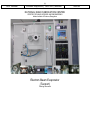
Electron Beam Evaporator
(Tecport)
Training document
Internal
[3]
Doc. Number
E-beam evaporator ( TECPORT) Manual
Contents
1 Descriptions and Specifications………………………………………………………………4
2 Safety…………………………………………………………………………………………….5
2.1 Safety Instructions ………………………………………………………………...5
2.2 Health Hazard……..………………………………………………………………..6
2.3 Special Notes ……………………………………………………………………....6
3 Operating Manual…………………………………………………………………………........7
3.1 Start Up ……………………………………………………………………………...7
3.2 Substrate Loading ……………………………………………………………….....8
3.3 System evacuation …………………………………………………………………8
3.4 Deposition ……………………………………………………………………………8
3.5 Substrate Unloading ………………………………………………………………..9
3.6 Shutting down the system ………………………………………………………....9
4 Process Recipe………………………………………………………………………………....10
4.1 Process Parameters ……………………………………………………………….11
4.2 Ion Source …………………………………………………………………………..12
4.3 Etching ………………………………………………………………………………13
4.4 Material …………………………………………………………………………......14
4.5 Deposition …………………………………………………………………………..18
4.6 Master Recipe ………………………………………………………………………19
Internal
[4]
Doc. Number
E-beam evaporator ( TECPORT) Manual
Internal
Chapter 1
Descriptions and Specifications
Electron-beam evaporation, frequently called "e-beam," uses a focused beam of electrons to heat the metal
for deposition. A controlled deposition of thin-films is achieved. Both dielectrics and metals can be
deposited using solid sources. The material is kept in a water-cooled crucible and exposed to the electron
beam, causing it to vaporize and condense on the wafers / samples. Oxygen gas can be bled into the
system during deposition to maintain the stoichiometry during deposition. Planetary substrate rotation
provides uniform deposition. Radiant heaters are provided for substrate heating. Option for Ion Assisted
deposition, co-deposition and Ion etching is also available.
Tool Specifications:
Tecport assembled:
- E gun Manufacturer: Temescal
- One 4 pocket hearth and one 6 pocket hearth.
- Pop-Top source
- Max Power 10kW
- Accelerating Voltage 4-8 kV
- Beam deflection 270deg
- Emission Current 0-1.5A
Programmable sweep controller.
Temescal Crucible indexer.
Substrate holder {6, 4, 3, 2 inch diameter}.
Planetary rotation with four holders.
Inficon IC6 deposition controller.
Ultimate Pressure ~2E-7 Torr.
Process Control using Symphony software provided by Tecport
Deposition rates from 1 Å/s to 199 Å/s.
Location: IISc, CeNSE, NNFC, Thin Films bay.
Primary Staff Contact: Chandrashekar S Kambar.
E-mail: [email protected]
Ph:
+91-9945833350
[5]
Doc. Number
E-beam evaporator ( TECPORT) Manual
Internal
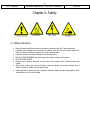
Chapter 2: Safety.
2.1 Safety Instructions
Read all relevant instructions before you operate any accessories of the E- beam evaporator.
Potentially lethal voltages may exist within this system, even with the main power switched off.
Failure to observe all safety precautions can result in personal injury.
Operators shall not enter areas intended for service access only.
HIGH VOLTAGE WARNING and caution signs are posted in conspicuous locations.
DO NOT WORK ALONE!
Remove rings, watches, bracelets, and any other metal jewelry before working around high
voltage.
When turning on the e-gun, make sure that the e-beam is centered on the source material. Do not
allow the e-beam to sweep onto the copper hearth.
Intense light will be emitted from the evaporation materials. Always use dark safety glasses / filter
window when you look in the chamber.
[6]
Doc. Number
E-beam evaporator ( TECPORT) Manual
Internal
2.2 Health Hazard
The condensates deposited on the tank walls of a vacuum system are generally in the form of
extremely fine particles.
Inhaling fine particles (powder) may cause damage to the lungs. To help prevent this, wear a
protective respirator mask with fine filter.
Some substances are toxic and inhaling them should be avoided. Take steps to ascertain whether
or not the material being deposited is a known toxic substance. Refer to the Material Safety Data
Sheets covering the evaporant (s) in question.
Certain powders (titanium, for instance) can cause flash fires when exposed to oxygen or other
oxidizers. Therefore, when opening the chamber door after a deposition cycle, exercise extreme
caution and allow time for the coating surface to oxidize. Breakage of some of the more reactive
condensates may be hazardous, even when the above precautions are observed. In this situation,
fire-protective clothing should be worn.
2.3 Special Notes
You must be qualified by NNFC Technologist/Tool owner to use this tool.
Wear clean lint-free gloves when you handle components in the chamber to prevent contamination
of the evaporation materials and its accessories.
Do not over fill the hearth/crucible with evaporation materials. If you do, molten materials can spill
out of the crucible, crack crucible liner and contaminate the e- beam source.
Do not continue the evaporation when source material is out. Continue to evaporate when source
material ran out will crack crucible liner. After evaporating for a while, if evaporation rate slows
down quite a bit. Stop the evaporation here! It is possible that the metal source is running out.
Only vacuum compatible materials are allowed in the system
When you are done with your work, always leave the chamber under vacuum.
Minimize the time the chamber is left at atmosphere, by preparing your samples in advance (i.e.
before or while venting). This should be done in order to reduce contamination and moisture
accumulation on chamber walls.
The color code for all the GUI screens is GREEN: ON or satisfied and GREY: OFF or not satisfied.
Set value is displayed in YELLOW and the present value in BLUE
Substrates will be exposed to secondary radiation as there may be production of X-rays due to the
high voltage electron beam. Radiation can damage MOSFET and Silicon based devices
Enter all the parameters in log book
In case of any complaint with the tool, enter in maintenance log as well as inform NNFC staff.
[7]
Doc. Number
E-beam evaporator ( TECPORT) Manual
Internal
Chapter 3: Operating Manual
3.1 Start Up
Check the logbook to verify if the last entry was okay.
Turn on the utilities required for the system
-
Water lines -First outlet then inlet (on the back panel of the system)
-
Gas lines {Inlet for O2 and Ar (on the back panel of the system)
-
System electrical power ON switch (on the right panel of the system)
Switch ON the UPS on the control panel of the system by pressing the power on button for 3 sec
Once the LEDs are all powered up (wait for 10 sec) switch ON the computer CPU
Once logged in the system, right click and open the SYMPHONY software on the desktop
This will also open IC6 window, which should be closed
After booting we have the welcome screen of the software Click on the symphony logo to get a
pop-up menu
Select the login option there, you will get a login window
Enter your username and password
After logging in the software again click on the Symphony logo and turn the control power ON
Switch ON IC6
Now the system is ready for loading
[8]
Doc. Number
E-beam evaporator ( TECPORT) Manual
Internal
3.2 Substrate Loading
Please make the time of system being open to atmosphere minimum, by preparing your samples in
advance (i.e. before venting).
Press the `Vent' button in the symphony window to vent the chamber.
The chamber will unlock itself with notification through a buzzer.
Clean the chamber using vacuum cleaner and IPA.
Place your samples/substrates onto the wafer carrier baskets, remove the baskets only if
necessary.
Make sure that the required materials are loaded in the correct pocket of the EB gun pocket.
Close the chamber door and hold it in that position for some time, i.e. till you hear the door clamp
being activated from inside.
Select the required recipe from process window on left side and load it to IC6.
3.3 System evacuation
Press the play button which is on the bottom of the window. You will get 3 confirmation windows,
press yes in all and the pumping starts. It takes anywhere between 2 to 3 hours for complete
pumping depending on the chamber health and the base pressure required.
3.4 Deposition
As the pressure nears the deposition pressure, switch on E-beam power supply, I-gun power
supply and IC6 is ON, as per the requirement.
Once the required parameters are satisfied, the tool gives a buzzer and starts deposition.
The elapsed time, layer no, material, thickness, power; deposition rate... is displayed on the
‘Process’ window on the left hand side.
The E-beam position can be adjusted using the hand-held remote. The other parameters that can
be changed are amplitude, frequency and waveform in both latitude and longitudinal direction.
Change the set pattern only if it’s really required.
Fill out Run-log sheet in logbook.
The status of the deposition is displayed on INFICON IC6 (top-right).
Once the deposition is over, the system automatically shuts down and will vent the chamber after
the mentioned time delay.(main valve close delay, vent delay will be taken from the process
parameter recipe).
[9]
Doc. Number
E-beam evaporator ( TECPORT) Manual
Internal
3.5 Substrate Unloading
Once the chamber is out of vacuum, remove the substrates out from the basket carefully and clean
the chamber (using vacuum cleaner and then with IPA).
Close the chamber door and hold it in that position for some time, i.e. till you hear the door clamp
being activated from inside
3.6 Shutting down the system
Close the system door and again start pumping (the chamber should always be kept in vacuum
(this is to prevent accumulation of moisture in chamber).
Once the system reaches the rough vacuum of e-3 range, stop pumping.
Turn the Control Power OFF from the symphony icon pop up list.
Exit the software, from the symphony icon pop up list.
Switch off the computer.
Switch OFF IC6 deposition controller.
Switch OFF KRI I-Gun discharge controller, Bias controller and Keeper Controller.
Switch OFF the power supply for the E-gun.
Turn off the UPS by long pressing the power button.
Press EMO.
Turn the system power switch to off position.
Shut the water line, first inlet and then outlet.
Turn off the gas lines.
[10]
Doc. Number
E-beam evaporator ( TECPORT) Manual
Chapter 4: Process Recipe
The recipe menu includes
Process Parameters
Ion Source
Etching
Material
Deposition
Main Process
Internal
[11]
Doc. Number
E-beam evaporator ( TECPORT) Manual
Internal
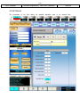
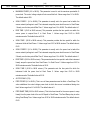
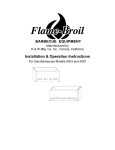
4.1 Process Parameters
The process parameters are included in this window. We have to enter the values for
Heater control during pumping down and during deposition
The rotation speed
Main valve close options
Vent delay time
Etching start options
Depositions start options.
The option for temperature control during and after deposition is in the next tab.
[12]
Doc. Number
E-beam evaporator ( TECPORT) Manual
Internal
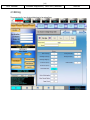
4.2 Ion Source
The parameters of Ion Gun during Ion assisted deposition have to be entered here
[13]
Doc. Number
E-beam evaporator ( TECPORT) Manual
4.3 Etching
The parameters for I gun during etching have to be entered here
Internal
[14]
Doc. Number
E-beam evaporator ( TECPORT) Manual
Internal
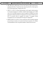
4.4 Material
Each material has a directory. The standard parameters will get automatically loaded as
we
select
a
material.
The
parameters
included
are
MATERIAL NUMBER. This is the reference tag given for each material in IC6
COMPOUND NAME. Name of the compound and this can be edited.
DENSITY (0.100 to 99.99 gm/cc). The default value is 10.00. This parameter is specific to the
material being deposited onto the Crystal. It is one of two
[15]
Doc. Number
E-beam evaporator ( TECPORT) Manual
Internal
parameters that relate the mass loading on the crystal to a thickness. Values range from 0.500 to
99.999. If a material is chosen from the Material Library the density is automatically entered. The
default value is 10.00.
Z-RATIO (0.100 to 15.000). This parameter is specific to the material being deposited. It is one of
two parameters that relate the mass loading on the crystal to a thickness. Values range from 0.100
to 15.000. If a material is chosen from the Material Library the Z-ratio is automatically entered. The
default value is 1.00. This parameter is superseded if Auto Z-ratio is selected in Source/Sensor
Set-Up. CONTROL LOOP 0, 1, 2. This parameter establishes the control loop algorithms
pertaining to either a slow responding source or a fast responding source. Permissible values are
0, 1, or 2. Select a 0 to choose the non-PID control loop, good for fast- and medium-speed
responding systems with high noise levels (e.g., an electron beam gun with or without a liner,
having large sweep amplitude of low frequency, 10 Hz or less). Select a 1 for the PI control loop,
good for fast, medium, or slow systems with medium noise levels (e.g., an electron beam gun with
medium sweep amplitude frequency, 20 to 100 Hz; also, sputtering and resistive sources). Select a
2 for the PID Control Loop, good for fast, medium or slow systems with low noise levels (e.g., an
electron beam gun with sweep off or at a high frequency, 100+ Hz; also, sputtering and resistive
sources).
PROCESS GAIN (0.01 to 100.0 Å/sec/ % power). This parameter determines the change in %
Power for a given rate deviation (dRate/dPower). The larger the process gain value, the smaller the
change in power for a given rate error. Values range from 0.01 to 100.00. The default value is
10.00.
PRIMARY TIME CONSTANT (0.010 to 200.00 sec). This is the evaporation source's time constant.
This value is defined as the time difference between the actual start of a change in rate and the
time at which 63% of the rate step is achieved. This value may be measured according to the
above criterion or it may be determined empirically. Values range from 0.010 to 200.00 seconds.
The default value is 1. This parameter is disabled if the CONTROL LOOP option parameter is set
to 0.
SYSTEM DEAD TIME (0.010 to 50.000 sec). This value is defined as the time difference between
a change in % power and the start of an actual change in rate. Values range from 0.010 to 50.000
seconds. The default value is 1.0. This parameter is disabled if the CONTROL LOOP option
parameter is set to 0.
[16]
Doc. Number
E-beam evaporator ( TECPORT) Manual
Internal
MAXIMUM POWER (0.0 to 99.9%). This parameter is used to set the maximum permissible %
power level. The control voltage output will not exceed this limit. Values range from 0.0 to 99.9%.
The default value is 90%.
SOAK POWER 1 (0.0 to 99.9%). This parameter is usually set to the power level at which the
source material just begins to melt. The instrument ramps the power level from zero to Soak Power
1 linearly over the time period Rise Time 1. Values range from 0.0 to 99.9%. The default value is 0.
RISE TIME 1 (00:00 to 99:59 min:sec). This parameter provides the time period over which the
source power is ramped from 0 to Soak Power 1. Values range from 00:00 to 99:59
minutes:seconds. The default value is 00:00.
SOAK TIME 1 (00:00 to 99:59 min:sec). This parameter provides the time period for which the
instrument holds at Soak Power 1. Values range from 00:00 to 99:59 minutes. The default value is
00:00
SOAK POWER 2 (0.0 to 99.9%). This parameter is usually set to the power level at which the
source material just begins to melt. The instrument ramps the power level from zero to Soak Power
2 linearly over the time period Rise Time 2. Values range from 0.0 to 99.9%. The default value is 0.
RISE TIME 2 (00:00 to 99:59 min:sec). This parameter sets the time period in which the instrument
linearly ramps the power level from Soak Power 1 to Soak Power 2. Values range from 00:00 to
99:59 minutes:seconds. The default value is 00:00.
SOAK TIME 2 (00:00 to 99:59 min:sec). This parameter sets the time period for which the
instrument holds the power level at Soak Power 2. Values range from 00:00 to 99:59
minutes:seconds. The default value is 00:00.
AUTOS SOAK 2 (Y/N).
FEED POWER (0.0 to 99.9%). This is one of three parameters used to affect a Feed Ramp. This
value establishes the control voltage power level at which the source is maintained during wire
feed. Values range from 0.0 to 99.9%. The default value is 0.
FEED RAMP TIME (00:00 to 99:59 min:sec). This is the time interval for the source power to ramp
linearly from the power level at the end of Deposit to Feed Power. The Feed Ramp relay is active
during Feed Ramp Time. Values range from 00:00 to 99:59 minutes:seconds. The default value is
00:00.
[17]
Doc. Number
E-beam evaporator ( TECPORT) Manual
Internal
FEED TIME (00:00 to 99:59 min:sec). This is the time interval for which the source power is
maintained at Feed Power. The wires Feed relay is active during Feed Time. Values range from
00:00 to 99:59 minutes:seconds. The default value is 00:00.
WEIGHT (1.0 to 400.0%). The Sensor Weight parameter is used to gauge the relative importance
of each sensor's measured rate in calculating a weighted average 'aggregate' rate. The default
value is 100%. If the WEIGHT parameter for a sensor is changed, the new WEIGHT for this sensor
will be used for subsequent calculations of the aggregate rate, if the sensor's OPTION is non-zero.
NOTE: This parameter affects the aggregate rate calculation. The aggregate thickness
accumulated thus far is not re-scaled based on the change to the weighting factor.
MASTER TOOLING (10.0 to 400.0%). This is a correction factor used for correlating the aggregate
rate and thickness accumulation on the crystal with the thickness accumulation on the substrate.
This thickness difference is due to the geometric distribution of material flux from the source.
[18]
Doc. Number
E-beam evaporator ( TECPORT) Manual
Internal
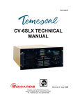
4.5 Deposition
To include a process deposition recipe, click on New and enter the new recipe name. Select the material
from the list of materials and the Ion source recipe and click on ‘Append to End’. This will insert one layer.
Include all the layers required. The Ion assist enable, final thickness, crucible number, e-beam gas, sweep
pattern number and crystal number has to be entered here. There are options to copy the layers as well.
[19]
Doc. Number
E-beam evaporator ( TECPORT) Manual
Internal
4.6 Master Recipe
Master Recipe Builder is the final step in the recipe writing. Click on New and enter a recipe name. It will
ask for Process Parameter, Ion Source Etching and Deposition. Select from the corresponding menu. We
have the option to disable ion assist, ion etching, deposition and trending. Save the recipe, Validate and
Preview. Now this will appear in the scroll down menu in the Recipe window in the left hand side.