1
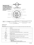
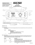
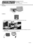
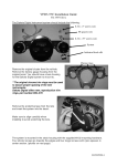
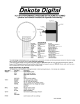
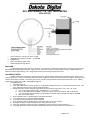
MCL-4000 SERIES 1-7/8” LED TACHOMETER
MCL-4027S/R
•
•
•
•
•
10 rpm resolution. (100 rpm res. above 10,000)
Adjustable warning point from 2200 – 14,600 RPM
Hi RPM recall
Fast or slow display update rates
Optional display dimming feature
MOUNTING
The MCL-4000 series gauge requires a round hole 1-7/8” diameter. It should be inserted into the opening from the front and
the U-clamp will be installed from the back. Tighten the two nuts on the U-clamp so that the gauge is secure. Gauge depth to the
back of the case is approximately 1-3/8”. Gauge depth including the mounting studs is about 2-1/8”.
TACHOMETER SETUP
The MCL-4000 series tachometer has three setup menus; cylinder setting, update speed, and warning point. Setup is done
using the green wire. There is a momentary push button switch supplied that can be mounted anywhere so setup and the hi rpm recall
function can be easily accessed. Connect the green wire to one side of the push button switch and the other side to +12V. Default
settings are 2 cylinder, slow update, 5000 RPM warning point.
TO ENTER SETUP:
1. start with the key off.
2. Press and hold the switch and turn the key on, the gauge should light and show “Lr1” as long as the switch is held. This
is the software code and may be used to identify the product.
3. Release the switch and the gauge will automatically scroll through the setup menus “CYL” “SPd” “ HI” “DnE”
a. “CYL” is the engine cylinder setting, selectable from 1 – 15 cylinders
b. “SPd” is the update rate of the display. Slow “SLo” is about 1/2 second and Fast “FSt” is 1/8 second.
c. “ HI” is the warning point at which the gauge will flash to indicate redline, settable from 2200-14,600 RPM.
d. “DnE” end of setup menus
4. When the desired menu is displayed press and release the switch
5. The current value for the setting should be displayed
6. To change the settings press and release the switch
7. Once the desired value is displayed press and hold the switch to save the changes
8. the display will jump to “DnE” indicating the new setting has been saved
9. Press and release the switch when “DnE” is displayed to exit and return to normal operations, or ….
10. The gauge will remain in setup and keep looping thought the menus until the power is cycled off then on.
MAN# 650190
POWER RED WIRE
Connect the red wire from the main harness to accessory power from the ignition switch.
***Never connect this to a battery charger alone. It needs to have a 12 volt battery connected to it. Battery chargers have an
unregulated voltage output that will cause the system to not operate properly.
GROUND BLACK WIRE & RING TERMINAL
The black wire is the main ground for the gauge. A poor ground connection can cause improper or erratic operation.
Connect the ground to a good chassis ground directly to battery ground. Also connect the ring terminal on the main harness to one of
the mounting studs after the clamp has been installed before the thumb nut is screwed on to secure the gauge. This provides a
ground for the case of the gauge.
TACHOMETER SIGNAL GRAY WIRE
The gray wire connects to the vehicle tach signal. On point type and pointless distributors connect to the negative side of the
coil. This will sometimes be labeled TACH or DIST. On distributorless ignition systems, connect to the tach output wire or to the
negative wire of one of the coils. On MSD ignition systems connect to the tach output terminal.
For tach signals integrated into a vehicle wiring harness, consult a service manual to determine the color code and location of
the tachometer signal. The tachometer signals from some engine computers require a weak 12 volt pull-up for correct operation of the
gauge. Tie the gray and white/red wires together if this is needed.
The tachometer is adjustable from 1 to 15 cylinder signals and setup is discussed above.
The gauge displays the engine rpmx10 from 300 – 9990 and rpmx100 for 10,000 – 18,000. 2500 rpm would be displayed as
“250” and 11,400 rpm would be displayed as “11.4”. The decimal point indicates the reading has changed from rpmx10 to rpmx100.
The gauge can be set for a slow update, which changes the displayed reading every 1/2 second, or for a fast update, which
changes the displayed reading every 1/8 second. The slow update rate is recommended for most applications since rapidly changing
numbers can be difficult to read.
***The tach may not read properly with dual fire ignitions
FUNCTION SWITCH & HI RPM RECALL GREEN WIRE
The function switch is connected with one wire to a +12 volt source and the other wire to the green wire from the tachometer
harness. The function switch is used for calibration and to recall the highest rpm reached since the last reset. Pressing and releasing
the function switch while the gauge is running will display “HI” and then the current high rpm. This will repeat every 2 seconds.
Holding the function switch for about 2 seconds will reset the high rpm. Pressing and releasing the switch will return the gauge back to
normal operation.
NIGHT DIMMING BLUE WIRE
Your display system has a dimming feature that reduces the display intensity. Normally the system is at full brightness for
daytime viewing. When the blue wire has +12 volts the display intensity will be reduced. Connect this to switch able +12V to enable
this feature. To have the system at full brightness all of the time, leave the blue wire disconnected.
TROUBLE SHOOTING GUIDE Please read this before calling Dakota Digital for technical assistance
Problem
Gauge will not light up
Gauge always flashes.
Gauge will not dim.
Possible cause
Red wire does not have power.
Black wire is not getting a good ground.
Gauge is damaged.
Cylinder setting is not set correctly
Loose connection on signal input
Poor ground connection.
Voltage or wiring problem in vehicle
harness.
Failing ignition system component
(more common on points style)
High warning point set too low.
Blue wire is not connected correctly.
Gauge remains dim at all times.
Blue wire is getting power all of the time.
Gauge will not go into the
SETUP mode.
Gauge displays “Er1”
Gauge displays “Er2”
Gauge displays “Er4”
Gauge displays “Er” followed by
a number.
Switch is not connected properly
Gauge lights up but does not
read correctly.
Cylinder setting is invalid, 1-15 cylinders
Update speed error, slow or fast
High RPM warning point error, 2200-14.6k
Multiple errors have occurred and the
error numbers have been added.
Solution
Connect to a location that has power.
Connect ground to a different location.
Return gauge for repair.
See “TACH SETUP” in manual to change setting.
Check signal input wire (gray wire)
Move gauge ground wire to different ground location.
Check wiring harness for loose/damaged wires and
check wire routing is not close to spark plug wires.
Check or replace ignition system components
Adjust the high warning points using setup menu.
Check wiring. Blue wire should have 12 volts when
dimming is desired.
Connect blue wire to +12v through a switch or leave
unconnected.
Verify correct connection of switch to +12V and
green wire.
See “TACH SETUP” in manual
See “TACH SETUP” in manual
See “TACH SETUP” in manual
For “Er3” see solutions for “Er1” and “Er2”
For “Er5” see solutions for “Er1” and “Er4”
For “Er6” see solutions for “Er2” and “Er4”
For “Er7” see solutions for “Er1”, “Er2” and “Er4”
MAN# 650190
Service and Repair
DAKOTA DIGITAL offers complete service and repair of its product line. In addition, technical consultation is available to help you work through any questions or
problems you may be having installing one of our products. Please read through the Troubleshooting Guide. There, you will find the solution to most problems.
Should you ever need to send the unit back for repairs, please call our technical support line, (605) 332-6513, to request a Return Merchandise Authorization
number. Package the product in a good quality box along with plenty of packing material. Ship the product by UPS or insured Parcel Post. Be sure to include the RMA number
on the package, and include a complete description of the problem with RMA number, your full name and address (street address preferred), and a telephone number where you
can be reached during the day. Any returns for warranty work must include a copy of the dated sales receipt from your place of purchase. Send no money. We will bill you after
repair.
Dakota Digital 24 Month Warranty
DAKOTA DIGITAL warrants to the ORIGINAL PURCHASER of this product that should it, under normal use and condition, be proven defective in material or
workmanship within 24 MONTHS FROM THE DATE OF PURCHASE, such defect(s) will be repaired or replaced at Dakota Digital’s option.
This warranty does not cover nor extend to damage to the vehicle’s systems, and does not cover removal or reinstallation of the product. This Warranty does not
apply to any product or part thereof which in the opinion of the Company has been damaged through alteration, improper installation, mishandling, misuse, neglect, or accident.
This Warranty is in lieu of all other expressed warranties or liabilities. Any implied warranties, including any implied warranty of merchantability, shall be limited to
the duration of this written warranty. Any action for breach of any warranty hereunder, including any implied warranty of merchantability, must be brought within a period of 24
months from date of original purchase. No person or representative is authorized to assume, for Dakota Digital, any liability other than expressed herein in connection with the
sale of this product.
4510 W. 61ST St. N., Sioux Falls, SD 57107
Phone: (605) 332-6513 FAX: (605) 339-4106
www.dakotadigital.com
[email protected]
©Copyright 2007 Dakota Digital Inc.
MAN# 650190