1
Cutler-Hammer
N EMA Contactors & Starters
March 2002
Contents
Description
Page
IT. Electro-Mechanical Line
33-2
33-4
Starters - Full Voltag e Non-reversing and Reversing . . . . . . . . . . . . . . . . .
33-7
ua
ls
Product Family Overview . . . . . . . . . . . . . . . . . . . . . . . . . . . . . . . . . . . . . . . .
Contactors - Full Voltag e Non-reversing and Reversing. . . . . . . . . . . . . . .
Supplement to Publication No. CA08102001 E.
ww
w
.E
lec
tri
ca
lP
ar
tM
an
Note:
CA03305001 E
33-1
.c
om
I'.:.T•N
For more information contact Cutler-Hammer at:
www.cutler-hammer.eaton.com
N EMA Contactors & Starters
Product Family Overview
Cutler-Hammer
.c
om
33_2
March 2002
IT. Electro-Mechanical line
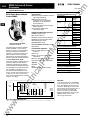
Eaton's Cutler-Hammer Intelligent
Technologies {IT.) Electro-Mechanical
line of Contactors and Starters is the
result of a substantial engineering,
manufacturing and marketing effort
involving extensive customer input,
combined with new advances in solid
state technology.IT. Electro-Mechanical
products have greatly increased
functionality, significantly reduced
size and utilize the benefits of 24V DC
control. The exclusive Pulse Width
Modulation (PWM) control and digital
microprocessor generate a minimized
DC value which reduces energy to the
contact block and provides the most
compact system available.
50100
IT. NEMA Overload Relay Setup and Troubleshooting Manual
50200
IT. NEMA Contactor and Starter User Manual
49400
IT. IEC Contactor and Starter User Manual
50102
IT. NEMA Overload Relay Quick Setup Guide
50140
IT. NEMA Non-reversing Contactor Size 00 and 0 Installation Guide
50150
IT. NEMA Non-reversing Contactor Size 1 Installation Guide
50160
IT. NEMA Non-reversing Contactor Size 2 Installation Guide
50170
IT. NEMA Non-reversing Contactor Size 3 and 4 Installation Guide
• UL Listed: UL File #E1491, Guide
#NLDX- Open, UL 508
IT. NEMA Non-reversing Contactor Size 5 Installation Guide
50141
IT. NEMA Reversing Contactor Size 00 and 0 Installation Guide
50151
IT. NEMA Reversing Contactor Size 1 Installation Guide
an
• Standard: Designed to meet or
exceed UL, NEMA and CSA
50180
50161
IT. NEMA Reversing Contactor Size 2 Installation Guide
50171
IT. NEMA Reversing Contactor Size 3 and 4 Installation Guide
50181
IT. NEMA Reversing Contactor Size 5 Installation Guide
50142
IT. NEMA Non-reversing Starter Size 00 and 0 Installation Guide
tM
Standards and Certifications
ua
ls
Instructional Leaflets
50152
IT. NEMA Non-reversing Starter Size 1 Installation Guide
50162
IT. NEMA Non-reversing Starter Size 2 Installation Guide
50172
IT. NEMA Non-reversing Starter Size 3 and 4 Installation Guide
50182
IT. NEMA Non-reversing Starter Size 5 Installation Guide
• NEMA Certification, CN60947-4-1
50143
IT. NEMA Reversing Starter Size 00 and 0 Installation Guide
• CSA Elevator Ratings
50153
IT. NEMA Reversing Starter Size 1 Installation Guide
50163
IT. NEMA Reversing Starter Size 2 Installation Guide
• CE
• NEMA ICS1, ICS2, ICS5
ISO 9002 Certification
50173
IT. NEMA Reversing Starter Size 3 and 4 Installation Guide
50183
IT. NEMA Reversing Starter Size 5 Installation Guide
ca
When you turn to Eaton's Cutler
Hammer Products, you turn to quality.
The International Standards Organiza
tion (ISO) has established a series of
standards acknowledged by 91 indus
trialized nations to bring harmony to
the international quest for quality. The
ISO Certification process covers 20
quality system elements in design,
production and installation that must
conform to achieve registration. This
commitment to quality will result in
increased product reliability and total
customer satisfaction.
ar
• CSA Certified: CSA File #156828,
Class #3211 04 Open, C22.2 No.14-95
lP
MCFI
Product Description
For copies of these and other publications, contact the Literature Fulfillment Center
at 800-957-7050, Fax: 877-840-2371 or find on-line at:
www.cutler-hammer.eaton.com(it.
tri
For International, call: (630) 377-9798 (English only), Fax: (630) 377-1753.
E-mail: [email protected]
ww
w
.E
lec
Mail: Cutler-Hammer Fulfillment Center
1750 Wallace Avenue
St. Charles, IL 60174-3404
For more information contact Cutler-Hammer at:
www. cutler-hammer.eaton.com
CA03305001 E
N EMA Contactors & Starters
Product Family Overview
Cutler-Hammer
33.3
.c
om
I'.:.T•N
March 2002
IT. Electro-Mechanical Line
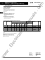
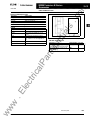
Catalog Number Selection (Open Components)
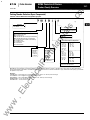
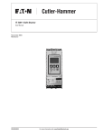
Table 33-1. IT. Electro-Mechanical Catalog Numbering System
N= NEMA
I
I
191
B
;-
�J! � 3 A
ua
ls
I
Standard
N
T
Overload Type
A= Standard
N= Contactor or Not Applicable
I
Configuration (Open Type)
02N= FVNR Coil Controller
03N = FVR Coil Controller
04N = Contact Block
05N=Solid-State Non-reversing Overload Relay
06N= Solid-State Reversing Overload Relay
071=Stand-Alone Solid-State Overload Relay
101= FVNR Starter
111 = FVNR Contactor
501=F V R Starter
511= FVR Contactor
I
Pole Selection
an
3=3-Pole
Overload Full Amperes Adjustment
tM
I
Designator (NEMA)
SA= Size 00
SO= Size 0
51= Size 1
52= Size 2
53= Size 3
54= S i z e 4
55= Size 5
ar
Frame Width
8=45 mm
C=54 mm
0=76 m m
E= 1 05 mm
F= 1 40 m m
I
I
ca
lP
XC= Coil Controller
XR= Overload
Note: When using the Catalog Numbering System for Eaton's Cutler-Hammer
(45 m m )
A= .25 - .8
B= .59 - 1 .9
c= 1 .4 - 4.4
D= 2. 8 - 9.0
G= 6.3 - 20
J= 1 0 - 32
(76 m m )
F = 5.0 - 1 6
H = 8.4 - 27
K= 1 4 - 45
N=31 - 1 00
(54 m m )
A= .25 - . 8
B=.59 - 1 .9
c= 1 .4 - 4.4
D =2.8 - 9.0
F= 5.0 - 1 6
H = 8.4 - 27
L= 1 6 -50
( 1 05 m m )
K= 1 4-45
M= 28 - 90
p=42 - 1 3 5
R= 63 - 200
( 1 40 m m )
p= 42 - 135
s= 84 - 270
T= 1 2 5 - 400
X=Contact Block, Coil Controller,
Contactor o r Not Applicable
IT. Electro-Mechanical products, care should be exercised to
assure that the Catalog Number for the Overload Relay aligns with the IT. Contact Block selected for type, frame size and ampacity, if purchased
as separate components.
tri
Examples:
N101 BSOJ3A- Full Voltage Non-reversing, Size 0 Starter with a 10-32 amp overload range
N111 FS5X3N- Full Voltage Non-reversing, Size 5 Contactor
N501 DS2K3A- Full Voltage Reversing Starter with a 14-45 amp overload range
ww
w
.E
lec
N02NCXCXNN- Coil Controller 54 mm
N 04 N BSAX3N- Contact Block S ize 00
CA0330500 1 E
For more information contact Cutler-Hammer at:
www.cutler-hammer.eaton.com
m
N EMA Contactors & Starters
Contactors- FV Non-reversing and Reversing
Cutler-Hammer
.c
om
33_4
March 2002
ll Electro-Mechanical Line
Product Description
Page
Product Family Overview
Product Description ....... 33-2
•il
Standards and
Certifications . . . ........ 33-2
Catalog Number
Selection ...... ........ 33-3
Contactors - Non-reversing
and Reversing
Product Description ....... 33-4
Features ................ 33-4
The IT. Electro-Mechanical Contactor
consists of an IT. Electro-Mechanical
Contact Block and IT. Electro-Mechanical
Coil Controller as a Full Voltage Non
reversing (FVNR) or Full Voltage
Reversing (FVR) device. Size 00 to Size
4 Contact Blocks combined with Coil
Controllers (factory or field assem
bled) are stand-alone Contactors. Only
the Size 5 Contactors have internal fac
tory assembled coil controllers.
Features
Product Selection . . . . .... 33-5
Technical Data.............. 33-10
Accessories ................ 33-12
Auxiliary Contacts ........ 33-14
Renewal Parts.............. 33-20
Dimensions ................ 33-22
• Size 00-5, 9-270A. 2-200 hp,
460V
• Easy field assembly of control
wiring- plug and unplug lockable
control connector
• Optional mounting plates for Size
00-5.
• Common accessories
• Long-life nickel silver tin contacts
provide excellent conductivity and
superior resistance to welding and
arc erosion
• Environmentally friendly materials
• Low wattage coils and minimal heat
dissipation
an
Description
• Built-in logic to provide either 2- or
3-wire control, eliminating the need
to provide and wire auxiliary con
tacts to seal in and interlock the con
tactor coils
ua
ls
Contents
• 24V DC Coil Control- safe, reliable
global standard
• Compact DC coil control- Size 00,
45 mm wide, 9A. 2 hp, 460V
tM
• Frame width (mm): 45, 54, 76, 105,
140
• No laminations, shading coils or
magnet noise
ar
• -40 to 149°F (-40 to 65°C)
operating temperature
lP
• No seal in auxiliary contacts
required- control wiring is not
needed between the contactor and
overload relay
• 2- or 3-wire control
Reversing Contactors
• Includes Reversing Power Wiring
• Mounting Plates for Size 00-2
• Exclusive internal electrical interlock
for reversing
• Field installed Reversing Kits
• Unique coil controller/overload
energizes both forward and reverse
contactors- one control point for
wiring
ww
w
.E
lec
tri
ca
• Conformal coated PWM board for
environmental toughness
• Front mounted Auxiliary Contacts:
1NO, 1NC, 2NO, 2NC, 1N0/1NC and
logic level
For more information contact Cutler-Hammer at:
www.cutler-hammer.eaton.com
CA03305001 E
NEMA Contactors & Starters
Contactors- FV Non-reversing and Reversing
March 2002
33-5
.c
om
Cutler-Hammer
ll Electro-Mechanical Line
Product Selection
When Ordering Specify
NEMA Size, Continuous Ampere Rating,
Voltage, kW/hp and Non-reversing or
Reversing
m
ua
ls
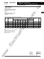
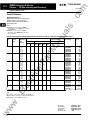
Note:
•An N111 (Size 00 - 4) consists of a n N04N
(Contact Block) and a n N02N.
•An N111F (Size 5) has a n internal coil
controller.
Table 33-2. Full Voltage 3-Pole DC-Operated Non-reversing Contactors G:J
Continuous
Ampere Rating
9
1
18
45
3
90
3
135
4
270
5
1
3
7-1 /2
15
-
-
-
-
10
15
75
Price
U.S.$
460V/
480V
50
100
2
5
575V/
600V
380V
2
5
1 - 1 /2
10
10
5
10
N111BSAX3N
N111BSOX3N
N111CS1X3N
25
25
25
N111DS2X3N
100
1 00
75
N111ES4X3N
50
200
50
200
50
N111ES3X3N
1 50
N111FS5X3N
1 64.
206.
241.
438.
7 1 4.
1 ,704.
3,694.
ww
w
.E
lec
tri
ca
lP
•If required, accessories are available on Page 33-12.
•NEMA Size 5 information is pre l i m i n a ry.
7-1 /2
30
40
Note:
•Three main contacts.
3
25
G) 24V DC coil voltage.
•c onsult factory for higher ampere ratings.
• I ntegral solid-state a uxi l i a ry hold-in c i rcuit.
3
7-1 /2
7-1 /2
3-Pole
Non-reversing
3-Phase
230V/
240V
1 - 1 /2
1 - 1 /2
2
2
27
1
2
1 /3
200V/
208V
tM
00
3-Phase
230V
an
1-Phase
115V
0
Max. UL
Horsepower (hp) 50 Hz
Max. UL Horsepower (hp) 60 Hz
ar
NEMA
Size
CA03305001 E
Accessories . . . . . . . . . .
Renewal Parts . . . . . . . .
Technical Data . . . . . . . .
Dimensions . . . . . . . . . . .
Discount Symbol . . . . . .
For more information contact Cutler-Hammer at:
www.cutler-hammer.eaton.com
.
. .
.
....
....
. . . .
....
Page 33-12-33-19
Page 33-20-33-21
Pages 33-10-33-11
Pages 33-22-33-26
1CD1
NEMA Contactors & Starters
Contactors- FV Non-reversing and Reversing
Culler-Hammer
.c
om
33_6
March 2002
ll Electro-Mechanical line
Product Selection
When Ordering Specify
NEMA Size, Continuous Ampere Rating,
Voltage, kW/hp, and Non-reversing or
Reversing
Note:
ua
ls
El
•An N511 (Size 00 - 4) consists of two N04N
(Contact Blocks), an N03N (FVR Coil
Controller), Mechanical Interlock, F a nni ng
Strips a n d M o u n t in g Plate, factory
assembled.
Table 33-3. Full Voltage 3-Pole DC-Operated Reversing Contactors CD
9
0
1
27
2
90
7-1!2
135
4
270
5
2
3
7-1 /2
3
45
2
3
1
1 /3
1
18
230V
15
-
-
-
-
0) 24V DC coil voltage.
Note:
• NEMA Size 5 information is prel i m i n a ry.
230V/
240V
1 - 1 /2
1 - 1 /2
3
3
7-1 /2
10
25
40
75
Price
u.s.$
7-1 /2
460V/
480V
575V/
600V
15
30
50
1 00
380V
2
5
10
2
5
10
25
50
100
200
25
50
100
200
1 - 1 /2
N511BSAX3N
5
N511BSOX3N
10
N511CS1X3N
25
N511DS2X3N
50
N511ES3X3N
75
N511ES4X3N
1 50
N511FS5X3N
425.
509.
587.
1,1 12.
1 ,836.
4,565.
8,222.
ca
•If requ i red, accessories are ava ilable on Page 33-12.
200V/
208V
tM
115V
3-Pole
Reversing
3-Phase
3-Phase
1-Phase
00
Max. UL
Horsepower (hp) 50 Hz
Max. UL Horsepower (hp) 60 Hz
ar
Continuous
Ampere Rating
lP
NEMA
Size
an
•An N511F (Size 5) consists of two N111F
(Contactors), an Internal Reversing Coil
Controller, Mechanical Interlock and Wi ring
H arness, factory assembled.
•Consult factory for h ig her ampere ratings.
•Integral solid-state a uxi l i a ry ho ld-in circuit.
ww
w
.E
lec
tri
•Three main contacts.
Accessories . . . .
Renewal Parts . .
Technical Data .
Dimensions . . . .
Discount Symbol
For more information contact Cutler-Hammer at:
www.cutler-hammer.eaton.com
...........
Page 33-12-33-19
Page 33-20-33-21
. . . . . . . . . . Pages 33-10-33-11
.
. . . . . Pages 33-22-33-26
. . . . . . . . 1CD1
...
. .
...
. .
.
.
.
.
. . .
.
. .
CA0330500 1 E
Ma rch 2002
ll Electro-Mechanical Line
Product Description
Description
Page
Product Family Overview
Product Description . . . . . .
33-2
Standards and
Certifications . . . . . . . . . .
33-2
Catalog Number
Selection . . . . . . . . . . . . .
33-3
Starters - Non-reversing
and Reversing
The IT. Electro-Mechanical Starter con
sists of an IT. Electro-Mechanical Con
tact Block and IT. Electro-Mechanical
Solid-State Overload Relay as a Full
Voltage Non-reversing (FVNR) or Full
Voltage Reversing (FVR) device. Size
00 to Size 5 Starters are factory or field
assembled.
Features
Product Description . . . . . .
33-7
Features . . . . . . . . . . . . . . .
33-7
Product Selection. . . . . . . .
33-8
• IP20 Finger Protection
• Unique Pulse Width Modulated coil
utilizes minimum energy
Accessories . . . . . . . . . . . . . . .
33-12
• Microprocessor based control
• Phase loss and current unbalance
protection
Dimensions . . . . . . . . . . . . . . .
33-25
• Standard selectable Trip Class 10, 20
(factory default) or 30- no individ
ual part numbers- no program
ming software
tM
33-14
33-20
• Easy field assembly of control
wiring- plug and unplug lockable
control connector
• DIN rail mountable Size 00-2
• Communication Interface with
Starter Network Adapter Product
(SNAP)
• Solid-state alarm output indication
• Retrofit mounting plates for Cutler
Hammer Business A200, Freedom
and Advantage
an
33-10
Auxiliary Contacts . . . . . . .
• Manual, Automatic or Remote Reset
• 2- or 3-wire control
• 24V DC control power- safe, reliable
global standard
Technical Data. . . . . . . . . . . . .
Renewal Parts. . . . . . . . . . . . .
• Motor running thermal utilization
indication
ua
ls
Contents
• Retrofit mounting plates for other
manufacturers
• Optional mounting plates with
"Ease of Installation" slotted hole
design
• Motor temperature and power-up
protection with thermal memory
• Stand-Alone Overload Relay- DIN
or panel mounting
• Front mounted auxiliary contacts
• Type 2 Coordination and "Weld
Free" devices
ar
• Ambient compensated
• Auxiliary Contacts: 1NO, 1NC,
2NO, 2NC, 1N0/1NC, logic level
(1N0/1NC)
• Built-in electronic interlock for FVR
units
• Conformal coated PWM board for
environmental toughness
lP
• Easily accessible mounting feet for
panel mounting
ca
• LED status indication- trip, trip
class, motor thermal state, reset,
overload state
• Unique "Alarm without Trip" option
for critical must run applications
tri
• Lockable overload cover protects
against unauthorized adjustment
and reset functions
• Minimal heat- no full voltage coils
-40° to 149°F (-40°- 65°C) operating
temperature
• Wide 3.2:1 current adjustment range
• Exclusive internal 24-bit floating
point math calculations with RMS
calibrated current measurement
• Highest immunity to ESD, harmonics
- minimal Total Harmonic
Distortion
ww
w
.E
lec
• No control wiring needed between
contactor and overload relay
eliminates seal in auxiliary contacts
•
CA0330500 1 E
For more information contact Cutler-Hammer at:
33_7
.c
om
NEMA Contactors & Starters
Starters- FV Non-reversing and Reversing
Cutler-Hammer
www.cutler-hammer.eaton.com
m
NEMA Contactors & Starters
Starters- FV Non-reversing and Reversing
Cutler-Hammer
.c
om
33_8
March 2002
ll Electro-Mechanical Line
Product Selection
When Ordering Specify
NEMA Size, Continuous Ampere Rating,
Voltage, kW/hp, Non-reversing or
Reversing and Overload Adjustment
Range (Amperes)
ua
ls
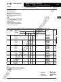
Note:
•An N101 (00 - 4) consists of an N04N
(Contact Block) a n d an N05N ( N on-reversing
Overload Relay).
•An N101 (Size 5 ) consists of a n N111F
(Contactor) and an N05N (No n -r eve rs ing
Overload Relay).
Table 33-4. Full Voltage N on-reversing DC-Operated, Open Type Starters (Size 00- 5),G:l with 3-Pole Solid-State Overload Protection
45
3
90
4
135
5
270
2
2
1
2
3
3
5
5
2
3
7-1 /2
1 4 -45
28 - 90
42 - 135
63 - 200
7-1/2
-
42 - 1 35
84 - 270
1 25 - 400
-
an
1 - 1 /2
3
1 4 - 45
28 - 90
42 - 1 35
63 - 200
575V/
600V
1-1/2
5.0 - 1 6
8.4 - 27
1 4 - 45
31-100
460V/
480V
1 - 1 /2
N101BSAA3A
N101BSAB3A
N101BSAC3A
N101BSAD3A
N101BSAG3A
5
N101BSOA3A
N101BSOB3A
N101BSOC3A
N101BSOD3A
N101BSOG3A
N101BSOJ3A
2
7-1 /
10
10
10
N101CS1A3A
N101CS1B3A
N101CS1C3A
N101CS1D3A
N101CS1F3A
N101CS1H3A
N101CS1L3A
10
15
25
25
25
N101DS2F3A
N101DS2H3A
N101DS2K3A
N101DS2N3A
15
25
30
50
50
50
N101ES3K3A
N101ES3M3A
N101ES3P3A
N101ES3R3A
-
40
50
100
1 00
75
N101ES4K3A
N101ES4M3A
N101ES4P3A
N101ES4R3A
75
100
200
200
1 50
N101FS5P3A
N101FS5S3A
N101FS5T3A
7- 1 /2
-
199.
1 99 .
1 99.
1 99 .
1 99 .
248.
248.
248.
248.
248.
248.
286.
286.
286.
286.
286.
286.
286.
518.
518.
5 1 8.
518.
846.
846.
846.
846.
1 ,9 1 7 .
1 ,9 1 7 .
1 ,9 1 7 .
1 ,9 1 7 .
4,678.
4,678.
4,678.
.E
G) 24V DC COli voltage.
Note:
Price
U.S.$
380V
tM
2
.25 - .8
.59 - 1 .9
1 . 4 - 4.4
2.8 - 9 .0
5.0-16
8.4-27
1 6 - 50
3-Pole
Non-reversing
3-Phase
230V/
240V
ar
27
200V/
208V
lP
1
3-Phase
230V
1
1 /3
.25-.8
. 59 - 1 .9
1 .4 - 4.4
2.8 - 9.0
6.3 - 20
1 0 - 32
Max.UL
Horsepower (hp) 50 Hz
ca
18
115V
.25 - .8
.59 - 1 .9
1 .4 - 4.4
2.8 - 9.0
6.3 - 20
9
0
1-Phase
tri
00
Max. UL Horsepower (hp) 60 Hz
Overload
Adjustment
Range
(Amperes)
Contiuous
Ampere
Rating
lec
NEMA
Size
•If required, accessories are ava ilable on Page 33-12.
•The standard IT. starter is for 3-phase applications only.
ww
w
• NEMA Size 5 i nformation is pre l i m i n a ry.
Accessories . . . . .
Renewal Parts . . .
Technical Data . .
Dimensions . . . . .
Discount Symbol .
For more information contact Cutler-Hammer at:
www.cutler-hammer.eaton.com
..........
..........
.
.........
Page 33-12-33-19
Page 33-20-33-21
Pages 33-10-33-11
Pages 33-22-33-26
..........
. . . . . . . . . . 1CD1
CA03305001 E
N EMA Contactors & Starters
Starters- FV Non-reversing and Reversing
33-9
.c
om
Cutler-Hammer
March 2002
IT. Electro-Mechanical Line
Product Selection
When Ordering Specify
NEMA Size, Continuous Ampere Rating,
Voltage, kW/hp, Non-reversing or
Reversing and Overload Adjustment
Range (Amperes)
m
ua
ls
Note:
•An N501 (Size 00-4) consists of two N04N
(Contact Blocks), N06N (Reversing Overload
Relay), Fan n in g Strips, Mechanical Interlock
and Mounting Plate.
an
•An N501F (Size 5) consists of two N111F
(Contactors), N06N (Reversing Overload
Relay), Fanning Strips, Mechanical Interlock
and Reversing Wi ring Ha rness.
Table 33-5. Full Voltage Reversing DC-Operated, Open Type Starters (Size 00- 5), CD with 3-Pole Solid-State Overload Protection
1
27
2
45
3
90
4
5
.25 - . 8
.59 - 1 .9
1 .4 - 4.4
2.8 - 9.0
6.3 - 20
1 0 -32
.25 - .8
.59 - 1 .9
1 .4 - 4.4
2.8 - 9.0
5.0 - 1 6
8.4 - 27
1 6 - 50
5.0 - 1 6
8.4 - 27
1 4 - 45
31 - 1 00
1
2
135
270
200V/
208V
1
1-1/2
2
3
3
7-1 /2
1 4 - 45
28 - 90
42 - 1 35
63 - 200
1 4 - 45
28 - 90
42 - 1 35
63 - 200
42-135
84 - 270
1 2 5 - 400
3-Pole
Reversing
230V/
240V
1 - 1 /2
460V/
480V
575V/
600V
2
2
380V
1 - 1 /2
N501BSAA3A
N501BSAB3A
N501BSAC3A
N501BSAD3A
N501BSAG3A
3
5
5
N501BSOA3A
N501BSOB3A
N501BSOC3A
N501BSOD3A
N501BSOG3A
N501BSOJ3A
10
10
10
N501CS1A3A
N501CS1B3A
N501CS1C3A
N501CS1D3A
N501CS1F3A
N501CS1H3A
N501CS1L3A
N501DS2F3A
N501DS2H3A
N501DS2K3A
N501DS2N3A
5
2
7-1 /
10
15
25
25
25
15
25
30
50
50
50
-
-
40
50
1 00
1 00
75
N501ES4K3A
N501ES4M3A
N501ES4P3A
N501ES4R3A
-
-
75
1 00
200
200
1 50
N501FS5P3A
N501FS5S3A
N501FS5T3A
3
7-1 /2
7-1 / 2
Price
U.S.$
3-Phase
tM
18
1 /3
3-Phase
230V
ar
0
.25 - .8
. 59 - 1 .9
1 .4 - 4.4
2.8 - 9.0
6.3 - 20
1-Phase
115V
Max. UL
Horsepower (hp) 50 Hz
lP
9
Max. UL Horsepower (hp) 60 Hz
.E
lec
00
Overload
Adjustment
Range
(Amperes)
ca
Contiuous
Ampere
Rating
tri
NEMA
Size
N501ES3K3A
N501ES3M3A
N501ES3P3A
N501ES3R3A
CD 24V DC coil voltage.
474.
474 .
474.
474.
474.
562.
562.
562.
562.
562.
562.
641 .
641 .
641 .
641 .
641 .
641 .
641 .
1 ,208.
1 ,208.
1 ,208.
1 ,208.
1 ,995.
1 ,995.
1 ,995.
1 ,995.
4,867.
4,867.
4,867.
4,867.
9,345.
9,345.
9,345.
Note:
•If required, accessories are available on Page 33-12.
•The standard IT. starter is for 3-phase applications only.
ww
w
• NEMA Size 5 information is pre l i m i n a ry.
CA03305001 E
Accessories . . . . . . . . . . . . . .
Renewal Parts . . . . . . . . . . . . .
Technical Data . . . . . . . . . . . .
Dimensions . . . . . . . . . . . . . . .
Discount Symbol . . . . . . . . . .
For more information contact Cutler- Hammer at
www.cutler-hammer.eaton.com
Page 33-12-33-19
Page 33-20-33-21
Pages 33-10-33-11
Pages 33-22-33-26
1CD1
.c
om
Cutler-Hammer
N EMA Contactors & Starters
Technical Data
33_10
March 2002
IT. Electro-Mechanical line
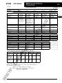
Table 33-6. Specifications
I Size 00, 0
Overall Dimensions in Inches (mm} GJ- wx
hx d
1 .8 x4.4x 2.4
(45x 1 1 1 x60)
Non-reversing
Contactor
I Size3,4
I Size2
I Size 1
2 . 1 x4.5x2.4
(54x 1 1 3x60)
3.0 X 5.9 X 3 . 1
(76 X 1 50 X 79)
4.1 X 8.0 X 3.5
( 1 05 X 203 X 90)
3.0 X 5.9 X 3.1
(76 X 1 50 X 79)
4.1 X 8.0 X 3.5
( 1 05 X 203 X 90)
5.7 X 1 9.4 X 7.0
( 1 45 X 492 X 178)
6.7
(3.05)
20.0
(9. 1 )
7.1
(3.20)
27.0
( 1 2.3)
Reversing
Contactor
3.8 X 5.9 X 2.7
(96 X 149 X 69)
4.5 X 5.9 X 2.6
( 1 1 4 x 1 49 x 67)
6.2 X 7.4 X 3.3
( 1 58 X 1 88 X 84)
Reversing
Starter
3.8 X 5.9 X 2.7
(96 X 149 X 69)
4.5 X 5.9 X 2.6
( 1 14x 1 49x67)
6.2 X 7.4 X 3.3
( 1 58 X 188 X 84)
Non-reversing
Contactor
.7
(.31)
.9
(.42)
2.8
( 1 .27)
Non-reversing
Starter
.9
(.40)
1 .2
(.53)
2.9
( 1 .32)
1 .8 X 4.4 X 2.4
(45 X 1 1 1 X 60)
Non-reversing
Starter
2 . 1 x4.5x2.4
(54x 1 1 3x60)
We1ghts m lb. (kg}
2.6
( 1 .17)
2.0
(.90)
2.6
( 1 .20)
7.1
(3.20)
.95 X 2.88
(24 X 73)
h
Non-reversing
Contactor
1 .33x4
(33.8 X 1 0 1 )
1 .46 X 4. 1 0
( 3 7 X 1 04)
Non-reversing
Starter
1 .33 X 4.62
(33.8 X 1 1 7.3)
1 .46 X 5.04
(37 X 1 28)
Reversing
Starter
3. 1 5 X 5.36
(80 X 136)
Panel-Vertical
Yes
DIN Rail Mountable
Yes®
Panel-Horizontal
Yes
Yes
Yes
-40° to + 1 49°F
(-40° to +65°C)
-40° to + 1 49°F
(-40° to +65°C)
YesC2J
Temperature
Operating
I
I 690V
Insulation Voltage (U1}
I
1 6 kV
Impulse W ithstand Voltage (Uimp}
Electrical life ®JJ
AC-2, AC-3 (@ max. amps.)
1 ,000,000 - 3,000,000
AC-4 (@ max. amps.)
AC-4
Operating Current (le)
48.0
(21 .8)
1 .33x4. 1 4
(33.8 X 1 05)
Consult factory
5.51 X 6.89
( 1 40 X 1 75)
7.88 X 9.06
(200 X 230)
1 .33 X 4 . 1 4
(33.8 X 1 05)
Yes
Yes
Yes
Yes@
No
No
Yes
-40° t o + 149°F
(-40° to +65°C)
-58° to + 176°F
( -50° to +80°C)
Yes
-40° to + 1 49°F
(-40° to +65°C)
-58° to + 176°F
( -50° to +80°C)
I 690V
I 690V
1 8,000,000
1 8.ooo.ooo
1 6 kV
1 6 kV
Yes
-40° to + 149°F
(-40° to +65°C)
-58° to + 1 76°F
(-50° to +80°C)
I 690V
1 6 kV
1 5,000,000
800,000 - 2,000,000
800,000 - 1 ,500,000
500,000 - 1 ,000,000
50
85
1 30
250
TBD
32
50
100
200
TBD
32
50
1 00
1 50
TBD
24V DC
24V DC
24V DC
lec
AC-2, AC-3
Operating Cu rrent (le)
1 1 0,000,000
1 1 .8x 1 9 .4x7.2
(300 X 492 X 1 83)
1 ,000,000 - 2,000,000
Current Ratings@ 480V Maximum
AC-1
Thermal Current lth
I 690V
tri
1 10,000,000
Mechanical life
-58° to + 1 76°F
(-50° to +80°C)
ca
-5SO to + 176°F
(-50° to +80°C)
Storage
3 . 1 5 X 5.36
(80 X 1 36)
1 1 .7 X 1 3.9 X 7.2
(296 X 354 X 1 83)
55.0
(25.0)
7.88 X 9.06
( 200 X 230)
.95 X 2.88
(24x 73)
5.5 X 1 3 .9 X 7.0
( 1 40 X 354 X 178)
1 6.8
(7.60)
5.51 X 6.89
( 1 40 X 1 75)
lP
. .
Mountmg Pos1t10ns
3. 1 5 X 5.36
(80 X 136)
ar
3. 1 5 X 5.36
(80 X 136)
Reversing
Contactor
1 6.9
(7.67)
6.9
(3.13)
1 .9
(.86)
Mountmg Hole Spacmg m Inches (mm}- wx
8.5 X 9.5 X 3.8
( 2 1 6 X 242 X 97)
an
Reversing
Starter
8.5 X 9.5 X 3.8
(2 1 6 X 242 X 97)
tM
Reversing
Contacto r
I Size 5
ua
ls
I Description
.E
Operat1on Performance
Coil Voltage (nominal)
24V DC
24V DC
Coil Insulation Rating
1 80°C
1 80°C
Drop-Out Time (ms) 0
5
5
Coil Operating
Voltage Range (V DC)
Pull-In Time (ms) 0
I
w
Mechanical Operatmg Rate
20 - 28
14
1 3/sec
20 - 28
14
I 3/sec
Cil Auxi l i a ries add .9 1 " (23 m m ) to depth for sing le, .50 " (30 mm ) for d u a l .
20 - 28
1 80°C
24
11
I 2 /sec
20 - 28
1 80°C
31
16
I 2 /sec
20 - 28
1 80°C
TBD
TBD
1 1 /sec
C2J N o n-reversing contactors and starters only.
ww
0 See Technical Data in Publication N o . CA03403002E, Life-Load Curves, for maxi m u m operations per frame size at va rious amperes.
-� Exc l u d i ng debounce time of 50 ms.
(5) Prel i m i n a ry data.
For more information contact Cutler-Hammer at: www.cutler-hammer.eaton.com
CA0330500 1 E
N EMA Contactors & Starters
Technical Data
March 2002
IT. Electro-Mechanical line
1 4 -8 AWG
( 1 .5 - 1 0 mm2)
Power Terminals
.45 "( 1 1 mm)
Strip Length
20 lb-in (2.2 Nml
per 1 4 - 10 AWG
( 1.5 - 6 mm2) ;
25 I b-in (2.8 Nml per 8
AWG ( 1 0 mm2)
Torque (max.)
Driver
35 I b-in (4.0 Nm)
per 1 4 - 10 AWG
( 1 .5 -6 mm2) ;
40 I b-in (4.5 Nml per 8
AWG ( 1 0 mm2) ;
45 I b-in (5.0 N m ) per 6
- 4 AWG ( 1 6 mm2)
4 5 l b -i n (5. 0 Nml
250 I b-in (28 Nml
550 I b-in (62 N m )
22 - 1 2 AWG
(.5 - 25 mm21
5/32 " (4 mm) Hex Key
22 - 1 2 AWG
( .5 - 25 mm2 )
5/1 6 "(8 mm) Hex Key
5/1 6 " (8 mm) Hex Key
. 5 "( 1 2 mml
22 - 1 2 AWG
(.5 - 25 mm2 )
Control Termi nals
(+ a n d -I
1 4 -12 AWG
( 1 . 5 - 2. 5 mm2 )
1 4 - 1 2 AWG
( 1 . 5 -2.5 mm2 )
Torque I b-in ( N m )
4.5 lb-in (0.5 Nml
4.5 I b-in (0.5 N m )
1
1
Environmental
1 5G
1 5G
Shock
Vi brati on
Pollution Deg ree
3
3
Altitude !i�
2000 Meters
2000 Meters
1
Cmls
Pull-In Ti me (ms) - Excluding debounce time of 50 ms
1 3.3
In cl u ding debou nce ti me @ 24V
DC
Drop-Out Time-Excluding
debounce time of 50 ms
'·
63.3
37
1
.25 "(7 mml
1 5G
5G
5G
1
1
26.9
2000 Meters
32.8
65.3
7 1 .6
82.8
95
27
XJN
N_11A
N_11B--XJN
N_01B
3A
N_11C- -X3N
A
B
B
3A
N_01C
N--1D---3N--1E__ _3_
N--1F___3_
'·
mm
27
45
45
54
Wattage
Amps
1 .3
3.7
3.2
4.2
.0 54
.15
.13
.18
c
c
D
E
F
'j)
@
3.6
5.0
5.6
54
76
1 05
140
.15
.21
.23
Inrush
Wattage
20
80
80
90
90
130
140
0
Amps
Duration
(msecs)
.83
3.3
3.3
3.8
30
50
50
50
50
65
85
3.8
5.4
5.8
@
Cf\
_ in dicates missing digit/character of the Cata log N u m ber; may have m u lti p l e values.
Consult facto ry.
.E
·'
Sealed In
tri
Frame
lec
Catalog
Number·':
Note: At other temperatures expressed in oc, for either inrush or sealed, use the 20°C
value from the table in the following:
ww
w
Watts=W2o [1 . 1 - .005(T) a n d Amps= A20 [1 . 1 - .005(T) ]
For example,i n rush requirements for a D Frame Star ter at -25°C would be:
WattS= 1 30 [1 . 1 - .005 (-25) ]= 1 60
Amps= 5.4 [1 . 1- .005 (-25) ]= 6.6
CA0330500 1 E
For more information contact Cutler-H a m mer at:
1 5G
5G
2000 Meters
Table 33-7. 24V DC Power Supply Requirements@ &a•F (20•C) (see Note below)
Contactor/Starter Size
.25 " (7 m m )
3
2 1 .6
1 9.8
1
3
1 5.3
23
Above 2000 meters, consult factory.
4.5 lb-in (0.5 Nml
2000 Meters
1 3. 8
1 2. 2
4.5 I b-in (0.5 Nml
3
19.2
22 - 1 2 AWG
(.5 - 25 mm2 )
4.5 I b-in (0.5 Nml
.25 " (7 mm)
ca
@ 26.4V DC
22 - 1 2 AWG
(.5 - 25 mm2 )
1 4 - 1 2 AWG
( 1 .5 -2.5 mm2 )
1
lP
17.2
@ 20.4V DC
@ 24.0V DC
1 .5 " (40 mml
1 4 - 1 2 AWG
( 1 . 5 - 2.5 mm2 )
ar
1
.8 " (21 mm)
(2) 4 AWG -250MCM
( 1 6 -1 20 mm2)
1 4 - 1 2 AWG
( 1 .5 - 2.5 mm2 )
1 5G
5G
5G
EMC Environment
.7 "( 1 8 m m )
tM
.25 " (7 mm)
.25 " (7 mm)
Strip Length
(2) 6 - 3/0 AWG
( 1 6 - 70 mm2)
4 AWG - 600MCM
( 1 6 -300 mm2)
(2) 1 4 -2 AWG
( 1 .5 -25 mm2)
Control Terminals
Conductors per
termi nal
6 AWG - 250MCM
( 1 6 - 1 20 mm2)
I Size 5
(2) 1 4 - 6 AWG
( 1 .5 - 1 6 mm2)
3 mm Hex Key
2.5 mm Hex Key
I Size 3,4
1 4 - 1 AWG
( 1 .5 - 35 mm2)
14 - 4 AWG
( 1 .5-16 mm2)
(2) 1 4 - 1 0 AWG
( 1.5 - 4.0 mm2)
2 Conductors per
terminal
I Size 2
I Size 1
ua
ls
I Size 00,0
AWG Wire Range (Stranded or Solid)
an
I Description
Table 33-6. Specifications, continued
33-11
.c
om
Cutler-Hammer
www.cutler-hammer.eaton.com
1
m
Cutler-Hammer
NEMA Co�tactors & Starters
Accessones
.c
om
33_12
March 2002
ll Electro-Mechanical line
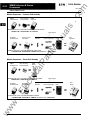
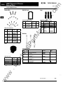
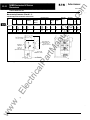
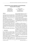
Modular Components- Contactor Field Assembly
FVNR
Non-reversing
Coil Controller
Contactor
El
EXAMPLE FOR A FULL VOLTAGE NON-REVERSING CONTACTOR:
N02NCXCXNN
(2) NEMA
=
N111CS1X3N
Interlock
.t:��··
.
+
.
I
I Mechanical
Reversing Coil
Controller
Contact Blocks
Reversing Kit
I
+
(2) Fanning Strips
Mounting
Plate
an
+
+
+
FVR
Contactor
-
tM
N04NCS1X3N
ua
ls
NEMA
Contact Block
Figure 33-1. Modular Contactor Assembly
NEMA
Contact Block
ca
+
tri
.
5�
FVNR
Starter
Non-reversing
Overload Relay
..
�
lP
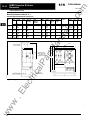
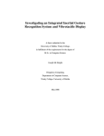
Modular Components- Starter Field Assembly
ar
EXAMPLE FOR A FULL VOLTAGE REVERSING CONTACTOR:
(2) N04NCS1X3N + N03NCXCXNN + EMRKTC (REVERSING KIT)= N511CS1X3N
Reversing Kit
(2) NEMA
lec
EXAMPLE FOR A FULL VOLTAGE NON-REVERSING STARTER:
N04NCS1X3N + N05NCXRL3A = N101CS1L3A
Reversing
Overload Relay
.E
Contact Blocks
+
I Mechanical
Interlock
I
I
(2) Fanning Strips
+
Mounting
Plate
+
FVR
Starter
-
EXAMPLE FOR A FULL VOLTAGE REVERSING STARTER:
(2) N04NCS1X3N
+
N06NCXRL3A
+
EMRKTC (REVERSING KIT)= N501CS1L3A
ww
w
Figure 33-2. Modular Starter Assembly
For more information contact Cutler-Hammer at:
www.cutler-hammer.eaton.com
CA0330500 1 E
NEMA Contactors & Starters
Accessories
March 2002
IT. Electro-Mechanical Line
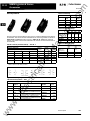
NEMA Contact Block
I
I
SIZE
00
0
1
2
3
4
Amperes
9
18
27
45
90
135
I
Catalog
Number
N04NBSAX3N
N04NBSOX3N
N04NCS1X3N
N04NDS2X3N
I
I Size
Non-reversing
-
N04NES3X3N
N04NES4X3N
-
00
0
N02NBSAXNN
N02NBSOXNN
N02NCS1XNN
N02NDS2XNN
1
2
3
4
5
-
N02NES3XNN
N02NES4XNN
N02NFS5XNN
+
+
N05N
=
N06N
=
N 1 0 1 ; N04N
N501 ; N04N
+
+
N02N
N03N
=
=
00
0
1
2
N 1 1 1 (45 - 1 40 mm )
N5 1 1 (45 - 1 40 m m )
tM
• N04N
I PriceU.S.$
-
Reversmg
Note:
•N04N
I Catalog Number
m
Table 33-10. NEMA Coil Controller - Non-reversing
Price
U.S.$
an
Table 33-8. NEMA Contact Block
ua
ls
NEMA Coil Controller
33-13
.c
om
Cutler-Hammer
3
4
5
-
N03NES3XNN
N03NES4XNN
EMUCCF
-
ar
NEMA Solid-State Overload Relay- Non-reversing
N03NBSAXNN
N03NBSOXNN
N03NCS1XNN
N03NDS2XNN
lP
NEMA Overload Relay- Reversing
Table 33-9. NEMA Solid-State Overload Relay - Non-reversing
.25 - .8
.59 - 1 .9
1 .4 -4.4
2.8 - 9.0
00
6.3 - 20
1 0 - 32
0
.25 - .8
.59 - 1 .9
1 .4 - 4.4
2.8 - 9.0
5.0-16
8.4-27
1 6-50
3
4
42 - 1 35
63 - 200
42 - 1 35
63 - 200
42 - 135
84 - 270
1 25 - 400
ww
w
5
5.0 - 1 6
8.4 - 27
1 4 - 45
3 1 - 100
.E
2
CA03305001 E
Price
U.S.$
N05NBSAA3A
N05NBSAB3A
N05NBSAC3A
N05NBSAD3A
N05NBSOG3A
N05NBSOJ3A
N05NCS1A3A
N05NCS1B3A
N05NCS1C3A
N05NCS103A
N05NCS1F3A
N05NCS1H3A
N05NCS1L3A
lec
1
Catalog
Number
ca
Overload
Adjustment Range
(Amperes)
tri
Size
N05NDS2F3A
N05NDS2H3A
N05NDS2K3A
N05NDS2N3A
N05NES3K3A
N05NES3M3A
N05NES4P3A
N05NES4R3A
N05NFS5P3A
N05NFS5S3A
N05NFS5T3A
Table 33-11. NEMA Overload Relay - Reversing
-
Size
-
-
00
-
0
1
-
-
-
2
-
-
3
4
5
Overload
Adjustment Range
(Amperes)
.25 .8
.59 - 1 .9
1 .4 - 4.4
2.8 - 9.0
Catalog
Number
Price
U.S.$
N06NBSAA3A
N06NBSAB3A
N06NBSAC3A
N06NBSAD3A
6.3 - 20
1 0 -32
N06NBSOG3A
N06NBSOJ3A
.25 - .8
.59 - 1 .9
1 .4 - 4.4
2.8 - 9.0
5.0 - 1 6
8.4 - 27
1 6 - 50
N06NCS1A3A
N06NCS1B3A
N06NCS1C3A
N06NCS103A
N06NCS1F3A
N06NCS1H3A
N06NCS1L3A
5.0 1 6
8.4 - 27
1 4 - 45
3 1 - 1 00
N06NDS2F3A
N06NDS2H3A
N06NDS2K3A
N06NDS2N3A
1 4 - 45
28- 90
N06NES3K3A
N06NES3M3A
42 - 135
63-200
N06NES4P3A
N06NES4R3A
42 - 135
84 - 270
1 25 - 400
N06NFS5P3A
N06NFS5S3A
N06NFS5T3A
Discount Symbol . . . . . . . . .. . . . . . . . . . . . . .. .
For more information contact Cutler-Hammer at:
www.cutler-hammer.eaton.com
-
-
-
-
-
-
-
1CD1
Cutler-Hammer
NEMA Co�tactors & Starters
Accessones
.c
om
33_14
March 2002
IT. Electro-Mechanical Line
Table 33-14. IEC Ratings
Auxiliary Contacts
AC-15
DC-13
Ue Voltage
24
48
m
1 25
5
2.5
Ue Voltage
1.1
.55
le
Amps.
48
8
240
4
1 20
6
440
2
ua
ls
250
le
Amps.
Table 33-15. NEMA A600 Ratings
Current
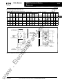
Auxiliary Contacts are available for mounting on IT. Electro-Mechanical Contactors
and Starters. The various choices available for non-reversing models are shown in
Tables 33-12 and 33-13, and their ratings in Tables 33-14-33-16. For reversing
models, the number of auxiliaries indicated is for each of the contactors/starters in
the assembly.
Size 2
Size 3,4
3
3
3
2
2
3
2
2
3
240
480
600
Make and
Interrupting
60
30
15
12
Conti nuous
10
Break
an
EMA13
EMA14
1 N0- 1 NC
EMA15
3
2N O
EMA16
3
Logic Level
1 N0-1 NC
EMA70
3
3
3
2
3
3
2
2
1 NO
1 NC
3
3
Price
u.s.$
20.90
20.90
28.00
ar
3
3
Catalog
Number
Contact
Type [7]
2NC
EMA17
lP
3
Size 1
tM
Top Mounted (Maximum Circuits per Contactor/Starter)
Size 00,0
120
Thermal
6
10
�
3
1 .5
10
10
10
10
1 .2
10
10
Table 33-16. NEMA P300 Ratings
Table 33-12. Auxiliary Contact Availability - Sizes 00- 4
Contactor/Starter Size
AC Voltage
28.00
I
Current
Make and
Interrupting
Break
Continuous
Thermal
DC Voltage
___--1
.� :..__
,::.� ..::. :..:. .::
,_
125
250
1.1
1.1
5
5
1
.55
5
.55
5
28.00
33.00
\1':, One EMA70 contact may be used in the center position in conjunction with two EMA15, EMA16 o r
EMA17 contacts i n the center positions.
3
1:0
N
r� '1f
NO
NC
14
22
EMA16
13
1 1
))
NO
14
23
NO
24
tri
1
EMA 1 5
Figure 33-3. Connecting Diagram - Sizes 00- 4
EMA70
EMA17
, r �, �'I( f�c
ca
EMA14
EMA13
NC
NC
12
22
N
Table 33-13. Auxiliary Contact - Size 5
1
1
3
Description
Catalog
Number
1 NO
Base auxiliary (max. 1 per side)
EMASB13
1 NO
Base auxil iary (max. 1 per side)
Base auxil iary (max. 2 Add-on auxiliary
per side) EMAS B 1 3 or EMAS B 1 5 required
.E
2
Contact
Type !71
1 N0-1 NC
1
2
lec
Front or Side Mounted 0- Maximum (141 Total Circuits
Size 5
1 NC
1 N0 - 1 N C
1 N0- 1 NC
. .
Base auxi liary (max. 2 Add-on auxil iary
per side) EMAS B 1 3 or EMAS B 1 5 required
Base auxiliary (max. 1 Add-on auxil iary
per side) EMAS B 1 3 or EMAS B 1 5 required
Front mou nted (max. 3)
EMASB15
Price
U . S. $
43.00
43.00
EMASA13
43.00
EMASA14
58.00
EMASA15
58.00
EMA70
33.00
ww
w
Cii Maximu m (3) auxi liaries per side .
Discount Symbol . . . . . . . . . . . . . . . . . . . . . . . .
For more information contact Cutler-Hammer at:
www.cutler-hammer.eaton.com
1CD1
CA03305001 E
NEMA Co�tactors & Starters
Accessones
March 2002
IT. Electro-Mechanical line
Reversing Kits
Mounting Plates and DIN Rails
33-15
.c
om
Cutler-Hammer
Includes Fanning Strips, Mechanical Interlock, Mounting
Plate and hardware.
Table 33-19. Reversing Kits
Description
00 ,0
For Contactor and Starter
1
For Contactor and Starter
3, 4
Catalog
Number
1
2
3, 4
5
Stand-Alone
Solid-State
Overload Panel/
DIN
Catalog
Number
Catalog
Number
Price
u.s.$
Price
U . S. $
-
EMA10B
-
EMA11B
-
EMA9C
-
EMA10C
-
EMA11C
-
EMA9D
-
EMA10D
-
EMA11D
-
EMA9E
-
EMA10E
-
EMA11E
EMA9F
-
EMA10F
-
EMA11F
Table 33-18. Fanning Strips
Wye-Delta
00 ,0
EMFRB
-
EMFWB
-
EMFRC
-
EMFWC
-
EMFRD
-
3, 4
5
EMFRE
EMFRF
-
EMFWD
-
-
EMFWE
-
-
EMFWF
-
ww
w
.E
lec
Consult factory.
EMRSKF
tri
Ring Terminals
-
lP
2
-
EMRCKF
Price
U.S.$
ca
1
Catalog
Number
-
EMRKE
-
Reversing
Price
U . S. $
-
EMRKD
-
NEMA
Size
Catalog
Number
EMRKC
Note: Also order separately the appropriate contact blocks and
overload relay.
EMA9B
Fanning Strips
For Starter
5
-
tM
00 ,0
Price
u.s.$
Metal Combo
Device Plate
Non-reversing
EMRKB
an
Metal Reversing
Contactor/Starter
Plates
Price
U.S.$
ar
NEMA
Size
For Contactor
5
Table 33-17. Mounting Plates/DIN Rails
For Contactor and Starter
For Contactor and Starter
2
Catalog
Number
ua
ls
NEMA Size
CA03305001 E
Discount Symbol .
For more information contact Cutler-Hammer at:
www.cutler-hammer.eaton.com
. . . . . . . . . . . . . . . . . . . . . . . 1CD1
Cutler-Hammer
NEMA Co�tactors & Starters
Accessones
.c
om
33_16
March 2002
IT. Electro-Mechanical Line
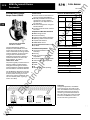
DeviceNet Starter Network
Adapter Product (DSNAP)
Table 33-20. IEC SNAP Connectivity
General Features
• Communication to DeviceNet con
suming one DeviceNet MAC ID
IEC E101, E501
m
• Advanced configuration using CH
Studio software
• Includes pre-wired starter interconnect cable
Comprehensive Motor Data and Control
• RMS average current
Size
45 mm
B
54 mm
76 mm
105 mm
• %thermal memory
• Integral contact position detection
an
• Operating status and fault codes
1 40 mm
• At speed (soft starters)
• START/STOP control
Catalog Number 0778-DSNAP
with 54 mm IT. Starter
Frame
Continuous
Ampacity
Rating
1 8 Amp
25 Amp
c
32 Amp
ua
ls
• Manually set MAC ID and baud rate;
configuration using a software
application is not required for nor
mal operation
40 Amp
50 Amp
D
65 Amp
85 Amp
1 00 Amp
E
1 25 Amp
1 60 Amp
200 Amp
F
250 Amp
3 1 5 Amp
400 Amp
•
Table 33-21. NEMA SNAP Connectivity
Extended Starter Capabilities
NEMA N101,N501
• Ground fault detection (with
accessory)
Size
Fault log
•
Start-up nuisance trip avoidance
(adjustable)
ar
•
• Current level warning (adjustable)
• Underload warning (adjustable)
Approvals
00
0
1
• CE
• CSAC22.2 No. 14-95 (pending)
9
18
27
45
4
1 35
3
90
270
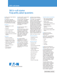
Table 33-22. S751 SNAP Connectivity
I S751 Soft Start
1 54 mm
1 27 Amps
w
.E
lec
tri
The IT. DSNAP is designed for use with
the same 24V DC power as the starter.
A starter power sensing circuit indi
cates to the user that the Starter does
not have 24V DC power, signaling a
fault or an E-Stop.
Continuous Ampacity
Rating
2
5
• UL508
ca
The product greatly increases the func
tionality of Eaton's Cutler-Hammer
Intelligent Technologies (IT.) Electro
mechanical Starter and S751 Soft Start
with the addition of enhanced features.
Trip Reset
lP
The DeviceNet Starter Network
Adapter Product (DSNAP) is a front
mount device that serves as a single
node on DeviceNet, providing commu
nication capability, control and moni
toring to Eaton's Cutler-Hammer
Intelligent Technologies (IT.) Electro
mechanical Starters, as well as the
S751 Soft Start. as listed in
Tables 33-20- 33-22.
tM
• RUN/FORWARD-REVERSE control
G
I
I
Application
In a typical application, the DSNAP
front mounts to an IT. starter or soft
start.The DSNAP connects directly to
DeviceNet, allowing for control and
monitoring of the starter/soft start. A
PC or PLC serves as the central control
and scans the DSNAP for motor con
trol and monitoring information.
IT. Combo
Starter with
Cover Control
Device Net
I
ww
Figure 33-4. Typical DSNAP Application
For more information contact Cutler-Hammer at:
www.cutler-hammer.eaton.com
CA0330500 1 E
NEMA Co�tactors & Starters
Accessones
March 2002
IT. Electro-Mechanical Line
Table 33-23. DeviceNet Specifications
DeviceNet Connections
Front
Group 2 Master Slave Connection Set
Polling
Bit Strobe
Explicit
NoUCMM
DeviceNet Baud Rate
r
[P
l
1 25K, 250K, 500K
2.4 r-(62)
Table 33-24. DSNAP Specifications
I Description
I Specifications
Transportation
Temperature
Humidity
Side
b
ua
ls
TBD
Module Current Draw
33-17
.c
om
Cutler-Hammer
1 .0 -1
�(26)
95% non-condensing
Storage
c
ED
b
h.-- 1 .3 ----I
(32)
Humidity
95% non-condensing
Table 33-25. Product Selection
I Description
Operating
Temperature
TBD
Altitude
Above 2000 meters (6600 feet) consult
factory
Humidity
15 g's ha lf-wave sinusoidal 1 1 msecs
Pollution Degree IEC60947-1
3
IP20
-
TBD
-
ww
w
.E
lec
tri
ca
lP
Enclosure
5 - 57.5 Hz ( 1 00 - 1 7 msecs) @
.3 mm SA
57.5 - 1 50 Hz ( 1 7 - 6.7 msecs) @
.35 mm SA
Auxi l i a ry Contact and Jumper
(for Full Voltage Reversing)
D77B-DSNAP
ar
Vibration
I Catalog Number I Price u.s. sl
Device Net Starter Network Adapter
Product and Prewired Starter
Interco nnect Cable
tM
95% non-condensing
Shock
an
Figure 33-5. DSNAP Approximate Dimensions in Inches (mm)
Temperature
CA03305001 E
Discount Symbol .
For more information contact Cutler-Hammer at:
www.cutler-hammer.eaton.com
. . . . . . . . . . . . . . . . . . . . . . . 1CD1
Cutler-Hammer
N EMA Co�tactors & Starters
Accessones
.c
om
33_18
March 2002
ll Electro-Mechanical Line
Table 33-26. IEC SNAP Connectivity
General Features
GCPort Starter Network Adapter
Product (GSNAP)
• Communication to QCPort consum
ing a single QCPort ID
IEC E101, E501
m
• Advanced configuration using CH
Studio software
• Includes pre-wired starter
interconnect cable
Comprehensive Motor Data and Control
• RMS average current
• Integral contact position detection
• At speed (soft starters)
• START/STOP control
tM
• Trip Reset
54 mm
1 8 Am p
25 Amp
c
76 mm
32 Amp
1 40 mm
40 Amp
50 Amp
65 Amp
D
85 Amp
100 Amp
1 25 Amp
E
1 60 Amp
200 Amp
250 Amp
F
315 Amp
400 Amp
NEMA N101, N501
• Ground fault detection (with
accessory)
Size
• Fault log
00
ar
• Current level warnings (adjustable)
• Underload warnings (adjustable)
lP
Approvals
• CE
ca
• CSAC22.2 No. 14-95 (pending)
lec
tri
The IT. QSNAP is designed for use
with the same 24V DC power as the
starter. A starter power sensing circuit
indicates to the user that the Starter
does not have 24V DC power, signaling
a fault or an E-Stop.
with
OS NAPs
I\: C!l (!)
r-r\l 0
I
r-
�
,.
! �
...\l.,.....
]o
i r- 1
0 r-
�
,------
�r-Io
r
1
I
r-
�
Continuous Ampacity
Rating
9
18
27
2
45
4
135
3
90
270
Table 33-28. S751 SNAP Connectivity
I S751 Soft Start
1 54 mm
10 �
IT. Starters
0
5
• UL508
IO ��G�eway
Table 33-27. NEMA SNAP Connectivity
Extended Starter Capabi lities
• Start-up nuisance trip avoidance
(adjustable)
The product greatly increases the func
tionality of Eaton's Cutler-Hammer
Intelligent Technologies ( IT.) Electro
mechanical Starter and S751 Soft Start
with the addition of enhanced features.
.E
B
Continuous
Ampacity
Rating
• RUN/FORWARD-REVERSE control
The QCPort Starter Network Adapter
Product (CSNAP) is a front-mount
device that serves as a single QCPort
device, providing communication
capability, control and monitoring to
Eaton's Cutler-Hammer Intelligent
Technologies ( IT.) Electromechanical
Starters, as well as the S751 Soft Start,
as listed Tables 33-26 - 33-28.
���
��n
45 mm
an
• Operating status and fault codes
PC or
PLC
Size
1 05 mm
• %thermal memory
Catalog Number 0778-QSNAP
with 54 mm IT. Starter
Frame
ua
ls
• Manually set Group ID;
configuration using a software
application is not required for
normal operation
1 27 Amps
Application
System
Power
Supply
,---
l li"ll
�
In a typical ap plication, the QSNAP
front mounts to an IT. starter or soft
start. The QSNAP connects direct l y
t o QCPort, allowing for control and
monitoring of the starter/soft start. A
PC or PLC serves as the central
control, and scans the DeviceNet
Adapter (D77D-DNA), retrieving the
QSNAP's motor control and
monitoring information.
ww
w
F1gure 33-6. Typical OSNAP Application
For more information contact Cutler-Hammer at:
www.cutler-hammer.eaton.com
CA0330500 1 E
NEMA Contactors & Starters
_
Accessones
March 2002
IT. Electro-Mechanical Line
Table 33-29. QSNAP Specifications
I Specifications
I Description
Front
Side
Transportation
Temperature
J
95% non-condensing
H u m idity
Storage
Temperature
-581 to 1 76YF (-50Yto 80YC)
ua
ls
95% non-condensing
H u m idity
Operating
Temperature
TBD
Altitude
Above 2000 meters (6600 feet) consult
factory
95% non-condensing
H u midity
1-
5 - 57.5 Hz ( 1 00 - 1 7 msecs) @ 0.3 mm SA
57.5 - 1 50 Hz ( 1 7 - 6.7 msecs) @ 0.35 mm
SA
3
I
1 .0
-1
(26)
Table 33-30. Product Selection
I Description
IP20
I
1---
J
I
1 .3
--------1
(32)
Figure 33-7. QSNAP Approximate Dimensions in Inches (mm)
an
Pollution Degree IEC60947-1
Enclosure
I
15 g's half-wave sinusoidal 1 1 msecs
Shock
Vibration
33_19
.c
om
Cutler-Hammer
tM
QCPort Starter Network Adapter Product
and Prewired Starter I nterconnect Cable
D77B-OSNAP
-
TBD
-
ww
w
.E
lec
tri
ca
lP
ar
Auxiliary Contact and J u m per (for Full
Voltage Reversi n g )
I Catalog Number I Price u.s. sl
CA03305001 E
Discount Symbol . .
For more information contact Cutler-Hammer at: www.cutler-hammer.eaton.com
. . . . . . . . . . . . . .
.
. . . . . .
. 1 CD1
Cutler-Hammer
.c
om
NEMA Contactors & Starters
Renewal Parts
33_20
March 2002
IT. Electro-Mechanical Line
Contact Kits
Din Rail Catch
lugs
\I/
Ill
Table 33-34. Lug Kits
Table 33-33. DIN Rail Catch
NEMA
Size
Description
Catalog
Number
00 - 1
Catch with Leaf
Spring & Pad
EMDRCB
EMDRCD
Table 33-31. Contact Kits
40 Amp
50 Amp
1
1
2
2
2
3, 4
3, 4
3, 4
5
5
5
65 Amp
85 Amp
1 00 Amp
1 25 Amp
1 60 Amp
200 Amp
250 Amp
3 1 5 Amp
400 Amp
Catalog
Number
-
Bus Bars
-
EMCKT125
EMCKT160
EMCKT200
-
EMCKT250
EMCKT315
EMCKT400
3, 4
5
5
5
-
EMCKT65
EMCKT85
EMCKT100
-
5
Price
U.S.$
EMCKT40
EMCKT50
1
2
Description
Catalog
Number
Lug
EMLUGC
-
EMLUGD
-
Lug
Lug
Horizontal Box
Lug Kit
Vertical Box
Lug Kit
Dual Lug Kit
Ring Lug Kit
Price
U.S.$
EM LUGE
-
EM LUG FA
-
EMLUGFB
-
EMLUGFC
EMLUGFD
-
tM
Contact Kit
Description
-
NEMA
Size
ar
NEMA
Size
Price
U.S.$
an
Catch with Leaf
Spring & Pad
2
ua
ls
m
Ill
-
ca
lP
Coils
Table 33-35. Bus Bars
NEMA
Size
Description
Catalog
Number
00, 0
For Contactors & Starters
EMBBB
Table 33-32. Coils
CD
Size 1 Coil
Size 2 Coil
Size 3, 4 Coil
EMCC
-
EMCD
-
EMCE
-
EMCF
-
3, 4
3, 4
5
For Starters
For Reversing Contactors &
Reversing Starters
For Starters
For Reversing Contactors &
Reversing Starters
Overload Relay
-
EMBBC
EMBBRC
-
EMBBD
EMBBRD
-
EMBBE
EMBBRE
-
EMBBOF
-
For reversi n g contactors and starters, order
two.
ww
w
CD
2
2
Price
U.S.$
For Starters
For Reversing Contactors &
Reversing Starters
.E
Size 5 Coil
Catalog
Number
lec
Description
tri
1
1
Price
U.S.$
Discount Symbol . . .
For more information contact Cutler-Hammer at: www.cutler-hammer.eaton.com
. . . . . . . .
..
. .
..
. . . . . . .
1 CD1
CA03305001 E
NEMA Contactors & Starters
Renewal Parts
March 2002
IT. Electro-Mechanical line
ua
ls
Connectors
Table 33-36. Control Terminal Connectors
Terminals
4
5
-+pF
8
8
8
8
(1)
(1)
(2)
(2)
(1)
(1)
(1)
(1)
5
5
5
5
8
5
8
5
(1) 8
(2) 5
(1) 5
CD
5
5
5
5
5
5
5
5
5
5
5
5
5
5
5
-+PF
-+PF
-+PF
-+PF
R
R
R
R
-+PFR
RFP+-+PFR
RFP+-
1
1
1
1
2
2
2
2
3
3
3
3
-+PF R 1 23
RFP+-+PF R 1 23
R FP+-
-+PF R 1 23
RF P+-+PF R
Description
Size
Size 00 - 1 Coil Controller
00 - 1
Size 2 - 4 Coil Controller
Reversing Coil Controller
Overload (except Size 5)
Reversing Overload (Size 5)
Size 5 Contactor
Size 5 Contactor
Size 5 Reversing Contactor
Size 5 Reversing Contactor
Size 5 Overload
Size 5 Overload
Size 5 Reversing Overload
Size 5 Reversing Overload
Size 5 Reversing Overload
Size 5 Reversing Overload
Size 5 Reversing Overload
00 - 5
00 - 5
00 - 4
00 - 4
5
5
5
5
5
5
5
5
Used With ®
Catalog
Number CD
- 02N - XCXNN
EMA78L
02N - XCXNN
- 03N - XCXNN
- 05N - XR - 3A
- 06N - XR - 3A
EMA76L
EMA76L
EMA76L
EMA76L
-
an
Pitch
(mm)
- 111F - X3N
- 111F - X3N
- 511F - X3N
- 511F - X3N
tM
No. of
Pins
5
5
5
EMA76L
lP
00, 0
00, 0
For Starters
For Reversing Contactors
EMOCSB
EMCCCB
1
1
2
2
For Starters
For Contactors
For Starters
For Contactors
.E
3, 4
3, 4
For Starters
For Reversing Contactors
For Starters
For Contactors
-
EMOCSD
EMCCCD
-
EMOCSE
EMCCCE
-
EMOCSF
EMCCCF
I
-
-
ww
w
5
5
EMOCSC
EMCCCC
Price
U.S.$
CA0330500 1 E
For more information contact Cutler-Hammer at:
www.cutler-hammer.eaton.com
Price
U.S.$
-
-
- 501F - - - 3A
- 501F - - - 3A
- 501F - - - 3A
ca
tri
Catalog
Number
lec
Description
m
-
EMA77L
EMA76L
Table 33-37. Overload and Coil Controller Covers
NEMA
Size
EMA77L
- 05NFXR - 3A
- 05NFXR - 3A
- 05NFXR 3A
- 05NFXR _ 3A
ar
Suffix L i n dicates locking.
® _ i ndicates missing digit of the Catalog N u m ber; may have m u ltiple values.
Overload and Coil Controller Covers
33-21
.c
om
Cutler-Hammer
-
EMA76L
-
EMA77L
-
N�MA �ontactors & Starters
D1mens1ons
Cutler-Hammer
.c
om
33_22
March 2002
IT. Electro-Mechanical Lin e
Non-reversing Contactors ( Sizes 00 - 1 )
Table 33-38. Approximate Dimensions in Inches (mm)
Depth w/
Auxiliary
Depth
added w/
DIN Rail
Width
Height
Mtg.
Hole to
Top
DIN Rail
to Top
A
B
c
D
E
F
G
H
J
K
1 .8
(45)
4.4
(111)
2.4
(60)
3.6
(91 )
.1
(3)
1 .33
(33.8)
4.0
(101)
.2
(5)
.9
(23)
(3) #8
M4
2.1
(54)
4.45
(1 13)
2.4
(60)
.1
(3)
3.6
(9 1 )
---t::=:"i •1
Li ne Termina l s
( 1 L 1 , 3 L 2 , 5 L3)
c
D
1 .46
(37)
"I
0
Standard
DIN Rail
1 .38 X .3
(35 X 7.5)
(Optional M o u nting) 1'----'-r-;-::-"--'
Control
line
load
p
a
R
.7
(19)
1.2
(30)
1 .2
(30)
.8
(20)
(3) #8
M4
.7
(19)
1 .2
(30)
1 .2
(30)
� Dual Auxi l i ary Reduce D i m " D "
/
0
.31 (8) for the
Single Auxiliaries
� Load Terminals
ar
(2 T 1 , 4 T2, 6 T3)
'+--- Control
Terminal Block
w
.E
lec
tri
ca
Figure 33-8. Approximate Dimensions - Inches (mm)
lP
E
.2
(5)
4.1
( 1 04)
Terminals
ua
ls
1
Depth
an
00, 0
Req. Mtg.
Screws
Height
ww
m
Mounting Holes
Overall
Width
tM
NEMA
Size
For more information contact Cutler-Hammer at:
www.cutler-hammer.eaton.com
CA03305001 E
N�MA �ontactors & Starters
D1mens1ons
33-23
.c
om
'
Cutler-Hammer
M a rch 2002
IT. Electro-Mechanical Line
Non-reversing Contactors (Sizes 2 - 4) C'J
Table 33-39. Approximate Dimensions in Inches (mm)
Depth
Depth w/
Auxiliary
Depth
added w/
DIN Rail
Width
Height
Mtg.
Hole to
Top
DIN Rail
to Top
A
B
c
D
E
F
G
H
J
3.0
(76)
5.9
( 1 50)
3.1
(79)
4.2
( 1 07)
.2
(4)
.94
(24)
2.87
(73)
.5
(13)
4.1
( 1 05)
8.0
(203)
(i) Sizes 5, consult factory.
3.5
(90)
4.7
( 1 1 9)
-�-0�
Line Terminals
(1 L 1 . 3 L2, 5 L3)
1 .33
(33.8)
-
1
D
�
n �I
0
Standard
DIN Ra i l
1 .38 X .3
(35 X 7.5)
(Opti o n a l Mounting)
.6
( 1 5)
Terminals
Control
Line
Load
K
p
a
R
.9
(23)
1.5
(37)
.6
( 1 4)
-
(4) #6 X 2
M3.5 x 50
(4) #8 X 1 .5
M4 x 40
1 .7
(42)
Dual Auxi l i a ry
Reduce D i m " D "
. 3 1 ( 8 ) f o r the
Single Auxi l i a ries
B G
lP
ca
w
.E
lec
tri
Figure 33-9. Approximate Dimensions - Inches (mm)
ww
2.8
(72)
H
'+--+-- Load Terminals
(2 T 1 , 4 T2, 6 T3)
CA03305001 E
2.4
(60)
•
ar
0
4.13
( 1 05)
Req. Mtg.
Screws
ua
ls
3, 4
Height
an
2
Mounting Holes
Overall
Width
tM
NEMA
Size
For more information contact Cutler-Hammer at:
www.cutler-hammer.eaton.com
'--=t--- K
(Sizes
2, 3 and 4)
.3
(8)
m
N�MA � ontactors & Starters
D1mens1ons
Cutler-Hammer
.c
om
33_24
March 2002
ll Electro-Mechanical line
Reversing Contactors (Sizes 00 - 4) CD
Table 33-40. Approximate Dimensions in Inches (mm)
2
3, 4
Depth w/
Auxiliary
A
B
c
D
3.8
(96)
5.9
( 1 49)
2.7
(69)
3.8
(96)
4.5
( 1 1 4)
6.2
( 1 58)
8.5
( 2 1 6)
2.6
(67)
5.9
( 1 49)
4.9
( 1 25)
G:l S1ze 5, consult factory.
�Q�
Line Terminals
(1 L 1 , 3 L2, 5 L3)
I
Height
Mtg.
Hole to
Top
DIN Rail
to Top
E
F
G
H
J
3.15
(80)
5.35
( 1 36)
.3
(7)
3. 1 5
(80)
-
4.4
( 1 1 2)
3.8
(97)
9.5
(242)
Width
-
3.8
(96)
3.3
(84)
7.4
( 1 88)
Depth
added w/
DIN Rail
5.51
( 1 40)
-
7.87
(200)
-
5.35
( 1 36)
6 .89
( 1 75)
9.06
(230)
.3
(7)
.2
(6)
.2
(6)
Req. Mtg.
Screws
K
(3) # 1 0
M5
-
-
Reduce D i m " D "
.31 (8) f o r the
S i ngle Auxiliaries
ca
lP
0
a
R
-
(3) # 1 0
M5
3.1
(80)
2.1
(54)
.7
(17)
i!S
0
lEIJ
�
K
nell
e Qs
,J
@@@@@
L
1:::1
r.:!l.
'>U
�Lt:t
.9
(22)
@�@ @
@
0
@@@@@
1 .9
(48)
2.6
(67)
QQg
0
.9
(22)
.6
( 1 6)
(3) # 1 0
M5
-
1 .5
(38)
1..1!::1
CP
J!t
tri
Control
Terminal Block
p
1.5
(38)
@ � @ ®@
B G
Load
2.0
(50)
nell
� ual Aux i l i a ry -
Line
2.0
(50)
H
0
Control
(3) # 1 0
M5
•
D
Terminals
ua
ls
1
Depth
an
00, 0
Mounting Holes
Height
tM
El
Overall
Width
ar
NEMA
Size
ww
w
.E
lec
Figure 33-10. Approximate Dimensions - Inches (mm)
For more information contact Cutler-Hammer at:
www.cutler-hammer.eaton.com
CA03305001 E
N�MA � ontactors & Starters
D1mens1ons
March 2002
33-25
IT. Electro-Mechanical Line
Non-reversing Starters ( Sizes 00 - 4) CD
Table 33-41. Approximate Dimensions in Inches (mm)
NEMA Overall
Size
Width Height
Height
Mtg.
Hole
to Top
DIN Rail
to Top
Req. Mtg.
Screws
Height
Depth
Control
Line
Load
N
p
a
R
2.5
(63)
(44)
1 .7
1 .2
(30)
.6
( 1 6)
c
D
E
F
G
H
J
K
L
M
1 .8
(45)
5.0
( 1 27)
2.5
(63)
3.6
(9 1 )
.1
(3)
1 .33
(33.8)
4.62
( 1 17.3)
.2
(5)
.9
(23)
(3) #8
M4
.6
( 1 4)
3.6
(91 )
3.0
(76)
5.9
( 1 50)
.94
(24)
2.87
(73)
4.1
( 1 05)
8.0
(203)
G) Size 5 , consult factory.
2.5
(63)
3.6
(91 )
3.5
(90)
4.7
( 1 19)
3. 1
(79)
4.2
( 1 07)
.1
(3)
.2
(4)
-
--t--01
Line Terminals
(1 L 1 , 3 L2. 5 L3)
1 .46
(37)
D
1
1 .33
(33.8)
5.04
( 1 28)
.2
(5)
4.13
( 1 05)
.6
( 1 5)
�
n �I
0
Standard
DIN Ra i l
1 .38 X .3
(35 X 7.5)
(Optional M o u nting)
0
El
.9
(23)
.5
( 1 3)
-
(3) #8
M4
(4) #6 X 2
M3.5 x 50
(4) #8 x 1 .5
M4 x 40
.7
(17)
.7
(17)
.7
(17)
3.7
(93)
4.2
( 1 06)
5.7
( 1 46)
•
H
D u a l Auxi l i a ry
Reduce D i m " D "
.3 (7) f o r the
Single Auxi l i aries
B G
"--- Reset Button
lP
r=l===��
.8
(20)
ua
ls
B
5.4
( 1 38)
. 0 1 5 (0.4)
Deflection to Reset
"+---fl-- Load Terminals
tri
ca
(2 T 1 , 4 T2, 6 T3)
ww
w
.E
lec
Figure 33-11. Approximate Dimensions - Inches (mm)
CA03305001 E
For more information contact Cutler-Hammer at:
Terminals
Reset Button
Width
an
3, 4
Width
tM
2
Depth
added w/
DIN Rail
A
2.1
(54)
1
Depth w/
Auxiliary
ar
00, 0
Mounting Holes
Depth
.c
om
Cutler-Hammer
www.cutler-hammer.eaton.com
2.4
(62)
3.1
(78)
3.5
(88)
1 .8
(45)
1 .2
(30)
2.8
(72)
1 .7
(42)
2. 4
(60)
1.5
(37)
.3
(8)
.6
( 1 4)
.3
(8)
m
N�MA �ontactors & Starters
D1mens1ons
Cutler-Hammer
.c
om
33_26
March 2002
ll Electro-Mechanical Line
Reversing Starters (Sizes 00 - 4)CD
Table 33-42. Approximate Dimensions in Inches (mm)
B
c
D
3.8
(96)
5.9
( 1 49)
2.7
(69)
3.8
(96)
6.2
( 1 58)
7.4
( 1 88)
3.3
(84)
4.4
(112)
4.5
( 1 1 4)
1
2
3, 4
CD
A
8.5
( 2 1 6)
5.9
( 1 49)
2.6
(67)
9.5
(242)
3.8
(97)
Size 5, consult factory.
4.9
( 1 25)
+=01
Width
Height
Mtg.
Hole
to Top
E
F
G
H
5.35
( 1 36)
.28
(7)
6.89
( 1 75)
.24
(6)
-
3.8
(96)
Line Terminals
(1 L 1, 3 L2, 5 L3)
Depth
added w/
DIN Rail
3.15
(80)
3.15
(80)
5.35
( 1 36)
7.87
(200)
9.06
(230)
5.51
( 1 40)
.28
(7)
.24
(6)
DIN Rail
to Top
J
-
Reset Button
Width
Height
K
L
M
(3) # 1 0
M5
1 .6
(40)
2.3
(58)
(3) # 1 0
M5
1 .7
(43)
(3) # 1 0
M5
2.9
(73)
(3) # 1 0
M5
•
D
H
I
Depth
Control
Line
Load
N
p
a
R
3.8
(97)
2.7
(68)
2.0
(50)
1 .5
(38)
.9
(22)
5.5
( 1 39)
3.3
(83)
2.6
(67)
1 .9
(48)
.9
(22)
2.6
(65)
4.1
( 1 04)
7.2
( 182)
tt\
JO
T
�
I
_p_j
EN---c---�-->-1 1
ar
lP
0
B G
g�Q
ca
tri
Control
Terminal Block
0
0
0
@@@@@
lEll
IF===�===� ' Reset
Button
. 0 1 5 (0.4)
Deflection to Reset
2.1
(54)
3.1
(80)
.6
( 1 6)
.7
(17)
K
fl§ll
@ � @ @ I' @ � @ @
@
@
� ual Aux i l iary
Reduce D i m " D "
.3 (7) for the
Single Auxiliaries
1 .5
(38)
2.0
(50)
3.7
(94)
I �
fl§ll
0
Load Terminals
(2 T 1 , 4 T2, 6 T3)
Terminals
Req. Mtg.
Screws
ua
ls
00, 0
Depth w/
Auxiliary
tM
El
Mounting Holes
Depth
an
NEMA Overall
Size
Width Length
'
I'
e c�
.I
I'
@@@@@
Cl
' ""E'lJ
I'
l.
I�
�
'---�
-
�lE"
�
M
'- R eset
Bu tton
..t:l
1. 1-:�
L
ww
w
.E
lec
Figure 33-12. Approximate Dimensions - Inches (mm)
For more information contact Cutler-Hammer at:
www.cutler-hammer.eaton.com
CA03305001 E
NEMA Contactors & Starters
ww
w
.E
lec
tri
ca
lP
ar
tM
an
ua
ls
Ma rch 2002
CA03305001 E
For more information contact Cutler-Hammer at:
www.cutler-hammer.eaton.com
33-27
.c
om
Cutler-Hammer
m
.c
om
ua
ls
an
tM
ar
lP
ca
tri
lec
.E
Eaton Corporation
Cutler-Hammer business unit
1 000 Cherrington Parkway
Moon Township, PA 1 5 1 08-43 1 2
USA
tel: 1 -800-525-2000
ww
w
www.cutler-ham mer.eaton.com
© 2002 Eaton Corporation
Cutler- Hammer
All Ri ghts Reserved
Printed i n USA
Publication No. CA03305001E
March 2002