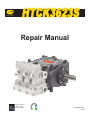
1
HTCK3623S
Repair Manual
General Pump is a
member of the
Interpump Group
8
Ref 300935 Rev.A
09-13
GENERAL PUMP
INDEX
1.
A member of the Interpump Group
HTCK3623S
INTRODUCTION . . . . . . . . . . . . . . . . . . . . . . . . . . . . . . . . . . . . . . . . . . . . . . . . . .Page 3
2.
REPAIR GUIDELINES . . . . . . . . . . . . . . . . . . . . . . . . . . . . . . . . . . . . . . . . . . . . . .Page
2.1 Repairing Mechanical Parts . . . . . . . . . . . . . . . . . . . . . . . . . . . . . . . . . . . . . . .Page
2.1.1 Disassembly of Mechanical Parts . . . . . . . . . . . . . . . . . . . . . . . . . . . .Page
-Remove the piston guide seal rings as described below: . . . . . .Page
2.1.2 Reassembly of Mechanical Parts . . . . . . . . . . . . . . . . . . . . . . . . . . . .Page
2.1.3 Reduction Classes . . . . . . . . . . . . . . . . . . . . . . . . . . . . . . . . . . . . . . .Page
2.1.4 Disassembly/Reassembly of Bearings and Shims . . . . . . . . . . . . . . .Page
2.2 Repairing Hydraulic Parts . . . . . . . . . . . . . . . . . . . . . . . . . . . . . . . . . . . . . . . . .Page
2.2.1 Dismantling the Head-Valve Units . . . . . . . . . . . . . . . . . . . . . . . . . . .Page
2.2.2 Reassembling the Head-Valve Units . . . . . . . . . . . . . . . . . . . . . . . . .Page
2.2.3 Dismantling the Head-Seals . . . . . . . . . . . . . . . . . . . . . . . . . . . . . . . .Page
2.2.4 Dismantling the Piston Unit . . . . . . . . . . . . . . . . . . . . . . . . . . . . . . . . .Page
2.2.5 Reassembling the Head-Seals-Piston Unit . . . . . . . . . . . . . . . . . . . . .Page
3.
SCREW CALIBRATION . . . . . . . . . . . . . . . . . . . . . . . . . . . . . . . . . . . . . . . . . . . . .Page 16
4.
5.
6.
3
3
4
5
6
8
8
11
11
12
13
15
15
REPLACING THE CONNECTING ROD FOOT BUSHING . . . . . . . . . . . . . . . . . .Page 17
REPAIR TOOLS . . . . . . . . . . . . . . . . . . . . . . . . . . . . . . . . . . . . . . . . . . . . . . . . . . .Page 18
MAINTENANCE LOG . . . . . . . . . . . . . . . . . . . . . . . . . . . . . . . . . . . . . . . . . . . . . .Page 19
Ref 300935 Rev.A
09-13
Page 2
GENERAL PUMP
A member of the Interpump Group
1. INTRODUCTION
HTCK3623S
This manual describes the instructions for repair of the HTCK3623S, and must be carefully read and
understood before performing any repair intervention on the pump. Proper pump operation and longevity
depend on the correct use and maintenance. General Pump declines any responsibility for
damage caused by negligence or failure to observe the instructions described in this manual.
2. REPAIR INSTRUCTIONS
2.1 Repairing Mechanical Parts
Mechanical parts repair must be performed after the oil has been removed from the casing. To drain
the oil, remove the oil dipstick, (1, fig. 1) and then the draining plug (2, fig. 1).
The oil must be placed in a suitable container and disposed of in special centers.
It absolutely must not be discarded into the environment.
Ref 300935 Rev.A
09-13
Page 3
GENERAL PUMP
A member of the Interpump Group
2.1.1 DISASSEMBLY OF MECHANICAL PARTS
HTCK3623S
The operations described must be performed after removing the hydraulic part, ceramic plungers and
splash guards from the pump (see 2.2.3 and 2.2.4).
Remove in the following order:
-the pump shaft tab
-the rear cover
-the connecting rod cap as follows:
unscrew the cap fixing screws, remove the connecting rod caps with their lower half-bearings
(fig. 2) paying attention to the numbered sequence during disassembly.
To avoid possible errors, caps and connecting rod shanks have been numbered on one side (fig. 2a, 1).
- the side covers using - for extraction - 3 fully threaded M6x50 screws,
inserting them in the threaded holes as indicated in fig. 3.
Ref 300935 Rev.A
09-13
Page 4
GENERAL PUMP
A member of the Interpump Group
HTCK3623S
-push the plunger guides forward with their con-rods to facilitate side extraction of the pump shaft
as shown in fig. 4
-Remove the pump shaft
-Complete disassembly of the con-rod units by removing them from the pump casing and removing
the plunger guide pins
-Remove the pump shaft seal rings using common tools
-Remove the plunger guide seal rings as described below:
Use the extractor, p/n 26019400 (fig. 5, 1) and the gripper p/n 27503900 (fig. 5, 2). Insert the gripper as far as
possible onto the seal ring with the aid of a hammer (fig. 5a), subsequently screwing the extractor to the gripper, and use the extractor hammer (fig. 5b) until the ring to be replaced is removed (fig. 5c).
Ref 300935 Rev.A
09-13
Page 5
GENERAL PUMP
A member of the Interpump Group
2.1.2 REASSEMBLY OF MECHANICAL PARTS
HTCK3623S
After having checked that the casing is clean, proceed with assembly of the mechanical part as described
below:
- Assemble the upper and lower half-bearings in their seats in the con-rods and caps.
Make sure that the reference marks on the upper half-bearings (fig.6, 1) and lower halfbearings (fig. 6a, 2) are positioned in their respective seats in the con-rod and cap.
-Insert the piston/con-rod guide units into the pump casing, directing the numbering on the con-rod
shank towards the top of the casing, taking care not to damage the piston guide seal rings.
To facilitate pump shaft insertion (without the tab), it is essential to repeat the operation performed during
disassembly, pushing the piston/con-rod guide units as far down as possible (paragraph 2.2.1).
-Before assembling the side cover on the PTO side, check the conditions of the radial ring lip seal and
relative contact area on the shaft.
If replacement is necessary, position the new ring using a tool p/n 27904500) as indicated in fig. 7.
If the pump shaft shows diametrical wear in the area of contact with the lip seal, in order to
prevent the grinding operation, it is possible to reposition the ring in abutment with the cover
as shown in fig. 7.
Before assembling the side covers, make sure there are O-rings on both of them and shim rings on the indicator side cover only. To facilitate filling of the first section and relative insertion of the covers on the casing,
we recommend using three partially threaded M6x40 screws (fig. 8,1), then completing the operation with the
screws supplied (M6x18).
Ref 300935 Rev.A
09-13
Page 6
GENERAL PUMP
A member of the Interpump Group
HTCK3623S
-Couple the con-rod caps to their shanks, referring to the numbering (fig. 9, 1).
Note the correct assembly direction of the caps.
Fasten the caps to their respective con-rod shanks by means of M8x1x42 screws (fig. 10) lubricating both
the underhead and the threaded shank. Proceeding in two different stages.
1. Manually turn the screws until they begin to tighten
2. Tighten torque: 22 ft.lbs. (30 Nm)
Alternately, ensure:
1. Pre-tightening torque: 7-11 ft.lbs. (10-15 Nm)
2. Tightening torque: 22 ft.lbs. (30 Nm)
-After having completing tightening operations, check that the con-rod head has a side clearance in
both directions.
-Insert the new plunger guide seal rings as far as possible into the relative seat on the pump casing
(fig. 11), following the procedure described:
Using tool p/n 27904200 composed of a tapered bushing and a buffer. Screw the tapered bushing into the
hole in the plunger guide (fig. 11a). Insert the new seal ring on the buffer as far as it will go (determined by
the height of the buffer) into its seat on the pump casing (fig. 11b), remove the tapered bushing (fig. 11c).
Ref 300935 Rev.A
09-13
Page 7
GENERAL PUMP
A member of the Interpump Group
HTCK3623S
- Mount the rear cover complete with the O-ring, positioning the dipstick hole upward.
- Insert oil in the casing as indicated on the specification sheet.
2.1.3 REDUCTION CLASSES
TABLE OF REDUCTIONS FOR CRANKSHAFTS AND CON-ROD HALF-BEARINGS
Recovery Classes
(mm)
0.25
0.50
P/N
Half-bearing
Upper
90922100
90922200
P/N
Half-bearing
Lower
90922400
90922600
Correction on the shaft
pin diameter
(mm)
Ø39.75 0/-0.02 Ra 0.4 Rt 3.5
Ø39.50 0/-0.02 Ra 0.4 Rt 3.5
2.1.4 DISASSEMBLY/REASSEMBLY OF BEARINGS AND SHIMS
The type of bearings (taper roller) ensures the absence of axial clearance on the crankshaft. The shims are
defined to meet this necessity. For disassembly/reassembly and for any replacements, carefully observe
the following directions:
Ref 300935 Rev.A
09-13
Page 8
GENERAL PUMP
A member of the Interpump Group
HTCK3623S
A) Disassembly/Reassembly of the crankshaft without bearings replacement.
After having removed the side covers as indicated in point 2.1.1, check the conditions of the rollers and their
relative tracks. If all parts are in good condition, clean the components carefully with a degreaser and
redistribute lubricant oil uniformly.
The previous shims can be reused, taking care to insert them only under the indicator side cover.
Once the complete unit (indicator side flange + shaft + motor side flange)is assembled and the cover screws
have been tightened to the recommended torque, check that the rotation torque of the con-rod shaft - with
the con-rod disconnected - is a minimum of 3 ft.lbs. (4 Nm) and a max. of 4.4 ft. lbs.(4-6 Nm).
To bring the two side covers closer to the casing, it is possible to use 3 M6x40 screws for the first
positioning phase as indicated in fig. 6 and the screws provided for final fastening.
Shaft rotation torque (with the con-rod connected should not exceed 6 ft.lbs. (8 Nm),
B) Disassembly/Reassembly of the crankshaft with bearings replacement.
After having removed the side covers as indicated in point 2.2.2, remove the outer ring nut of the bearings
from the relative covers and the inner ring nut with the remaining part of the bearing from the two ends of the
shaft by means of a normal “pin punch” or a similar tool as indicated in figs. 8 and 9.
The new bearings can be mounted cold with a press or rocker, supporting it on the lateral surface of the ring
nuts involved in press fitting with the rings. The press fitting operation can be facilitated by heating the
involved parts to a temperature between 250o-300o F (120o-150o C), ensuring that the ring nuts fit fully into
their seats.
Never exchange the parts in the two bearings.
Ref 300935 Rev.A
09-13
Page 9
GENERAL PUMP
A member of the Interpump Group
HTCK3623S
C) Determining the shim pack:
Perform the operation while the piston/con-rod units are assembled, the con-rod caps are disconnected and
the con-rods are pushed downwards. Insert the pump shaft without tab into the casing, making sure the PTO
shank comes out of the correct side.
Secure the PTO side flange to the casing, taking care with the lip seal as described previously and tighten
the fixing screws to the recommended torque.
Then feed the flange on the indicator side without shims in the cover and start to move it closer, manually
screwing the M4x40 service screws in equally, with small rotations such at to move the cover in slowly and
correctly.
At the same time, check that the shaft rotates freely by turning it manually.
Continuing the procedure in this way, a sudden increase in difficulty during shaft rotation will soon be
experienced.
At this point, halt the forward movement of the cover and loosen the fixing screws completely.
With the aid of a thickness gauge, measure the clearance between the side cover and pump casing (fig. 14).
Proceed to determine the shim pack, using the table below:
Detected
Measurement
From: 0.05 to 0.10
From: 0.11 to 0.20
From: 0.21 to 0.30
From: 0.31 to 0.35
From: 0.36 to 0.45
From: 0.46 to 0.55
From: 0.56 to 0.60
From 0.61 to 0.70
Shim
Type
/
0.1
0.1
0.25
0.35
0.35
0.10
.25
0.35
0.24
Number of
Pieces
/
1
2
1
1
1
1
2
1
1
Once the type and number of shims have been determined using the table, check the following:
assemble the shim pack on the indicator side cover centering (fig. 15). Secure the cover to the casing,
following the procedure in part 2.1.2 and tighten the screws to their recommended torque.
Check that the shaft rotation stall torque is between 3-4.3 ft.lbs.(4-6 Nm).
If this torque is correct, connect the con-rods to the crankshaft and to the next stages. If it is not, redefine the
shim pack, repeating the operations.
Ref 300935 Rev.A
09-13
Page 10
GENERAL PUMP
A member of the Interpump Group
2.2 REPAIRING HYDRAULIC PARTS
2.2.1 DISMANTLING THE HEAD - VALVE UNITS
HTCK3623S
Operations are limited to inspection or replacement of vavles, if necessary.
Proceed as follows to extract valve groups:
-Unscrew the 7 M12x35 valve cover fixing screws and remove covers (fig. 16, 16a).
-Extract valve plugs by means of an extractor hammer or an M6 threaded car (fig. 16)
-Extract valve units using a gripper (fig. 16a).
If the suction and outlet valves remain stuck on the head (for example because of incrustations
due to prolonged lack of use of the pump), proceed as follows:
-using extractor tool p/n 26019400 combined with tool p/n 27513700 (fig. 16b).
Ref 300935 Rev.A
09-13
Page 11
GENERAL PUMP
A member of the Interpump Group
HTCK3623S
- To dismantle the suction-outlet valves, simply use a tool as indicated in fig. 14
2.2.2 REASSEMBLING THE HEAD - VALVE UNITS
Pay particular attention to the conditions of the various components and replace if necessary, and at
intervals indicated in the ‘PREVENTIVE MAINTENANCE” on the specification sheet.
At every valve inspection, replace all O-rings and all anti-extrusion rings both in the valve
groups and on the valve plugs.
Before repositioning the valve unit, thoroughly clean and dry the relative seats in the head as shown
in fig. 18.
Ref 300935 Rev.A
09-13
Page 12
GENERAL PUMP
A member of the Interpump Group
HTCK3623S
To reassemble the various components, follow the reverse operations listed above as described in point
2.2.1. To facilitate insertion of the valve guide in its housing, you can use a brush resting on the horizontal
guide planes and use a hammer acting on the whole circumference (figs. 19a).
Insert the suction and outlet valve units, checking that they are down to end stroke in the head
housing. Then apply the valve covers and calibrate the respective M12x25 screws using a
torque wrench at the required tightening torque.
2.2.3 DISMANTLING THE HEAD - SEALS
Replacement of the seals is necessary from the moment you begin to detect water leaks from the drainage
holes provided on the back of the pump casing, and at the intervals indicated in the “Preventive Maintenance”
section on the specification sheet.
A) Unscrew the M10x110 head fixing screws as indicated in fig. 20.
B) Separate the head from the pump casing
C) Extract the high pressure seals from the head and the low pressure ones from the support, using simple
tools as indicated in (fig. 21) being careful not to damage the respective housing.
Ref 300935 Rev.A
09-13
Page 13
GENERAL PUMP
A member of the Interpump Group
HTCK3623S
Pay attention to the order of seal pack disassembly as indicated in fig. 23 composed of:
1. High pressure seal ring
2. Intermediate ring
3. Low pressure seal ring
4. Bottom ring
5. O-ring
Ref 300935 Rev.A
09-13
Page 14
GENERAL PUMP
A member of the Interpump Group
2.2.4 DISMANTLING THE PISTON UNIT
HTCK3623S
The piston unit does not require any routine maintenance. Maintenance is limited to visual checks only.
Proceed as follows to remove the piston units:
A) Unscrew the piston fixing screws as indicated in fig. 23.
B) Check and verify their conditions, replace if necessary.
At every disassembly, all O-rings on the piston unit must be replaced.
2.2.5 REASSEMBLING THE HEAD - SEALS - PISTON UNIT
To reassemble the various components, follow the reverse operations listed above as described in point
2.2.3, taking particular care to the described instructions:
A) Seals pack: respect the same order used during disassembly operations.
B) Lubricate components 1 and 3 with OCILIS 250 silicone grease p/n 12001600; only on the external
diameter.
C) For correct assembly of HP seals in their housing on the head without causing any damage to lip seals,
use suitable tools according to the pump diameters as indicated in Chapter 5.
D) Replace the piston, tightening the screws with a torque wrench, respecting the tightening torque as
indicated in Chapter 3.
E) Assembling the head: for the values of the torques and tightening sequences follow the instructions in
Chapter 3.
Ref 300935 Rev.A
09-13
Page 15
GENERAL PUMP
A member of the Interpump Group
3. SCREW TIGHTENING CALIBRATION
Description
Cover fixing screw
Piston fixing screw
Connecting rod cap fixing screw
Head fixing screw
Valve cover fixing screws
Oil discharge plug
G1” outlet plug
G1-1/2” suction plug
Type “A” flange fixing screw
Exploded Drawing
Position #
9
28
16
39
40
11
31
29
66
* The connecting rod cap fixing screws must be tightened
respecting the stages indicated on page 7
HTCK3623S
Tightening Torque
7.4 ft.lbs. (10 Nm)
14.8 ft.lbs (20 Nm)
22.1 ft.lbs (30 Nm)*
29.5 ft.lbs (40 Nm)**
59.0 ft.lbs (80 Nm)***
29.5 ft.lbs (40 Nm)
73.8 ft.lbs (100 Nm)
88.5 ft.lbs (120 Nm)
16.2 ft.lbs (22 Nm)
** The head fixing screws must be tightened with a
torque wrench, lubricating the underhead, respecting the order in fig. 24
*** The valve cover fixing screws must be tightened with a torque wrench,
lubricating the underhead, respecting the order in fig. 24
Ref 300935 Rev.A
09-13
Page 16
GENERAL PUMP
A member of the Interpump Group
HTCK3623S
4. REPLACING THE CONNECTING ROD FOOT BUSHING
During maintenance, if it becomes necessary to replace the connecting rod foot bushing, proceed as follows:
When removing the worn bushing, take great care not to damage or scratch the seat on the
connecting rod.
Perform cold press fitting of the new bushing. During this operation, ensure that:
• the lubrication hole coincides with the corresponding hole on the connecting rod;
• the cutting junction is directed as shown in fig. 25
Then perform mechanical processing. The dimensions and tolerances shown in fig. 25 MUST be
respected.
Ref 300935 Rev.A
09-13
Page 17
GENERAL PUMP
4. REPAIR TOOLS
A member of the Interpump Group
HTCK3623S
Pump maintenance and repairs are facilitated by the use of special toos, listed in the table below:
For Assembly:
•
•
•
Seal bushing Ø 48; HP alternative seal ring Ø 36x48x8 . . . . . . . . . . . . . . 26406300
27465800
Buffer for pump shaft oil seal . . . . . . . . . . . . . . . . . . . . . . . . . . . . . . . . . . . 27904500
Buffer for piston guide oil seal . . . . . . . . . . . . . . . . . . . . . . . . . . . . . . . . . . 27904200
For Disassembly:
•
Suction/outlet valve seat . . . . . . . . . . . . . . . . . . . . . . . . . . . . . . . . . . . . . . . 26019400
27513700
•
Piston guide oil seal extraction gripper . . . . . . . . . . . . . . . . . . . . . . . . . . . . 26019400
27503800
Ref 300935 Rev.A
09-13
Page 18
GENERAL PUMP
A member of the Interpump Group
5. MAINTENANCE LOG
HTCK3623S
HOURS & DATE
OIL CHANGE
GREASE
PACKING
REPLACEMENT
PLUNGER
REPLACEMENT
VALVE
REPLACEMENT
GP Companies, Inc.
1174 Northland Drive
Mendota Heights, MN 55120
Phone:651.686.2199 Fax: 800.535.1745
www.generalpump.com email: [email protected]
Ref 300935 Rev.A
09-13
Page 19