1
OPC Server for Honeywell C-BUS – Quick Start
Revision 2.3
C-BUS OPC Server - Quick Start
The following sections describe how to use the supplied KZK OPC Server. The OPC
Server’s functionality can be divided into the configuration & installation part and the
on-line part described in the following sections.
Configuration of Hardware
The OPC Server requires the Intelligent External Converter (IEC) for the physical
connection to the C-BUS media layer. The IEC is a microprocessor-based single chip
device, and the manual configuration by jumpers and DIP switches is required only if
you install the Lantronix CoBox module for Ethernet connections between the
OPC Server and the IEC. All other configuration steps can be made by software tools
and utilities (e.g. changing a C-BUS address for the IEC or assigning an IP address to
the IEC with the installed Ethernet sub-module).
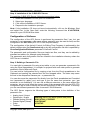
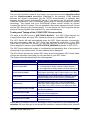
Step 1: IEC Connection and Mounting
To secure the connection of your
Intelligent External Converter (IEC),
follow the instructions below:
1. Connect the IEC to the C-BUS
(RS485) through a two-wire circuit.
Figure 1: Wiring diagram for IEC Converter
The LAN link indicator lights green to
indicate 10/100 Mbps Ethernet connection.
The LAN link indicator lights or blinks red
(except the start-up procedure) to indicate
error detection in the configuration of the
Ethernet sub-module.
Note: The IEC supports C-BUS speeds of
4.800, 9.600, 19.200, 38.400, 76.800 bps
and Ethernet speeds of 10/100 Mbps.
Step 2: Assigning an IP address to IEC
2. (If you have installed the Ethernet
sub-module, you can skip this step.)
Connect the IEC to the PC (Personal
Computer) through RS232 or RS485.
For long distance between the IEC
and PC you can use RS485 interface
but you have to use RS485 to RS232
converter with ADDC.
3. (If you have not installed the Ethernet
sub-module, you can skip this step.)
Connect the IEC to the network using
Hub or Switch through the Ethernet
port (The IEC must be on the same
network segment as your PC with the
installed C-BUS OPC Server).
4. Plug the IEC in the power supply
(24V DC or equivalent AC voltage).
The required input voltage is 10-25V.
Find Power Supply Wiring of IEC.
If you have not installed the Ethernet sub-module, please skip this step.
If you wish to install the Ethernet sub-module, please proceed to the additional section:
Installation of the Ethernet sub-module.
The IEC is shipped with the default IP address: 192.168.1.254
For changing the default IP address, use the UDSIP utility from the installation CD.
Click Run from the Windows Start menu and type the following command line
X:\LAN\LANTRONIX\UDSIP where X is your CD-ROM drive letter.
Copyright © 2012, KZK spol. s.r.o.
Page 1
OPC Server for Honeywell C-BUS – Quick Start
Revision 2.3
In order to successfully assign an IP address to the IEC using the UDSIP utility, you
must use the address that is on the same subnet as the computer that you are using. To
get the IP address of your computer, if you are using Microsoft Windows 9X, you can go
to an MS-DOS prompt and issue the command 'winipcfg'.
If you are using Microsoft Windows NT/2000/XP, use the command 'ipconfig'.
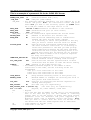
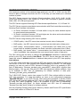
To assign a new IP address to your
IEC, follow the instructions below:
1. In the 'Enter IP Address to assign
field, type the IP address of the IEC
(XXX.XXX.XXX.XXX format).
In the 'Enter the Hardware Address'
field, type the Ethernet address (MAC
address) listed on the IEC label (on
the right side of the IEC).
2. Click on the 'Set IP Address'
button, and USDIP will attempt to
assign the new IP address.
Figure 2: The UDSIP utility dialog box
To check the assigned IP address to the IEC, use ping utility.
In the MS-DOS prompt, type the following command ‘ping XXX.XXX.XXX.XXX’, where
XXX.XXX.XXX.XXX is the IP address of IEC. The Reply received message indicates
that the new IP address has been assigned successfully.
Note: Before assigning an IP address to the IEC please check, using the ping utility,
whether this IP address has not been used by another device.
Step 3: Installation of COM Port Redirector
If you have not installed the Ethernet sub-module, please skip this step.
If you do not use IEC unit as RS-232/RS-485 to Ethernet converter (RS-232/RS-485
interface will be available as a virtual COM port), please skip this step.
Use the RED32BIT Windows 95/98/NT/2000/XP driver from the installation CD.
Click Run from the Windows Start menu and type the following command line:
X:\LAN\LANTRONIX\REDIRECTOR\RED32BIT where X is your CD-ROM drive letter.
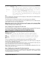
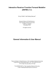
After the successful installation,
click on the Windows Start and
select Programs Lantronix
Redirector Configuration.
Tip: You can download the latest
version of Lantronix COM Port
Redirector from Lantronix’s web:
www.lantronix.com/support
Figure 3: The Redirector Configuration tools dialog box
Copyright © 2012, KZK spol. s.r.o.
Page 2
OPC Server for Honeywell C-BUS – Quick Start
Revision 2.3
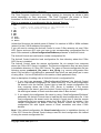
To create virtual COM ports for Ethernet connections between the OPC Server and the
IEC, follow the instructions below:
1. Click on the 'Com Setup' button and
select the redirected ports.
Tip: You can also use the TCP port
number 3002 for the second channel of
IEC and create a virtual COM port
associated with the RS-232 and RS-485
interface that is usually used for
connections between IEC and PC,
without using the Ethernet sub-module.
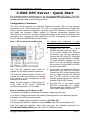
4. Click on the 'Port Settings' button
and set the reconnect parameters.
Figure 4: The Port Setup dialog box
2. Select Redirect COM port in the Port
Configuration group.
3. Click on the 'Add IP' button and add
the IP address of the IEC.
Figure 6: The Port Settings dialog box
The auto reconnects mechanism works
only if you check the Timeout
Reconnect and Server Reconnect
options.
You can also decrease the value of the
Connection Timeout (the number of
seconds before the re-establishment of
the failed connection is attempted).
5. Click on the 'Save' button and reboot
your PC.
Figure 5: The IP Service Setup dialog box
In the Host field, type the IP address of
the IEC. In the TCPPort field, type the
TCP port number 3001.
When the COM Port Redirector is
properly configured you can suppress
the status windows by checking the
Silent Mode parameter.
Note: Remember that if you change the
IP address of the IEC, you have to
reinstall the corresponding virtual COM
ports.
Note: You must have the TCP/IP protocol installed and configured before installing the
COM Port Redirector.
Copyright © 2012, KZK spol. s.r.o.
Page 3
OPC Server for Honeywell C-BUS – Quick Start
Revision 2.3
Step 4: Installation of the C-BUS OPC Server
To install the C-BUS OPC Server, follow the instructions below:
1.
2.
3.
4.
Insert the installation CD into your CD-ROM drive.
Select your language.
Click on the Installation of OPC Server.
Respond to the installation prompts.
Note: If the installation CD does not launch automatically, click on the Windows Start
and select Run. In the Open field, enter the following command line X:\AUTORUN,
where X is your CD-ROM drive letter.
Configuration of Software
The configuration of the OPC Server is performed by parametric files (*.par, but .par
extension is not necessary; a file name without extension may be used as well) and the
configuration file OPC.CFG (OPC.CFG is the required name).
The configuration of the ActiveX Control for Editing Time Programs is performed by the
default configuration file CbusControl.cfg or by the configuration file that is specified by
CbusConfigurationFileName parameter of ActiveX Control.
The parametric and configuration files are simple text files, and they can be edited by
standard text editors (for example using Notepad).
The parametric and configuration files are located in the installation directory where the
OPC Server is installed.
Step 5: Building a Parametric File
You can build a parametric file using a text editor or you can generate a parametric file
using the Excel spreadsheet. It is simpler for projects with more data points to generate
parametric files by Microsoft Excel.
You can build a configuration file by copying a text from the Excel spreadsheet to the
Clipboard and pasting the selected text into the Notepad editor. The latter step saves
the text in the notepad as filename.par – a parametric file.
You can also save the parametric file directly from the Excel spreadsheet as Formatted
text (separated by gaps)(*.prn) and type in the file name and extension .par (.par
extension is not necessary). You can use a different extension or file name without the
extension, but you must insert the correct name of the parametric file into the OPC.CFG
configuration file in order to secure the correct functioning of the OPC server. In this way
you can use different parametric files for several C-BUS networks.
The OPC Server supports the following types of data points in the definition of the
parametric file:
•
•
•
•
•
•
Analog Input / Output
Digital Input / Output
Pseudo Analog (Virtual)
Pseudo Digital (Virtual)
Pulse
Totalizer
Copyright © 2012, KZK spol. s.r.o.
Warning: Never use these system data points:
EXECUTING_STOPPED
SHUTDOWN
STARTUP
Page 4
OPC Server for Honeywell C-BUS – Quick Start
Revision 2.3
This is an example of a parametric file for the C-BUS OPC Server:
BEGIN
;Semicolon is used for comments
PARAM_FILE_TYPE
-2
;Simulation/OnLine mode [-2/2]
;COM_PORT
COM1 ;COM port [COM1-COM255]
COM_PORT
- the Lantronix COM Port Redirector can only support up to 64
virtual COM ports. Note: for Lantronix’s virtual COM ports
above nine you have to use following syntax: \\.\COMXX where
XX is COM port number in the range from 10 to 64!
DEST_ADDR
192.168.1.254;destination IP address of IEC Converter
DEST_PORT
14001 ;destination TCP port (in Cobox format)
BAUD_RATE
9600 ;Baud rate
BAUD_RATE
- it is the communication speed between IEC and OPC Server
DRIVER_ADDR
31
;Address of the driver (for internal use)
ADDR_MODE
NO
;Turn On/Off the addressing mode in communication
between IEC units and OPC Server [YES/NO]
It is necessary to switch this parameter to YES only
when you need to connect more IEC units via RS-485
POOLING_MODE
NO
;Turn On/Off the event-based communication between
IEC units and Excel controllers. It is necessary to
switch this parameter to YES when you need poolingbased communication between the IEC units and Excel
controllers but don’t forget obtaining values of all
defined data points will be perform only by pooling!
Note: the IEC’s firmware 2.32 or higher is required
for using this feature!!!
IMMEDIATE_WRITING NO
;Turn On/Off immediate writing of data point’s value
without feedback control (reading after writing)!
PLC_TIME_SYNC
YES
;Turn On/Off time and date synchronization of Excel
controllers with PC where is C-Bus OPC Server running
TIMEOUT
5000 ;Timeout of the C-BUS station [ms]
TIMEOUT
- the TIMEOUT parameter depends on the number of Excel
controllers on the C-BUS, and the following values are
recommended:
5000 up to five controllers on the C-BUS
10000 up to ten controllers on the C-BUS
15000 above ten controllers on the C-BUS
IDLE_PERIOD
0
;Delay between obtaining values of data points [ms]
REPEAT_COUNT
2
;Maximum number of attempts for receiving the value of
data points from C-BUS network
TCP_PORT
5001 ;TCP port for connecting the ActiveX component for
editing Time Programs
ERR_LOGGING
NO
;Not used (only for compatibility)
ERR_LOGGING_FILE C:\Alarms.log
;Not used (only for compatibility)
box 1 29 IEC1
;Keyword, ID, C-BUS address, C-BUS name
box
- Keyword
1
- ID of the IEC (the ID number is used only if you need several
IECs on the same COM port, but this method of connecting
several IECs to one OPC Server is slower than using several
parametric files for different COM ports supported by a
Multiport serial card or Ethernet virtual COM ports). Note:
when you need to connect more IEC units via RS-485 to one
OPC Server each IEC unit needs separate box ID identifier!
29
- C-BUS address of the IEC [1-30]
IEC1
- C-BUS name of the IEC
Copyright © 2012, KZK spol. s.r.o.
Page 5
OPC Server for Honeywell C-BUS – Quick Start
A
Revision 2.3
1
Analog01
12
- type of data point <A - Analogue, B – Binary, M - Multistate>
- ID of the IEC that receives the value of the data point
{the ID number is defined in the box section}
Analog01
- the name of the data point (also known as the ”user address”)
is an 18 character case-sensitive ASCII string
12
- the C-BUS address of the Excel controller where the data
point is located, the C-BUS address must be within the range
of 2 to 30 as the C-BUS address number 1 is reserved for the
CSS (Communication System Server) device and Honeywell’s
graphics central XBS-i
END.
A
1
All the configuration parameters and the mapping of data points are inserted between
the keywords BEGIN and END.
The primary key for a data point is based on its correct name (user address).
You can find the correct names of data points in the CARE Printout Tool, XI584 terminal,
XI581/XI582 terminals or the XL50 MMI panel.
Note: Before assigning this C-BUS address to the IEC please check, using the Show
All Devices option in an Excel terminal or panel menu, whether this C-BUS address has
not been used by another C-BUS device.
Step 6: Building the Configuration File OPC.CFG
The OPC.CFG file is used for loading more parametric files for several C-BUS networks
via a multiple COM port supply with the corresponding number of the IEC.
This is an example of a configuration file for the C-BUS OPC Server:
BEGIN
APPLICATION_WINDOW NO
;Show/Hide application window of OPC Server
PROPERTIES YES
;If you set this parameter to NO the C-BUS OPC Server
will generate additional OPC Items (using _Mode and _InAlarm suffix)
for Mode and InAlarm attributes instead of using OPC Item’s properties!
HVAC
;Parametric file for COM1 (IEC via standard PC serial COM port)
XL500.par
;Parametric file for COM2 (IEC via standard PC serial COM port)
Config.par ;Parametric file for COM3 (IEC via Ethernet virtual COM port)
END.
The list of parametric files is inserted between the keywords BEGIN and END.
You can also show and hide the application window of the OPC Server by using the
APPLICATION_WINDOW parameter.
If you have the OPC Server with one IEC (KIT version), you will need to insert only one
name of the parametric file into the OPC.CFG configuration file.
Note: Please check the list of parametric files in the OPC.CFG configuration file for the
correct use by the OPC server.
Step 7: Building the Configuration File CbusControl.cfg
The CbusControl.cfg file is used for assigning alternative logical names to controllers
and devices that are displayed in ActiveX Control for editing the Time Programs dialog
in browsing Stations on the C-BUS.
Copyright © 2012, KZK spol. s.r.o.
Page 6
OPC Server for Honeywell C-BUS – Quick Start
Revision 2.3
The Time Programs implement a controlling strategy for changing the values of data
points depending on time sequences. The Time Programs are stored in Excel
controllers. An Excel controller can have the maximum of 20 Time Programs.
This is an example of a configuration file for ActiveX Control:
1 CSS
1
- number of the C-BUS address of the controller or device
CSS - text of an alternative logical name
2 IEC
3 BNA
4 XBS
5 EBI
10 XL50
11 XL500
12 XM100
Unless this file exists, the default name of Station X is used as in XBS or XI584 software
(where X is the C-BUS address of the station).
If you will need to connect the ActiveX Control to more C-Bus networks via one C-Bus
OPC Server and more IEC units you have to use corresponding configuration files for
each C-Bus network by CbusConfigurationFileName parameter of ActiveX Control.
The ActiveX Control can load local or remote configuration file.
The ActiveX Control loads the local configuration file from directory where the C-Bus
OPC Server is installed.
The ActiveX Control loads the remote configuration file via network from computer
where the C-Bus OPC Server is installed. The remote configuration files are also stored
in installation directory of C-Bus OPC Server. The name of remote configuration file has
following syntax: parametric_file_name + box_ID.cfg (e.g. remote configuration files
cbus11.cfg and cbus11.cfg belongs to parametric files cbus1.par and cbus2.par in case
of using value 1 for box ID definition in box section of both parametric files).
Here is description of loading rules of ActiveX Control’s configuration file:
1. If you don't use parameter "CBusConfigurationFileName" the ActiveX Control
tries to load default configuration file CbusControl.cfg. If this local configuration
file doesn’t exist the ActiveX Control tries to load the remote configuration file
from computer where the C-Bus OPC Server is installed. If the remote
configuration file doesn’t exist the ActiveX Control will not use any configuration
file with logical names of Excel controllers and other C-Bus devices.
2. If you specify the configuration file name by using “CbusConfigurationFileName”
parameter the ActiveX Control tries to load the this local configuration file. If this
local configuration file doesn’t exist the ActiveX Control tries to load the remote
configuration file from computer where the C-Bus OPC Server is installed. If the
remote configuration file doesn’t exist the ActiveX Control will not use any
configuration file with logical names of Excel controllers and other C-Bus
devices.
Note: If the default configuration file CbusControl.cfg exists in installation directory of
C-Bus OPC Server the ActiveX Control always uses this local configuration file instead
of using the remote configuration file!
Copyright © 2012, KZK spol. s.r.o.
Page 7
OPC Server for Honeywell C-BUS – Quick Start
Revision 2.3
Step 8: Using ActiveX Control for editing Time Programs
ActiveX Control is included in the installation of the OPC Server and it communicates
with the OPC Server via TCP/IP. You can install ActiveX Control in a different location to
the one where the OPC Server is running, usually on PCs where there is an OPC Client
and where the ability to change Time Programs across the network is required.
This is an example of using ActiveX Control inside the Internet Explorer:
<html>
<head>
<title>CbusControl</title>
</head>
<body>
<p>
<object classid="clsid:A445C0D3-044A-4930-9DA5-EF595E984E75" id="CbusControl"
width="340" height="190">
<param name="CBusServerPort" value="5001">
CbusServerPort - the TCP port for connecting to the OPC Server (if you have
the configuration of the OPC Server with more parametric
files for different C-BUS networks, you should use
multiple instances of the ActiveX Control with the
corresponding TCP ports)
<param name="CBusServerAddr" value="localhost">
CBusServerAddr - IP address of the PC where the C-BUS OPC Server is running
<param name="CBusConfigurationFileName" value="Cbus1Control.cfg">
CBusConfigurationFileName - the name of configuration file Note:If you don't
use this parameter the ActiveX Control tries to
load default configuration file CbusControl.cfg
<param name="BoxID" value="1">
BoxID - ID number of the IEC according to the box definition in your
parametric file. Note: If you don’t use this parameter the default
value 1 is used!
<param name="RefreshItems" value="true">
RefreshItems - If you set this parameter to false the ActiveX Control
doesn’t perform the feedback control for changing items in
Daily schedules. It means if you change any item in Daily
schedules the ActiveX Control doesn’t refresh all items until
you reopen the Daily schedules dialog box again. Note: If
don’t use this parameter the default value true is used! Tip:
If you will have any Daily schedules with a lot of items, the
refresh of all items can take a quite long time after you
change one of them, so that it is very useful to suppress the
immediate refresh of all items in Daily schedules when you
change one of them.
</object>
</p>
</body>
</html>
Copyright © 2012, KZK spol. s.r.o.
Page 8
OPC Server for Honeywell C-BUS – Quick Start
Revision 2.3
The use of the ActiveX Control is very simple; you only have to set the CbusServerPort
and the CbusServerAddr parameters (described in the previous HTML example)
because the ActiveX components use the TCP/IP communication to translate calls
between ActiveX Control and the OPC Server. If you want to use the ActiveX Control
inside the visualization, your SCADA/HMI system ought to have the support for ActiveX
technology. This means that your SCADA/HMI system should contain an ActiveX
container for ActiveX Controls. You can establish a connection between ActiveX Control
and the OPC Server by the Connect button. You can access the Time Programs that are
stored in Excel controllers from multiple PCs, even simultaneously.
Testing and Tuning of the C-BUS OPC Server on-line
The name of the OPC server is ‘SOFTYON.C-BusDA.1’. Your OPC Client may ask you
to specify this name, but many OPC Clients provide a list of available OPC servers.
The OPC Server will start automatically when the OPC Client requests a connection,
and stop immediately after the OPC Client has released its connection. If your OPC
Client fails to stop the OPC Server, you can stop the OPC Server by closing the OPC
Server application window (by the APPLICATION_WINDOW parameter in OPC.CFG).
The OPC Server checks the syntax of configuration and parametric files. In the event of
occurrence of any syntax errors, the error window will be displayed.
The OPC Server provides for system OPC Items by the SystemItems OPC Group. Many
of them are extremely useful and you can use them in your OPC Client.
The System Items are described in the following table.
Name of system OPC Items
CommunicationErrorXX
CBusOccupationXX
BusOccupationMapXX
FirstCycleXX
CurrentPoint
TcpErrorCode
NumberOfNonReadyPointsXX
FirstNonReadyPointXX
FirmwareVersionXX
MaxNumberOfPointsXX
Descriptions of system OPC Items
Indicates a communication error with IEC
Returns the bit maps of online station on C-BUS
bit 1 corresponds to station with the C-BUS address 1
bit 30 corresponds to station with the C-BUS address 30
Group of CBusOccupationMap contains ControllerXY
binary items with binary map of online station on C-Bus.
Where XY is Excel controller number in the range (1-30)
Indicates that the OPC Server tries to obtain all values
of defined data points for the first time [initialization]
The name of currently processed data point
Returns the result code of the TCP port initialization.
If the value of this system items is not equal to zero try
to use other TCP_PORT value in your parametric files!
Number of data points which were impossible to obtain
from Excel controllers
Name of the first data point that was impossible to
obtain from Excel controllers
Firmware version of IEC
Number of maximum data points depends on the
purchased license
Where XX is ID number of the IEC according to the box definition in your parametric file.
Attention: Be sure that you do not exceed the number of maximum data points allowed!
Copyright © 2012, KZK spol. s.r.o.
Page 9
OPC Server for Honeywell C-BUS – Quick Start
Revision 2.3
The maximum number of the obtained data points per one IEC is 3.000, but the OPC
Server is able to manage more than one IEC; in this way you can obtain up to unlimited
number of points.
The OPC Server supports the following Excel controllers: XL20, XL50, XL80, XL100,
XL500 and XL800; and it can coexist on C-BUS with Honeywell’s graphics centrals
XBSi, XBS, XFI, EBI and SymmetrE.
The OPC Server supports following OPC Data Access specifications: 1.0, 2.05 and 3.0.
The OPC Server supports event-base communication with Excel controllers according to
following Excel firmware’s limitations:
•
In Excel’s controllers firmware 1.04 and earlier is only the value attribute reports
by event-based communication
•
In Excel’s controllers firmware 1.05 and higher are the value and mode attributes
reports by event-based communication
The OPC Server using following OPC Item’s qualities:
•
GOOD quality – the OPC server has received correct value of data point
•
BAD quality – the OPC server has not received yet the initial value of data point
•
BAD quality, communication failure – communication has failed and no last
known value is available (probably the Excel controller is disconnect from C-Bus)
•
BAD quality, last known value – communication has failed but the last known
value is available. Item represents the most recent known value of data point
The OPC Server has the ability to change the Auto/Manual attributes of obtained data
points by the OPC Item property Item Mode. The OPC Server has also the ability to
report the value of InAlarm attribute of obtained data points by the OPC Item property
Item InAlarm.
If your OPC Client is not able to browse the OPC Item property Item Mode you can try to
use access to the OPC Item property Item Mode property by number. For Item Mode
property you can use value of 5001 instead of browsing. Here is an example of OPC
Item ID addressing: "filename_par.data_point_name#5001" where #5001 signifies Item
Mode property. You can also use value of 5002 that represents InAlarm attribute. Here
is an example of OPC Item ID addressing for InAlarm attribute of data point:
"filename_par.data_point_name#5002".
The C-BUS OPC Server version has support for OPC Client without ability to browse
OPC Item properties. For using this feature you have to set configuration parameter
"PROPERTIES NO" in your OPC.CFG file. After setting this parameter to NO the C-BUS
OPC Server will generate additional OPC Items for Mode and InAlarm attributes instead
of using OPC Item’s properties. Here is an examples of OPC Item ID addressing:
"filename_par.data_point_Mode” for Mode attribute and OPC Item ID addressing:
"filename_par.data_point_InAlarm for InAlarm attribute.
We are preparing handling with Excel's alarms by Alarms and Events OPC specification
in some next version of C-Bus OPC Server.
Copyright © 2012, KZK spol. s.r.o.
Page 10
OPC Server for Honeywell C-BUS – Quick Start
Revision 2.3
Troubleshooting in the C-BUS OPC Server
Some of the most common problems that people encounter during the configuration and
use of the OPC Server are caused by one or more of the following troubles:
•
If the Ethernet connection between the OPC Server and IEC doesn't work, please
check if the LAN link indicator lights green. If the LAN link indicator lights orange
(with plugged patch cable) or it lights red (with unplugged patch cable) then/it
does mean that IEC has same IP address as another device on the LAN network.
•
If the Ethernet connection between the OPC Server and IEC doesn't work, please
try the direct connection between the PC and IEC by a cross Ethernet cable.
•
If the Serial connection between the OPC Server and IEC doesn't work, please
check the wiring of the RS-232 communication cable connection.
•
If the Serial connection between the OPC Server and IEC still doesn't work,
please try to use the RS-485 connection by the RS-485 communication cable and
the RS-485 to RS-232 converter with ADDC (Automatic Data Detection Control).
•
If the RS-485 connection between the OPC Server and IEC still doesn't work,
please check the wiring of the RS-485 communication cable connection.
•
If the RS-485 connection between the OPC Server and IEC still doesn't work,
please try to use another RS-485 to RS-232 converter.
•
If the OPC Server is unable to receive the values of data points, please specify
the correct C-BUS address of the Excel controllers and the IEC in the parametric
file. Check and make sure that the communication speed (9600 bps) in your OPC
Server configuration, all Excel controllers and other C-BUS devices (e.g. XM100,
Repeaters, etc.) is the same.
•
If the OPC Server returns an OPC Item with the “Bad” OPC quality, the data
points represented by the OPC Item probably don’t exist in the Excel controller; or
the Excel controller database was modified; or the Excel controller is switched off;
or the data point is not located at the specified C-BUS address of the Excel
controller. Check whether the data point name is correct. Remember that data
point names are case sensitive!
•
In case that your OPC Client is unable to browse the OPC Item property Item
Mode, you can try to use accessing the OPC Item property Item Mode property
by number. For the Item Mode property you can use the value of 5001 instead of
browsing. Here is an example of the OPC Item ID addressing:
"XL100C.Analog1#5001", where #5001 signifies the Item Mode property.
•
If your OPC Client still cannot communicate with the Item Mode property, please
try to use parameter "PROPERTIES NO" in your OPC.CFG file. You can also try
another OPC Client. The Softing Demo OPC Client (opc_dc.exe) may be found in
the MISC directory on the installation CD.
•
If event-based communication with Excel controllers doesn’t work please check
whether the Excel controllers have firmware version at least 1.03 or higher.
•
If the communication problems persist, please send the filled-out
problem_report.rtf form to [email protected] and our technical support
will do their best to be of assistance to you with all the possible problems. The
form may be found in the DOC directory on the installation CD.
Copyright © 2012, KZK spol. s.r.o.
Page 11
OPC Server for Honeywell C-BUS – Quick Start
Revision 2.3
Installation of Ethernet sub-module
The pictures stated below show the mounting instructions of the Ethernet sub-module.
ON – DIP position without
Ethernet sub-module
OFF – DIP position with
installed Ethernet sub-module
ADDC – JP1 Data Control for
remote mapped RS-485
RTS – JP1 Data Control for
remote mapped RS-485
Ethernet sub-module
Note: Data Control JUMPER1 controls the RS-485 port’s data communication of the
virtual COM port associated with the RS-485 interface that is usually used for
connections between IEC and PC without using the Ethernet sub-module (RTS
stands for Ready to Send and ADDC stands for Automatic Data Detection Control).
1
2
3
4
5
6
7
Copyright © 2012, KZK spol. s.r.o.
Page 12