1
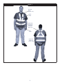
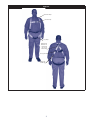
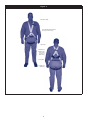
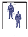
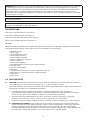
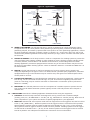
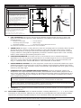
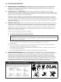
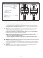
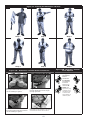
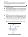
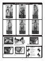
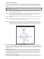
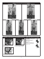
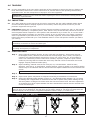
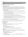
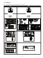
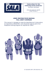
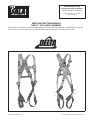
Instructions for the
following series products:
DELTA™ Full Body Harnesses
(See back pages for specific
model numbers.)
USER INSTRUCTION MANUAL
DELTA™ FULL BODY HARNESS
This manual is intended to meet the Manufacturer’s Instructions as required by ANSIZ359.1 and CSA
259.10 and should be used as part of an employee training program as required by OSHA
Form: 5903124 Rev: F
© Copyright 2012, DB Industries, Inc.
Figure 1
Shoulder
Strap
(inside vest)
Chest
Strap
Attachment
Element for
Fall Arrest
(D-ring or
Web Loop)
Leg
Strap
Labels and
RFID Tag
(inside vest)
2
Figure 2
Shoulder Strap
Chest Strap
Leg Strap
Attachment
Element for
Fall Arrest
(D-ring or
Web Loop)
D-ring Pad
Labels and
RFID Tag
3
Figure 3
Shoulder Strap
Front Attachment Element
(D-ring or Web Loop)
Leg Strap
Attachment
Element for
Fall Arrest
(D-ring or
Web Loop)
D-ring Pad
Labels and
RFID Tag
4
Figure 4
Shoulder Strap
Front D-ring
Leg Strap
Attachment
Element for
Fall Arrest
(D-ring or
Web Loop)
D-ring Pad
Labels and
RFID Tag
5
WARNING: This product is part of a personal fall arrest, restraint, work positioning, personnel riding, climbing,
or rescue system. The user must follow the manufacturer’s instructions for each component of the system.
These instructions must be provided to the user of this equipment. The user must read and understand these
instructions before using this equipment. Manufacturer’s instructions must be followed for proper use and
maintenance of this equipment. Alterations or misuse of this product or failure to follow instructions may result
in serious injury or death.
IMPORTANT: If you have questions on the use, care, or suitability of this equipment for your application,
contact Capital Safety.
IMPORTANT: Before using this equipment, record the product identification information from the ID label in the
inspection and maintenance log of this manual.
DESCRIPTIONS
Delta Vest™ Full Body Harness: See Figure 1.
Vest Style Full Body Harness: See Figure 2.
Cross-Over Style Full Body Harness: See Figure 3.
Step-In Style Full Body Harness: See Figure 4.
OPTIONS:
DBI‑SALA Full Body Harnesses are available with options and accessories. Following is a partial list of commonly
used options and accessories (some options may not be available on all harnesses):
•Shoulder D-rings
•Side D-rings
•Hip pad with side D-rings
•Quick Connect buckles
•Tongue buckle body belt
•Loops on harness for body belt
•Kevlar® webbing
•High visibility webbing
•Non-sparking/Non conductive PVC coated hardware
•Shoulder pads
•Tool belt support straps
•Seat sling
•Lanyard attached directly to D-ring or attachment element
•Snap fastener on shoulder strap for retaining lanyard
•Delta Vest™
•Tool holders
1.0APPLICATIONS
1.1PURPOSE: DBI‑SALA full body harnesses are to be used as components in personal fall arrest, restraint,
work positioning, or rescue systems. See Figures 1, 2, 3, and 4 for harness styles.
arnesses included in this manual are full body harnesses and meet ANSI Z359.1, OSHA, and CSA Z259.10
H
requirements. See Figure 5 for application illustrations.
•
Full body harnesses with Kevlar web should be used when working with tools, materials, or
environments of high temperature (foundries, chemical manufacturing, steel fabrication, emergency
rescue services, fire services, welders, oil industry, nuclear industry, explosives).
•
Harnesses with PVC coated hardware should be used when working in explosive or electrically
conductive environments, or where surfaces must be protected from the hardware.
•
Harnesses with high visibility webbing should be used when increased visibility of the user is required.
A. PERSONAL FALL ARREST: The full body harness is used as a component of a personal fall arrest
system. Personal fall arrest systems typically include a full body harness and a connecting subsystem
(energy absorbing lanyard). Maximum arresting force must not exceed 1,800 lbs (8 kN).For fall
protection applications connect the fall arrest subsystem (example: lanyard, SRL, energy absorber, etc.)
to the D-ring or attachment element on your back, between your shoulder blades.
6
Figure 5 - Applications
Anchorage
Anchorage Connector
Anchorage
Anchorage Connector
Connecting Subsystem
(Self Retracting Lifeline
Shown)
Full Body Harness
Full Body Harness
Restraint
Fall Arrest
Anchorage
Ladder
Anchorage
Connector
Cable Sleeve
Back-up Fall
Arrest System
Restraint Lanyard
Full Body
Harness
Restraint Lanyard
Anchorage
Cross-over
Full Body
Harness
Cable
Anchorage
Connector
Work Positioning
Ladder Climbing
B. WORK POSITIONING: The full body harness is used as a component of a work positioning system
to support the user at a work position. Work positioning systems typically include a full body harness,
positioning lanyard, and a back-up personal fall arrest system. For work positioning applications, connect
the work positioning subsystem (example: lanyard, Y-lanyard, etc.) to the lower (hip level) side or belt
mounted work positioning attachment anchorage elements (D‑rings). Never use these connection points
for fall arrest.
C. LADDER CLIMBING: The full body harness is used as a component of a climbing system to prevent the
user from falling when climbing a ladder or other climbing structure. Climbing systems typically include
a full body harness, vertical cable or rail attached to the structure, and climbing sleeve.For ladder
climbing applications, harnesses equipped with a frontal D-ring in the sternal location may be used for
fall arrest on fixed ladder climbing systems. These are defined in Z259.2.1 in Canada and ANSI A14.3 in
the United States.
D.RESCUE: The full body harness is used as a component of a rescue system. Rescue systems are
configured depending on the type of rescue. For limited access (confined space) applications, harnesses
equipped with D-rings on the shoulders may be used for entry and egress into confined spaces where
worker profile is an issue.
E. CONTROLLED DESCENT: For controlled descent applications, harnesses equipped with a single sternal
level D‑ring, one or two frontal mounted D‑rings, or a pair of connectors originating below the waist
(such as a seat sling) may be used for connection to a descender or evacuation system (reference in
Z259.10 in Canada).
F.RESTRAINT: The full body harness is used as a component of a restraint system to prevent the user
from reaching a fall hazard. Restraint systems typically include a full body harness and a lanyard or
restraint line.
1.2LIMITATIONS: Consider the following application limitations before using this equipment:
• CAPACITY: These full body harnesses are designed for use by persons with a combined weight
(clothing, tools, etc.) for ANSI Z359.1--310 lbs (141 kg), CSA Z259.10--352 lbs (160 kg). Make sure all
of the components in your system are rated to a capacity appropriate to your application
• FREE FALL: Personal fall arrest systems used with this equipment must be rigged to limit the free fall to
6 feet (1.8 M) (ANSI Z359.1). Restraint systems must be rigged so that no vertical free fall is possible.
Work positioning systems must be rigged so that free fall is limited to 2 feet (.6 m) or less. Personnel
riding systems must be rigged so that no vertical free fall is possible. Climbing systems must be rigged
so that free fall is limited to 18 in. (.46 cm) or less. Rescue systems must be rigged so that no vertical
free fall is possible. See subsystem manufacturer’s instructions for more information.
7
Figure 6 - Fall Clearance
Figure 7 - Swing Falls
RD = LL + DD + HH + C
RD
Required Fall Clearance Distance
LL
Length of Lanyard (Specified on labeling)
DD
Deceleration Distance = 4 ft (1.2 m) except:
•for ANSI/OSHA Lanyards with Free Fall
greater than 6 ft (1.8 m) up to 12 ft (3.7
m), or user weights greater than 310 lbs
(141 kg) up to 420 lbs (191 kg); add 1 ft
(0.3 m): DD = 5 ft (1.5 m)
•for CSA E6 Lanyards, add 1.7 ft. (0.5 m):
DD = 5.7 ft (1.7 m)
HH
Height of Suspended Worker
C
Safety Factor = 1.5 ft (0.5 m)
(Factors in D-Ring Slide and Harness Stretch.)
LL
RD
Swing
Fall
Hazard
DD
HH
Example: Assuming a 6 ft (1.8 m) tall user with a
typical 6 ft (1.8 m) lanyard with 6 ft (1.8 m) Free Fall,
Fall Clearance calculation would be as follows:
RD = LL + DD + HH + C
RD = 6 ft + 4 ft + 6 ft + 1.5 ft = 17.5 ft
RD = 1.8 m + 1.2 m + 1.8 m + 0.5 m = 5.3 m
C
• FALL CLEARANCE: See Figure 6. There must be sufficient clearance below the user to arrest a fall
before the user strikes the ground or other obstruction. The clearance required is dependent on the
following factors:
•
•
•
See
Elevation of Anchorage
• Free fall distance
Connecting subsystem length
• Worker height
Deceleration distance
• Movement of harness attachment element
subsystem manufacturer’s instructions for more information
• SWING FALLS: See Figure 7. Swing falls occur when the anchorage point is not directly above the point
where a fall occurs. The force of striking an object in a swing fall may cause serious injury or death.
Minimize swing falls by working as close to the anchorage point as possible. Do not permit a swing fall
if injury could occur. Swing falls will significantly increase the clearance required when a self- retracting
lifeline or other variable length connecting subsystem is used.
• EXTENDED SUSPENSION: A full body harness is not intended for use in extended suspension
applications. If the user is going to be suspended for an extended length of time it is recommended that
some form of seat support be used. DBI‑SALA recommends a seat board, suspension workseat, seat
sling, or a boatswain chair. Contact DBI‑SALA for more information on these items.
• ENVIRONMENTAL HAZARDS: Use of this equipment in areas with environmental hazards may require
additional precautions to prevent injury to the user or damage to the equipment. Hazards may include,
but are not limited to; heat, chemicals, corrosive environments, high voltage power lines, gases, moving
machinery, and sharp edges.
• HARNESSES FOR HIGH TEMPERATURE ENVIRONMENTS: Harnesses with Kevlar webbing are
designed for use in high temperature environments, with limitations: Kevlar webbing begins to char at
800° to 900° Fahrenheit. Kevlar webbing can withstand limited contact exposure to temperatures up to
1,000° F. Polyester webbing loses strength at 300° to 400° F. PVC coating on hardware has a melting
point of approximately 350° F.
IMPORTANT: When working with tools, materials, or in high temperature environments, ensure that associated
fall protection equipment can withstand high temperatures, or provide protection for those items.
IMPORTANT: Although PVC coated, cadmium, or zinc plated hardware exhibit excellent corrosion resistance in
chemical, acidic, alkaline, and atmospheric conditions, frequent inspections may be required. Consult with Capital
Safety if you question the use of this equipment in hazardous environments.
• TRAINING: This equipment must be installed and used by persons trained in its correct application and
use. See section 4.0.
1.3 APPLICABLE STANDARDS: Refer to national standards, including ANSI Z359 (.0, .1, .2, .3, and .4) family
of standards on fall protection, ANSI A10.32, CSA Z259.10, and applicable local, state and federal (OSHA)
requirements governing occupational safety for more information about work positioning systems.
IMPORTANT: Harnesses with Kevlar webbing do not meet ANSI Z359.1. Kevlar does not have equivalent abrasion
resistance of polyamides. Kevlar harnesses meet all other requirements of this standard.
8
2.0 SYSTEM REQUIREMENTS
2.1 COMPATIBILITY OF COMPONENTS: Capital Safety equipment is designed for use with Capital Safety
approved components and subsystems only. Substitutions or replacements made with non-approved
components or subsystems may jeopardize compatibility of equipment and may effect the safety and
reliability of the complete system.
2.2 COMPATIBILITY OF CONNECTORS: Connectors are considered to be compatible with connecting
elements when they have been designed to work together in such a way that their sizes and shapes do not
cause their gate mechanisms to inadvertently open regardless of how they become oriented. Contact Capital
Safety if you have any questions about compatibility.
Connectors (hooks, carabiners, and D-rings) must be capable of supporting at least 5,000 lbs. (22.2 kN).
Connectors must be compatible with the anchorage or other system components. Do not use equipment
that is not compatible. Non-compatible connectors may unintentionally disengage. See Figure 8. Connectors
must be compatible in size, shape, and strength. Self- locking snap hooks and carabiners are required by
ANSI Z359.1 and OSHA.
2.3 MAKING CONNECTIONS: Use only self-locking snap hooks and carabiners with this equipment. Use only
connectors that are suitable to each application. Ensure all connections are compatible in size, shape and
strength. Do not use equipment that is not compatible. Ensure all connectors are fully closed and locked.
Capital Safety connectors (snap hooks and carabiners) are designed to be used only as specified in each
product’s user’s instructions. See Figure 9 for inappropriate connections. Capital Safety snap hooks and
carabiners should not be connected:
To a D-ring to which another connector is attached.
A. To a D-ring to which another connector is attached.
B. In a manner that would result in a load on the gate.
NOTE: Large throat snap hooks should not be connected to standard size D-rings or similar objects which will
result in a load on the gate if the hook or D-ring twists or rotates, unless the snap hook complies with ANSI Z359.1
or ANSI Z359.12 and is equipped with a 3,600 lb (16 kN) gate. Check the marking on your snap hook to verify that
it is appropriate for your application.
C. In a false engagement, where features that protrude from the snap hook or carabiner catch on the
anchor, and without visual confirmation seems to be fully engaged to the anchor point.
D. To each other.
E. Directly to webbing or rope lanyard or tie-back (unless the manufacturer’s instructions for both the
lanyard and connector specifically allows such a connection).
F. To any object which is shaped or dimensioned such that the snap hook or carabiner will not close and
lock, or that roll-out could occur.
G. In a manner that does not allow the connector to align properly while under load.
2.4 CONNECTING SUBSYSTEMS: Connecting subsystems (self- retracting lifeline, lanyard, rope grab and
lifeline, cable sleeve) must be suitable for your application. See Section 1.1. See subsystem manufacturer’s
instructions for more information. Some harness models have web loop connection points. Do not use
snap hooks to connect to web loops. Use a self-locking carabiner to connect to a web loop. Ensure the
carabiner cannot cross-gate load (load against the gate rather than along the backbone of the carabiner).
Some lanyards are designed to choke onto a web loop to provide a compatible connection (see Figure 10).
Lanyards may be sewn directly to the web loop forming a permanent connection. Do not make multiple
connections onto one web loop, unless choking two lanyards onto a properly sized web loop.
Figure 8 - Unintentional Disengagement
If the connecting element to which a snap hook (shown) or carabiner attaches
is undersized or irregular in shape, a situation could occur where the connecting
element applies a force to the gate of the snap hook or carabiner. This force may
cause the gate (of either a self-locking or a non-locking snap hook) to open,
allowing the snap hook or carabiner to disengage from the connecting point.
Figure 9 - Inappropriate Connections
A.
B.
C.
D.
Small ring or other
non-compatibly
shaped element
E.
Force is applied to the
Snap Hook.
The Gate presses against
the Connecting Ring.
The Gate opens allowing
the Snap Hook to slip off.
9
F.
G.
Figure 10 - Web Loop Connections
Figure 11 - Front and Back of Delta Vest™ Harness
Insert lanyard web loop through
web loop or D-ring on harness
Harness Web Loop
or D-ring
Web Loop on
Energy Absorbing Lanyard
Insert appropriate end of lanyard
through the lanyard web loop
Pull the lanyard through the
connecting web loop to secure
2.5 ANCHORAGE STRENGTH: The anchorage strength required is dependent on the application type. The
following are the requirements of ANSI 359.1 for these application types:
A. FALL ARREST: Anchorages selected for fall arrest systems shall have a strength capable of sustaining
static loads applied in the directions permitted by the system of at least:
1. 5,000 lbs. (22.2 kN) for non-certified anchorages, or
2. Two times the maximum arresting force for certified anchorages. When more than one fall arrest
system is attached to an anchorage, the strengths set forth in (1) and (2) above shall be multiplied by
the number of systems attached to the anchorage.
B.RESTRAINT: Anchorages selected for restraint and travel restraint systems shall have a strength
capable of sustaining static loads applied in the directions permitted by the system of at least:
1. 1,000 lbs. (4.5 kN) for non-certified anchorages, or
2. Two times the foreseeable force for certified anchorages. When more than one restraint and travel
restraint system is attached to an anchorage, the strengths set forth in (1) and (2) above shall be
multiplied by the number of systems attached to the anchorage.
C. WORKING POSITIONING: Anchorages selected for work positioning systems shall have a strength
capable of sustaining static loads applied in the directions permitted by the system of at least:
1. 3,000 lbs. (13.3 kN) for non-certified anchorages, or
2. Two times the foreseeable force for certified anchorages. When more than one work positioning system is
attached to an anchorage, the strengths set forth in (1) and (2) above shall be multiplied by the number of systems
attached to the anchorage.
D.RESCUE: Anchorages selected for rescue systems shall have a strength capable of sustaining static loads applied
in the directions permitted by the system of at least:
1. 3,000 lbs. (13.3 kN) for non-certified anchorages, or
2. Five times the foreseeable force for certified anchorages. When more than one rescue system is attached to an
anchorage, the strengths set forth in (1) and (2) above shall be multiplied by the number of systems attached to
the anchorage.
E.CLIMBING: The structure to which a climbing system is attached must sustain the loads required by that
particular system. See instructions for climbing system for requirements.
10
3.0 DONNING AND USE
WARNING: Do not alter or intentionally misuse this equipment. Consult DBI‑SALA when using this equipment
in combination with components or subsystems other than those described in this manual. Some subsystem
and component combinations may interfere with the operation of this equipment. Use caution when using this
equipment around moving machinery, electrical and chemical hazards, and sharp edges.
WARNING: Consult your doctor if there is reason to doubt your fitness to safely absorb the shock from a fall
arrest. Age and fitness seriously affect a worker’s ability to withstand falls. Pregnant women or minors must
not use any DBI‑SALA full body harness.
3.1 BEFORE EACH USE of this equipment inspect it according to section 5.0 of this manual.
3.2 PLAN y
our system before use. Consider all factors that will affect your safety during use of this equipment.
The following list gives important points to consider when planning your system:
• ANCHORAGE: Select an anchorage that meets the requirements specified in sections 1.2 and 2.5.
• SHARP EDGES: Avoid working where system components may be in contact with, or abrade against,
unprotected sharp edges.
• AFTER A FALL: Components which have been subjected to the forces of arresting a fall must be
removed from service and destroyed.
• RESCUE: The employer must have a rescue plan when using this equipment. The employer must have
the ability to perform a rescue quickly and safely.
3.3 DONNING AND FITTING THE HARNESS:
Delta Vest™ Harness:
See Figure 11 for front and back views of the Delta Vest™ harness. Don the Delta Vest™ full body harness
by following these steps. (See Figures 12 and 13.)
Step 1. Lift harness by the back D-ring and untangle straps. Allow leg straps to hang free.
Step 2. Don the Vest Harness as you would a jacket. Do not zip the vest at this time.
Step 3. Connect chest strap by passing male buckle through female buckle. Pass excess webbing through
loop keepers.
Step 4. Reach between legs and grasp the leg strap on your left side. Bring the strap up between your
legs and connect to buckle attached to yellow strap (orange on high visibility models, black on
flame resistant models) as shown in Figures 12 and 13. Connect right leg strap.
Step 5. Reach inside the vest and adjust shoulder straps to a snug fit. Left and right shoulder straps
should be adjusted to the same length. Readjust leg straps, chest strap, and shoulder straps as
necessary to a snug fit.
Step 6. Zip the vest.
11
Figure 12 - Donning the Delta Vest™ Harness
Step 1
Step 2
Step 3
Step 4
Step 5
Step 6
Figure 13B - Revolver™ Vertical
Torso Adjuster
Figure 13A - Delta Vest™ Harness Buckle Connections
Right
A
Chest Strap: Pass male buckle
through female buckle and pull free
end of webbing to tighten.
Tongue Buckle: Pass webbing
through buckle and insert tongue
through grommet.
Pass Buckle: Pass male buckle
through female buckle and pull free
end of webbing to tighten.
Quick Connect Buckle: Insert the tab of
the buckle into the receptor of the quick
connect buckle until a click is heard.
12
To Tighten:
Turn Ratchet
Knob in
direction A.
Left
A
To Loosen:
Pull Ratchet
Knob out
and turn in
direction B.
B
NOTE: After
adjustment, tug
upwards on the
shoulder straps
to ensure that
each adjustor is
locked in place.
B
Vest Style Harness:
If your harness incorporates loops for a removable waist belt, the belt should be installed through the four
loops in the harness as shown in Figure 14. The hip pad, if used, is secured to the belt by passing the belt
through the hip pad loops. Don the vest style full body harness by following these steps (see Figures 1416B):
NOTE: Vest Style harnesses contain different harness buckle connections. See Figure 16A for the style
that applies to your harness.
Step 1. Locate back D-ring held in position by the D-ring pad; lift up harness and hold by this D-ring.
Ensure the straps are not twisted.
Step 2. Grasp the shoulder straps and slip harness onto one arm. D-ring will be located on your back side.
Ensure straps are not tangled and hang freely. Slip free arm into harness and position shoulder
straps on top of shoulder. Chest strap buckle will be positioned on front side when worn properly.
Pass excess strap through the loop keepers.
Step 3. Reach between your legs and grasp the leg strap on your left side. Bring the strap up between
your legs and connect it as shown in Figure 16A. Pull the free end of the strap away from the
buckle to make a snug fit on each leg strap. To loosen the leg strap, grasp the buckle and pull
away from your leg to allow the strap to pull through the buckle. A plastic end keeper on the end
of the strap will stop it from pulling completely out of the buckle. To release the buckle. Repeat
this procedure for the right side.
Step 4. Adjust the waist belt by inserting the buckle tongue into the grommet on the left side as shown in
Figure 16A.
Step 5. Attach the chest strap by connecting the buckle. See Figure 16A. Chest strap should be six inches
down from the top of shoulders. Pass excess strap through the loop keepers. The strap may be
tightened to a snug fit by pulling the free strap end to the left (away from the buckle). To loosen
the chest strap, grasp the buckle and pull away from the body to allow the strap to pull through
the buckle. A plastic end keeper on the end of the strap will stop it from pulling completely out of
the buckle.
Step 6.Adjust shoulder straps to a snug fit (Figure 16B). Left and right sides of shoulder straps should
be adjusted to the same length and the chest strap should be centered on your lower chest,
six inches down from shoulder. The front D‑ring on vest style harness is moved up or down by
adjusting the shoulder straps and leg straps. Center the back D-ring between shoulder blades.
Adjust leg straps to a snug fit. At least three inches of webbing must extend past buckle on leg
straps. Adjust the waist belt (if present). Center retrieval D-rings (if present) on top of each
shoulder.
Figure 14 - Removable Waist Belt & Hip Pad
13
Figure 15 - Donning Vest Style Harness
Step 1
Step 2
Step 3
Step 4
Step 5
Step 6
Figure 16A - Vest Style Harness Buckle Connections
Chest Strap: Pass male buckle
through female buckle and pull
free end of webbing to tighten.
Chest Strap: Attach chest strap by
inserting the tab of the buckle into the
receptor of the quick connect buckle
until a click is heard.
Tongue Buckle: Pass webbing through
buckle and insert tongue through grommet.
16B - Revolver™ Vertical Torso Adjusters
Right
Quick Connect Buckle: Insert the
tab of the buckle into the receptor of
the quick connect buckle until a click is
heard.
14
Left
To Loosen: Pull
Ratchet Knob
out and turn in
direction B.
A
Pass Buckle: Pass male buckle
through female buckle and pull
free end of webbing to tighten.
To Tighten: Turn
Ratchet Knob in
direction A.
B
NOTE: After
adjustment, tug
upwards on the
shoulder straps to
ensure that each
adjustor is locked in
place.
A
B
CROSS-OVER STYLE HARNESS:
If your harness incorporates loops for a removable waist belt, the belt should be installed through the four
loops in the harness as shown in Figure 17. The hip pad, if used, is secured to the belt by passing the belt
through the hip pad loops. Don the cross-over style full body harness by following these steps (see Figures
17-19B):
NOTE: Cross-Over Style harnesses contain different harness buckle connections. See Figure 19A for the
style that applies to your harness.
Step 1. Locate back D-ring held in position by the D-ring pad; lift up harness and hold by this D-ring.
Ensure the straps are not twisted.
Step 2. Grasp shoulder straps between back and front D-ring and slip harness over your head from the
left side. Position shoulder straps on top of shoulder. Ensure straps are not tangled and hang
freely. The D-ring will be positioned on your back when worn properly.
Step 3. Grasp the buckle below the front D-ring and connect (Figure 19A). Ensure straps are not tangled
or crossed.
Step 4. Reach between legs and grasp blue leg strap on your left side. Bring strap up between legs and
connect to buckle. Connect right leg strap (Figure 19A).
Step 5. Adjust shoulder straps to a snug fit (Figure 19B). Left and right sides of shoulder straps should
be adjusted to the same length and the front D-ring should be centered on your lower chest. The
back D-ring should be centered between your shoulder blades. Adjust leg straps to a snug fit.
Adjust the waist belt (if present). Center retrieval D-rings (if present) on top of each shoulder.
Figure 17 - Removable Waist Belt and Hip Pad
3.4 USE OF FALL ARREST D-RING OR ATTACHMENT ELEMENT: For fall protection applications connect to
the D-ring or attachment element on your back, between your shoulder blades. Side D‑rings, if present, are
for positioning or restraint applications only. Shoulder retrieval D-rings are for rescue or retrieval applications
only. Front D-ring is for ladder climbing or positioning. D-rings on seat sling are for suspension or positioning
applications only.
3.5 MAKING CONNECTIONS: When using a hook to connect to an anchorage or when coupling components
of the system together, ensure roll-out cannot occur. Roll-out occurs when interference between the hook
and mating connector causes the hook gate to unintentionally open and release. Self-locking snap hooks
and carabiners should be used to reduce the possibility of roll-out. Do not use hooks or connectors that
will not completely close over the attachment object. See subsystem manufacturer’s instructions for more
information on making connections.
3.6 CONNECTING SYSTEM COMPONENTS: After fitting the full body harness the user may then connect to
other system components. Follow the guidelines in section 3.4 on selecting the correct attachment element.
15
Figure 18 - Donning Cross-over Style Harness
Step 1
Step 3
Step 2
Step 4
Figure 19A - Cross-over Style Harness Buckle Connections
Step 5
Figure 19B - Revolver Torso Adjuster
To Tighten: Turn Ratchet Knob
in direction A.
Left
To Loosen: Pull Ratchet
Knob out and turn in
direction B.
Tongue Buckle: Pass webbing
through buckle and insert tongue
through grommet.
Pass Buckle: Pass male buckle
through female buckle and pull
free end of webbing to tighten.
Quick Connect Buckle: Insert the tab of
the buckle into the receptor of the quick
connect buckle until a click is heard.
16
A
NOTE: After adjustment, tug
upwards on the shoulder straps
to ensure that each adjustor is
locked in place.
B
4.0TRAINING
4.1
It is the responsibility of the user and the purchaser of this equipment to assure that they are familiar with
these instructions, trained in the correct care and use of, and are aware of the operating characteristics,
application limits, and the consequences of improper use of this equipment.
IMPORTANT: Training must be conducted without exposing the user to a fall hazard. Training should be
repeated on a periodic basis.
5.0INSPECTION
5.1
The i-Safe™ RFID tag on this harness can be used in conjunction with the i-Safe handheld reading device
and the web based portal to simplify inspection and inventory control and provide records for your fall
protection equipment See Figure 20.
5.2FREQUENCY: Before each use inspect the full body harness according to sections 5.3 and 5.4. The harness
must also be inspected by a competent person, other than the user, at least annually. Record the results of
each Competent Person inspection in the inspection and maintenance log in section 9.0, or use the i-Safe™
inspection web portal to maintain your inspection records. If you are a first-time user, contact a Customer
Service representative (See Back Cover) or if you have already registered, access isafe.capitalsafety.com.
Follow instructions provided with your i-Safe handheld reader or on the web portal to transfer your data to
your web log.
IMPORTANT: If the full body harness has been subjected to fall arrest or impact forces it must be
immediately removed from service and destroyed.
IMPORTANT: Extreme working conditions (harsh environments, prolonged use, etc.) may require
increasing the frequency of inspections.
5.3 INSPECTION STEPS:
Step 1. Inspect harness hardware (buckles, D-rings, back pad, loop keepers); These items must not
be damaged, broken, distorted, and must be free of sharp edges, burrs, cracks, worn parts, or
corrosion. PVC coated hardware must be free of cuts, rips, tears, holes, etc. in the coating to
ensure non-conductivity. Ensure buckles work smoothly. If present, inspect the quick connect
buckles by ensuring that the release tabs work freely and that a click is heard when the buckle
engages. Inspect parachute buckle spring.
Step 2. Inspect webbing; material must be free of frayed, cut, or broken fibers. Check for tears,
abrasions, mold, burns, or discoloration. Inspect stitching; Check for pulled or cut stitches. Broken
stitches may be an indication that the harness has been impact loaded and must be removed from
service.
IMPORTANT: On Delta Vest™ harnesses, inspection should include the webbing inside the vest.
Step 3. Inspect labels; All labels should be present and fully legible. See section 8.0.
Step 4. Inspect each system component or subsystem according to manufacturer’s instructions.
Step 5. Inspect the Stitched Impact Indicator (Figure 21): The Stitched Impact Indicator (A) is a section
of webbing that is lapped back on itself and secured with a specific stitch pattern holding the lap.
The stitch pattern is designed to release when the harness arrests a fall or has been subjected to
an equivalent force If the impact indicator has been activated the harness must be removed from
service and destroyed.
NOTE: Some harnesses are equipped with a “stand up D-ring” in the dorsal (back) D-ring location. If the
spring in the D-ring is damaged or lost and the D-ring no longer stands up, this does not compromise the
harness integrity. As long as the D-ring passes inspection criteria in Step 1, it is safe to use.
Figure 20 - i-Safe™ RFID Tag
Figure 21 - Stitched Impact Indicator
A
17
A
5.4DEFECTS: If inspection reveals a defective condition, remove unit from service immediately and destroy.
NOTE: Only DBI‑SALA or parties authorized in writing may make repairs to this equipment.
5.5 PRODUCT LIFE: The functional life of DBI-SALA harnesses is determined by work conditions and
maintenance. As long as the product passes inspection criteria, it may remain in service.
6.0 MAINTENANCE, SERVICING, STORAGE
6.1 WASHING INSTRUCTIONS:
Full body harness: Clean full body harness with water and a mild soap solution. Do not use bleach or
bleach solutions. Wipe off hardware with a clean, dry cloth, and hang to air dry. Do not force dry with heat.
An excessive buildup of dirt, paint, etc. may prevent the full body harness from working properly, and in
severe cases degrade the webbing to a point where it weakens and should be removed from service. More
information on cleaning is available from DBI‑SALA. If you have questions concerning the condition of your
harness, or have any doubt about putting it into service contact DBI‑SALA.
Fire Resistant Padding:
•
Remove pads from harness for laundering. Place the harness in the supplied laundry bag. The bag is
designed to prevent entanglement of harness and to protect the washing machine from damage. Use of
the laundry bag to wash the pads is optional.
•
Launder flame resistant pads separately from harness or other non-flame resistant garments. Lint from
other garments may affect flame resistance.
•
Use a bleach-free detergent when washing both the harness and the pads. Do not use soap; soap may
leave a residue which could affect flame resistance.
•
Do not use chlorine bleach. Bleach may weaken fabric and reduce product life.
•
Oily or greasy stains may be pre-treated and washed in hot water 140°F max (60°C max).
•
Use delicate, permanent press, or cotton sturdy wash cycle with cold or warm water. Hot water can be
used on heavily soiled items as long as it does not exceed 140°F (60°C). Use extra rinse cycle to be sure
all residual wash chemicals are removed.
•
Air dry or tumble dry using permanent press cycle and low heat. Drying temp should not exceed 200°F
(93°C). These fabrics dry quickly, for lowest shrinkage, do not over dry.
6.2
Additional maintenance and servicing procedures must be completed by a factory authorized service center.
Authorization must be in writing. Do not attempt to disassemble the unit.
6.3
Store full body harnesses in a cool, dry, clean environment out of direct sunlight. Avoid areas where
chemical vapors may exist. Thoroughly inspect the full body harness after extended storage.
7.0SPECIFICATIONS
7.1PERFORMANCE
Maximum Free Fall Distance: No greater than 6 feet (1.8 m), per federal law and ANSI Z359.1.
Maximum Arresting Force: 1,800 lbs. (8 kN)
Capacity: ANSI Z359.1--310 lbs (141 kg), CSA Z259.10---352 lbs (160 kg)
Approximate Weight:
• Harness only: 3 lbs. (1.4 kg)
• Harness with Side D-rings: Add 1/2 lb. (.23 kg)
• Harness with Back Pad or Belt: Add 1 lb. (.45 kg)
Cross-over Style Harness Patent numbers: United States: 5,203,829, C
anada: 2,080,643
All harnesses, excluding Kevlar harnesses, meet ANSI Z359.1 and OSHA requirements.
7.1MATERIALS
Standards: All harnesses marked with ASTM F887-2004 meet all testing requirements of the standard.
Webbing Materials: 6,000 lbs (27kN) Tensile Strength Polyester; 7,000 lbs (31 kN) Tensile Strength Nylon;
7,000 lbs. (31 kN) Tensile Strength Nomex™ covered Kevlar™.
Pad and Label Cover Materials:
• All outer fabric is Nomex and Kevlar blend fabric
• Fire resistant hook and loop fasteners
Optional Accessories:
• Hip Pad with side D-ring
•
• Nomex covered Kevlar webbing
•
• Non-sparking/ Non-conductive PVC coated hardware
18
Arc-rated hip, leg, and back pads
Polyurethane coated, arc-rated dorsal web loop
8.0LABELING
8.1
The following labels must be present and completely legible:
ANSI
CSA
RFID Tag
RFID Tag
Size Label
Size Label
Made in Canada
19
Made in USA
This instruction applies to the following models:
1100373
1100374
1100379
1100380
1100389
1100390
1100391
1100392
1100393
1100394
1100395
1100396
1100517
1100518
1100519
1100523
1100632
1100633
1100634
1100635
1100636
1100637
1100638
1100639
1100680
1100681
1100682
1100683
1100696
1100697
1100698
1100699
1100700
1100701
1100702
1100703
1100745
1100746
1100747
1100748
1100785
1100786
1100787
1100788
1100795
1100796
1100797
1100798
1100821
1100822
1100823
1100824
1100834
1100835
1100836
1100837
1100840
1100841
1100842
1100845
1100846
1100847
1100848
1100881
1100882
1100883
1100884
1100885
1100886
1100887
1100888
1100935
1100936
1100937
1100938
1101251
1101251H
1101252
1101252H
1101253
1101253H
1101254
1101254H
1101255
1101255H
1101256
1101257
1101258
1101258H
1101261
1101263
1101264
1101265
1101266
1101267
1101268
1101271
1101637
1101639
1101640
1101649
1101653
1101653H
1101654
1101654H
1101655
1101655H
1101656
1101656H
1101659
1101660
1101661
1101662
1101662H
1101776
1101781
1101783
1101784
1101785
1101786
1101787
1101791
1101794
1101796
1101800
1101801
1101802
1101803
1101805
1101806
1101807
1101808
1101809
1101810
1101811
1101812
1101813
1101814
1101815
1101816
1101817
1101818
1101819
1101820
1101821
1101822
1101826
1101827
1101828
1101829
1101830
1101831
1101838
1101839
1101840
1101841
1101842
1101843
1101844
1101846
1101847
1101854
1101855
1101856
1101857
1101858
1101858H
1101860
1101862
1101871
1102000
1102000H
1102001
1102008
1102008H
1102010
1102020
1102021
1102022
1102090
1102091
1102092
1102093
1102186
1102187
1102188
1102189
1102195H
1102196H
1102197H
1102198H
1102199H
1102200
1102201
1102201H
1102205
1102206
1102220H
1102221H
1102249
1102258
1102259
1102260
1102336H
1102337H
1102338H
1102339H
1102515
1102516
1102517
1102518
1102519
1102695
1102695H
1102950
1102950H
1102951
1102952
1102955
1102957
1102972
1103104
1103104H
1103109H
1103251
1103252
1103253
1103254
1103255
1103256
1103257
1103258
1103259
1103260
1103261
1103262
1103263
1103265
1103266
1103270
1103321
1103375
1103376
1103377
1103378
1103379
1103380
1103382
1103383
1103384
1103385
1103386
1103393
1103394
1103395
1103511
1103513
1103513H
1103875
1103876
1103877
1103878
1103879
1104625
1104626
1104627
1104628
1104629
1104632
1104633
1104635
1104636
1104875
1104875H
1104876
1104877
1104878
1104879
1104880
1104881
1104882
1104883
1104886
1104887
1104888
1104889
1104907
1104911
1104915
1105331
1105332
1105333
1105900
1105901
1105925
1105926
1105975
1105996
1106015
1106020
1106023
1106024
1106025
1106028
1106028H
1106035
1106040
1106041
1106055
1106066
1106081
1106089
1106092
1106092H
1106097H
1106098H
1106180
1107000
1107001
1107002
1107003
1107004
1107005
1107075
1107651
1107653
1107656
1107658
1107726
1107774
1107775
1107776
1107777
1107778
1107800
1107800H
1107801
1107802
1107803
1107803H
1107804
1107805
1107806
1107806H
1107807
1107807H
1107809
1107810
1107811
1107812
1107813
1107814
1107815
1107817
1107817H
1107818
1107818H
1107819
1107850
1107851
20
1107852
1107859
1107860
1107861
1107862
1108025
1108026
1108125
1108126
1108127
1108128
1108129
1108130
1108131
1108132
1108133
1108134
1108135
1108175
1108176
1108177
1108178
1108179
1108180
1108181
1108182
1108183
1108184
1108185
1108186
1108187
1108188
1108190
1108192
1108302
1108305
1108311
1109040
1109050
1109052
1109062
1109107
1109142
1109400
1109449
1109980
1109981
1109982
1109983
1109984
1110575
1110575H
1110576
1110576H
1110577
1110577H
1110578
1110578H
1110582
1110582H
1110586
1110587
1110588
1110589
1110589H
1110590
1110591
1110592
1110593
1110594
1110600
1110600H
1110601
1110601H
1110602
1110603
1110605
1110606
1110606H
1110608
1110618
1110618H
1110625
1110626
1110627
1110628
1110700
1110701
1110702
1110704
1110725
1110726
1110727
1111000
1111001
1111002
1111003
1111004
1111100
1111101
1111102
1111103
1111104
1112000
1112001
1112002
1112003
1112004
1112007
1112008
1112009
1112010
1112011
1112026
1112027
1112050
1112051
1112052
1112053
1112075
1112082
1112125
1112126
1112127
1112128
1112129
1112150
1112174
1112175
1112176
1112177
1112178
1112179
1112180
1112228
1112252
1112330
1112331
1112332
1112333
1112334
1112350
1112375
1112376
1112377
1112401
1112402
1112404
1112450
1112450H
1112451
1112452
1112453
21
22
INSPECTION AND MAINTENANCE LOG
SERIAL NUMBER:
MODEL NUMBER:
DATE PURCHASED:
INSPECTION DATE
Approved By:
Approved By:
Approved By:
Approved By:
Approved By:
Approved By:
Approved By:
Approved By:
Approved By:
Approved By:
Approved By:
Approved By:
Approved By:
Approved By:
Approved By:
Approved By:
Approved By:
Approved By:
DATE OF FIRST USE:
INSPECTION ITEMS
NOTED
CORRECTIVE ACTION
MAINTENANCE
PERFORMED
LIMITED LIFETIME WARRANTY
Warranty to End User: D B Industries, Inc., dba CAPITAL SAFETY USA (“CAPITAL SAFETY”) warrants to the
original end user (“End User”) that its products are free from defects in materials and workmanship under
normal use and service. This warranty extends for the lifetime of the product from the date the product is
purchased by the End User, in new and unused condition, from a CAPITAL SAFETY authorized distributor.
CAPITAL SAFETY’S entire liability to End User and End User’s exclusive remedy under this warranty is limited
to the repair or replacement in kind of any defective product within its lifetime (as CAPITAL SAFETY in its sole
discretion determines and deems appropriate). No oral or written information or advice given by CAPITAL
SAFETY, its distributors, directors, officers, agents or employees shall create any different or additional
warranties or in any way increase the scope of this warranty. CAPITAL SAFETY will not accept liability for defects
that are the result of product abuse, misuse, alteration or modification, or for defects that are due to a failure to
install, maintain, or use the product in accordance with the manufacturer’s instructions.
CAPITAL SAFETY’S WARRANTY APPLIES ONLY TO THE END USER. THIS WARRANTY IS THE ONLY WARRANTY
APPLICABLE TO OUR PRODUCTS AND IS IN LIEU OF ALL OTHER WARRANTIES AND LIABILITIES, EXPRESSED
OR IMPLIED. CAPITAL SAFETY EXPRESSLY EXCLUDES AND DISCLAIMS ANY IMPLIED WARRANTIES OF
MERCHANTABILITY OR FITNESS FOR A PARTICULAR PURPOSE, AND SHALL NOT BE LIABLE FOR INCIDENTAL,
PUNITIVE OR CONSEQUENTIAL DAMAGES OF ANY NATURE, INCLUDING WITHOUT LIMITATION, LOST PROFITS,
REVENUES, OR PRODUCTIVITY, OR FOR BODILY INJURY OR DEATH OR LOSS OR DAMAGE TO PROPERTY, UNDER
ANY THEORY OF LIABILITY, INCLUDING WITHOUT LIMITATION, CONTRACT, WARRANTY, STRICT LIABILITY, TORT
(INCLUDING NEGLIGENCE) OR OTHER LEGAL OR EQUITABLE THEORY.
The Ultimate in Fall Protection
CSG USA & Latin America
3833 SALA Way
Red Wing, MN 55066-5005
Toll Free: 800.328.6146
Phone: 651.388.8282
Fax: 651.388.5065
[email protected]
CSG Canada
260 Export Boulevard
Mississauga, ON L5S 1Y9
Phone: 905.795.9333
Toll-Free: 800.387.7484
Fax: 888.387.7484
[email protected]
CSG Northern Europe
5a Merse Road
North Moons, Moat
Reditch, Worcestershire, UK
B98 9HL
Phone: + 44 (0)1527 548 000
Fax: + 44 (0)1527 591 000
[email protected]
CSG EMEA
(Europe, Middle East, Africa)
Le Broc Center
Z.I. 1ère Avenue
5600 M B.P. 15 06511
Carros
Le Broc Cedex
France
Phone: + 33 4 97 10 00 10
Fax: + 33 4 93 08 79 70
[email protected]
CSG Australia & New Zealand
95 Derby Street
Silverwater
Sydney NSW 2128
AUSTRALIA
Phone: +(61) 2 8753 7600
Toll-Free : 1 800 245 002 (AUS)
Toll-Free : 0800 212 505 (NZ)
Fax: +(61) 2 8753 7603
[email protected]
CSG Asia
Singapore:
16S, Enterprise Road
Singapore 627666
Phone: +65 - 65587758
Fax: +65 - 65587058
[email protected]
www.capitalsafety.com
I S O
9001
Shanghai:
Rm 1406, China Venturetech Plaza
819 Nan Jing Xi Rd,
Shanghai 200041, P R China
Phone: +86 21 62539050
Fax: +86 21 62539060