1
GEK-64460A Maintenance Manual
•
Low Voltage
Power Circuit Breakers
Types AKR-75/100 and AKS-50
AKR-6D-75
AKR-9D-100
AKS-5A-50
Low-Voltage Power Circuit Breakers
Table of Contents
Description
SECTION 1-lntroduction
1.1
1.2
Frame Size
Operation
Mounting
Trip Device
Short Circuit Ratings
SECTION 3-8torage, Safety and
Maintenance
3.1
3.2
3.3
Storage
Safety
Maintenance
SECTION 4-Breaker Operation
4.1
4.2
4.2.1
4.3
4.3.1
4.3.2
4.4
4.5
Manual Closing
Electrical Closing
Alternate Control Circuit
Connections
Stationary Breaker
Drawout Breaker
Tripping
Charging and Closing Using
the Maintenance Handle
SECTION 5-Contact Maintenance
5.1
5.1.1
5.1.2
5.2
5.2.1
5.3
5.4
5.5
5.5.1
5.5.2
5.6
5.7
5.8
5.9
5.10
5.10.1
5.10.2
5.10.3
5.10.4
5.11
Slow Closing the Breaker
Electrical Breaker
Manual Breaker
Arc Ouencher Removal and Inspection
Removal and Replacement
Separation of Front and Back Frames
Back Frame Assembly
Measuring Contact Force
Stationary Arcing Contacts
Stationary Main and Intermediate Contacts
Measuring Contact Wipe
Adjusting Contact Wipe
Measuring Contact Open Gap
Checking Contact Sequence
Replacement of Contacts
Stationary Arcing Contacts
Movable Arcing Contacts
Movable Main and Intermediate Contacts
Stationary Intermediate and Main Contacts
Assembly and Adjustment of Crossbar
© 1993 GEN ERAL ELECTRIC COMPANY
2
4
Inspection and Maintenance
4
Renewal Parts ...........•.................... 4
SECTION 2-General Description
2.1
2.2
2.3
2.4
2.5
Page
6
6
6
7
7
7
9
9
9
9
10
10
10
11
12
12
" 12
13
13
14
" 14
14
14
15
15
16
18
19
19
19
19
19
21
22
22
22
22
23
24
25
Page
Description
SECTION 6-Breaker Maintenance
6.1
6.2
6.3
6.3.1
6.3.2
6.3.3
6.4
6.4.1
6.4.2
6.4.3
6.4.4
6.5
6.5.1
6.5.2
6.5.3
6.6
6.7
Safety Precautions
Lubrication
Breaker Mechanism Adjustments
Trip Latch
Latch Buffer
Reset Latch Bearing and Prop
Electrical Mechanism
Control Components
Charging Motor
Motor Operator Unit
Spring Discharge Interlock
Manual Mechanism
Mechanism Part Replacement
Ratchet Pawl Replacement
Adjustments
Drawout Mechanism
Drawout Mechanism Lock
,
SECTION 7-Accessories
7.1
7.1.1
7.1.2
7.2
7.2.1
7.3
7.3.1
7.3.2
7.4
7.4.1
7.4.2
7.5
7.5.1
7.5.2
7.6
7.7
7.7.1
7.8
7.8.1
7.9
7.9.1
7.9.2
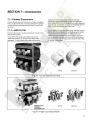
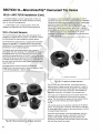
Primary Disconnects
AKR 75/100
AKSIAKST 50
Secondary Disconnects
Replacement
Auxiliary Switch
Replacement
Adjustments
Shunt Trip
Replacement
Adjustment
Undervoltage Device
Replacement
Adjustment
Static Time-Delay Undervoltage
Electric Lockout Device
AdJustment
Bell Alarm Device
Adjustment
Open Fuse Lockout Device
Coil Replacement
Adjustments
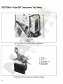
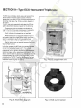
SECTION 8-Type SST Overcurrent
T'
.
np Devlce
8.1
8.2
8.2.1
8.2.2
8.3
8.4
8.4.1
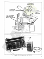
Programmer Unit
Current Sensors
Replacement of Current Sensors
- AKS 50
Replacement of Current Sensors
- AKR 75/100
Flux Shift Trip Device
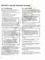
Troubleshooting
SST Test Set
26
26
, 26
26
26
26
26
28
28
29
30
32
32
33
35
35
36
36
37
37
37
38
39
39
40
40
40
41
41
41
42
42
42
43
44
44
45
45
46
46
46
47
47
48
50
51
51
54
54
Insert to document GEK-64459D and GEK-64460A
Breaker operation
This is an insert to the maintenance manuals for
AKR 30/50 (GEK 64459D) and AKR 75/100
(GEK64460A). The insert describes the operation of the
breaker with the newly introduced electronic closing
system.
For the AKR 30/50 insert to section 5 starting on
page 11.
For the AKR 75/100 insert to section 4 starting on
page 10
Replacement Parts
Replacement printed circuit board assembly for 48
VDC applications: #10060126G1
Replacement printed circuit board assembly for all
other voltage applications: #10060126G2
2/10/97
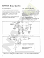
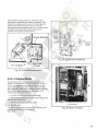
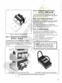
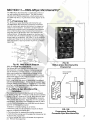
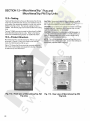
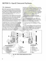
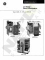
E.2 ELECTRICAL CLOSING
On electrically operated breakers the closing
springs are charged by a gear motor. With the springs
discharged, voltage applied to the control circuit will
energize the motor through the "G" switch contacts - see
Fig. E1. The motor, through the gear reduction output
crank, compresses the closing spring until they are fully
charged. As this fUlly charged position is reached,
mechanically operated switches "F" and "G" reverse their
shown position, the "G" switch deenergizing the motor
and the "F" switch establishing a circuit to the One-Shot
electronic.
With the closing spring propped fUlly-charged, the
breaker is ready for closing. This may be accomplished
electrically by depressing the closing switch "PB" on the
breaker (if so equipped) or by a remote closing switch.
Operation of the closing switch energizes the One-Shot
electronic, witch in turn energizes the closing solenoid
"CC". This removes the prop, releasing the closing
springs to close the breaker.
As the One-Shot electronic is energized through a
closing contact, the "X" relay is energized as well. The
"X" relay will latch in and therefore prevent a second
closing operation on the breaker in the event it is tripped
open automatically. The closing signal must be released
and reapplied before a second closing operation can
occur.
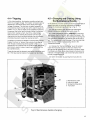
The closing springs on the electrically operated breakers
can be manually charged.
(X)
(+)
LEGEND
CC
F
G
L
M
PB
(Y)
(-)
FIG.E1 - ELEMENTARY DIAGRAM FOR
ELECTRICALLY OPERATED DRAWOUT BREAKER.
CONTACT POSITIONS ARE SHOWN WITH BREAKER
OPEN AND CLOSING SPRINGS DISCHARGED. TYP #
183L712 &# 568B736 "E" SERIES
X
OS
CLOSING SOLENOID
CUTOFF SWITCH, CLOSED WHEN
CLOSING SPRING IS FULLY
CHARGED.
CUTOFF SWITCH. OPEN WHEN
CLOSING SPRING IS FULLY
CHARGED.
AUXILIARY SWITCH
CHARGING MOTOR
CLOSE PUSH-BUTTON ON BREAKER
ESCUTCHEON, OPTIONAL.
CONTROL RELAY
ONE-SHOT ELECTRONIC. PULSES
THE CLOSING SOLENOID FOR
250 MSEC.
FIG. 13 - MANUAL OPERATION OF CLOSING SOLENOID
Table of Contents
Description
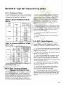
8.4.2
8.4.3
8.5
Page
Resistance Values
,
False Tripping - Breakers
Equipped with Ground Fault
SST Cabling Diagrams
55
,
SECTION 9-Type ECS
Overcurrent
Trip Device
9.1
55
55
"
"
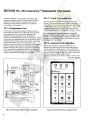
SECTION 10- MicroVersaTrip ™
Overcurrent
Trip Device
10.1
10.1.1
10.1.2
10.2
10.2.1
10.2.2
10.3
10.3.1
10.3.2
10.4
10.5
10.5.1
10.5.2
106
58
59
ECS Cabling Diagram
,
Programmer Unit
,
Fault Trip Indicators
Remote Fault Indication
,
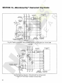
MicroVersaTrip TM Installation
,
AKS 50 Installation
,
AKR 50/100 Installation
,
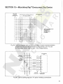
Current Sensors
Replacement of Currenl Sensors
- AKS 50
Replacement of Curent Sensors
- AKR 75/100
Flux Shift Trip Device
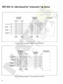
Troubleshooting
Resistance Values
,
False Tripping-Breakers
Equipped With Ground Fault
MicroVersaTrip TM Cabling Diagrams. . . . . . . . . . ..
SECTION 11-RMS-9/Epic
MicroVersaTrip®
11.1
11.1.1
11.2
11.3
11.3.1
11.4
11.5
11.5.1
11.5.2
11.6
60
60
60
60
62
62
63
64
65
65
65
65
66
67
67
71
Programmer Unit
Fault Trip Indicators
RMS-9 & Epic MicroVersaTrip Installation
Current Sensors
Replacement of Current Sensors
Flux Shifter Trip Device
Troubleshooting
Resistance Values
False Tripping-Breakers Equipped
With Ground Fault
,
Cabling Diagrams
71
71
71
72
75
75
75
75
'
76
76
SECTION 12-MicroVersaTrip Plus and
MicroVersaTrip PM Trip Units . ..
N
12.1
12.2
12.3
12.4
12.5
12.6
12.7
12.8
12.9
Trip Unit
Read This First
Product Structure
Trip Unit Removal and Replacement
Phase Current Sensors
Neutral Current Sensors
Rating Plug Removal and Replacement
Trip Unit Functions
Trouble-Shooting Guide
'
,
79
" 79
80
80
81
82
83
83
83
84
Description
Page
SECTION 13-Type EC
Overcurrent
Trip Device
13.1
13.1.1
13.1.2
13.1.3
13.1.4
13.2
13.3
13.4
13.4.1
13.4.2
13.4.3
13.5
13.5.1
13.5.2
13.5.3
13.5.4
13.6
13.7
13.7.1
13.7.2
13.8
13.9
Direct Acting Tripping Device EC-1 B
Long Time Delay Tripping
Short Time Delay Tripping
Instantaneous Tripping - High Set
Instantaneous Tripping - Low Set
,
Replacement
,..........................
Adjustments
Series Overcurrent Tripping
Device EC·2A
, .. , . . . . . . . . . . . . . . . . ..
Long Time-Delay and High Set
Instantaneous Tripping
,
Instantaneous Low Set Tripping
,
Instantaneous High Set Tripping
Series Overcurrent Tripping Device EC-1
Short Time-Delay Tripping
Long Time-Delay Tripping
Instantaneous Tripping
EC-1 Adjustment
Positive Trip Adjustment
Reverse Current Tripping Device
Adjustments
Replacements
Switchette Feature
,
Trip Device Replacement .,
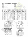
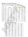
SECTION 14 - Electrical Characteristics ...
Table 23
Charging and Closing Operating Currents
Table 24
Bell Alarm Contact-Rating
Table 25
Auxiliary Switch Contact Sequence
Table 26
Auxiliary Switch Contact Ratings
Table 27
Charging Times
Table 28
Shunt Trip and Undervoltage Device
Table 29
Coil Resistance
Table 30
Instantaneous Undervoltage Device Settings
Table 31
Time-Delay Undervoltage Device Settings
85
87
87
87
87
87
87
88
89
89'
89
89
91
91
91
92
92
92
93
94
94
94
94
95
95
95
95
95
95
96
96
97
97
THESE INSTRUCTIONS ARE INTENDED FOR USE BY QUALIFIED
PERSONNEL FOR INSTRUCTION AND MAINTENANCE PURPOSES.
REPRODUCTION IN WHOLE OR IN PART IS NOT PERMITTED
WITHOUT THE EXPRESS PERMISSION OF GENERAL ELECTRIC.
3
SECTION 1-1 ntroduction
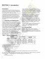
Introduction
These instructions provide the maintenance procedures
and describe the operation of the 1600 thru 4000 amp AC,
6000 amp DC frame size type AKR, AKS low voltage power
circuit breakers listed in Table 1 and Table 2.
The proper use, care and maintenance of these breakers is
a prime safety consideration for the protection of
personnel, as well as a means of minimizing equipment
damage when faults occur, Persons who apply, use, and
service these breakers will acquire the knowledge they
need by gaining the information contained in these
instructions,
1.1-lnspection and Maintenance
Breakers should be cared for under a systematic
maintenance program. Taking each breaker out of service
periodically for inspection and maintenance is an excellent
means of establishing high service reliability. It is good
policy to have one or more spare breakers to install in
place of breakers requiring maintenance. Keeping a stock
of recommended renewal parts will insure that
maintenance work can be done quickly.
How frequently an individual breaker should be inspected
will depend on the circumstances of its use. It would be
well to inspect any breaker at least once a year. If it is
frequently operated, or installed in an area of high
humidity or a dusty, dirty atmosphere, inspections should
be more often. Inspections might be monthly under
adverse conditions,
A basic maintenance inspection should consist of an
overall visual check, plus observation of a few closing and
opening operations. If a breaker is seldom operated such
that it remains open or closed for a period of six months or
more, it is recommended that arrangements be made to
open and close it several times in succession.
Dirt, grease or other foreign material on any parts of the
breaker should be removed by a thorough and careful
cleaning, Insulating surfaces should be checked for
conditions that could degrade insulating properties.
During an inspection, the breaker's contacts should be
slow-closed manually (with closing springs restrained by
the safety pin) to observe contact alignment and to insure
that all mechanism parts move freely, A complete contact
inspection, including measurement of wipe and force,
should also be done.
To properly inspect contacts, the arc quenchers must be
removed. At this time thoroughly inspect the inside
surfaces of the arc quencher side plates and inner
components,
1.2-Renewal Parts
The AKR breakers contain a variety of parts and
assemblies, Many of these parts and assemblies are
available as replacement parts when the need arises, See
publication GEF4552, Renewal parts, for a complete listing
of these parts.
Table 1-AKS 50 Designations
FRAME SIZE
(Amperes)
DRAWOUT MOUNTING
250V.Dc
600V. Ac
POLES
AKD
AKD-5
2000
1600
3
AKS-(*)-50
AKS-(*)-50H
AKS-(*)A-50
AKS-(*)A-50H
-
-
STATIONARY
MOUNTING
NOTES
AKS-(*)S-50
AKS-(*)S-SOH
(1 )
2
AKS-(*)-50V
AKS-(*)A-50V
AKS-(*)S-50V
(2)
-
2000
3
AKST-(*)-50H
AKST-(*)A-50H
AKST-(*)S-SOH
(1 )
-
1600
3
AKSU-(*)-50
AKSU-(*)A-50
-
(3)
(1) The "H" suffix denotes extended short circuit ratings.
(2) Integrally fLised models.
(*) This digit identifies the trip device type as follows:
2 = EC-1 or EC-2A (Dc only),
4 = ECS
S = SST
(50/60 Hertz only)
6 = MicroVersaTrip
N = Non automatic. In addition, all non-automatic 250 VDc breaker types carry the suffix letter D after their
frame number, e,q" AKS-N-50D.
EC-1 & EC-2A trip devices are the electro-mechanical type. ECS, SST, MicroVersaTrip'", RMS-9 and MVT-Plus or MVT-PM
units are Solid State. For detailed information on these trip devices refer to Sections 8 thru 11.
7 = RMS-9
9 MVT-PLUS or MVT-PM
=
4
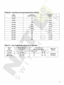
Table 2-AKR 75/100 Designations
FRAME SIZE
(Amperes)
2SOV. Dc
6OOV. Ac
50/60 Hz.
3000
4000
3200
3200
CD
6000
4000
MOUNTING TYPE
BREAKER
DESIGNATION
AKR-(*)-75
AKR-( *)A-75
AKR-(·) B-75
AKR-(*)G-75
AKR-(*)D-75
AKR-(*)F-75
AKR-( *)S-75
AKR-(*)D-75H
AKR-(*)F-75H
AKR-(*)-100
AKR-( ·)A-1 00
AKR-(·) B-100
AKR-(·)C-100
AKR-(·)D-100
AKR-(*)F-100
AKR-(·)S-100
AKR-(*)W-100
AKD
DRAWOUT
AKD-S AKD-6 AKD-8
Stationary
SubStructure
DEEP
ESCUTCHEON
X
X
X
X
X
X
X
X
X
X
X
X
X
X
X
X
X
X
X
X
X
X
X
X
X
X
PRIMARY
STUD
TYPE
Bar
Tube
Tube
Fingers
Fingers
Fingers
Fingers
Bar
Fingers
Fingers
Tube
Tube
Fingers
Fingers
Fingers
Fingers
Bar
Bar
BREAKER
WIDTH
(Inches)
25
25
33
25
33
SPECIAL DC BREAKERS FOR FIELD SWITCHING
4000
6000
ARK-N-75F
AKR-NB-75F
AKR-ND-75F
AKR-NF-75F
AKR-NS-75F
AKR-N-100F
AKR-N B-1 OOF
AKR-ND-100F
AKR-NF-100F
AKR-NS-100F
AKR-NW-100F
X
X
X
X
X
X
X
X
X
X
X
X
X
X
'\
X
X
X
Tube
Fingers
Fingers
Fingers
Bar
Tube
Fingers
Fingers
Fingers
Bar
Bar
25
33
25
33
Example: AKR-5B-75 identifies a drawout, substructure-mounted breaker equipped with the SST trip device.
The EC trip devices are electro-mechanical, refer to GEl 86157 for detailed information.
Breaker Models
(*) This digit identifies
the trip device:
2 = EC-1 B. Dc only,
4 = ECS
5 = SST 50/60 Hertz only.
6 = MicroVersaTrip 50/60 Hertz only.
7 = RMS-9
9 = MVT-PLUS or MVT-PM
N = Non-automatic.
In addition, all
non-automatic 250V.
Dc breaker types carry the
suffix letter D after the
frame number,
e.g., AKR-NB-75D.
CD AKR-75H not available for DC applications.
For detailed information on
these trip devices refer to
Sections 8 thru 11.
5
SECTION 2-General Description
General Description
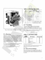
2.1-Frame Size
Type AKR low-voltage power circuit breakers are used for controlling and protecting power circuits in the low-voltage range
(usually up to 600 volts). In serving this function, they are a
means of safely switching loads and automatically clearing circuits when abnormal conditions occur. Among these conditions, the more common are short circuits and sustained
overloads and undervoltages.
AKR 75 breakers are available in three frame sizes-3200
amperes A.C. and 4000 amperes D.C. There is also
available, for replacement or hole filler application on AKD
or AKD5 switchgear a 3000 amperes A.C. frame.
The type AKR breakers are of the "quick-make, quickbreak" description, having the feature of storing energy in
a closing spring for quick release in closing. In closing,
some energy is transferred to an opening spring to be used
subsequently for fast tripping.
Knowledge of how the breaker is designed and how it
operates will enable the purchaser to make proper use of
the breaker and to avoid mistakes in its operation. Specific
directions on adjustments and maintenance procedures
will be treated later.
The three main functional components of a breaker are its
mechanism, an assembly comprising the conductive
members, and the interrupter.
The mechanism unit is designed to receive energy, store it,
and later (when called upon to do so) deliver it to close the
breaker contacts. It must be able to reverse its
commitment to close the breaker at any point upon the
activation of an automatic trip device (i.e., be "Trip-Free").
Finally, it also must be able to trip open a closed breaker
q\-licky enough to minimize arc erosion and in such a
manner as to effect proper arc transfer to the arc runner.
AKR 100 breakers are available in two frame sizes-4000
amperes A.C. and 6000 amperes D.C.
AKS 50 (replacement breaker for the AK50) is available in
two frame sizes-1600 amperes A.C. and 2000 amperes
A.C. or D.C. depending on trip device.
These values represent the maximum continuous current
capability of the respective frames. However, each breaker
carries a specific rating which is determined by the current
sensor ampere rating or tap setting of the trip device with
which it is equipped.
Individual breaker rating data is shown in Table 5.
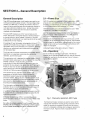
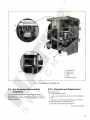
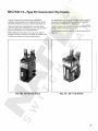
2.2-0 peration
There are Manual and Electrical models. The Manual
breaker has an operating handle which is used to manually
charge the mechanism closing spring. Figure 1 shows a
typical Manual breaker.
The current-carrying members of the breaker are
assembled on the back frame, which provides the
mechanical support required and also the insulating
structure needed. The conductive members are the studs
for external connections, movable and stationary contact
sets, pivots for the movable contacts, and provision for
mounting the current transformers.
The interrupter components are, in addition to the arcing
contacts, the arc runners mounted on the back base and
the removable arc quencher assemblies.
I n addition to these basic components, a breaker may be
equipped with any combination of many accessories and
interlocking devices.
Individual breakers may differ in a variety of areas as
shown in Tables 1 and 2. A brief description of these areas
follow.
An outline drawing Is available for each breaker frame size
showing critical dimensions. The drawing number appears
on the breaker nameplate and can be obtained from GE.
6
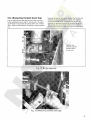
Fig. 1. Manually operated, AKD type
fhe Electrical breaker contains an electric motor which
charges the mechanism closing spring. External control
power is required to energize this motor and its control
circuit. A nameplate indicates what voltage is required by
the motor circuit. Figure 2 shows a typical Electrical
breaker.
Table 3-Mounting Type Codes
Code
Letter
Breaker Type
Drawout
Stationary
AKD
---
A
AKD-5,6
---
B
Substructure
C
AKD-6 Only
D
AKD-8
-------
F
Substructure
---
S
---
AKR-75/100 (25" wide)
W
---
AKR-100 (33" wide)
None
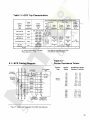
2.4-Trip Device
There are six types of solid-state, direct-acting selfpowered trip device systems associated with AKR
breakers. These systems are for AC applications only. For
DC applications an electromechanical system is available.
Fig. 2. Electrically operated, AKD type
The trip device system is identified by the first middle digit
in the breaker's nameplate designation as follows:
AKR-(t) C-75
(t) = trip device code per Table 4
2.3-Mounting
AKR-75 and -100 breakers are furnished in both drawout and
stationary construction. Drawout breakers are equipped with
features which make them easy to install in or withdraw from
their associated switch-gear equipment. Stationary breakers
are designed to be mounted in a switchboard or enclosure.
Mounting consists of bolting the breaker frame to a supporting structure within the switchboard or enclosure. If control
power connections are needed, a suitable terminal board is
supplied.
The mounting type is identified by the second middle digit
in the breaker nameplate designation as follows:
AKR-4(tJ-75, where
(t) = mounting type code letter per Table 3
Table 4- Trip Device Codes
CODE
NUMBER
2
3
4
5
6
7
9
TRIP DEVICE
EC'
Power Sensor 2
EC
SST
MicroVersaTrip
RMS-9
MVT-PLUS or MVT-PM
APPLICATION
DC
AC
AC
AC
AC
AC
AC
'EC devices. See Section 11.
2Power Sensor devices are discontinued. See publications
GEK-7301 and GEK-7309 for detailed servicing
procedures.
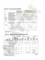
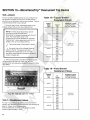
2.5-Short Circuit Ratings
Short circuit ratings vary with the applied system voltage. On
240 VAC systems they are also dependent upon whether the
overcurrent trip device contains an instantaneous trip element.
See Table 5.
7
Table 5- Breaker Interruption Ratings
30 Interruption Rating
KA RMS Symmetrical
Frame
Size
(Amperes)
Breaker
Type
AKS-50
1600 AC
Instantaneous Trip
Rated Maximum
Voltage (60 Hz AC)
With
Without
Short
Time
635
42
42
42
508
50
50
50
254
65
50
42
65
65
65
600
200
200
635
42
42
65
65
65
65
635
AKS-50H
508
254
AKSU-50
2000 AC
AKST-50H
508
42
254
635
AKR-75
508
85
65
85
85
254
130
85
600
200
200
85
85
254
3200 AC
65
635
AKR-75H
AKR-75 (fused)
508
635
AKR-100
85
-
85
508
4000 AC
254
130
85
AKR-100 (fused)
600
200
200
-
2000 DC
AKS50
AKS 50V
300V DC
50 CD
(2)
-
4000 DC
AKR 75
300V DC
50
50
6000 DC
AKR 100
300iJ DC
50
50
-
Q) With 200-2000 amp trip coils
®
8
Consult factory for application data
SECTION 3-Storage, Safety & Maintenance
3.1-Storage
It is recommended that the breaker be put into service
immediately in its permanent location. If this is not
possible, the following precautions must be taken to insure
the p roper storage of the breaker:
1. The breaker should be carefully protected against
condensation, preferably by storing it in a warm
dry room, since water absorption has an adverse
effect on the insulation parts. Circuit breakers for
outdoor switchgear should be stored in the
equipment only when power is available and the
heaters are in operation to prevent condensation.
2. The breaker should be stored in a clean location
free from corrosive gases or fumes. Particular care
should be taken to protect the equipment from
moisture and cement dust, as this combination has
a very corrosive effect on many parts.
CAUTION: IF THE BREAKER IS STORED FOR
ANY LENGTH OF TIME, IT SHOULD BE
INSPECTED PERIODICALLY TO SEE THAT
RUSTING HAS NOT STARTED AND TO
ASSURE GOOD MECHANICAL CONDITION.
SHOULD THE BREAKER BE STORED UNDER
UNFAVORABLE ATMOSPHERIC CONDITIONS. IT SHOULD BE CLEANED AND DRIED
OUT BEFORE BEING PLACED IN SERVICE.
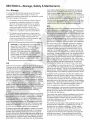
3.2
Each user must maintain a safety program for the protection
of personnel, as well as other equipment, from the potential
hazards associated with electrical equipment.
The following requirements are intended to augment the
user's safety program, but NOT supplant the user's responsibility for devising a complete safety program. The following basic industry practiced safety requirements are applicable to all major electrical equipment such as switchgear or
switchboards. General Electric neither condones nor assumes
any responsibility for practices which deviate from the following:
1. ALL CONDUCTORS MUST BE ASSUMED TO BE ENERGIZED UNLESS THEIR POTENTIAL HAS BEEN MEASURED AS
GROUND AND SUITABLE GROUNDING CONDUCTORS HAVE
BEEN APPLIED TO PREVENT ENERGIZING. Many accidents
have been caused by back feeds from a wide variety of
sources.
2. Although interlocks to reduce some of the risks are provided,
the individual's actions while performing service or maintenance
are essential to prevent accidents. Each person's knowledge;
his mental awareness; and his planned and executed actions
often determine if an accident will occur. The most important
method of avoiding accidents is for all associated personnel to
carefully apply a thorough :.Jnderstanding of the specific equiprrent from the viewpoints of it's purpose, it's construction, it's
opJration and the situations which could be hazardous.
All personnel associated with installation, operation and maintenance of electrical equipment, such as power circuit breakers
and other power handling equipment, must be thoroughly instructed, with periodic retraining, regarding power equipment in
general as well as the particular model of equipment with which
they are working. Instruction books, actual devices and appropriate safety and maintenance practices such as OSHA publica-
tions, National Electric Safety Code (ANSI C2), The National
Electrical Code, and NFPA 70B Electrical Equipment Maintenance must be closely studied and followed. During actual
work, supervision should audit practices to assure conformance.
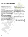
3. Excellent maintenance is essential for reliability and safety of
any electrical equipment. Industry publications of recommended maintenance practices such as ANSI/NFPA 70B, Electrical Equipment Maintenance, should be carefully studied and
applied in each user's formation of planned maintenance.
3.3
Both long and short term maintenance of all electrical equipment is essential for reliability and safety. Maintenance programs must be tuned to the specific application, well planned
and carried out consistent with both industry experience and
manufacturer's recommendations. Local environment must
always be considered in such programs, including such variables as ambient temperatures, extreme moisture, number of
operations, corrosive atmosphere or major insect problems
and any other unusual or abusive condition of the application.
One of the critical service activities, sometimes neglected,
involves the calibration of various control devices. These
monitor conditions in the primary and secondary circuits,
sometimes initiating emergency corrective action such as
opening or closing circuit breakers. In view of the vital role
of these deVices, it is important that a periodic test program
be followed. As was outlined above, it is recognized that the
interval between periodic checks will vary depending upon
environment, the type of device and the user's experience. It
is the General Electric recommendation that, until the user
has accumulated enough experience to select a test interval
better suited to his indiVidual requirements, all significant
calibrations be checked at an interval of one to two years.
To accomplish this, some items, such as "EC" direct operating
trip systems for low voltage breakers, must be tested with
primary current injection. Others can be adequately tested
using test sets. Specific calibration instructions on particular
devices typically are provided by supplied instruction books.
Instruction books supplied by manufacturers address components that would normaliy require service or maintenance
during the useful life of the equipment. However, they can
not include every possible part that could require attention,
particularly over a very long service period or under adverse
environments. Maintenance personnel must be alert to deterioration of any part of the supplied switchgear, taking actions, as necessary to restore it to serviceable status.
Industry publications of recommended maintenance practices
such as ANSIINFPA 70B, Electrical EqUipment Maintenance,
should be carefully studied and applied in each user's formation of planned maintenqnce.
Some users may require additional assistance from General
Electric in the planning and performance of maintenance.
The General Electric Company can be contracted to either
undertake maintenance or to provide technical assistance
such as the latest pUblications.
The performance and safety of this equipment may be compromised by the modification of supplied parts or their replacement by non identical substitutes. All such design
changes must be qualified to ANSI/IEEE Standard C37.59.
The user should methodically keep wr(tten maintenance
records as an aid in future service planning and equipment
reliability improvement. Unusual experiences should be
promptly communicated to the General Electric Company.
9
SECTION 4-Breaker Operation
Breaker Operation
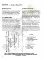
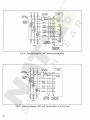
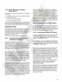
4.2-Electrical Closing
The AKS-50, AKR-75 and AKR-100 breakers are closed by
the discharging of the energy stored in the closing springs
of the breaker. As the closing springs are discharged, the
energy is directed into the closing cam of the breaker
which causes the moveable breaker contacts to be forced
against the stationary contacts, and, at the same time
causes the opening springs to be charged so they may
open the breaker during a subsequent opening operation.
On electrically operated breakers, the closing springs are
charged by a gear motor. With the springs discharged, voltage applied to the control circuit will energize the motor
through the "G" switch contacts-see figs. 3A & 3B. The motor, through the gear reduction output crank, compresses the
closing springs until they are fully charged. As this fully
charged position is reached, mechanically operated switch
"G" reverses its shown position, deenergizing the motor. In
the fig. 3A diagram switch "F" reverses its position and establishes a circuit for the "X" relay. At the same time, a mechanical prop is positioned to prevent the discharge of the
fully charged closing spring.
4.1-Manual Closing
Manually operated breakers are equipped with a handle
which extends from the escutcheon of the breaker.
Alternately rotating the closing handle counterclockwise
then clockwise through approximately 120 degrees of
rotation through four complete cycles will cause the
breaker to close. During the four counterclockwise
movements and the first three clockwise movements of the
handle, the springs are progressively charged. After
approximately seven degrees travel of the fourth clockwise
handle movement, the spring charge mechanism is driven
"over center" and the energy stored in the closing springs
is directed into the closing cam and causes the breaker to
close. A charge-indicator, numbered one to four, visible
through the breaker escutcheon, indicates the number of
complete handle movements that have been performed.
With the closing spring pr-opped fully-charged, the breaker
is ready for closing. This may be accomplished electrically
by depressing the closing button on the bre'aker (if so
equipped) or by a remote closing switch. Operation of the
closing switch energizes the "X" relay, which in turn
energizes the closing solenoid. This removes the prop,
releasing the closing springs to close the breaker.
As the closing relay is energized, it energizes anti-pump
relay "W". If the closing switch is maintained closed, the
anti-pump relay will remain picked-up to prevent a second
closing operation on the breaker in the event it is tripped
open automatically. The closing impulse must be released
and reapplied before a second closing operation can occur.
LEGEND
CC F-
CONTROL
SOURCE
CC
CUTOFF SWITCH, CLOSED
WHEN CLOSING SPRING IS
FULLY CHARGED.
G-
CUTOFF SWITCH. OPEN WHEN
CLOSING SPRING IS
FULLY CHARGED.
L-
AUXILIARY SWITCH
M-
CHARGING MOTOR
PB -
TC
CLOSING SOLENOID
TC WX-
CLOSE PUSHBUnON ON
BREAKER ESCUTCHEON,
OPTIONAL.
SHUNT TRIP DEVICE
ANTI-PUMP RELAY
CONTROL RELAY
Fig.3A. Elementary diagram for electrically operated drawout breaker.
Contact positions are shown with breaker open and closing springs discharged.
TYP #5688736 "R" series.
10
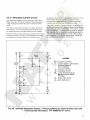
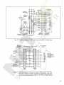
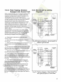
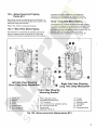
4.2.1-Alternate Control Circuit
Later production breakers use the electrical control circuit
shown in Fig. 3B. This circuit is similar to the circuit shown
in Fig. 3A except that the X-relay and 'F' switch are eliminated.
The motor is energized through the 'G' switch and the Wrelay contact. The 'G' switch deenergizes the motor when
the closing springs are charged and the prop is engaged.
With the closing spring propped fUlly-charged, the breaker
is ready for closing. This may be accomplished electrically
by depressing the closing switch on the breaker (if so
equipped) or by a remote closing switch. Operation of the
closing switch energizes the W-relay, which in turn
energizes the closing solenoid. This removes the prop,
releasing the closing springs to close the breaker.
If the closing switch is maintained closed, the anti-pump relay will remain picked-up to prevent a second motor charge
and closing operation on the breaker in the event it is tripped
open automatically. The closing impulse must be released
and reapplied after the closing springs are fully-charged before a second closing operation can occur. The charging
time is typically 1 to 3 seconds depending on voltage and
the maximum time permitted is 5 seconds.
REMOTE
CLOSE
0-------0- -
t~
CONTROL
SOURCE
-1 ~ -..,
LEGEND
)...
CC -
G-
PB
L-
W
CLOSING SOLENOID
CUTOFF SWITCH. OPEN WHEN
CLOSING SPRING IS
FULLY CHARGED.
AUXILIARY SWITCH
M - CHARGING MOTOR
PB - CLOSE PUSHBUTTON ON
BREAKER ESCUTCHEON,
OPTIONAL.
TC ....... SHUNT TRIP DEVICE
L
CC
W-
w
ANTI-PUMP RELAY
TC
Fig. 38. Alternate elementary diagram. Contact positions are shown breaker open and
closing springs discharged. TYP #5688736 "8" series.
11
SECTION 4-Breaker Operation
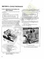
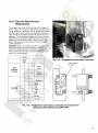
4.3-Connections
4.3.1-Stationary Breaker
In all electrical connections good joint conductivity is a
must. When making power connections to stationary
breakers, the mating joint surfaces must be clean and have
a smooth finish. They should be parallel and firmly bolted
or clamped together. In addition, the bus or cable
conductors must have ample ampacity to prevent
overheat ing.
Control connections to stationary breakers are made to a
terminal board mounted on the breaker. Figure 4 shows
typical closing and tripping connections. If equipped with
an overcurrent trip device which includes a ground fault
element for use on 4-wire circuits, an additional terminal
board is provided on the breaker for connecting to the
equipment-mounted neutral sensor (physically located in
the neutral conductor).
The outgoing connections to breaker accessories and
control devices must be in accordance with the specific
wiring diagram applicable to that breaker.
4.3.2-Drawout Breaker
On drawout breakers the control circuits terminate in the
breaker compartment on the stationary portion of
separable secondary disconnects - see fig. 5.
Q d 9
TERMINAL BOARD
MOUNTED ON FRONT
OF BREAKER AT
UPPER LEFT
2
3
0 o
4
5
0
0
0
0
0
6
7
8
9
10
TO AUX. SW
"a" CONTACT
CUSTOMER
CONNECTIONS
"-t---'
UV
TRIP
SOURCE
'-.,-'
'-.,-'
CLOSING
SOURCE
TRIP
SOURCE
1-)
1+)
REVERSE
CURRENT
DEVICE
POTENTIAL
SOURCE
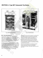
Fig. 4. Control connections to stationary breakers-front view
IYI
IY)}
TRIP
SOURCE
FUSE
{
(X)~
CLOSING
SOURCE
IX)
TRIP
765432
1
/\/\/\/\/\/\/\
/\ /\ /\ /\ /\ /\ /\
765432
765432
STATIONARY SECONDARY DISCONNECT BLOCKS
LOCATED AT TOP OF COMPARTMENT POSITIONS BAND C FURNISHED
ONLY WHEN-REQUIRED
Fig. 5. Control connections to drawout breakers 12
J
front view of breaker compartment
4.4-Tripping
In the closed position, the breaker movable contacts are
held in by a toggle linkage, The breaker is tripped open by
displacing a mechanism latch which allows this toggle
linkage to collapse, The trip latch is rigidly fastened to a
horizontal trip shaft running from left to right through the
breaker, In turn, the trip shaft carries paddles actuated by
the manual trip button and the various other trip devicesovercurrent, reverse current, shunt trip, undervoltage,
open fuse lockout. Viewing the breaker from the right,
rotating the trip shaft counterclockwise trips the breaker;
clockwise movement resets the mechanism latch,
In addition to tripping the breaker, some devices hold the
breaker trip free, i.e" prevent the contacts from closing
even though a closing impulse is applied to the
mechanism. Such devices are the undervoltage, bell alarm
and lockout, electric lockout, open fuse lockout, and the
key operated locks.
These devices and the drawout mechanism interlocks must
be in the reset position before the breaker can be closed.
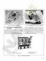
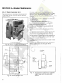
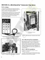
4.5-Charging and Closing Using
the Maintenance Handle
In the absence of control power, an electric breaker can be
closed manually by using the maintenance handle to
charge the closing springs. Referring to Fig. 6:
(a) With the breaker open and springs discharged
release holding pawl slide per instruction label (2).
(b) Install maintenance crank (1) (5686386Gl) to the motor
gear reducer shaft on the front right side of the breaker. Ratchet the maintenance crank up and down until the springs are
fully charged as indicated by the distinct click as the prop is
set. This prevents any further charging of the closing springs.
After the prop is set do not apply undue force to the
maintenance handle.
(c) Depress the "Spring Discharge" lever (3) located
under the horizontal su pport on the front frame. The
springs should discharge and if the latch is properly reset,
the breaker will close. Some style breakers, because of an
interlock in the SWitchgear, can not be manually closed in
the fully engaged position.
(d) Open the breaker by pushing the trip button (4).
1.
2.
3.
4.
Maintenance crank
Instruction label
Spring discharge lever
Trip button
Fig. 6. Maintenance handle charging
13
SECTION 5-Contact Maintenance
Contact Maintenance
5.1.1-Electrical Breaker
Breakers subjected to frequent interruption of high
currents may eventually require replacement of their
contacts. The general rule for determining need of
replacement is the loss of one-half or more of the mass of
the contact tip material. Roughening or light pitting of the
contact surface does not indicate loss of ability to carry or
interru pt cu rrent.
Referring to Fig. 7:
For proper operation of the breaker, the contact structures
must be correctly adjusted. Various interrelated
adjustment parameters are involved. Specific amount of
contact pressure and wipe must exist between moveable
and stationary contacts, The arcing, intermediate and main
contact assemblies must engage and disengage in a
prescribed sequence; and with breaker open, an adequate
gap must exist between the movable and stationary arcing
contacts.
a. Attach maintenance handle (1) and charge the
closing springs until the crank roller contacts prop (4).
b. Insert safety pins (3) into the holes in the guide rods
(2).
c. Release the prop by depressing closing lever (5). The
safety pin now takes the full force of the spring and
restrains it. Now free from spring influence, the breaker
contacts can be inspected and moved at will to the fully
closed position by means of the maintenance handle.
5.1.2-M anual Breaker
a. Operate the breaker closing handle through 3%
complete movements to charge the closing springs.
b. I nsert the safety pins into the gUide rods.
5.1-Slow Closing the Breaker
To perform contact maintenance work the breaker
operating mechanism must be "slow-closed", i.e. manually
driven and controlled at will instead of in the high-speed
manner produced by spring discharge. Slow closing is
achieved by preventing the closing springs from acting on
the mechanism. The breaker is arranged for slow closing
by manually charging the springs and then securing them
in this compressed state by inserting a restraining "safety
pin" see Fig. 7.
Following the inspection period,
a. Recharge the closing springs.
b. Remove the safety pins from the guide rods, return
them to thei r storage clips.
14
c. Continue to operate the closing handle (4th
downstroke) until the spring crank goes over center,
applying full spring force to the safety pin. Closing motion
now can be continued and is completely controlled by the
breaker closing handle.
WARNING: DO NOT APPLY CONTROL
VOLTAGE OR RACK THE BREAKER INTO
THE TEST OR CONNECTED POSITIONS
WHILE THE SAFETY PINS ARE IN USE.
1.
2.
3.
4.
5.
Maintenance
Guide rods
Safety pins
Prop
Closing springs
Fig. 7. Installation of safety pin
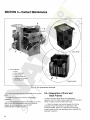
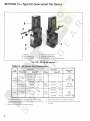
5.2-Arc Quencher Removal and
Inspection
The arc quenchers should be inspected at the regular inspection period. If item 1 is eroded to .125 of an inch from
original conture or item 2 is cracked, Fig. 8, the arc quencher
should be replaced.
5.2.1-Removal and Replacement
Referring to Fig. 8:
a. Be sure breaker is open.
b. Loosen nuts (4) and remove the two slotted head jack
screws.
c. Remove two hex head bolts (5) that mount channelshaped retaining bar to side support (6).
d. Remove channel-shaped retaining bar.
(Continued next page)
15
SECTION 5-Contact Maintenance
1., 2. & 3.
4.
5.
6.
7.
Barriers
Nuts
Hex head bolts
Side support
Protective, barrier
B. Phase barrier screws
9. Mounting bolts
Original design
Fig. 8. Arc quencher removal
e. Lift arc quenchers clear of the movable arcing contact
arms.
f. Inspect arc quenchers carefully and replace if
necessary.
g. During replacement, tighten jack screw nuts (4) first,
then the two hex head bolts that secure the channelshaped retaining bar to side sheet. DO NOT
OVERTIGHTEN THESE TWO SOLTS.
16
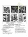
5.3-Separation of Front and
Back Frames
In order to perform some repair and replacement
operation, the front frame must be separated from the back
frame. Proceed as follows: referring to Fig. 9.
a. Open the breaker, manually compress the closing
springs and insert the safety pin as described under
SLOW CLOSING, Section 5.1. Restraining the springs
properly positions the main operating cam to facilitate the
separation operation.
~-
E11]-
1. Opening springs
2. Clevis pin
3. Front/back frame
connector
4. Flux shifter actuator bracket
5. Auxiliary switch
operating rod
6. Phase barriers
7. Side support bolts
8. Position interlock
9. Arc quencher retainer bolts
Fig. 9. Front and back frame separation details
b. Remove the two opening springs (1) (on lower part of
the breaker) from the outside pole units.
c. Remove the clevis pin (2) from the center pole unit.
d. Disconnect the programmer CT wire harness at each CT
and remove any tye wraps holding leads to back frame.
e. Disconnect the flux shifter actuator bracket from the
crossbar assembly (4).
f. Remove the auxiliary switch operating rod (5).
g. Remove outside phase barriers (6).
h. Remove side support bolts (7).
i. Remove position interlock on AKD, AKD 5. AKD
6 type (8).
j.
k. Remove the six nuts from the back frame using a
socket wrench with an extension. These include the two
nuts at the top of the frame.
I. Check along the trip shaft for a mechanical
interference or connection between the overcurrent trip
device and the trip paddles. Remove mechanical
connection if present, or if interference exists, use extreme
care when removing or reassembling front and back
frames to avoid mechanical breakage of trip devices.
When reassembling the front and back frames, both should
be positioned vertically so that the trip shaft is horizontally
aligned. It is recommended that the breaker back frame
be fastened to a suitable mounting surface so that the front
frame can be supported by a sling or hook as the bolts are
being installed.
Remove arc quencher retainer and bolts (9).
17
SECTION 5-Contact Maintenance
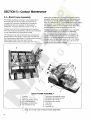
5.4-Back Frame Assembly
The breaker backframe consists of a frame assembly to
which the pole units are mounted. Each pole unit is
connected to a common crossbar which provides for
simultaneous pole unit operation by the breakers
mechanism. A typical backframe is shown in Fig. 10.
Mating with the stationary contacts is a moveable contact
assembly consisting of multiple main and intermediate contact fingers (10) and (8). These moveable contact fingers
pivot on a stationary pin (11), which fasten them to the lower
contact block. The insulated link (13) which is attached to
the breaker crossbar (1) and moveable contact assembly
gives the open and close motion to the contact arm.
The pole units consist of a molded base which supports
the line and load stud assemblies, stationary and moveable
contact assemblies and the actuating linkage.
The stationary arcing contact assembly (3) is a separate
set of contact fingers, pins, springs and pivot block.
The stationary main contact assembly (9) comprises of a
spring loaded contact fingers. Interlocked with these are
the intermediate contact fingers (7) whose contact surface
project beyond that of the mai n such that the
intermediates make before, and break after the mains.
The moveable arcing contact assembly (5) consists of
multiple contact arms carried on two moveable pins (6)
and (12). The arcing contact arms interleave the main
contacts and pivot with them about pin (6). This relative
motion is obtained by the insulating links (13) from the
contact arms to the breaker crossbar.
BACK FRAME ASSEMBLY
1.
2.
3.
4.
5.
6.
Crossbar
Pole unit
Stationary arcing contact
Pin-stationary arcing
Moveable arcing contact
Pin-moveable arcing
7.
8.
9.
10.
11.
12.
13.
Stationary intermediate contact
Moveable intermediate contact
Stationary main contact
Moveable main contact
Pivot pins
Drive pins
Insulated link
Fig. 10. Front view of back frame assembly
18
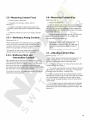
5.5-Measuring Contact Force
a. Remove the arc quenchers.
b. Separate front and back frames, refer to
Section 5.3
c. Inspect all contacts for wear and arc erosion and,
if necessary, replace (see criteria for replacement, Section
5.10)
d. Measure contact force only if you replace contact
arms.
5.5.1-Stationary Arcing Contacts
5.6-Measuring Contact Wipe
Referring to Fig.11:
a. Remove arc quenchers.
b. With the breaker open measure the horizontal distance
from the edge of the stationary arcing contact to the retainer
("A" dim.); for main and intermediate contacts measure the
horizontal distance from the top of the cont act to the contact
arm retainer ("8" dim.).
c. Close the breaker and repeat step b. The difference
between the readings determines the contact wipe.
See Table 6 for correct readings.
Referring to Fig. 11:
Place a push scale on the stationary arcing contact at a
poi nt 1-3/16 from the contact pivot and depress that
contact 1/4 of an inch. Load on the scale should read
within the range listed in Table 6, column 8.
If the load is not within the range listed in column 8,
replace the spring under that contact assembly.
5.5.2-Stationary Main and
Intermediate Contacts
Place a push scale on the stationary contact at a point 27/8 from the contact pivot and depress that contact to the
wipe dimension shown in Table 6, column 3 for the mains
and column 6 for the intermediates. Load on the scale
should read within the range listed in Table 6, column 2 for
the mains and column 5 for the intermediates.
If the load is not within the range listed replace the spring
under that contact assembly.
CAUTION: FOR SAFETY REASONS BE
EXTREMELY CAREFUL NOT TO TRIP THE
BREAKER WHEN MEASURING CONTACT
WIPE.
5.7-Adjusting Contact Wipe
Referring to Fig. 11:
a. To obtain proper contact wipe and pressure on the
center pole, dimension "C" should be increased to
increase wipe and decreased to decrease wipe.
b. To change dimension "COO remove the clevis pin and
rotate the clevis as necessary.
c. To prevent overstressing the clevis threads dimension
"COO should not exceed 3/16 in. and space "COO should be
filled with shims to 0.005 in. of being solid. "
d. With the proper center pole wipe obtained, moving
the crossbar adjusti ng plate on the center pole to the right
will simultaneously increase the wipe on both outside
poles; moving the adjusting plate to the left will have the
reverse effect.
e. To increase the wipe on either outside pole, individually
move the crossbar adjusting plate of that pole to the left; to
decrease the wipe move the adjusting plate to the right. See
Section 5.11.
19
SECTION 5-Contact Maintenance
/
Open gap
2'12 to 2314
Clevis
(centerpole)
A_.v--+~
Stationary
Arcing Contact
UPPER
STUD
Lower
Stud
Stationary main contact
Fig. 11. Measuring contact force
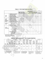
Table 6
Arcing Contacts
Intermediate Contacts
Main Contacts
Column
1
2
3
4
5
6
7
8
Breaker
Type
Oty.
Per
Pole
Force
in
Lbs.
Wipe
in
Inches
(B)
Oty.
Per
Pole
Force
in
Lbs.
Wipe
in
Inches
(B)
Oty.
Per
Pole
Force
in
Lbs.
3
35-55
1
1
1
1
2
35-55
2
3
3
5
5
31-43
AKS-50 (AC)
AKS-!iO 10C;\
AKR-75 (AC)
AKR-75 (DC)
AKR-100 (AC/DC)
~
5
5
6
25-55
'/'6 to
'/64
25-55
··
··
·
'The intermediate contact wipe should be at least '/16 in. greater than main contact wipe.
20
9
Wipe
In
Inches
(A)
5/32 to
9/32
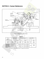
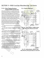
5.B-Measuring Contact Open Gap
Prior to measuring the open gap verify that the cross arm
buffer assemblies, refer to Fig. 12, are touching. The stackup dimension of each buffer should be within .015" of each
other. Adjust to this dimension by adding or removing washers.
Measure the contact open gap between the movable and
stationary contacts as shown in Fig. 13. This distance
should be between 2-1/2" to 2-3/4". This gap may be
adjusted by repositioning shims on crossbar assembly.
The locking nuts on the buffer bolts should be locked in
such a position that the buffer bolt may be rotated freely.
1-B uffer stop
2-Buffer washers
3-Buffer shims
4-Lock nuts
~
iF
Fig. 12. Buffer assembly
Fig. 13. Measuring contact open gap
21
SECTION 5-Contact Maintenance
5.9-Checking Contact Sequence
5.10-Replacement of Contacts
On the horizontal plane, the difference in the making of the
arci ng contacts on the same pole must be no greater than
1/16 in.; this difference between arcing contacts on
separate poles must be 1/16 in. If it is desired to advance
or retard the closing of the main contacts of a pole, loosen
the bolts holding the adjustment plate, refer to Fig. 21, of
that pole and slide plate to the left to advance contact
closing, or to the right to retard contact closing. Make this
adjustment on the outer poles, using the center pole as a
reference. Upon retightening adjustment plate bolts, make
sure the locking tabs are turned up around bolt heads,
locking the bolts securely in place.
Criteria for replacement:
Contact sequence in the vertical plane should be such that
when the arcing contacts are just touching, the
intermediate contact gap should be at least 3/16 in. and
the main contacts gap at least 1/4 in., see Fig. 14.
a. Arcing contacts should be replaced when eroded to a
thickness of 5/64.
b. Intermediate contacts should be replaced when flush
with main contacts (.062 lead when new).
c. Main contact very seldom needs replacement.
Replace when arcing contacts have been neglected
causing severe erosion of mains so you can not obtain
proper contact depression.
When replacing the arcing contact assemblies you do not
have to separate the front frame from the back frame.
5.1 O.1-Stationary Arcing Contacts
a. Refer to Fig. 15.
b. Remove insulator block (1).
NOTE: This check can best be made by means
of the maintenance handle, with the safety pin
restraining the closing springs. See Section 5.1
for this procedure.
c. Slide pin (2) to side. Contact assembly (3) will lift
freely exposing two springs (4) and button (5) ..
d. Install new parts inreverse order.
5.10.2-Movable Arcing Contacts
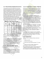
If the gap is under the required minimum, it is usually possible to form the arcing contacts and obtain the required dimensions. To form the contacts, place a piece of conduit
approximately two feet long, over the contact and form the
contact either forward or backward by bending it. If the
proper dimensions are still not obtained, the moveable arcing contacts should be replaced.
These contact arms should be replaced whenever the stationary arcing contacts are replaced.
a. Refer to Fig. 15.
b. Remove retaining rings (6). Slide pins to side and
withdraw the contact arms.
If it has been necessary to make any adjustments while
obtaining proper contact sequence, the contact wipe must
be checked, and adjusted, if necessary, see Section 5.6.
1. Insulator block
2. Pin
3. Contact assembly
Fig. 14. Measuring main contact gap
4. Springs
5. Button
6. Retaining rings
Fig. 15. Replacement of stationary and
movable arcing contacts
5.10.3-Moveable Main and
Intermediate Contacts
d. Remove contact arms, noting two spring washers (9)
on each contact pivot.
a. Refer to Fig. 16.
b. Loosen crossbar bolts so link (10) can move freely.
c. Remove retaining rings (7) from pins (8).
Slide pins (8) until contact arms can be withdrawn.
Upon re-assembly, position two spring washers into
counter bore on one side of contact arm (9). Note left and
right hand orientation of contact arms and position of
intermediate contact.
e. Before tightening crossbar see assembly and
adjustment of crossbar, Section 5.11.
iE----
7.
8.
9.
10.
11.
Retaining rings
Pins
Spring washers
Crossbar bolts
Intermediate contact
Fig. 16. Replacement of main and intermediate contacts
23
SECTION 5-Contact Maintenance
5.10.4-Stationary Intermediate and
Main Contacts
a. Separate the front frame from the back frame. Refer
to Section 5.3.
b. Remove crossbar.
NOTE:ln the steps below, refer to Fig. 17 to
identify the numbers in the parenthesis.
c. Remove arcing contact block (3) by removing allen
screws (4) and (5).
d. Depress main and intermediate contacts as shown in
Fig. 18 to relieve spring pressure on contact stop bracket
(6) before removing mounting screws. On AKR100 you
must remove the outside moveable contact arm before
trying to remove contact stop bracket mounting screws.
e. Remove retaining ring (7) and slide pin (8) to side and
withdraw the contact arm. Fig. 17.
f. Remove contact, noting two spring washers on each
contact pivot. Upon re-assembly, position two spring
washers into counter bore on one side of contact arm. Fig.
19.
NOTE: Left and righthand orientation of
contact arms and position of intermediate
contact. Fig. 19.
g. Depress main and intermediate contacts to relieve
spring pressure on contact stop bracket before starting
screws. Tighten screws before releasing pressure.
Fig. 18.
h. Re-install arcing contact block by holding arcing
contacts depressed (Fig. 20) while tightening screws.
i. Assemble crossbar.
j. Always check contact wipe following contact
replacement. See Secton 5.6.
ill
1.
2.
3.
4.
5.
6.
7.
8.
Main contact arm
I ntermediate contact arm
Arcing contact block
Arcing contact
Allen screws
Contact stop bracket
Retaining ring
Pivot pin
Fig. 17. Intermediate and main contactsassembly details
24
6. Contact stop bracket
Fig. 18. Relieving spring pressure
Fig. 19. Upper stud details
5.11-Assembly and Adjustment of
Crossbar
When assembling crossbar to back frame push moveable
arcing contacts forward until they touch stationary arcing
contacts on upper terminal. Then lay crossbar on top of
links on pole units. Assemble adjusting plates as shown
making sure slots in plates are properly oriented. Fasten
1. Crossbar
2. Stationary arcing contacts
Fig. 20. Re-assembly of arcing contacts
screws with locking plates on crossbar finger tight and set
crossbar to dimension shown making sure that all three
poles of moveable arcing contacts are touching stationary
arcing contacts within .032. Tighten screws as shown first
"A", second "B", and finally "C" to 400 inch pounds. Bend
tabs on locking plates to secure screws. Refer to Fig. 21.
After assembling crossbar always check contact wipe and
open gap, see Sections 5.6 thru 5.8.
3. Moveable arcing contacts
4. Adjustment plates
Fig. 21. Crossbar assembly
25
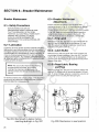
SECTION 6-Breaker Maintenance
Breaker Maintenance
6.3-Breaker Mechanism
Adjustments
6.1-Safety Precautions
Electric and Manual breakers have the same basic
mechanism shown in Fig. 22. All the adjustments detailed
below must be made with the breaker in the upright
position and the mechanism in the reset position as shown
in Fig. 22B. Reset the mechanism by manual operation
using the slow close method given in Section 5.1. The
roller (15) must be clear of the cam (2), see Fig. 22C.
BEFORE INSPECTION OR ANY
MAINTENANCE WORK IS DONE BE SURE
THAT THE BREAKER IS IN THE OPEN
POSITION. ALL ELECTRICAL POWER, BOTH
PRIMARY AND CONTROL SOURCES,
SHOULD ALSO BE DISCONNECTED.
ENSURE THAT THE CLOSING SPRINGS ARE
DISCHARGED.
6.2-Lubrication
In general, the circuit breaker requires moderate lubrication.
Bearing points and sliding surfaces should be lubricated at
the regular inspection periods with a thin film of GE Lubricant
050HD38 (D6A15A1 Mobilgrease 28). Before lubricating, remove any hardened grease and dirt from latch and bearing
surfaces with kerosene. ALL EXCESS LUBRICANT SHOULD
BE REMOVED WITH A CLEAN CLOTH TO AVOID ACCUMULATION OF DIRT OR DUST.
NOTE: The use of cotton waste to wipe bearing
surfaces should be avoided, as the cotton
ravelings may become entangled under the
bearing surfaces and destroy the surface of the
bearing.
6.3.1-Trip Latch
Referring to Figs. 22C, 220 & 23, the gap between the trip
latch (10) and the roller (9) should be between .015 and
.032. This adjustment can be obtained by loosening nut
(19) and turning allen screw (6).
6.3.2-Latch Buffer
Referring to Fig. 220, the center line of the trip latch (10)
should pass through the center of the roller (9). The latch
buffer (18) on the mechanism frame can be adjusted by
loosening the retaining screws to reposition the latch with
respect to the roller.
6.3.3-Reset Latch, Bearing
and Prop
Referring to Figs. 22C, 220 & 24, the distance between the
bearing (17) and the prop (5) should be between .015 and
.032. To obtain this gap, advance or retard the nuts (4A) on
the bottom of the rod using the reset spring (4).
On drawout breakers the contact surface of the disconnect
studs should be cleaned and greased with GE Lubricant
D50H 038 (D6A15A1 Mobilgrease 28).
Fig. 22A. Mechanism in motion before
resetting as shown in Fig. 22C
26
Fig. 228. Mechanism in reset position
7----iE
ill]
I
11~----iE
iJ'
[II
~--It-I~
~
-ml
d
>'-~J--~
II
i-
Q---rlJ
\\~,~:---a
---1
.4t=====,;m
~
1.
2.
3.
4.
4A.
5.
6.
7.
8.
9.
~
Spring
Cam
Link
Reset spring
Spring adjusting nuts
Prop
Adjusting screw
Adjusting screw stop pin
Prop return spring
Roller
Fig. 22C. Mechanism in closed position
(closing spring discharged)
10.
11.
12.
13.
14.
15.
16.
17.
18.
19.
Trip latch
Trip shaft
Clevis pin
Clevis
Reset latch
Roller
Prop
Bearing
Buffer
Nut
Fig. 220. Latch, bearing, and prop
-il
-il
-~
-~
-~
-f]
1. Feeler gage
2. Trip latch
3. Roller
Fig. 23. Adjusting trip latch and roller
1. Feeler gage
2. Prop
3. Bearing
Fig. 24. Adjusting bearing and prop
27
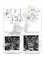
SECTION 6-Breaker Maintenance
6.4-Electrical Mechanism
6.4.1-Control Components
The function of the electrical mechanism is to charge and
discharge the closing springs either electrically or
manually. The electrical mechanism consists of
Referring to Fig. 25:
a. Control components
b. Charging motor
c. Motor operator unit
d. Spring discharge interlock
Section 4.2 details the associated control circuitry for the
electrical mechanism.
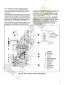
The control relay (X) is located on the left side of the front
frame channel. It may be removed by disconnecting the
wiring, loosening the two mounting screws and lifting it
slightly to pass the top mounting screw through the
keyhole mounting. The entire relay should be replaced
rather than changing coils and contacts.
The antipump relay (W) is located on the left side of the
front channel. The connections to this relay are soldered.
Relay replacement requires unsoldering of these
connections and removing the mounting hardware. When
replacing relay take care in soldering connections. Do not
use excess amount of solder on connectors as to impair
operation of contact arms.
The closing solenoid is located in the lower right hand side
of the motor operator unit. The switchette is separately
mounted in front of the solenoid.
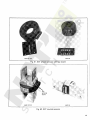
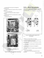
1. Terminal board
2. Auxiliary switch
3. F&G switches
4. Motor
5. Anti-pump relay (W)
6. Control relay (X)
7. Closing button
8. Switchette
9. Closing solenoid
Fig. 25. Control component location
28
After replacing closing solenoid or switchette check
adjustment of switchette and readjust if necessary. With
breaker in discharge position use a .010 feeler gage and
push closing solenoid to position shown in Fig. 26.
Switchette must be activated at this point. To adjust loosen
switchette mounting screws and pivot switch until
activated, then tighten screws. Recheck.
~
MOlor
AHembly
OPERATOR
Mounting
Hrmiwr.tre
MOTOR
Closing Solenoid
mounting
Hardware
//~
Maintenance
Handle Shall
,
W
.0'_.060,men","
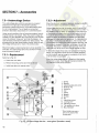
required with
lever in posilion
shown Adjust
II necessary
'----='l'+.IIF:1Io-""""~Retaining Ring
Drille Link
Opening Spring
Bracket
Opt>fd!,ng leyer
Fig. 27. Electrical mechanism
Connection
Points
"0"
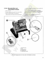
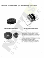
Fig. 26. Switchette adjustment
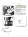
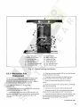
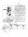
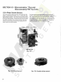
6.4.2-Charging Motor
The charging motor is located on the right side of the
breaker. It is mounted on the motor operator as shown in
Fig. 27. A driving pawl is mounted eccentrically on the
motor shaft, see Fig. 28. As the motor turns, the driving
pawl rotates the ratchet which charges the closing springs.
The ratchet is kept from reversing its direction by the
holding pawl. To remove the motor:
-iJ
a. On AKS 50 you must remove the side sheet.
b. Disconnect and identify the motor leads at the closing
solenoid and cutoff switch.
c. Remove three motor mounting screws.
d. Remove motor.
e. When reassembling, assemble with the driving pawl
pointing toward the front of the breaker.
See Fig. 28.
1. Driving pawl
Fig. 28. Motor removal
29
SECTION 6-Breaker Maintenance
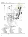
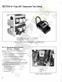
6.4.3-Motor Operator Unit
The motor operator unit is located on the right hand side
of the breaker as shown in Fig. 29. Operator details are
shown in Fig. 30.
The motor drives the crank roller/maintenance handle
shaft until the control circuitry stops the motor and roller is
against the prop. The crank roller drives the cam shaft,
charging the spring, through the cam shaft paddle,
see Fig. 31.
The motor operator unit is not adjustable. To replace the
unit, refer to Fig. 27:
a. Slow close the breaker, see Section 5.1
b. Remove the motor, see Section 6.4.2. The motor
wiring doesn't have to be disconnected.
c. Disconnect the wiring to the closing solenoid and
solenoid switch.
d. Remove retaining ring from closing solenoid drive
link.
e. Remove three mounting bolts, one from the side, two
from the bottom of the charging mechanism. Note the
positions of the standoffs on the two bottom mounting
bolts and replace in the same position when reassembling.
f. Rotate motor operator shaft so its crank roller faces
the rear of the breaker. Refer to Fig. 32.
g. Slide spring charging mechanism out toward the right
of the breaker.
1. Motor operator unit
Fig. 29. Motor operator unit location
1)= ===rl -
Cam
Shaft Pivot
II
II
I'
"
h. Install new spring charging mechanism making sure
the crank roller engages cam shaft guide. Refer to
Figs. 31 and 33.
- - -
Celm Shaft
~'II
:I
____ l'==:=:J,L----
Paddle
Crank
Roller
Maintenance
Handle Shaft
Motor
Operator
Crank
Roller
.
Guide
Assembly
r"T-t--_
Fig. 30. Motor operator unit
30
era n k
Roller
Fig. 31. Engagement of the motor operator
crank roller with the cam shaft
paddle
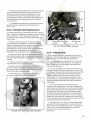
i.
Reassemble all components and connect all wires.
j. Remove safety pin from closing spring by placing
your maintenance handle on the shaft which extends from
the spring charging mechanism and charge the closing
spring until the charging mechanism roller engages with
tile prop. Remove safety pin. This must be done before
power is applied to motor.
k. Operate the breaker using the maintenance handle
and spring discharge mechanism a few times. Verify that
the breaker is operati ng properly.
I. Before applying control voltage to your breaker verify
that the motor cut off switches are properly adjusted.
Charge the closing spring as described in
step j. (roller resting on prop). Adjust the motor cut off
switches, shown in Fig. 35, so that they are depressed to
the point where the main stem of each switch is located
.005" to .031" from the threaded barrel, see Fig. 34.
(Continued next page)
Fig. 32. Motor operator removal
______
.031
.005
-4---
Main Stem
Threaded Barrel
Fig. 34. Motor cutoff switch adjustment
1. Cam shaft paddle
2. Guide
Fig. 33. Cam shaft lever and guide
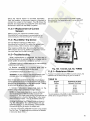
31
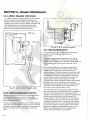
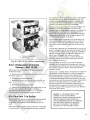
SECTION 6-Breaker Maintenance
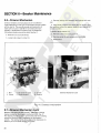
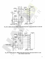
6.4.3-Motor Operator Unit (Cont.)
m. When the control voltage is applied to your breaker,
the motor operator will be energized and charge the
closing spring. The G switch (see Fig. 36) of the motor cut
off switch unit will stop the motor operator just before the
roller engages the prop. The breaker may be closed
manually by depressing the spring discharge lever or
electrically by energizing the closing solenoid.
Right Side
Center Channel
Control Voltage
Nameplate
"G" Switch
"F" Switch
Fig. 36. F & G switch location
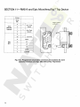
6.S-Manual Mechanism
_ .l!
The stored-energy operating mechanism of a manual
breaker consists basically of a closing spring assembly,
ratchet wheel and output crank assembly, handle shaft and
pawl assembly, and the escutcheon-mounted closing
handle.
Spacer
Paddle - - - ' f - ; ; I
Fig. 35. Motor cutoff switch unit
6.4.4-Spring Discharge Interlock
Referring to Figs. 27 & 30, the spring is discharged when
the prop is pulled out from the roller. This is done
electrically by the closing solenoid and manually by the
spring discharge interlock.
The spring discharge interlock drive link must be adjusted
to the .03 to .06 inch dimension shown in Fig. 27. This gap
provides the closing solenoid linkage the initial freedom it
requires to develop the force necessary to remove the
prop.
32
The manual AKR breaker is equipped with the springcharged, stored-energy mechanism shown in
Figs. 37 & 38.
The closing springs (5) are charged by operating the
manual closing handle (22) on the front of the breaker,
instead of the closing motor as is the case with the
electrical breaker. Closing this breaker is accomplished by
pumping the operating handle four complete cycles, first
counterclockwise through 120 degrees from its normal
vertical position and then clockwise back through 120
degrees from its normal vertical position and then
clockwise back through 120 degrees. When approximately
70 degrees of the fourth clockwise stroke have been
completed, the closing springs, which have been charged
during the previous strokes to the closing handle, are
driven over-center and the breaker closes.
The first stroke of the closing handle causes the ratchet
pawls (21) attached to the handle shaft (23), to engage the
first tooth of the ratchet wheel (17), thus beginning to
charge the closing springs. The subsequent closing handle
strokes perform the same fu nction as the pawls (21)
engage the teeth in the ratchet wheel (17), thus rotating
the ratchet wheel and output crank (32) and completely
charging the closing springs. This rotation of the ratchet
wheel and output crank is in a countercloskwise direction
from the lower position, through slightly more than 180
degrees, to a position just beyond dead center. In this
position the closing springs are free to release their
energy, closing the breaker at a high speed.
1.
3.
5.
7.
18.
19.
20.
Upper spring pin
Safety pin and chain
Closing springs
Pawl springs
side plate shims
Side plate mounting bolts
Bearing side plate
21.
25.
26.
27.
31.
33.
34.
Ratchet pawls
Main closing crank
Pawl buffer stop
Buffer stop shims
Lower spring pin
Ant. rebound spring
Ant. rebound pawl
Fig. 37. Manual closing mechanism
6.5.1-Mechanism Part
Replacement
If it is necessary to replace any of the mechanism parts,
the following total procedure is recommended. This
procedure may be halted at the step required to replace
any particular part. Referring to Figs. 37 & 38:
a. Install the safety pin (3) as described in
Section 5.1.2.
b. Remove the closing spring assembly by removing the
upper and lower spring pins (1,31).
c. Remove the right hand bearing side plate (20), and
the side plate shims (18) by removing four mounting bolts
(19), thus allowing the main closing crank (25) to be
removed.
d. Remove the closing handle (22) by removing two set
screws threaded in same hole.
e. Remove the front escutcheon by removing four
screws holding it to the front frame center support.
f. Remove handle shaft extension by removing
roll pin.
g. Remove the handle return spring (29) by unhooking
either end of the spring.
h. Disconnect the top end of each pawl spring (7).
i. Remove the roll pin (24), thus allowing the closing
handle shaft and pawl assembly (23) to be removed.
j. Remove the ratchet wheel (17) and its assembly (16)
by removing self locking screw (15) and thrust bearing
(12). If shims (13) are present they must also
be removed.
(Continued next page)
33
SECTION 6-Breaker Maintenance
MANUAL MECHANISM
- - - - - - - - - - -I---."...-~-::;;i
~.
!
3 4------~_+-lD\-____L
~~~~y;--ti--5-------++;~
I
1E--+-+-++-t+----6---------+,---';--t--'R\
!Oi£-+----7
i i\II
! !III
I
I
!
I
;
"
I
II
§D
31
-r-jH
.'
(\(),
'
28
il
!i
-,r~·-
Ji
Partial Front View
With Handle And Escutcheon Removed
1,
2.
3.
4.
5.
6.
7.
8.
9.
10.
11.
Upper Spring Pin
Safety Pin Holder
Safety Pin and Chain
Safety Pin Hole
Closing Springs
Guide Rod
Pawl Springs
Front Escutcheon
Front Bearing Plate
Bearing Plate Mounting Bolts
Output Crank Roller
12. Thrust Bearing
13. Shims
14. Groove Pin
15. Nylok Screw
16. Ratchet Wheel Shaft and Asm.
17. Ratchet Wheel
18. Side Plate Shims
19. Side Plate Mounting Bolts
20. Bearing Side Plate
. 21. Ratchet Pawls
22. Manual Closing Handle
23. Closing Handle Shaft and Pawl Asm.
\ '
I
\ !~ I
'..
-~jJ
!
j
24.
25.
26.
27.
28.
29.
30.
31.
32.
33.
34.
Roll Pin
Main Closing Crank
Pawl Buffer Stop
Buffer Stop Shims
Buffer Stop Support
Handle Return Spring
Mechanism Roller
Lower Spring Pin
Output Crank
Ant. Rebound Spring
Ant. Rebound Pawl
Fig. 38. Manual closing mechanism charged position
34
k. Remove front bearing plate (9) by removing mounting
bolts (10) accessible from the front of the breaker. The
mechanism is now completely disassembled. It is not
recommended that any of the subassemblies removed
during the above operation be further disassembled in the
field. Replacement sub-assemblies should be obtained
from the factory.
I. To reassemble the mechanism, reverse the procedure
described above and follow the adjustments given in
Section 6.5.3.
6.5.2-Ratchet Pawl Replacement
The manual mechanism is inoperable with broken ratchet
pawls. Therefore, the safety pin probably can't be inserted
into the gUide rod. If this is the case, the following
procedure is used to replace the ratchet pawls. Refer to
Figs. 37 & 38:
a. Remove upper spring pin (1) by removing retainer
ring and pushing pin through front channel and spring
support. Closing spring will discharge. Remove individual
closing springs. Remove lower spring pin (31) and
remaining part of spring support. When replacing closing
spring assembly, a new assembly is required or
reassembly of the existing parts using a pressing means.
b. Remove the left or right hand bearing side plate (20)
and the side plate shims (18) by removing four mounting
bolts (19), thus allowing the main closing crank (25) to be
removed.
c. Remove anti-rebound pawl (34) by removing retaining
ring (36) shown in Fig. 39 and spring (33).
d. Remove retaining ring (35, Fig. 40). Disconnect
springs (7) remove buffer stop (26). Both pawls can now
be removed. See Fig. 40. When reassembling, verify that
retaining ring (36) is properly seated.
e. After replacing parts and before adding closing
spri ng check adjustments given in Section 6.5.3.
. 7. Disconnect
springs
26. Buffer
stop
35. Retaining
ring
Fig. 40. Ratchet pawl removal
6.5.3-Adjustments
Frequent adjustments to the mechanism should not be
required. If the mechanism has been disassembled, it will
be necessary to check the following adjustments:
1. It may be necessary to add shims (13) to reduce the
end play of the ratchet wheel shaft (16). An end play of
0.010 to 0.020 inch is recommended. Shims should be
obtained from the factory.
2. It may be necessary to add buffer stop shims (27) to
the buffer stop (26) to provide a clearance of 1/64 to 1/32
inch between the pawls (21) and the buffE;H stop, when the
pawls are touching the ratchet wheel teeth extend.ing a
maximum distance from the center of rotation of the
ratchet wheel (17). This measurement should be made
while operating the closing handle during the four spring
charging operations and before the closing springs are
reassembled.
3. The ratchet pawls (21) should operate freely
throughout the closing strokes. They should engage the
ratchet wheel teeth near the end of each cou nterclockwise
and clockwise stroke of the closing handle with a definite
clicking sound, indicating a free non-binding operation.
After the clicking sound is detected, the closing handle
should have a minimum overt ravel of 1/2 in. or 3V2 degrees,
measured at the end of each handle stroke. At the end of
the four stroke the rebound stop (34) must move into place
to properly position the ratchet wheel.
36. Retaining ring
Fig. 39. Anti rebound pawl removal
4. The groove pin (14) in the front of the ratchet wheel
assembly (16) must be assembled in a manner that will
allow screw (15) to be tightened securely. A clearance of
1/64 to 1/32 in. should exist between the front of the
groove pin and the rear surface of the
screw head.
35
SECTION 6-Breaker Maintenance
6.6-Drawout Mechanism
Drawout breakers are manuafactured in five different
styles depending on the type of equipment that the breaker
will be used in. The mounting code and description of
each style is found in GEI-86151 furnished with each
breaker. If replacement of racking cam is needed the
following procedure should be used. See fig. 41.
c. Remove racking cam assembly and replace with new
cam.
d. Align center of worm with worm gear on racking cam
then position collars firm against supports and tighten set
screws in collars.
To replace guide support (4):
a. Remove screws (5) and support (6).
a. Remove nut (1) and screw (2).
b. Remove guide (4) and replace with new guide.
b. Loosen set screws in collar (3).
c. Reassemble.
6
3
4
3
1. Nut
2. Screw
3. Set screw in collar
4. Guide support
5. Screws
6. Support
Drawout Mechanism Lock
Fig. 41. Drawout mechanism
6.7-Drawout Mechanism Lock
Breakers manufactured after January, 1993 have a locking
device installed on the drawout mechanism shaft, Fig. 41.
This device provides a stop to prevent the shaft from rotating
unless the interlock slide is depressed by the drawout
wrench. The racking handle cover plate when depressed, releases a pin on the shaft allowing it to rotate.
36
SECTION 7........ Accessories
7.1-Primary Disconnects
Primary disconnects are found only on drawout breakers.
They provide the flexible connection between the breaker
line and load terminals and the equipment line and load
terminals.
7.1.1-AKR 75/100
There are two types of primary disconnects found on the
AKR 75/100 breakers.
Fig. 42 shows the tubular type primary stud used on
replacement breakers for the older AKD, AKD5, AKD6
sWitchgear. If for any reason the primary stud must be
replaced or removed simply disassemble nut and bolt
arrangement that is crisscrossed through the tubular stud.
When reassembling mounting hardware apply equal amounts of
torque to nuts, so distortion to tubular mounting stud does not
occur. Torque nuts between 250 to 300 in Ibs.
Fig. 43 shows the finger type disconnect assembly used on
AKD-6, AKD-8 switchgear and substructure type breakers.
If replacement of primary finger is needed, you must
replace complete sUbassembly set of fingers, which are
factory adjusted to proper spring tension. Reassemble as
described above. See renewal parts publication GEF-4552
for proper ordering data.
AKR75·
AKR100
Fig. 42. Tubular type disconnects
FINGER-TYPE
PRIMARY
DISCONNECTS
AKR75
AKR100
Fig. 43. Finger type disconnects
37
SECTION 7-Accessories
1.1.2-AKS/AKST 50
The AKS 50 and AKST 50 use eight primary fingers per
phase as shown in Figs. 44 thru 47. Refer to these
illustrations when replacing the disconnects. Note the
following details.
38
Fig. 47-The position of the spacer in the breaker stud.
The hole in the spacer must be positioned as shown so it
will align with the holes in the clip.
Fig. 46-The engagement of the fingers with the retainer.
Also the location of the "bowtie" spacers in the fingers,
both upper and lower.
(Continued next page)
Fig. 44. Primary disconnect assembly
Fig. 45. Partial primary disconnect ASM
Fig. 46. Partial primary disconnect ASM
Fig. 47. Partial primary disconnect ASM
Fig. 44 & 45- The position of the upper and lower retainers
and, again, the 'bowtie' spacers.
The primary disconnect assembly is factory adjusted to apply a
force of 85-105 pounds on a 1/2 thick copper bar inserted
between the upper and lower fingers. After installation of the
disconnect assembly this force range is obtained by tightening
the locknuts to set the dimension shown in Fig. 48. Note that
this dimension is measured between the top of the retainer and
the underside of the washer. Also note that no bar is inserted
between the fingers when setting this dimension.
1. Secondary disconnect
Fig. 49. Secondary disconnects
Fig. 48. Primary finger adjustment
7.2-Secondary Disconnects
The secondary disconnects for all drawout breakers serve
as connections between breaker control circuit elements
and external circuits. They are mounted on a horizontal
cross-channel at the top rear of the breaker as shown in
Fig. 49. These secondary disconnects dllow removal of the
breaker without having to detach external connections.
The moveable part of the secondary disconnects consists
of an insulating body which holds a conducting springloaded plunger to which a flexible lead is attached, see Fig.
50. As the breaker moves into its enclosure, the plunger is
depressed by sliding onto the stationary disconnects of the
enclosure.
1. Body
2. Tip
3. Tube
4. Tabs
Fig. 50. Secondary disconnect details
7.2.1-R eplacement
Replacement of the disconnects is given below. Refer to
Fig. 50:
a. Unfasten disconnect body from breaker
cross-channel.
b. Open tabs which hold wires on inner side.
c. Pull contact tip loose from hollow tube.
d. Remove contact tip by cutting wire at its base.
(Continued next page)
39
SECTION 7-Accessories
7.2.1-(Cont.)
e. Push wire through hollow tube of new disconnect
assembly.
7.3.1-Replacement
f. Strip insulation off end of wire to about '/, in. from the
end.
GE SB-12
a. Disconnect all leads.
Referring to Fig. 51:
g. Place new contact tip on end of wire and crimp.
b. Remove two mounting bolts.
h. Pull wire through hollow tube until contact tip fits
snugly against end of hollow tube.
c. Disengage auxiliary switch shaft (4) from triangular
link (2).
i. Crimp tab on other side of assembly to hold wire in
place.
d. Orient the shaft of the new switch so that the arrow
stamped on the shaft end points towards the front of the
breaker.
j. Any hollow tubes which are not used should be
pushed into the disconnect body and held in that position
by placing fiber spacers over inner ends of tubes and
spreading tabs.
e. Push auxiliary switch shaft into square hole in link
(breaker open).
f. Replace mounting hardware and wiring.
k. When all wires have been connected, refasten the
body of the moveable disconnect assembly to the breaker
cross-channel.
7.3-Auxiliary Switch
7.3.2-Adjustment
All electrically operated breakers and manual breakers having shunt trips are supplied with auxiliary switches. Depending upon the requirements of the breaker application, the
switch may contain two to six stages. Usually each stage
one "A" contact and one "B" contact. "A" contacts are open
or closed as the breaker is opened or closed. "B" contacts
are the reverse of this.
The auxiliary switch is mounted on the upper left side of the
mechanism frame as shown in Fig. 51. As the crossbar (1)
moves to the open or closed position, it operates triangular
link (2) via operating rod (3). The triangular link rotates the
auxiliary switch operating shaft.
1. Crossbar
2. Triangular link
3. Operating rod
40
Electro Switch
Follow the above procedure except in step d. In step d, orient
the shaft of the new switch so that the horizontal line on the
end of the shaft is horizontal when the breaker is open.
The auxiliary switch operating shaft must be positioned
such that during breaker closing, the "a" contacts make
before or not later than the first touch of the breaker's
arcing contacts. If before, the open gap of the arcing
contacts must not exceed %-inch. This can be checked by
connecting a bell set across the "a" terminals and slowclosing the breaker with the maintenance handle. The "a"
contact closing can be advanced or retarded by
lengthening or shortening operating rod (3), Fig. 51.
The operating rod should also be aligned vertically to be
parallel with the sides of the frame center channel and
perpendicular to crossbar (1). This is done by shifting the
position of bracket (5).
4. Switch Shaft
5. Bracket
Fig. 51. Auxiliary Switch
7.4-Shunt Trip
7.4.2-Adjustments
The shunt tripping device is mounted on a bracket
attached to the left side of the operating mechanism
(looking from the front).
With the shunt trip de-energized and the breaker
mechanism reset, there must be clearance between trip
paddle (11) and armature arm (10) 0.03 in. min.
A remote switch or relay contacts are used to close the circuit
of the device causing the armature (9) to engage the trip paddle
(11), thereby tripping the breaker. The spring (1) is used to
return the armature to the neutral position after the breaker
trips.
A minimum 0.03 in. over-travel of the armature is required
when the breaker is tripped. If any adjustment is necessary
to provide this amount of overtravel, the trip lever is bent in
or out accordingly.
To prevent overheating, the coil (7) is cut off by contacts
of the auxiliary switch which are open when the breaker is
open.
7.4.1-Replacement
Referring to Fig. 52:
a. Disconnect coil leads.
b. Remove mounting hardware and the device.
c. I nstall new device in reverse order.
III
IIl~AA
Trip shaft of breaker shown in tripped position and
shunt trip energized.
D
------Ji:t-,
~---....
~ --=::;::::;::=~~
I-----IE
.::>....----'--,
./"--~
;---[D
~==t:;:==~~~
w
m---<
1. Spring
2. Pin
3. Frame
4. Weight
5. Screws
6. Magnet
7. Coil
B. Clamp
9. Armature
10. Armature arm
11. Trip paddle
12. Clamp
13. Mtg. bracket
14. Mtg. hardware
Fig. 52. Shunt trip device
41
SECTION 7........Accessories
7.5-Undervoltage Device
7.5.2-Adjustment
The undervoltage device (UV) is mounted on a bracket
attached to the right side of the breaker operating
mechanism (viewed from front). It trips the breaker when
its coil is deenergized. The coil leads are connected
directly to secondary disconnects or to a terminal board.
When this device is installed or replaced, its positive ability
to trip the breaker must be demonstrated.
Under normal conditions, the coil remains energized, permitting the breaker to be closed. When the system voltage decreases to a value between 30 and 60 percent of its nominal
value, the armature "drops out" and trips the breaker. An
open armature prevents the breaker from being closed. The
armature picks up and allows breaker closing, when the system voltage is 85 percent or more of its nominal value.
When the breaker is disconnected and is to be operated
manually, the undervoltage device may be tied or wired
down to prevent tripping.
7.5.1-Replacement
Referring to Fig. 53:
a. Disconnect coil leads.
b. Remove mounting screws and remove device.
Undervoltage devices trip the breaker when the armature
opens. This causes an extension of the armature to strike
the paddle on the trip shaft. An extension on the other end
of the armature (towards the front of the breaker) extends
through the device frame and limits the movement of the
armature. When the armature is released, this extension
stops against a stop which is factory set. To check positive
trip, the armature should be held down, the end of a 1/32inch diameter wire should be inserted against the stop, and
the armature released. If this trips the breaker, the setting
is correct. The place to insert the wire is shown in Fig. 54.
Note that only the tip of the wire is to be against the stop.
If the undervoltage device does not have positive tripping
ability, the adjustment screw of the trip paddle assembly
on the trip shaft may be turned in increments of half turns
until the check is successful.
When the u ndervoltage device is closed and the breaker
mechanism is reset, there must be clearance between the
trip paddle and the device armature.
c. Install new device in reverse order.
~,,---m
~p'----m
&J~
~IT:~~~h--1E
~----L
m------..,
>---Q'J
~-------i
f.i------l l
1.
2.
3.
4.
5.
6.
7.
8.
9.
10.
11.
12.
13.
14.
15.
Spring
Bracket
Adjusting plate and screw
Shading ring
Armature
Coil
Clamp
Magnet
Screws
Pin
Adjusting screws
Locking wire*
Adjusting screws
Trip paddle and clamp
Mtg. hardware
* New models may use a
jam nut in place of the
locking wire
Fig. 53. Undervoltage device - energized (breaker reset)
42
If the a-c control voltage is any voltage other than
208/240V ac, a control power transformer (also remotely
mounted with respect to the breaker) must be used. This
must have a minimum rating of 100 volt-amperes.
When installed, the voltage to be monitored is connected
across terminals No.1 and No.2 of the static delay box.
The coil of the tripping unit is connected across terminals
No.4 and No.5 of the static box through the secondary
disconnects of the breaker. The secondary disconnects to
be used will be shown on the breaker wiring diagram.
No more than one undervoltage tripping device should be
used in conjunction with one static time-delay unit.
The static time-delay undervoltage can also be furnished
with a thermotector control unit. Overheating of motor
windings causes the thermotector, imbedded in the motor
windings, to open. This de-energizes the undervoltage
device on the breaker and drops the motor load.
In the event the device fails to pick-up, the following
checks are recommended to determine whether the
magnetic device 01") the breaker of the static ti me delay unit
is the faulty component:
1. Stop
2. Armature
3. Insert wire gage
1. Check input voltages across terminals 1 and 2 on the
static box. See Table 7 for these values.
Fig. 54. Positive trip check
7.6-Static Time-Delay Undervoltage
In addition to the instantaneous undervoltage tripping
device mourited on the breaker, the static time-delay
undervoltage includes a separately mounted time-delay
unit. Table 7 lists the Cat. Nos. available.
2. Check output voltages on terminals 4 and 5 with the
undervoltage device connected. See Table 7 for values.
3. Check resistance of the disconnected undervoltage
device. See Table 7 for values.
See Instruction Sheet GEH-4545 for more detailed
information, including schematic diagrams and circuit
description.
Table 7-Time-Delay Units
CONTROL
VOLTAGE
TERMINALS
1& 2
APPROXIMATE STEADY STATE
DC OPERATING VOLTAGE
TERMINALS
4&5
NOMINAL DC COIL
RESISTANCE
(OHMS)
@ 25°C
TAKYUVT-1
125 VDC
50
440
TAKYUVT-2
250VDC
100
1600
TAKYUVT-3
208/240 VAC
110/125
1600
CAT. NO.
43
SECTION 7-Accessories
7.1-Electric Lockout Device
Each electric lockout device also includes a By-Pass or
"manual defeat" linkage to permit closing the breaker
when the lockout is de-energized. This allows startup of
"dead" systems. A pull knob for this purpose is located
beneath the breaker frame.
The Electric Lockout Device is used in conjunction with the
normally-closed auxiliary contacts of another breaker. This
device provides a convenient method to electrically interlock
two or more breakers so that no two may be closed at the same
time. When Its coil Is de-energized, the electric lockout device
holds an open breaker trip-free. However, once the breaker is
closed, the breaker mechanism cam operates linkage which
mechanically holds the lockout device armature closed to prevent trippng the breaker in the event the lockout coil is deenergized.
7.7.1 ~Adjustment
All lockout devices are factory adjusted. If adjustments are
needed, referring to Fig. 55:
a. Adjust "manual defeat" linkage adjusting nuts to
obtain max travel of lockout tripping arm.
b. With breaker in open and reset position and lockout
coil de-energized, pull knob for "manual defeat". Check
clearances between lockout trip arm and adjusting screw.
Clearance must be .06 to .09. Release knob, lockout trip
arm must move trip paddle .03 to .06 beyond point of
tripping breaker. Adjust screw accordingly.
The lockout device is mounted on the right side of the
mechanism frame viewed from the front as shown in Fig.
55. When the breaker opens, the breaker cam moves down,
allowing the lockout device to assume its normal, deenergized position.
,,
-t-
i" - -
,I
I
I
I
:
-~\
:
'
I
,
,
L _
_ _ _ _I
1.
2.
3.
4.
Front of breaker
Pull knob for manual defeat of lockout device
Manual defeat linkage
Adjusting nuts
5.
6.
7.
8.
Lockout coil
Lockout tripping arm
Adjusting screw
Trip paddle
Fig. 55. Electric lockout device (breaker closed)
44
9. .06 to .090 clearance
10. Lockout-lever
11. Mounting screws
12. Breaker cam
7.8-Bell Alarm Device
7.8.1-Adjustment
This device provides a means for remote indication that
the breaker has been tripped due to action of one of its
automatic trip devices (overcurrent, UV) or drawout
interlocks. It is not activated by the manual trip button or
shunt trip device.
In Fig. 56, the components of a bell alarm with lockout are
shown in the breaker closed position. The device is
actuated by crossbar side link pin (1) which engages
operating link (2). Lockout screw (3) should be adjusted so
that it engages trip paddle (4) to displace trip shaft (6)
when the breaker is opened. This keeps the breaker trip
free until the bell alarm is reset.
The bell alarm device can be equipped with an optional
lockout feature which, upon activation of the bell alarm,
prevents reclosure of the breaker until the bell alarm is
reset. A bell alarm without the lockout feature can be
turned off (reset) by any of three modes:
Operating the manual trip button must not actuate the bell
alarm device. With the manual trip button fully depressed,
the trip rod release collar (7) should be positioned on trip
rod (8) so that latch (9) and catch (10) disengage before
the breaker opens. When the manual trip button is not
depressed, there should be approximately a 3/16" gap
between the trip rod release collar (7) and the latch (9).
a. Reclosing the breaker.
b. Depressing the manual trip button.
c. Energizing the shunt trip device. For this mode, a
normally open contact of the bell alarm switch must be
connected in parallel with the auxiliary switch "A" contact
in the shunt trip circuit.
The bell alarm is bypassed also whenever the shunt trip is
energized. This is accomplished by latch release strap (1))
which is engaged by shunt trip armature lever (12). Strap (11) is
part of device latch (9), and must be formed to hook around ar·
mature lever (12) such that the device latch and catch
disengage before the breaker opens.
For a bell alarm with lockout, only reset modes (b) and (c)
apply.
With the breaker in reset position there must be at least 1/16
clearance between shunt trip armature (12) and breaker trip
paddle (4).
k-r\---D
1.
2.
3.
4.
mJ
)
5.
6.
7.
8.
9.
10.
11.
12.
13.
14.
15.
16.
Crossbar side link pin
Operating link·
Lockout adjusting screw
Lockout trip paddleaffixed to item 5
Trip paddle for shunt trip
Trip shaft
Trip rod release collar
Manual trip rod
Device latch
Device catch
Latch release strap
Shunt trip armature lever
Shunt trip armature
Shunt trip
Bell alarm switches
Switch operating arm
td'
Fig. 56. Bell alarm device
45
SECTION 7-Accessories
7.9-0pen Fuse Lockout Device
The open fuse lockout device (OFLO) is an anti-singlephasing device used on breakers employed in conjunction
with currenHimiting fuses. The device consists of an
individual trip solenoid for each pole, connected directly
across the fuse in that phase. Blowing of any fuse operates
its solenoid, tripping the breaker. An indicator for each
phase pinpoints the blown fuse. The breaker remains trilJfree until the involved phase of the OFLO device is reset.
Referring to Fig. 57, when a fuse blows, coil (6) in that
phase is energized and closes armature (8), engaging trip
paddle (1) which trips the breaker. In the process, spring
(12) discharges and pivots arm (9) counterclockwise,
latching armature (8) closed. This motion also moves reset
button (10) forward, indicating which fuse has blown. The
latch-held armature keeps the breaker trip-free until the
OFLO is reset. Coil (6) is de-energized as soon as the
breaker is tripped.
7.9.1-Coil Replacement
To replace coil (6), proceed as follows:
1. Remove five bolts mounting the device to the side
plate and front frame. Lower the lockout device, guiding
o
rod (3) through rod guide (2). Continue lowering the
device until movement is restricted by the device wiring
harness.
2. Disconnect coil leads.
3. Remove two screws holding the trip device to the
device mounting plate.
4. Bend lower end of brass coil clamp straight.
5. Remove coil. Install new coil and replace parts in
reverse order.
7.9.2-Adjustments
From 1/32 to 1/16 inch armature overt ravel is required
when the breaker is tripped. A 1/8-inch minimum
clearance is needed between trip paddle (1) and rod (3)
with breaker in the reset position. To make these
adjustments loosen locknut (4) and turn rod (3) in or out to
obtain the proper overt ravel and clearance. Retig hten lock
nut (4).
A 1/8-inch minimum clearance should be maintained at
reset button (10). To adjust, loosen lock nut ahead of
button and turn button until proper distance is obtained.
Retighten lock nut.
0
~======~-mJ
r-----IE
------ill
~
fj,
-J
-J
[D---------J
Fig. 57. Open fuse lockout device
46
1.
2.
3.
4.
5.
6.
7.
8.
9.
10.
11.
12.
13.
14.
15.
Trip paddle
Rod guide
Rod
Lock nut
Trip solenoid
Coil
Link assembly
Armature
Arm
Reset button
Rod, reset button
Springs, reset rod
Spring, link assembly
Mounting bracket
Trip shaft
SECTION 8-Type SST Overcurrent Trip Device
Each target pops out when its associated trip element
operates to trip the breaker. After a trip, the popped target
must be reset by hand. However, neglecting to reset does
not affect normal operation of any trip element or prevent
the breaker from being reclosed.
The SST is a solid-state, direct-acting, self-powered trip
device system. The SST system consists of the SST
programmer unit, current sensors, and a flux shifter trip
device. Fig. 58 shows a block diagram of the system.
8.1-Programmer Unit
The programmer unit is mounted to the left side of the breaker
as shown in Fig. 60. The bracket attached to the top of the programmer, see Fig. 59, engages with a bracket mounted to the
breaker's center channel.
Fig. 59 shows a typical SST programmer unit. The
program mer u nit provides the comparison basis for
overcurrent detection and delivers the energy necessary to
trip the breaker. It contains the electronic circuitry for the
var'ious trip elements. Their associated pickup and time
delay adjustments (set-points) are located on the face
plate. Depending on the application, programmer units
may be equipped with various combinations of Long Time,
Short Time, Instantaneous and Ground Fault trip elements.
See Table 8 for available rc'tings, settings and trip
characteristics. Adjustments are made by removing the
clear cover over the face plate, unscrewing (counterclockwise) the set-point knob, moving the set-point along
the slot to the new setting, and screwing the set-point
knob in. Once all adjustments are made, install the clear
cover to the face plate.
The SST programmer units can be optionally equipped
with trip indicators (targets). These are pop-out,
mechanically-resettable plungers located across the top of
the programmer's front. Units with a ground fault element
employ three targets: from left to right, the first is for
overload, the second for short circuit (actuated by the
short time and instantaneous elements) and the third for
ground fault. The latter is omitted on units without ground
fault.
Fig. 58. SST block diagram
Table 8-SST Trip Characteristics
Breaker
Frame
Type
Frame
Size
(Amperes)
SST PROGRAMMER ADJUSTMENT RANGE (Set Point)
Short Time
Long Time
Ground Fault
Pickup
Pickup
Delay
Pickup
Delay
(L)
Delay
Band
(Multiple
(Multiple
Band
(Multiple
Band
of L)
(Seconds)
of X)
(Seconds)
of X)
(Seconds)
Sensor Taps
(X)
(Amperes)
Instantaneous
Pickup
(Multiple
of L)
boo, 400. 600, BOO
AKS-5/5A-50
1600
AKST-5/5A-50
2000
AK-5/5A-75
AKR-5/5A-75
3000
AKR-5B/5C/5S-75 3200
AK·100
AKR·100
NOTES
4000
or
600, BOO, 1200,
1600
BOO, 1200.
1600,2000
1200, 1600,
2000, 3000
1200,1600,
2000, 3200
1600,2000,
3000 4000
,
.25, .3, .4,
.5,.6 (X)
.2..25, .3, .4,
.5,.6 (X)
.2, .22, .25
.3, .35, .37 (X)
.1B, .2, .22,
.25, .27, .3 (X)
, X = Sensor ampere rating = trip rating.
Pickup tolerance = :': 10%.
2
Maximum
0.30
Maximum
22
Intermed. 6 ..7, .8,.9, Intermed.
1,1.1 (X)
0.165
10
Minimum
Minimum
0.65
4
2
4
3
4
2
3
1.75,2,
2.25,2.5,
3,4 (L)
Maximum
0.35
---<Jr3,4,5,6
8, 10 (L)
Intermed.
0.21
Mlnimum
0.095
2
4
4,5,6,8,
10, 12 (L)
2
Time delay at lower limit of band @ 6L.
Time delay at lower limit of band.
Applicable lime-current curves: GES-6033B, 6034A, 60358
47
SECTION 8-Type SST Overcurrent Trip Device
Fig. 59 SST programmer
8.2-Current Sensors
T he SST system uses two types of cu rrent sensors, a
phase sensor and a neutral sensor. Fig. 61 shows a phase
sensor. Fig. 62 shows the neutral sensors avai lable. The
current sensor supplies the power and signal inputs
necessary to operate the trip system. Each sensor has four
taps which provide field adjustment of the trip device's
continuous ampere rating.
The SST Ground Fault trip element operates on the principle
that the instantaneous values of current in the three conductors (four on 4-wire systems) add to zero unless ground current
exists. On SST's equipped with Ground Fault, the ground trip
signal is developed by connecting each phase sensor in series
with a companion primary winding on a ground differential
transformer mounted in the programmer unit. Its secondary
output is zero so long as there is not ground current.
48
Fig. 60. AKS-5A-50
Application of the Ground Fault element on 4-wire systems
with neutral grounded at the transformer requires the
additional, separately mounted neutral sensor (Fig. 62)
inserted in the neutral conductor; its secondary is
connected to a fourth primary winding on the ground
differential transformer. See Fig. 72. This "fourth-wire"
neutral sensor is an electrical duplicate of the phase
sensor, including taps. Therefore, when taps are changed
on the phase sensors, those on the neutral sensor must be
correspondingly positioned.
When used, the neutral sensor is separately mounted in
the bus or cable compartment of the switchgear. In
drawout construction, its output is automatically
connected to the breaker via secondary disconnect blocks.
See Fig. 63.
AKS 50
AKA 75/100
Fig. 61. SST phase sensors with tap board
Tap
terminal
board
AKA 75/100
AKS 50
Fig. 62. SST neutral sensors
49
SECTION 8- Type SST Overcurrent Trip Device
1. Neutral sensor
secondary disconnect block
breaker mounted
2. Equipmentmounted
Fig. 63. Neutral sensor secondary disconnect block
8.2.1-Replacement of Current
Sensors - AKS 50
Referring to Fig. 64, AKS50 phase sensors are
removed as follows:
a. Remove the connections to and the wiring harness
from the sensor tap board.
b. Remove the tap board retaining hardware.
c. Remove the lower connection strap.
d. Sensors are secured with RTV. Loosen RTV and
remove sensors.
e. If the front and back frame have not been separated,
replacement of the center pole sensor requires removal of
the mechanism prop. Refer also to Fig. 24:
1. Remove retaining rings.
2. Disconnect spring.
3. Remove bearings
4. Remove prop.
1.
2.
3.
4.
Connection strap
Bearing
Retaining ring
Prop
Fig. 64. Sensor replacement
50
the underside of the front frame is coupled to the breaker's
trip shaft via a trip rod driven by the actuator arm. The
actuator is a solenoid whose armature is spring-loaded
and held in its normal (Reset) position by a permanent
magnet. In this state the spring is compressed.
So long as the actuator remains in the Reset position, the
breaker can be closed and opened normally at will.
However, when a closed breaker receives a trip signal from
the programmer unit, the actuator is energized and its
solenoid flux opposes the magnet, allowing the spring to
release the armature; this drives the trip rod against the
trip shaft paddle, tripping the breaker.
As the breaker opens, the actuator arm is returned to its
normal (Reset) position via linkage driven by a crank on
the breaker's main shaft. The permanent magnet again
holds the armature captive in readiness for the next trip
signal.
1. Primary disconnects
2. Tap board
Fig. 65. AKR 75/100 sensor replacement
8.2.2-Replacement of Current
Sensors - AKR 75/100
Referring to Fig. 65, the AKR 75/100 phase sensors are
removed as follows:
a. Disconnect the wiring harness and connections from
the senser tap board.
b. Remove the tap board hardware.
c. Remove the primary disconnect assemblies from the
stud.
d. Remove the sensor and tap board.
e. Reassemble in reverse order, align projections on rear
of sensor with notches in the position ring which is
mounted on the stud. Refer to Section 7.1.1 for torque
requirements for the primary disconnect hardware.
8.3-Flux Shift Trip Device
The Flux Shift Trip device is a low-energy, electromagnetic
device which, upon receipt of a trip signal from the
programmer unit, trips the breaker by actuating the trip
shaft.
The mounting arrangement of this component is illustrated
in Figs. 66 and 67. An electromagnetic actuator located on
The trip device requires only one adjustment-the trip rod
length. As shown in Fig. 68, the clearance between the trip
rod end and the trip shaft paddle is gaged by a 0.109 inch
diameter rod. Adjust gap to 0.109 inch ± 0.031 inch. To
adjust, open the breaker and restore the breaker
mechanism to its Reset position. Loosen the jamb nut,
rotate the adjuster end until the proper gap is attained,
then retighten the jamb nut.
While operating the breaker, insure that the actuator
bracket does not interfere with the buffer stud. Adjust by
loosening actuator bracket mounting screws and rotating
the bracket clockwise to take up mounting hole slack.
Retighten screws.
The actuator is a sealed, factory-set device and requires no
maintenance or field adjustment. In case of malfunction,
the complete actuator unit should be replaced. When
making the electrical connection to the replacement unit, it
is recommended that the breaker harness be cut at some
convenient point and the new actuator leads solder-spliced
thereto. An alternate method is to untie the breaker
harness and remove the old actuator leads directly from
the female AMP connector on the end of the breaker
harness. However, AMP extraction tool Cat. No. 305183 is
req uired for this method.
CAUTION: IF THE BREAKER MUST CARRY
CURRENT WITHOUT OVERCURRENT
PROTECTION, THE SST TRIP DEVICE SYSTEM
MUST BE PREVENTED FROM OPERATING.
THE RECOMMENDED METHOD IS TO SHORTEN
THE TRIP ROD BY TURNING ITS ADJUSTER
END FULLY CLOCKWISE. THIS PREVENTS
ACTUATION OF THE TRI~ SHAFT PADDLE.
51
SECTION 8-Type SST Overcurrent Trip Device
1. Actuator bracket
2. Buffer stop
3. Crossbar
Fig. 66. Flux shift trip device - linkage attachment
1.
2.
3.
4.
5.
6.
7.
Actuator
Actuator arm
Trip rod
Trip rod adjuster end
Reset linkage
Actuator bracket
Mounting base
Fig. 67. Flux shift trip device with operating linkages
52
CROSSBAR'
(BKR. OPEN)
ACTUATOR
BRACKET - - -...........-t,..;
BUFFER
STUD
POSITION
TRIP ROD
IN "RESET"
O. 109 DIA.
ROD
POSITION
ADJUSTER
END
Fig. 68. Flux shift trip device adjustments
Fig. 69. SST/ECS test set, cat. no. TAK-TS1
53
SECTION 8-Type SST Overcurrent Trip Device
8.4-Troubleshooting
8.4.1-55T Test 5et
When malfunctioning is suspected, the first step in
troubleshooting is to examine the circuit breaker and its
power system for abnormal conditions such as:
The TAK·TS1 Test Set Is a portable instrument designed to
field·check time-current characteristics and pickup claibration
of the SST's trip elements. It can verify the ability of the Flux·
Shift Trip Device to trip the breaker and includes means for
continuity checking phase sensors.
a. Breaker tripping in proper response to overcurrents
or incipient ground faults.
b. Breaker remaining in a trip-free state due to
mechanical interference along its trip shaft.
c. Inadvertent shut trip activations.
WARNING: DO NOT CHANGE TAPS ON THE
CURRENT SENSORS OR ADJUST THE
PROGRAMMER UNIT SET KNOBS WHILE
THE BREAKER IS CARRYING CURRENT.
o nee it has been established that the circuit
breaker can
be opened and closed normally from the test position,
attention can be directed to the trip device proper. Testing
is performed by either of two methods:
1. Conduct high-current, single-phase tests on the
breaker using a high current-low voltage test set.
NOTE: For these single phase tests, special
connections must be employed for SST
breakers equipped with Ground Fault. Any
single-phase input to the ground differential
transformer will generate an unwanted "ground
fault" output signal which will trip the breaker.
This can be nullified either by
a. testing two poles of the breaker in
series, or
b. Using the Ground Fault Defeat Cable as
shown in Fig. 73. This special test cable
energizes all the primary windings of the
differential transformer in a self-cancelling,
series-parallel connection so that its secondary
output is always zero.
WARNING: BEFORE CONNECTING TEST SET TO
BREAKER TRIP DEVICE SYSTEM, ENSURE CIR·
CUlT BREAKER IS COMPLETELY DISCONNECTED FROM ITS POWER SOURCE. ON
DRAWOUT EQUIPMENT, RACK BREAKER TO
DISCONNECTED POSITION. VERIFY BREAKER
IS TRIPPED.
Either of two test modes may be employed:
"A" - Programmer Unit Only. These tests are conducted
with the programmer unit disconnected from the breaker.
During test, the unit can remain attached to the breaker or
may be completely removed from it.
CAUTION: NEVER DISENGAGE THE HARNESS
CONNECTOR FROM THE PROGRAMMER UNIT ON
A BREAKER ENERGIZED AND CARRYING LOAD
CURRENT. THIS WILL OPEN·CIRCUIT THE CUR·
RENT SENSORS, ALLOWING DANGEROUS, DAMAG·
ING VOLTAGES TO DEVELOP.
Test scope:
1. Verify the time-current characteristics and pickup
calibration of the various trip elements.
2. Verify operation of the SST target indicators on
programmer units so equipped.
"B" - Complete Trip Device System. For these tests, the
programmer unit must be mounted on the breaker and
connected to its wiring harness.
Test scope:
2. Test the components of the SST system using
portable Test Set Type TAK-TS1 (Fig. 69). The applicable
test procedures are detailed in Instruction Book GEK64454 and are summarized in Section 8.4.1.
The TAK-TS1 Test Set is a portable instrument designed
for field checking the time-current characteristics and
pickup calibration of the SST's various trip elements. It can
verify the ability of the Flux-Shift Trip device to trip the
breaker and, in addition, includes means for continuity
checking the phase sensors.
54
1. All "A" tests previously described, pius provision for
optionally switching the programmer's output to activate
the Flux-Shift Device and verify its operation by physically
tripping the breaker.
2. Check phase sensor continuity.
In the event that any component of the SST system does
not perform within the limits prescribed in test instructions
GEK-64454, it should be replaced.
SECTION 8-Type SST Overcurrent Trip Device
8.4.2-Resistance Values
For use in troubleshooting, the Common to Tap resistance
for SST current sensors is given in Tables 9 and 10. These
values apply to both phase and neutral sensors.
Table 9-Sensor Resistance Values
AKS 50
Breaker
Frame
Size
Ampere
Tap
AKS-50
300
400
600
800
600
800
1200
1600
6.4-7.6
8.8-10.4
13.5-15.8
19.4-22.8
800
1200
1600
2000
10.2-12.0
15.8-18.6
22.0-25.9
28.5-33.6
AKST-50
Resistance in ohms
between COMMON
and TAP Terminals
5.3-6.1
7.2-8.2
10.8-12.4
14.6-16.9
Table 10-Sensor Resistance Values
AKR 75/100
Breaker
Tap
Terminal
(AMP)
Tap
Lead
Color
Resistance in ohms
between COMMON
terminal (white
lead) and TAP
terminal
AKR-75
1200
1600
2000
3200
Black
Yellow
Red
Green
13.4-15.7
18.3-21.5
23.5-27.6
42.1-49.5
AKR-100
1600
2000
3000
4000
Black
Yellow
Red
Green
18.3-21.6
23.5-27.6
37.7-44.3
53.4-62.6
The coil resistance of the SST IECS Flux shifter device is
approximately 16 ohms.
8.4.3-False Tripping-Breakers
Equipped with Ground Fault
When nuisance tripping occurs on breakers equipped with
the Ground Fault trip element, a probable cause is the
existence of a false "ground" signal. As indicated by the
cabling diagram of Fig. 71 each phase sensor is connected
in a series with a primary winding on the Ground Fault
differential transformer. Under no-fault conditions on 3wire load circuits, the currents in these three windings add
to zero and no ground signal is developed. This current
sum will be zero only if all three sensors have the same
electrical characteristics. If one sensor differs from the
others (I.e., different rating or wrong tap setting), the
differential transformer can produce output sufficient to
trip the breaker. Similarly, discontinuity between any
sensor and the programmer unit can cause a false trip
signal.
If nuisance tripping is encountered on any breaker whose SST
components have previously demonstrated satisfactory performance via the TAK·TS1 Test Set, the sensors and their connections should be closely scrutinized after disconnecting the
breaker from all power sources.
a. Check that all phase sensors are the same type
(ampere range).
b. Ensure that the tap settings on all 3-phase sensors
are identical.
8.5-SST Cabling Diagrams
c. Verify that the harness connections to the sensors
meet the polarity constraints indicated by the cabling
diagram, I.e., white wire to COMMON, black wire to TAP.
d. On Ground Fault breakers serving 4-wire loads, check
that the neutral sensor is properly connected (see cabling
diagram Fig. 72. In particular,
1. Verify that the neutral sensor has the same rating and
tap setting as the phase sensors.
2. Check continuity between the neutral sensor and its
equipment-mounted secondary disconnect block. Also
check for continuity from the breaker-mounted neutral
secondary disconnect block through to the female harness
connector (terminals Land N.).
3. If the breaker's lower studs connect to the supply
source, then the neutral sensor must have its LOAD end
con nected to the sou rce.
4. Ensure that the neutral conductor is carrying only
that neutral current associated with the breaker's load
current (neutral not shared with other loads).
e. If the preceding steps fail to identify the problem,
then the sensor resistances should be measured. Since the
phase and neutral sensors are electrically identical, their
tap-to-tap resistance should closely agree. See Table 9 or
Table 10.
55
+A
+B
+C
AAA
$
$
BREAKER
BACK FRAME
I-~,
~
~
- b- b-: I
r==)==-=!:'
I
LEFT POLE
CURRENT
SENSOR
,-----PROGRAMMER
UNIT
FLUX SHIFT
TRIP DEVICE
l
t----'-'R=ED=---t~_<~+oB+~B~L~AC:<:.K~>+-<:H-o-+E
(48V. de)
(TO SCR
ANODE)
WHITE
BLACK
A
C
WHITE
I
'-+----1f---=:;B","LA.:.::C:.:.:K'----t-<>-t-« f-I-<>-I----' III
WHITE
HARNESS
CONNECTOR
(AMP 201298-1)
1
LOAD
.....
PROGRAMMER
CONNECTOR
(AMP 201297 -1)
Fig. 70. Cabling diagram-SST without ground fault
+A
.B
tC
AAA
$ $ $
1 1, - b- b-: I
~
r==)===)=1
BREAKER
BACK FRAME
LEFT POLE
CURRENT
SENSOR
PROGRAMMER
UNIT
FLUX SHIFT
TRIP DEVICE
I
I
1------
t----'-'==-+<:o+-<: H-o-+-o (48V de)
r-=~-+<>-t-<~~-O-+-o
(TO SCR
ANODE)
WHITE
A
BLACK
C
WHITE
D
BLACK
F
WHITE
H
I,--_B::..:L::...A:.;::C.:..:.K_+c+-<: f-f-<K>-f--.
J
ttr
LOAD
HARNESS
CONNECTOR
(AMP 201298-1)
PROGRAMMER
CONNECTOR
(AMP 201297-1)
Fig. 71. Cabling diagram-SST with ground fault on 3-wire load
56
~A
B:~~~~~~E
1IIIL-...}o,,--,",,","--
tC
)===)===)=
--1I
UNIT
B
J-'-'=-+O-J-< ~:....j...o4-e (48V. de)
I
I
(TO SCR
ANODE)
I
A
I ,I
BLACK
II
WHITE
NEUTRAL I
SENSOR
I
DISCONNECT I
LINE
PROGRAMMER
I
E
I 'rl--+--t---t--+_...:.W~H!.!..!IT-=.E_-+-O-l-<4o-t--.
I A
/
,-----,
FLUX SHIFT
TRIP DEVICE
r1-1-t-,
~
LEFT POLE
CURRENT
SENSOR
~B
AAA
I
c
BLACK
W
F
D
r+o-+-_-,-,-,-H,,-,IT-=.E_+<>+<~o-+--.
~
I
I
~i-I----.JIII
BLACK
1\';r+~C:":::O~Mtoif7)+O+--+-l-~f-+-----:!..W:!.!:H!!..!ITE.E_-+O+-<~No.L.l----,
t
BLACK
liN
r r t,
I
EQUIPM1NT'---M-O-UN-T-EDNEUTRAL SENSOR
\~---~v
4-WIRE LOAD
1
-'
HARNESS
CONNECTOR
PROGRAMMER
CONNECTOR
(AMP 201298-1) (AMP
201297-1)
.
Fig. 72. Cabling diagram-SST with ground fault on 4-wire load
BREAKER
HARNESS
CONNECTOR
GROUND FAULT DEFEAT CABLE
CAT. NO. TGFD
PROGRAMMER
f -- -,
~~~~6~~ i ~ ~--O-+---ri---..-.c..-::.+-<: ~
~
F~-+--i~
: i ~:. 3
$B~~---L.-i~
: i ~ i' 3 ~
r \.,
.--
-"A~
\
UNIT
!:
$A
$Ct
I
I~
~~
~
NEU~
I
SENSOR
DISCONNECT
~:
3
f-t-OI
~
0-+--<
L_J
ANY SST
PROGRAMMER
UNIT WITH
GROUND FAULT
ELEMENT
~I
L..----r--....J
MALE
END
1.._______
I
L_ J
L __
~
I
FEMALE
END
--.J
Fig. 73. Cabling diagram with ground fault defeat cable inserted
between breaker harness and SST programmer unit-for
use during single-phase, high current-low voltage testing
57
SECTION 9-Type ECS Overcurrent Trip Device
The ECS is a solid-state, direct-acting, self-powered trip
. device system. The ECS system consists of the ECS
programmer unit shown in Fig. 74, current sensors, and a
flux shifter trip device. Fig. 75 shows a block diagram of
the system.
The ECS trip system essentially duplicates the SST trip
system described in Section 8 except for the following:
1. Programmer units are limited to combinations of
Long Time, Short Time and Instantaneous trip elements
only. The Ground Fault element is not available.
2. Fault indicators (trip targets) are not available.
3. Phase sensors are not tapped. As listed in Table 11
each sensor has only a single ampere rating. A different
sensor is available for each of the tabulated ampere
ratings, which span the same range as SST, see Fig. 76.
4. Neutral sensors are not required because there is no
Ground Fault function.
In all other respects the ECS trip device system operates
and can be treated identically to SST. This includes
circuitry, size, construction, component location,
programmer unit set points, performance characteristics,
operating range, quality, reliability and the flux shift trip
device. Use the same troubleshooting and test procedures
for single-phase, high current-low voltage tests or those
employing the TAK-TS1 Test Set. The Ground Fault test
procedures, of course, do not apply. ECS phase sensor
resistance values are given in Table 12.
Fig. 74. ESC programmer unit
e
1j)----
Fig. 75. ECS block diagram
58
Fig. 76. ECS current sensor
Table 11-ECS Trip Characteristics
Breaker
Frame
Type
Type
Frame
Size
(Amperes)
Size
(Amperes)
AKS-4/4A-50
1600
AKST-4/4A-50
2000
AK-4/4A-75
AKR-4/4A-75
3000
AKR-4B/4C/4S-75
Sensor
Ampere
Rating
(X)
300,400,600,800 .25, .3, A
.5, .6, .7 (X)
1200, 1600
800, 1200,
.2, .25, .3, A,
1600, 2000
.5,.6 (X)
1200,1600,
2000 3000
1200,1600,
.6, .7, .8,
.9, 1.0,
2000,3000,
3200
1.1 (X)
1600,2000,
3000 4000
3200
AK-l00
AKR-100
ECS PROGRAMMER ADJUSTMENT RANGE (Set Points)
InstanShort Time
Long Time
taneous
Pickup
Pickup
Delay
Pickup
(L)
Delay
(Multiple
(Multiple
Band
(Multiple
Band
of L)
of L)
(Seconds
of X)
(Seconds)
400
•
1
NOTES
, X= Sensor ampere rating = trip rating.
2
Pickup tolerance
= ±
BREAKER
BACK FRAME
AAA
r~,
~
LEFT POLE
CURRENT
SENSOR
b- b:-:
)===)===)=
~
~
-
~
I
Minimum
4
1.75, 2,
2.2~ 2.5,
Maximum
0.35
--or-
Intermed.
0.21
3,4,5,
6,8, 10 (L)
Minimum
0.095
3,
•
4,5,6,
8, 10, 12 (L)
•
Time delay at lower limit of band @ 6L.
• Time delay at lower limit of band.
3
10%
Table 12Sensor Resistance Values
PROGRAMMER
UNIT
FLUX SHIFT
TRIP DEVICE
Breaker
Type
Ampere
Rating
Resistance In Ohms
Between Terminals
AKS50
AKS750
100
150
225
300
400
600
800
1200
1600
2000
3.0 3.4
404 - 5.0
4.8 5.6
6.4 7.2
6.7 7.8
604- 7.6
8.8 - 10.4
13.5-15.8
1904 - 22.8
29.5 - 34.5
1200
1600
2000
3000
3200
4000
13.4-15.7
18.3 - 21.5
23.5 - 27.6
37.7 - 44.3
42.1 - 49.5
53.4 - 62.6
1------
~R~ED~~-<~~B~(48V.de)
~B,,-,=L~AC~K4--<:>+-<~~-<>-+.... (TO SCR
1
(L)
•
3
9.1-ECS Cabling Diagram
,A ,B ,C
Maximum
22
Intermed.
10
E
ANODE)
WHITE
BLACK
WHITE
BLACK
WHITE
BLACK
rrr
LOAD
HARNESS
CONNECTOR
(AMP 201298-1)
\1_PROGRAMMER
CONNECTOR
(AMP 201297-1)
--'
Fig. 77. Cabling diagram for ECS trip device
59
SECTION 10-MicroVersaTri p TM Overcurrent Trip Device
The MicroVersaTrip is a solid-state, direct-acting, selfpowered trip device system. The MicroVersaTrip system
consists of the MicroVersaTrip programmer, current
sensors, and a flux shifter trip device. Fig. 78 shows a
block diagram of the system.
1O.1-Programmer Unit
Fig. 79 shows a typical MicroVersaTrip programmer unit.
Like the SST and ECS units, the MicroVersaTrip provides
the comparison basis for overcurrent detection and
delivers the energy necessary to trip the breaker. It
contains a programmable microelectronic processor which
incorporates nine adjustable time-current functions, three
mechanical fault indicators (local and remote), a long-time
pickUp LED indicator (local and remote) and a zone
selective interlocking function. All adjustable programmer
functions are automatic and self-contained requiring no
external relaying, power supply or accessories. See Table
13 for trip functions available and Table t4 for trip function
characteristics. A detailed description of each trip function
is given in publication GEA 10265 and GEH 4657.
1»-_
10.1.1-Fault Trip Indicators
The optional fault trip Indicators are similar to the SST indicators. They are mechanical pop-out type for identifying
overload or short circuit over-currents faults when breakers are
ordered without Integral ground fault protection. They are also
available to identify overload, short circuit and ground fault
trips for breakers supplied with integral ground fault protection.
Each target pops out when its associated trip element
operates to trip the breaker. After a trip, the popped target
must be reset by hand. However, neglecting to reset does
not affect normal operation of any trip element or prevent
the breaker from being closed.
1O.1.2-Remote Fault Indication
Remote fault indication is available in the form of a
mechanical contact which may be incorporated directly
into the customer's control circuitry. This is a Normally
open contact which is activated when its associated target
pops out. When the target is reset. the contact is returned
to its open position. Each contact is rated
0.25 amp at 125 VDC and 1.0 amp (10 amp in rush) at 120
VAC.
(Continued page 62)
I
I
I
SHORT
,vr----.-----.- CIRCU IT
TARGET
GROUND
)}-+--ITARGET
NEUTRAL
Fig. 78. MicroVersaTrip block diagram
60
Fig. 79. MicroVersaTrip programmer
Table 13-Trip Functions Available
Optional Features
BASIC FUNCTIONS
STD.-or-S-or-H-or-M
X
X
X
X
• Adjustable Currenl Selling
• Adj Long-Time Pickup
LONG
• Adj Long-Time Delay
TIME
• Long-Time Timing Light
X
X
X
X
X
X
X
X
X
X
X
X
X
X
X
X
X
X
ADD TO BASIC FUNCTIONS
L
SHORT
• Short-Time I't Switch(j)
• Adj Instantaneous Pickup
NEOUS
• Adj High Range Instantaneous
GROUND
• Adl Ground Fault Pickup
--1 Ph. 2-W-3 PH. 3-W
FAULT
A 1-or-A2-or-A3-or-A
Zl-or-Z2-or·Z
I
I
I
X
• Adj Short-Time Delay
INSTANTA-
G-or-GR
I
• Remote Long-Time Timing Light
• Adj Short-Time Pickup
TIME
T
X
X
X
X
X
-Ground Return
X
• Ad] Ground Fault Delay
I
I
I
X
X
• Tnp Indication Targets
-Overload & Short CircUit
OTHER
-local only
FUNCTIONS
-local and remote
X
I
-0 L. S C and Ground Fault
I
-local only (2l
r
-local and remote
• Zone Selective Interlock
-Ground Faultq)
-Short Tlme(j)
1 Shan- Time Delay
IS
IX
required
2 Standard when Ground Fault specified
3 Ground Fault required
X
X
IX
X
X
X
Table 14-MicroVersaTripTM Trip Characteristics
(X)
Maximum
Freme
Size
AKR-30
AKR-50
AKS-50
Retlng
(Amps)
BOO
1600
(X)
Fixed
Tapped
Sensors
Sensors
Sensor Current Rating
(Amps)
100,150.
225,300,
400.600,
BOO
300.400.
600, BOO
1200,1600
100. 150.
225.300
or
300.400
600. BOO
Lonq-Time
Short-time
Adjustable
Current
Instantaneous
Setting
Pickup
Short-time
(MUltiple
Pickup
Pickup
1'1
(MUltiple
of Sensor (Multiple
(Multiple
Delay
Delay
of Sensor
Current of Current
of Current
(j)
<D
®
(Seconds)
Retlng)
Rating)
Rating) (Seconds)
(Seconds)
Rating)
(X)
(X)
(C)
(C)
.5.. 6..7.
.B, .B5.9,
.95, 1.0
(XI
.B,9,
1.0.11
25.5,
10,21
(C)
1.5,2,25.
3,4.5,7,
9 (C)
0.10.
0.22.
036
1.5,2.2.5,
3.4,6. B,
10 (X)
OA
Ground Feult
Pickup
(Multiple
of sensor
Current
Rating)
Delay
®
(Seconds)
(X)
.2. 25.. 3,
35. A, A5.
5.. 6 (X)
0.10.0.22 .
036
300.400.
600. BOO
"
or
600. BOO
1200.1600
AKST-50
AKRT-50
2000
BOO, 1200.
1600.2000
AKR·75
3200
1200.1600, 1200. 1600
2000.3200 2000,3200
AKR·IOO
4000
1600.2000. 1600,2000
3000,4000 3000. 4000
BOO. 1200
1600,2000
.2..22, .24,
.26.. 2B..30.
.34..37 (X)
"
1 Time delay shown al 600% of ampere setting al lower limit 01 each band.
2 Time delay shown at lower limit of each band.
All pickup lolerances are ± 10%
Ground Fault pickup not to exceed 1200 amperes
"
1.5, 2, 2.5, 3,
4,5.7.9 (XI
"
"
.2..22 ..24.
.26, .2B..3 (X)
c
~
current setting
X = sensor OJrrent
61
SECTION 10-MicroVersaTrip TM Overcurrent Trip Device
10.1.2-(Cont.)
The remote fault indication switch leads are brought out
the bottom of the MicroVersaTrip programmer as shown in
Fig. 80. This switch lead harness is plugged into the
mating connector on the breaker, see Fig. 81.
The switch leads are brought out from the breaker through
the Programmer Secondary Disconnect shown in Fig. 82.
The zone selective interlocking function wiring is also
brought out through this disconnect. See Figs. 76 and 77
for the remote fault indication and zone selective
interlocking cable diagrams.
iJ
1. Remote fault indicator
disconnect
Fig. 81. Remote fault indicator disconnect
Fig. 80. MicroVersaTrip w/remote fault
indication harness
10.2-M icroVersaTrip Installation
The programmer is located on the left side of the breaker's
center channel as shown in Fig. 81. It mounts to the
bracket assembly shown in Figs. 83 or 84. Referring to
either Fig. 83 or 84, the guide pins mate with the holes on
either side of the programmer, connector. They provide the
necessary alignment for the connector engagement. The
locking lever engages with the pin which is assembled to
the programmer frame and secures the programmer to the
mounting bracket.
10.2.1-AKS 50 Installation
The AKS 50 mounting bracket is shown in Fig. 83.
Installation is as follows:
Fig. 82. Programmer secondary connector
62
a. Insert the guide pins into the holes and push on the
programmer. This will engage the connectors and release
the locking lever which will move upwards.
b. Verify that the locking lever did engage the
programmer pin.
c. Connect remote fault indication harness, if equipped,
see Fig. 81.
10.2.2.-AKR 75/100 Installalion
There are two programmer mounting designs in use. The
difference in the designs is in the operation of the locking
lever, see Fig. 84.
To remove the programmer:
a. Disconnect remote fault indication harness, if
equipped.
b. Move locking lever to horizontal position, releasing
programmer pin.
c. Remove programmer.
ORIGINAL
DESIGN
LATER
DESIGN
Fig. 84. AKR 75/100 program mer
mounting
Installation using each design is as follows:
a. Insert the guide pins into the holes and push on the
programmer, engaging the connectors.
b. Original design-push in the locking lever, securing
the programmer.
Later design-the locking lever is released, securing
the programmer.
c. Verify that the locking lever did engage the
programmer pin.
1. Guide pin
2. Locking/lever disengaged position
3. Engaged position
Fig. 83. AKS 50 programmer mounting
d. Connect remote fault indication harness, if equipped,
see Fig. 81.
To remove the programmer:
a. Disconnect the remote fault indication harness,
if equipped.
(continued next page)
63
SECTION 10-MicroVersaTrip TM Overcurrent Trip Device
10.2.2-AKR 75/100 Installation (Cont.)
b. Original design-push in locking 1ever, which will
release the programmer pin. While holding the locking
lever in, remove the programmer.
c. Later design-pullout locking lever, which will
release the programmer pin. Remove the programmer.
10.3-Current Sensors
The current sensors supply the power and signal input
necessary to operate the trip system. Like the SST system,
the MicroVersaTrip uses a phase and neutral sensor.
The tapped or fixed phase sensors are available with an
additional winding. This winding is brought out to separate
flag terminals rather than the screw terminals. These phase
sensors are used when the hi-level instantaneous
MicroVersaTrip option ('H'-option) is required. Fig. 86
shows an 'H'-option phase sensor. When the 'H'-option
phase sensor is installed, there are four leads connected to
it. There is no polarity associated with the 'H'-option
windings. Fig. 95 shows the connections for the additional
'H'-option Windings.
Fig. 85 shows the phase sensors. Tapped and fixed phase
sensors are available. The tapped sensors provide field
adjustment of the trip device's continuous ampere rating.
See Section 10.5 for cabling diagrams.
The tapped and fixed phase sensors have a polarity
associated with their windings. The COMMON terminal Of
the tapped sensor and of the AKS 50 fixed sensor is the
right hand terminal as shown in Fig. 85. A white wire with a
ring terminal will be connected to this COMMON terminal.
The AKR 75/100 fixed sensor uses push-on terminals, but
the right hand terminal is still the COMMON terminal and
uses a white wire.
iI
All phase sensors must be correctly wired for the
programmer summing circuitry to function properly. Refer
to the cabling diagrams in Section 10.6
1. H-option terminals
Fig. 86. H-option phase sensor
Fig. 87 shows the neutral sensor. The neutral sensor is
required when integral ground fault protection is used on
single phase-three wire or three phase-four wire systems.
It is inserted into the neutral conductor and therefore is
separately mounted in the cable or bus compartment.
The outputs of the phase sensors and neutral sensor are
connected to a programmer circuit which sums these
values. The total value will remain zero as long as there is
no ground current flowing. See cable diagram in
Fig. 92.
The neutral sensor is an electrical duplicate of the phase
sensor, including taps. Therefore, when taps are changed
on the phase sensors, those on the neutral sensor must be
correspondingly positioned.
Fig. 85. MicroVersaTrip phase sensors
64
Since the neutral sensor is mounted separately from the
breaker, a disconnect means is required to connect its
output to the breaker. Fig. 88 shows the breaker and
equipment mounted 4th wire secondary disconnect used
with the MicroVersaTrip system.
10.3.2-Replacement of Current
Sensors - AKR 75/100
The replacement of the AKR 75.100 MicroVersaTrip
current sensors follows the same procedure used for the
SST sensors, refer to Section 8.2.2
10.4-Flux Shifter Trip Device
The only difference between the MicroVersaTrip and SST
flux shifter trip devices is the solenoid winding. Refer to
Section 8.3 for details.
When replacing a MicroVersaTrip flux shifter, AMP
extraction tool Cat. No. 455822-2 is required to remove the
socket leads from the AMP connector.
10.5-Troubleshooting
When malfunctioning is suspected, the first step in
troubleshooting is to examine the circuit breaker and its
power system for abnormal conditions such as:
Fig. 87. Typical neutral sensor
10.3.1-Replacement of Current
Sensors - AKS 50
The replacement of the AKS 50 MicroVersaTrip current
sensors follows the same procedure used for the SST
sensors described in Section 8.2.1. The only difference is
that the tap board is not a separate item but is integral with
the sensor.
TYPICAL AKR 75/100-AKS 50 REAR MOUNTING
a. Breaker tripping in proper response to overcurrents
or incipient ground faults.
b. Breaker remaining in a trip-free state due to
mechanical interference along its trip shaft.
c. Inadvertent shunt trip activations.
WARNING: DO NOT CHANGE TAPS ON THE
CURRENT SENSORS OR ADJUST THE
PROGRAMMER UNIT SET KNOBS WHILE
THE BREAKER IS CARRYING CURRENT.
EQUIPMENT MOUNTED MATING DISCONNECT
Fig. 88. Neutral sensor secondary disconnect
65
SECTION 10-MicroVersaTrip rM Overcurrent Trip Device
10.5--(Cont.)
Once it has been established that the circuit breaker can
be opened and closed normally from the test position,
attention can be directed to the trip device proper. Testing
is performed by either of two methods:
1. Conduct high-current, single-phase tests on the
breaker using a high current-low voltage test set.
NOTE: For these single-phase tests, special
connections must- be employed for
MicroVersaTrip breakers equipped with Ground
Fault. Any sing Ie-phase input to the
programmer circuit will generate an unwanted
"ground fault" output signal which will trip the
breaker. This can be nullified either by
a. Testing two poles of the breaker in series,
or
b. Using the Ground Fault Defeat Cable as
shown in Fig. 94. This special test cable
energizes the programmer circuit in a selfcancelling, series-parallel connection so that its
output is always zero.
Table 15-Tapped Sensor
Resistance Values
Breaker
Frame
Size
AKS50
AKST50
AKR75
AKR100
2. Test the components of the MicroVersaTrip system
using portable Test Set Type TVS1 (Fig. 89). The
applicable test procedures are detailed in instruction Book
GEK-64464.
Ampere
Vap
Resistance In ohms
between Common
2nd Tap Terminals
300
400
600
800
600
800
1200
1600
800
1200
1600
2000
CONSUL T
FACTORY
1200
1600
2000
3200
1600
2000
3000
4000
Table 16-Fixed Sensor
Resistance Values
Breaker
Frame
Size
AKS50
AKST50
Fig. 89. Test set, cat. no. TVTS1
AKR75
10.5.1-Resistance Values
For use in troubleshooting the MicroVersaTrip current
sensors, the resistance of the tapped and fixed windings is
given in Tables 15 and 16 respectively.
The coil resistance of the MicroVersaTrip flux shifter
device is approximately 7 ohms.
66
AKR100
CT
Rating
Resistance In ohms
between Common
2nd Tap Terminals
300
400
600
800
1200
1600
800
1200
1600
2000
1200
1600
2000
3000
3200
1600
2000
3000
4000
CONSUL T
FACTORY
1O.5.2-False Tripping-Breakers
Equipped with Ground Fault
When nuisance tripping occurs on breakers equipped with
the Ground Fault trip element, a probable cause is the
existence of a false "ground" signal. As indicated by the
cabling diagram of Fig. 91, each phase sensor is
connected to summing circuitry in the programmer. Under
no-fault conditions on 3-wire load circuits, the currents in
this circuitry add to zero and no ground signal is
developed. This current sum will be zero only if all three
sensors have the same electrical characteristics. If one
sensor differs from the others (I.e., different rating or
wrong tap setting), the circuitry can produce output
sufficient to trip the breaker. Similarly, discontinuity
between any sensor and the programmer unit can cause a
false trip signal.
If nuisance tripping is encountered on any breaker whose
MicroVersaTrip ~ components have previously demonstrated
satisfactory performance via the TVTS1 Test Set, the sensors
and their connections should be closely scrutinized after
disconnecting the breaker from all power sources.
10.6-MicroVersaTrip Cabling
Diagrams
OA
B~~;~~~~E
oB
OC
AAA
11-1t- i
r=+=:)=
~
LEFT POLE
RED
1-----32
WHITE
I
f
PROGRAMMER
UNIT
FLUX SHIFT
TRIP DEVICE
28
~~%~~NRT ,'-.J':::'O::':c:+--+---+----+-<>-K.E-+<''"'8f--o
I
'I
I
I
~
22
A
I
I
I
I
I
1-
\1_-
rrr
-'
c~~~~~~gR
PROGRAMMER
(AMP '-350356-9) CONNECTOR
LOAD
a. Check that all phase sensors are the same type
(ampere range).
b. Ensure that the tap settings on all 3-phase sensors
are identical.
c. Verify that the harness connections to the sensors
meet the polarity constraints indicated by the cabling
diagram.
d. On Ground Fault breakers serving 4-wire loads, check
that the neutral sensor is properly connected (see cabling
diagram Fig. 92). In particular,
1. Verify that the neutral sensor has the same rating and
tap setting as the phase sensors,
2. Check continuity between the neutral sensor and its
equipment-mounted secondary disconnect block. Also
check for continuity from the breaker-mounted neutral
secondary disconnect block through to the female harness
connector.
3. If the breaker's lower studs connect to the supply
source, then the neutral sensor must have its LOAD end
connected to the source. See Fig. 93.
4. Ensure that the neutral conductor is carrying only
that neutral current associated with the breaker's load
current (neutral not shared with other loads).
e. If the preceding steps fail to identify the problem,
then the sensor resistances should be measured. Since the
phase and neutral sensors are electrically identical, their
tap-to-tap resistances should closely agree. See Tables 15
and 16.
Fig, 90. Cabling diagram-MicroVersaTrip
without ground fault
oA
oB
.c
AAA
,-.$--$-4'-,
BREAKER
BACK FRAME I
~,
~
LEFT POLE
CURRENT
SENSOR
b
b.
I
r==)===}.o
I
I
FLUX SHIFT
TRIP DEVICE
RED
PROGRAMMER
UNIT
- 1-----1
32
I
I
28
I
I-W-!:H~'T~E+O-+-<~>-t--
18
22
19
23
20
24
I
I'------1-0+-< ~t-<>-t-
I
,_
J
'fr.
LOAD
17
L
....
PROGRAMMER
CONNECTOR
Fig. 91. Cabling diagram-MicroVersaTrip
with ground fault on 3-wire load
67
SECTION 10-MicroVersaTripTM Overcurrent Trip Device
+A
BREAKER
BACK FRAME
b,
~,b
~
LEFT POLE
CURRENT
SENSOR
'c
+B
AAA
r $ --$-4'-
,-----,
PROGRAMMER
UNIT
FLUX SHIFT
TRIP DEVICE
I
I
I
I
RED
32
~=--t-<>+-<f+C>-i
WHITE
)===)===)=
I
I
I
I
28
I
18
22
'111
I
I
I
19
23
I
I
I
I
20
24
I
I
I
I
I
I
I
21
17
rr
......I
1
HARNESS
CONNECTOR
PROGRAMMER
AMP 1-350356-9 CONNECTOR
EQUIPMENT -MOUNTED \
'(
NEUTRAL SENSOR
L---~v
4-WIRE LOAD
Fig. 92. Cabling diagram-MicroVersaTrip with ground fault on 4-wire load
4-WIRE LOAD
,111 '
r -__~A,-
BREAKER
BACK FRAME
r $ --$- 4'- I
~
LEFT POLE
CURRENT
SENSOR
~
~,b
~,I
)===)===r
,-----,
PROGRAMMER
UNIT
FLUX SHIFT
TRIP DEVICE
RED
32
t--'-=--t-o+<. f+<H
WHITE
I
28
:t
22
I
I
18
I,
I A
I
NEUTRAL I
SENSOR
I
DISCONNECT I
~-1
EQUIPMENT -MOUNTED
NEUTRAL SENSOR
I
I
LOAD\
COM
I
I
~ {t"--++=-::~
\ IN
L
>+ot--i----t----t--+-----------t-<>-KH-C>-i
1
HARNESS
CONNECTOR
PROGRAMMER
AMP 1-350356-9 CONNECTOR
LOAD
Fig. 93. Cabling diagram-MicroVersaTrip with ground
fault on 4-wire load-breaker reverse feed
68
......
SECTION 10-MicroVersaTripTMOvercurrent Trip Device
BREAKER
HARNESS
CONNECTOR
,
'g
o--t--<
0--+--<
0-+-<
o-t-<
o---t-<
0--+--<
~
0-+-<
o.--l-<
J
4
4
5
~
,--1
I
~I
~ I
~ I
I
8
:a
0
2'P
17
0
I ()
0
I
~ I
1 0 I
I 0
0
??
24
24
2j
26
;!~
28
~
3)
~
--
~
I
I
I
I
0 I
I
I
I
~+-o I
~I
/
~J I
L
ANY MICROVERSATRIP
PROGRAMMER
UNIT WITH
GROUND FAULT
ELEMENT
I
~I
~ I
4-u I
23
-
i~
I
I
I
~I
18
19
-
I
~ I
7
22
23
1
~:
2
7
o-----t---<
L
~
~
~
Q
o---r-<
~
---~
1~--
0--+-<
o-t--<
0--+-<
0--+---<
,---,
r----~A'---_ _~\
..--
r ...,
0-+--<
cr-t-<
PROGRAMMER
UNIT
GROUND FAULT DEFEAT MODULE
CAT, NO, TVTGD9
I
--l
1
L
__
-l
Fig. 94. Cabling diagram with ground fault defeat module inserted between
breaker harness and MicroVersaTrip programmer unit-for use
during single-phase, high current-low voltage testing
PROGRAMMER
UNIT
BREAKER
BACK FRAME
r- -
- -I
I
)===)===)=1
~
Partial
LEFT POLE
CURRENT
SENSOR
1------
I
I
I
:t~
I
I A
I
,
I
II
I
I
t~
I
I
B
f
I
I
H
I
1_
E
YELLOW
I
YELLOW
YELLOW
YELLOW
_ ___ I-.J
'\l/
14
10
YELLOW
YELLOW
I
I
'13
-
15
11
:~ f-<>- ......
:f/
~
......
12
C
rry
,,1/
r-
...... ,
,,1/
HARNESS
CONNECTOR
----~
PROGRAMMER
CONNECTOR
LOAD
Fig. 95. Partial cabling diagram: 'H'-option winding connections
69
SECTION 10-MicroVersaTrip TM Overcurrent Trip Device
PROGRAMMER
SECONDARY
DISCONNECT
EQUIPMENT
9
OVERLOAD
SHORT
CIRCUIT
toE
OVERLOAD
PICKUP
------
f
1
I
YELLOW
{
{
J
MICROVERSATRIP
PROGRAMMER
BREAKER
9
I
YELLOW
I
I
RED
RED
I
13
GREEN
I
14
14
GREEN
I
15
15
BLUE
I
16
16
BLUE
13
GROUND
FAULT
REMOTE FAULT
INDICATION
CONNECTOR
I
I
AMP
1-350239-9
AMP
1-350246-9
I------~
AMP
1-350235-9
AMP
1-350242-9
Fig. 96. Cabling diagram-remote fault indication
PROGRAMMER
SECONDARY
DISCONNECT
EQUIPMENT
SHORT TIME { ~
INPUT
- <E'----K.>-+--<
SHORT TIME { +
OUTPUT
-
BREAKER
PROGRAMMER
HARNESS
CONNECTOR
MICROVERSATRIP
PROGRAMMER
--I
<E'---_+_<J-t------t-
<E'----f--CH--< ~_+_<)-t------H)+--<.
GROUND FAULT { +
INPUT
_ <C---H.:)+--< ~+<}-f------+GROUND FAULT { +
OUTPUT
- ~-I-Cr+--< ~+(}-+
AMP
1-350239-9
-+-(
AMP
1-350246-9
Fig. 97. Cabling diagram-zone selective interlock
70
--~
SECTION 11-RMS-9/Epic MicroVersaTripTM
The RMS-9/Epic MicroVersaTrip is a solid-state, direct-acting, self-powered trip device system. The RMS-9 system
consists of the RMS-9 programmer, current sensors, and a
flux shifter trip device. Fig. 98 shows a block diagram of the
system.
11.1-Programmer Unit
Fig. 99 shows a typical RMS-9Epic MicroVersaTrip unit.
The RMS-9/Epic MicroVersaTrip provides the comparison
basis for overcurrent detection and delivers the energy necessary to trip the breaker. It contains a programmable microelectronic processor which incorporates nine adjustable
time-current functions, three mechanical fault indicators, a
long-time pickup LED indicator and a zone selective interlocking function. All adjustable programmer functions are
automatic and self-contained requiring no external relaying,
power supply or accessories. See Table 17 for trip functions
available and Table 18 for trip function characteristics. A detailed description of each trip function is given in publication
GEK 97367.
XFMR
N ---L}--~~~-,
AMPLIFIER
OA-{~
os----EJ
R8~ RATING PLUG
~~~;C~':STE
OCL~Jl~! r~c~L~'ER
~
~;
1.. ;RATING PLUG
TRIP
ST
COMPARATOR
--+
~ C~
INST ~
SWITCH
'<2Cr,RIP
TO
'FLUX
SHIFTER
Fig. 98. RMS-9 Block Diagram
11.1.1-Fault Trip Indicators
The optional fault trip indicators are similar to the
MicroVersaTrip indicators. They are mechanical pop-out
type for identifying overload or short circuit over-current
faults when breakers are ordered without integral ground
fault protection. They are also available to identify overload,
short circuit and ground fault trips for breakers supplied with
integral ground fault protection.
FIG. 99
RMS-9 & Epic MicroVersaTrip
Programmer
Note Location
of Pin #1
Each target pops out when its associated trip element
operates to trip the breaker. After a trip, the popped target
must be reset by hand. However, neglecting to reset does
not affect normal operation of any trip element or prevent
the breaker from being closed.
11.2-RMS-9 & Epic MicroVersaTrip
Installation
The programmer mounts to the lower left of the breaker
as shown in Fig. 101. It mounts to the bracket assembly
shown in Fig. 82. Referring to Fig. 82, the guide pins mate
with the holes on either side of the programmer connector.
They provide the necessary alignment for the connector
engagement. The locking lever engages with the pin which
is assembled to the programmer frame and secures the programmer to the mounting bracket
Installation using each design is as follows:
a. Insert the guide pins into the holes and push on the programmer, engaging the connectors.
b. The locking lever is released, securing the programmer.
c. Verify that the locking lever did engage the programmer ·pin.
To remove the programmer:
a. Pull out locking lever, which will release the programmer
pin. Remove the programmer.
FIG. 100
Programmer Secondary
Connector Epic MicroVersaTrip
71
SECTION 11-RMS-9 and Epic MicroVersaTrip Trip Device
™
11.3-Current Sensors
The current sensors supply the power and signal input necessary to operate the trip system. The RMS-9 and Epic
MicroVersaTrip") use a phase and neutral sensor. Fig. 102
shows the phase sensors. See Section 11.5 for cabling diagrams.
Fig. 101
The fixed phase sensors have a polarity associated with their
windings. Their COMMON terminal is the right hand terminal
as shown in Fig. 102. A white wire with a push on terminal
will be connected to this COMMON terminal. All phase sensors must be correctly wired for the programmer summing
circuit to function properly.
The phase sensors are available with an additional winding.
This winding is brought out to separate flag terminals. These
phase sensors are used when the hi-level instantaneous
RMS-9 option ('H'-option) is required. Fig. 102 shows an
'H'-option phase sensor. When the 'H'-option phase sensor
is installed, there are four leads connected to it. There is no
polarity associated with the special winding connection. Fig.
103 shows the connections for the additional 'H'-option
Windings.
72
TABLE 17. TRIP FUNCTIONS AVAILABLE
Optional Features
ADD TO BASIC FUNCTIONS
BASIC FUNCTIONS
SHORT
TIME
INSTANTANEOUS
•
•
•
•
•
•
•
•
•
•
GROUND
FAULT
• Adj Ground Fault Pickup
-1 PH, 2·W-3PH, 3/4-W
-Ground Return
LONG
TIME
OTHER
FUNCTIONS
Adjustable Current Selting
Adj Long-Time Pickup
Adj Long-Time Delay
Long-Time Timing Light
Remote Long- Time nming Light
Adj Short-Time Pickup
Adj Short-Time Delay
Short-Time 12 t Switch <D
Adi Instantaneous Pickup
Adj High Range Instantaneous
STD.-or-8-or-H-or-M
X
X
X
X
X
X
X
X
X
X
X
X
X
X
X
X
L
T
G-or-GR
A1-or-A2-or-A3-or-A
Z1-or-Z2-or-Z
X
X
X
X
X
X
X
X
X
X
X
X
X
• Adj Ground Fault Delay
• Trip Indication Targets
-Overload & Short Circuit
-local only
-local and remote
-OIL, SIC and Ground Fault
-local only(2)
-local and remote
• Zone Selective Interlock
-Ground Fault~
-Short Time<D
X
X
X
X
X
X
X
X
X
X
1 Short· Time Delay is required
2 Standard wnen Ground Fault specified
3 Ground Fault required
TABLE 18. MICROVERSATRIP" TRIP CHARACTERISTICS
Long-Time
Max.
Frame
Size
AKR-75
AKR-100
:1
Amp
Rating
3200
4000
Sensor
Rating
(Amps)
(s)
3200
4000
Current
Setting
(Mult.
of
Rating
Plug
Amps)
(Xl
.5, .6,
.7, .8,
.9, .95,
1.0,1.1
.5, .6,
.7, .8.
.9..95,
1.0,1.1
Time delay shown at 600% elf
current setting at lower limit
of band.
Pick up
(Mult.
of
Current
Setting}
(C)
Fixed at
1.0 of
Current
Setting
Fixed al
1.0 of
Current
Setting
Delay'
(Sec.)
2.4,4.9,
9.8,20
Short· Time
Pick up
(Mult.
of
Current
Setting}
(C)
Delay
(Sec.)
2
1.5,2.0.
2.5.3.0,
4.0,5.0,
7.0,9.0
2.4,4.9,
9.8,20
Time delay shown at lower
limit of each band. All pick
up tolerances are ± 10%.
Adjustable
Instantan-
1 T in:
.40
1
Ground Fault
Adjustable
Instantan~
eo us
eous
Pick Up
w/o ST
(Mult. of
Rating
Plug Amps)
(X)
Pick Up
withST
(Mult. of
Rating
Plug Amps)
(X)
High Range
Instantan-
eous
(Mult. of
Frame
Short-time
Rating)
(HI
Triple
Selective
Trip
Fixed High
Range
Instantaneous
5
x
Sensor
Amp
Rating)
(5)
1.5,2,3,5,
7,9,10
1.5.2,3,5,
7.9,10,13
.4, .6, .8, 1.0
NA
.2, .22,
.24,
.26,
.28,
.30,
.34, .37
1.5,2,3,5,
7,9
1.5,2,3,5,
7,9
.4, .6, .8, 1.0
NA
.2, .22,
.24,
.26,
.28, .3
['T
out: 2
.10,
.21,35
Pickup
(Mult.
of
= Rating plug amps
S = Sensor amp rating
C = Current setting
Triple selective trip is
standard when longtime/short-time only
IS required.
Delay
w/I'T
(Sec.)
.44 at
200%
of pick
up at
lower
limit
of
band
Delay'"
w/o I'T
(Sec.)
.10, .21,
.35
.10, .21,
.35
'6; Time delay shown at lower
limit of each band.
Ground fault pick up not
to exceed 1200 amps.
73
SECTION 11-RMS-9 and Epic MicroVersaTrip Trip Device
nl
Fig. 102. RMS-9 Phase Sensors
Fig. 104. Typical Neutral Sensor
Fig. 104 shows the neutral sensor. The neutral sensor is required when integral ground fault protection is used on
single phase-three wire or three phase-four wire systems. It
is inserted into the neutral conductor and therefore is separately mounted in the cable or bus compartment.
The outputs of the phase sensors and neutral sensors are
connected to a programmer circuit which sums these values.
The total value will remain zero as long as there is no ground
current flowing. See cable diagram in Fig. 108.
Fig. 103. 'H' Option Phase Sensor
74
The neutral sensor is an electrical duplicate of the phase
sensor. Therefore, when phase sensors are changed, the
neutral sensor must be correspondingly changed.
Since the neutral sensor is mounted separately
from the breaker, a disconnect means is required to
connect its output to the breaker. Fig. 88 shows the
breaker and equipment mounted 4th wire secondary
disconnect used with the RMS-9 system.
The time-current characteristics for the RMS-9 & Epic
MicroVersaTrip Trip Device are given in curves GES-6227
and GES-6228.
11.3.1-Replacement of Current
Sensors
Referring to Fig. 88, replacement of RMS-9 & Epic
MicroVersaTrip® current sensors is accomplished by the
same procedure as the MicroVersaTrip® current sensors.
11.4-Flux Shifter Trip Device
The only difference between the RMS-9/Epic
MicroVersaTrip® and the SST flux shifter trip devices is the
solenoid winding. Refer to Section 8.3 for details.
When replacing a RMS-9/Epic MicroVersaTrip® flux shifter,
AMP extraction tool Cat. No. 455822-2 is required to remove
the socket leads from the AMP connector.
11.5--Troubleshooting
When malfunction ion is suspected, the first step in
troubleshooting is to examine the circuit breaker and its
power system for abnormal conditions such as:
a) Breaker tripping in proper response to overcurrents or
incipient ground faults.
b) Breaker remaining in a trip-free state due to
mechanical maintenance along its trip shaft.
c) Inadvertent shunt trip activations.
WARNING: DO NOT ADJUST THE PROGRAMMER UNIT
(KNOBS) WHILE THE BREAKER IS CARRYING CUR-
Once it has been established that the circuit breaker
can be opened and closed normally from the test position,
attention can be directed to the trip device proper. Testing
is performed by either of two methods:
1. Conduct high-current, single-phase tests on the
breaker using a high current-low voltage test set.
NOTE: For these single-phase tests, special connections
must be employed for RMS-9 breakers equipped with
Ground Fault. Any single-phase input to the programmer circuit will generate an unwanted "ground fault" output signal
which will trip the breaker. This can be nullified either by
Fig. 105. Test Set, Cat. No. TVRMS
11.5.1-Resistance Values
For use in troubleshooting the RMS-9 current sensors, the
resistance of the fixed windings is given in Table 19.
TABLE 19.
Ampere
Rating
Resistance in Ohms
Between Terminals
150
400
800
1600
2000
10-12
27-32
58-68
129-151
207-243
The coil resistance of the RMS-9 & Epic MicroVersaTrip'" flux
shifter device is approximately 7 ohms.
a) Using the Ground Fault Defeat Cable as shown in
Fig. 94 This special test cable energizes the programmer circuit in a self-cancelling, series-parallel
connection so that its output is always zero.
2. Test the components of the RMS-9 system using portable
Test Set Type. The applicable test procedures are detailed
in instruction Book 97367.
75
SECTION 11-RMS-9 and Epic MicroVersaTripTM Trip Device
11.5.2- False Tripping-Breakers
Equipped With Ground Fault
When nuisance tripping occurs on breakers equipped with
the Ground Fault trip element, a probable cause is the existence of a false "ground" signal. As indicated by the cabling
diagram of Fig. 106, each phase sensor is connected to
summing circuitry in the programmer. Under no-fault conditions on 3-wire load circuits, the currents in this circuitry add
to zero and no ground signal is developed. This current sum
will be zero only if all three sensors have the same electrical
characteristics. If one sensor differs from the others (i.e. different rating), the circuitry can produce output sufficient to
trip the breaker. Similarly, discontinuity between any sensor
and the programmer unit can cause a false trip signal.
If nuisance tripping is encountered on any breaker whose
RMS-9 or Epic MicroVersaTrip components have previously
demonstrated satisfactory performance via the lVRMS Test
Set, the sensors and their connections should be closely
scrutinized. After disconnecting the breaker from all power
sources.
11.6-Cabling Diagrams
BREAKER
~~~~E
c) On Ground Fault breakers serving 4-wire loads,
check that the neutral sensor is properly connected (see
cabling diagram Fig.108). In particular,
(1) Verify that the neutral sensor has the same rating
as the phase sensors.
(2) Check continuity between the neutral sensor and its
equipment-mounted secondary disconnect block. Also
check for continuity from the breaker-mounted neutral
secondary disconnect block through to the female harness
connector.
cj>c
A
A
If)===)===)=
-1-t- i
PROGRAMMER
UNIT
FLUX SHIFT
TRIP DEVICE
1-----32
RED
WHITE
I
28
LEFT I
POLE
COM
CURRENT I ',.-1...:+:.4--+-+-----+0+< ~t<1O-8~
SENSOR I
22
t
I I 4-<..-+--1-+---
I A
+I..J-o--+-+-----+<::+<. ~-o~;-t-
:
I
I
20
24
I
I
1-
\1_-
rrr
Fig. 106. Cabling diagram-RMS-9 & Epic
MicroVersaTrip without ground fault
cj>A
cj>B
BREAKERA
A
.v
A
~~;~E'f -1-t-i
"":
LEFT I
POLE
CURRENTI
SENSOR I
I
)= ==)= ==)=
PROGRAMMER
UNIT
FLUX SHIFT
TRIP DEVICE
1-----32
RED
WHITE
28
1
'-+---+--+--+-----+<:>-+-< ~t-<1)-8t -
t4-<_+--I-+-----t-<>-t-<
I
22
'E-+<>+-
I A
I
I
(4) Ensure that the neutral conductor is carrying only
th at neutral cu rrent associated with the breaker load current (neutral not shared with other loads).
I
I
I
I
1-
rrr
LOAD
J
(
I
HARNESS
CONNECTOR
(AMP 1-350356-9)
1
PROGRAMMER
CONNECTOR
Fig. 107. Cabling diagram-RMS-9 & Epic
MicroVersaTrip with ground fault on 3-wire load
76
-,
HARNESS
PROGRAMMER
CONNECTOR
CONNECTOR
(AMP 1-350356-9)
LOAD
(3) If The breaker lower studs connect to the supply
source, then the neutral sensor must have its LOAD end
connected to the source. See Fig. 109.
e) If the preceding steps fail to identify the problem, then
the sensor resistances should be measured. Since the
phase and neutral sensors are electrically identical, their
tap-to-tap resistances should closely agree. See Table 19.
cj>B
A
~
a) Check that all phase sensors are the same type (ampere range).
b) Verify that the harness connections to the sensors
meet the polarity constraints indicated by the cabling
diagram.
cj>A
-'
PROGRAMMER
UNIT
FLUX SHIFT
TRIP DEVICE
1-----32
RED
WHITE
28
:I ~
18
~2
I I..I--_+--+--+-----~>+_<~_k>_I
I A
I
19
23
NEUTRAL I
I
SENSOR
DISCONNECT I
--1
I
LINE
I
I
I
I
COM
( ~ ";-'::=1-<>+7 )-+o+--I---f---+-+----+o+<
\ L+_-kl-A .>+<>t--J--I----+~----+_O_I_<
4:..+0-1
liN
~A~
I
rr1
1
......
HARNESS
CONNECTOR
PROGRAMMER
AMP 1-350356-9 CONNECTOR
EQUIPM1NT -MOUNTED \
NEUTRAL SENSOR
'---~V
4-WIRE LOAD
Fig. 108. Cabling diagram-RMS-9 & Epic MicroVersaTrip'· with ground fault on 4-wire load
4-WIRE LOAD
111
~~E r1-1-t-~
PROGRAMMER
UNIT
FLUX SHIFT
TRIP DEVICE
BREAK
BACK FR
»=. =rr =),}-
~
I
LEFT P OLE
CURR ENT
SENS
OR
I
COM
I I~
I
t r-
'I
I
A
RAL:
OR
I
NECT
I
I
~I
I
~{~~+<>+'
\
\IN
L ~N~
-
L....
"
J
28
'
,
18
22
I
H~
B
19
23
I
I
n
I
-
-
I WHITE
I
C
I
I
I
!
I
I
"
RED
,-----
32
I
I
I
EQUIPMENT -MOUNTED
NEUTRAL SENSOR
:
~
/-, /--...,
_J
,/
,~
-rc;
:f- ~
:f- ~
17
"
I- - - - - ......
HARNESS
CONNECTOR
PROGRAMMER
AMP 1-350356-9 CONNECTOR
LOAD
Fig. 109. Cabling diagram-RMS-9 & Epic MicroVersaTrip with ground fault on 4-wire
load-breaker reverse feed
77
SECTION 11-RMS-9 and Epic MicroVersaTripTM Trip Device
Socket
Class
No.
Zone
Selective
Interlock
Epic
MVT
5
+
6
-
7
+
8
11
-
12
+
Note Location
of Pin #1
Gnd .Fault
Inputs
Gnd. Fault
Outputs
Commnet
9
Spare
10
VC
1
V3
4
VA
2
24 Ret
3
+ 24 VDC
Fig. 110. Programmer secondary connector pin locations for zone
selective interlock and Epic MicroVersaTrip Trip Device
78
SECTION 12-MicroVersaTripTM Plus and
MicroVersaTripTM PM Trip Units
The MVT-Plus/MVT-PM is a solid-state, direct-acting, selfpowered trip device system. The system consists of the
MVT-Plus/MVT-PM programmer current sensors and a flux
shifter trip device. Figure 111 shows location of features on
programmer. See user manual GEH-5891 A.
12.1-Trip Unit
MicroVersaTrip Plus Trip Unit
MicroVersaTrip Plus trip units utilize a digital, LCD display
with a four-button keypad to provide local set-up and readout of trip settings. A 3-phase ammeter and trip indicators
are standard, as is a clear plastic cover with provisions for
sealing to allow tamper resistant installation. The trip unit
digitally measures the current waveform in each phase to determine the true RMS value of the current, regardless of the
waveshape. MicroVersaTrip@ Plus trip units provide accurate, predictable overload and short circuit protection for distribution systems that include ac and dc variable speed
drives, rectifiers, induction heating, and other loads that
cause high harmonic distortion as well as standard circuit.
They provide maximum breaker-to-breaker selectivity and
custom load protection. Short time and ground fault functions include the flexibility of coordination with or without an
12t ramp and are also available with high range instantaneous.
Power Requirements
A small amount of power is necessary to energize the liquid
crystal display (LCD) during setup, for viewing breaker status,
and for metering displays. MicroVersaTrip PM trip units require external 24 Vdc control power for operation. The four
sources of such power are the following.
• Flow of current - Breaker current sensors provide
sufficient power to energize the LCD when at least
20% of the sensor's ampere rating is flowing.
• 24 Vdc control power - Breakers with MicroVersaTrip
PM trip units are supplied with external 24 Vdc power
that, whenever present, energizes the LCD. Some
breaker models that are configured for
MicroVersaTrip Plus trip units may be optionally
equipped to accept an external 24 Vdc supply.
• MicroVersaTrip Test Kit - The MicroVersaTrip Test
Kit, Cat. No. TVRMS, contains a 24 Vdc power sup
ply. The LCD is energized whenever the test kit jack
is plugged into the test receptacle on the rating plug.
• Micro Versa Trip battery pack - The portable
MicroVersaTrip battery pack contains a 24 Vdc
power source and a jack. The LCD is energized when
the jack is plugged into the rating plug test receptacle.
MicroVersaTrip PM Trip Unit
MicroVersaTrip PM trip unit adds power management system capability, advanced metering, and protective relays to
the basic functions of the MicroVersaTrip Plus.
MicroVersaTrip PM trip units communicate directly on the
GE POWER LEADER'" communications bus.
MicroVersaTrip PM Trip Unit
for Metering, Relaying, and Communication on
AKR Power Circuit Breakers
SELECT Key
chooses next item
for display
ENTER Key
stores options
VALUE Key
selects phase to
display or alter
setpoint values
Interchangeable
rating plug for
flexibility in matching
load requirements
LCD readout for
metered values, trip
settings, and fault trip
indication
FUNCTION Key
selects the mode
of display
79
Fia. 111
SECTION 12-MicroVersaTrip Plus and
MicroVersaTrip PM Trip Units
™
12.2-Testing
Testing of MicroVersaTrip Plus and MicroVersaTrip PM trip
units may be performed with the trip unit installed in the circuit breaker, the rating plug installed in he trip unit, and the
breaker carrying current. The test set catalog number is
TVRMS. The test set plugs into the test socket of the rating
plug.
Test set TVRMS may also be used for MicroVersaTrip RMS9 and Epic MicroVersaTrip trip units. Refer to the Maintenance and Troubleshooting section for additional details.
CAUTION: Removal of a trip unit from its breaker must be
performed with the breaker in the OPEN or TRIPPED position. Draw-out breakers should be racked out first.
CAUTION: Do not attempt to operate the breaker without its
assigned trip unit. Installation of an incorrect trip unit may
result in unsafe operation of the breaker.
12.3-Product Structure
CAUTION: Removal of the rating plug while the breaker is
carrying current reduces the breaker's current-carrying capacity to approximately 25% of the current sensor rating.
This may result in undesired tripping.
MicroVersaTrip Plus and MicroVersaTrip PM trip units are
removable. Figures 112 and 113 contain front and rear
views of a MicroVersaTrip PM trip unit.
NOTE: Trip units as received may have settings that are undesirable for the specific application. Ensure that settings are
appropriately adjusted before energizing.
Figure 113 shows the 36-pin plug that connects either trip
unit to the circuit breaker and equipment circuitry. This plug
is called the trip unit disconnect.
Fig. 112. Front view of MicroVersaTrip PM
Trip Unit.
80
Fig. 113. Rear view of MicroVersaTrip PM
Trip Unit.
12.4-Trip Unit Removal and
Replacement
The programmer mounts to the lower left of the breaker as
shown in Fig. 101. It mounts to the bracket assembly shown
in Figs. 83 and 84. Referring to Fig. 83, the guide pins mate
with the holes on either side of the programmer connector.
They provide the necessary alignment for the connector engagement. The locking lever engages with the pin which is
assembled to the programmer frame and secure the programmer tot the mounting bracket. When a trip unit is replaced, the locking arm snaps back into place to indicate
proper engagement.
WARNING: Always de-energize Type AKR circuit breakers
before attempting to remove or replace the trip unit. Because of the exposed location of the trip unit, failure to observe this warning may result in equipment damage or personal injury, including death.
Socket
Fig. 114. Programmer secondary connector
Class
No.
Zone
Selective
Interlock
MVT-PM
S
+
6
-
7
+
8
11
-
12
+
Note Location
of Pin #1
Zone
Inputs
Zone
Outputs
Commnet
9
Spare
10
VC
1
VB
4
VA
2
24 Ret
3
+ 24 VDC
Fig. 115. Programmer secondary connector pin locations for
zon~ selective interlock and MVT-PM
81
SECTION 12-Microversatrip Plus and
Microversatrip PM Trip Units
™
12.5-Phase Current Sensors
The current sensors supply the power and signal input necessary to operate the trip system. Fig. 117 shows the fixed
phase sensors available. The sensors have a polarity associated with their windings. The common terminal of the sensor
is the right hand terminal. A white wire with a push-on terminal will be connected to this common terminal. All phase
sensors must be correctly wired for the programmer summing circuitry to function properly.
The fixed phase sensors are available with an additional
winding. This winding is brought out to separate flag terminals. These phase sensors are used when the hi-level instantaneous ('H'-option) is required. Fig. 118 shows an 'H'option phase sensor. When the 'H'-option phase sensor is
installed, there are four leads connected to it. There is no
polarity associated with the 'H'-option windings.
AKR-9D-100
Fig. 116
Fig. 117. Phase Sensors
82
Fig. 118. H-option phase sensor
12.6-Neutral Current Sensors
CAUTION: Neutral current sensors are required for threephase, four-wire systems. When the trip unit is connected to
a three-phase, three-wire system, the neutral sensor terminals are left open. Do not short any neutral current sensor
terminals in a three-phase, three-wire system, as this could
result in damage to or malfunction of the electrical system.
Fig. 119 shows the neutral sensor. The neutral sensor is required when integral ground fault protection is used on
single phase-three wire or three phase-four wire systems. It
is inserted into the neutral conductor and therefore is separately mounted in the cable or bus compartment.
The outputs of the phase sensors and neutral sensor are
connected to a programmer circuit which sums these values.
The total value will remain zero as long as there is no ground
current flowing.
The neutral sensor is an electrical duplicate of the phase
sensor. Therefore, when phase sensors are changed, the
neutral sensor must be correspondingly changed.
TABLE 20. Rating plug catalog numbers
Cat No.
TR32B1200
TR32B1600
TR32B2400
TR3283200
TR4081600
TR40B2000
TR4082500
TR40B3000
TR4083600
TR40B4000
Sensor
Rating, Amps
Plug
Rating
Breaker
Frames
3200
1200
1600
2400
3200
AKR75
4000
1600
2000
2500
3000
3600
4000
AKR100
12.8-Trip Unit Functions
MicroVersaTrip Plus and MicroVersaTrip PM trip units
have specific standard and optional functions. All trip units
share a series of interchangeable rating plugs. The standard
functions for both types of trip unit are as follows:
• Protection
- Long-time protection
- Instantaneous protection
• Status
- Trip target
• Metering display
- Phase current (selectable among phases)
The optional functions available on both types of trip unit are
as follows:
Fig. 119. Typical neutral sensor
12.7-Rating Plug Removal and
Replacement
CAUTION: Removal of the rating plug while the breaker is
carrying current reduces the breaker's current-carrrying capacity to approximately 25% of the current sensor rating.
Interchangeable rating plugs are removed with a Rating Plug
Extractor, Cat. No. TRTOOL. (Suitable equivalents are commercially available as "integrated circuit (DIP) extractors. ")
Grasp the rating plug tabs with the extractor and pull the
plug out. Be sure to grab the tabs and not the front cover of
the rating plug, or the plug may be damaged.
Rejection features are provided on all rating plugs to prevent
application mismatches. Never force a rating plug into
place. Refer to Table 20 to find the appropriate rating plugs
for each sensor rating and breaker frame.
If a replacement rating plug has a different rating than the
plug that was removed, follow the appropriate setup procedure in GEH"5891A to enter the new rating.
Do not attempt to use a rating plug from a Spectra RMS
breaker or a MicroVersaTrip·· RMS-9/MVT-4 function trip in a
MicroVersaTrip Plus or MicroVersaTrip PM trip unit.
• Adjustable protection
- Switchable instantaneous and ground-fault protection
- High-range (fixed) instantaneous overcurrent
protection
- Short-time protection, with or without 12 T
- Ground-fault protection, with or without 12T
- Zone-selective interlock, with ground fault only or
with both ground fault and short time
Additional optional functions available only with PM style trip
units are as follows. PM style trip units require the presence
of external control power.
• Configurations
- Communication and metering
- Communication and protective relaying
- Communicaiton, metering, and protective relaying
• Metering and protective-relaying functions
- Voltage
- Energy (kWh/MWh)
- Real power (kW/MW)
- Total power (kVAlMVA)
- Frequency (Hz)
- Protective relays (undervoltage, overvoltage, voltage
unbalance, current unbalance, and power reversal)
83
SECTION 12- Microversatrip Plus and
Microversatrip PM Trip Units
1M
12.9-Trouble-Shooting Guide
The following guide is provided for trouble-shooting and isolating common problems. It does not cover every possible
condition. Contact the Customer Support at 800-843-3742 if
the problem is not resolved by these procedures.
Symptom
1. The trip unit display
is blank.
Possible Cause
Corrective Action
Line current is below 20%
of S (MicroVersaTrip Plus).
At least 20% of the current sensor rating, S, must
be flowing through the breaker to activate the
display. If not, power the trip unit with the Test
Kit or external battery pack.
External 24 Vdc is absent
(MicroVersTrip' PM).
Check that the control power supply is present
and operational.
2. The trip unit display
flashes.
Can occur on Plus style trip
units when load current
fluctuates near 20% of S.
Power the trip unit with the Test Kit or external
battery pack.
3. The trip unit display
flashes ERR.
The built-in self test has
detected an error.
Replace the trip unit.
4. The trip indication
target will not clear.
Trip unit is not in status
mode.
Press FUNCTION until STATUS is displayed. Press
SELECT and VALUE together to clear the target.
5. Unit does not commmunicate with the
Monitor, POWER
LEADER Distribution
Software, or FPU.
Commnet wires are shorted
or improperly connected.
Locate and repair the short or the incorrect connection.
FPU version is lower than 2.0
Update FPU to version 2.0 or higher.
Trip unit address incorrect.
Check that address assigned to trip unit, as in
Chapter 2, agrees with address at host.
6. Current readings are
incorrect.
Rating plug value was
defined incorrectly.
Read the X value from the rating plug nameplate
and enter this with the rating plug current
set point procedure in Chapter 2. 00 not enter
the sensor rating, S.
7. Voltage readings are
incorrect.
Potential transformer (PD
primary voltage was defined
incorrectly.
Read the PT ordinary rating from the PT name
plate and enter this value with the PT primary
voltage procedure in Chapter 2.
PT connection was defined
incorrectly.
With the PT connection procedure in Chapter 2,
enter VL-N for a wye-connected PT primary or
VL-L for a delta-connected PT.
8. kW legend is flashing.
Total power metering.
Indicates that the total power is metered in kVA.
9. Overload target is
flashing by itself.
Test Kit-initiated trip indication.
Clear target as indicated above (Symptom 4).
84
SECTION 13-Type EC Overcurrent Trip Device
Type EC overcurrent trip devices are magnetically
operated, using a series coil or single conductor, and an
associated magnetic structure to provide tripping force.
The standard EC trip device for the AKS breaker frames is
the type EC-2A, see Fig. 120. An optional trip device for
these frames is the type EC-1, see Fig. 121.
There are three basic characteristics: long time delay,
short time delay and instantaneous, which can be used in
various combinations to suit the application.
The EC trip device for the 4000 and 6000 amp AKA 75/100
frames is the EC-1 B shown in Fig. 122.
AKA breakers with EC trips are for use on DC system
voltages. One EC trip device is mounted per breaker pole.
This device contains its functional adjustments.
Fig. 120. EC-2A trip device
The trip characteristics for the EC trip devices are listed in
Table 21.
Fig. 121. EC-1 trip device
85
SECTION 13-Type EC Overcurrent Trip Device
1. Magnet
2. Connecting rod
3. Vibration damper
4. Short time adjustment
5. Long time adjustment
6. Adjustment for instantaneous pickup
Fig. 122. EC-1 B trip device
TABLE 21-EC Device Trip Characteristics
Trip
Device
Long Time
Pickup
CD
Delay
Short Time
CD
Pickup
Delay
®
adj 15~38 sec
or
(18) INTER. - adj. 7.5-18 sec.
or
(lC) MIN. - adj. 3.3-8.2 sec.
Instantaneous
Pickup
(1A) MAX. -
EC-2A
EC-1
80-160% X
(± 10%)
80-160% X
(± 10%)
80~160%
EC-18
(± 15%)
X
(1 A) MAX. ~- 30 sec.
or
(18) INTER. - 15 sec.
or
(1C) MIN. - 5 sec.
2-5X,
3-7X or
4-10X
(2A) MAX. - .23 sec
or
(28) INTER. 15 sec.
or
(2C) MIN.- .07 sec
(188) MAX. - 4.5 sec.
or
(1 CC) MIN. - 2 sec.
2-5X,
3-7X or
4-10X
(2AA) MAX. -- 20 sec
or
(2BB) INTER. -- 13 sec.
or
(2CC) MIN. - - .07 sec
X = Trip device ampere rating. If trip devices are set above 100%
for coordination purposes, such settings do not increase the breaker's
continuous current rating.
2
86
4-9X.
6-12X,
9-15X or
80-250%X
At lower limit of band at 6 times pickup setting.
CD
High Set
up to 15X,
Non-Adjustable
4-9X,
6-12X,
9-15X or
80250% X
0
3
At lower limit of band at 2'/2 times fJlckup setting.
4
Low set Instantaneous Not available In combination With long
time delay.
13.1-Direct Acting Tripping Device EC-1B
13.1.3-lnstantaneous Tripping-High Set
The type EC-1 B overcurrent tripping device is a directacting device that causes the power circuit breaker with
:VVhiQh it is associated to open within a predetermined time
range which depends upon the magnitude of the current
overload. The EC-1 B tripping device can be constructed to
supply a variety of different types of time-current characteristics, either alone or in combination. These are long
time delay, short time delay, and instantaneous, and they
are identified respectively by numbers 1,2 and 3. Characteristics are further broken down within each of the first
two of these general classifications into maximum,
intermediate and minimum values of the time delay period.
These are coded respectively as AA, BB and CC. Time and
current relationships for the various device characteristics
are given by the curves listed in Table 18.
Referring to Fig. 123 adjustable instantaneous tripping is
accomplished by varying the amount of tensile force on
the high-set instantaneous spring (21). When a magnetic
force greater than the restraining spring force is produced
by an over-current condition, the armature (22) is pUlled
upward against the magnet (24), thus tripping the breaker
by the movement of the connecting rod (13) against the
trip paddle (14).
TABLE 22-Time-Current Curves
Trip
Device
Trip
EleCD"ts
Trip
Characteristic
(EC Devices
only)
EC-1
LSI
(See Curves)
GES-6000A
LI
1BB-3
GES-6003
EC-1B
EC2/2A
Curve
The pickup value of the device may have one of the
following ranges: 4 to 9, 6 to 12, or 9 to 15 times coil rating.
Three calibration marks will appear on the calibration
scale (18) and the value of these calibration marks will be
indicated by stampings on the scale as follows: (4X-6.5X9X) or (6X-9X-12X) or (9X-12X-15X). depending on the
desired range. To set the device at a partiCUlar pickup
value, loosen the clamping nut (20) and slide the index
pointer on the calibration washer (19) to a position which
lines up horizontally with the desired pickup value on the
calibration scale (18).
13.1.4-lnstantaneous Tripping-Low Set
LI
1CC-3
GES-6004
LSI
(See Curves)
GES-600S
LI
1A-3
GES-6010
LI
1B-3
GES-6011
LI
1C-3
9ES-6012
Low-set instantaneous tripping is adjustable from 80
percent to 250 percent of the continuous current rating of
the device. Whenever this is used, it is the only
characteristic of the device. Instantaneous tripping used in
conjunction with any other characteristic is always
high-set.
13.1.1-Long Time Delay Tripping
If the characteristic of the device is low-set, adjustable
instantaneous, a link is installed in place of spring (21) and
the instantaneous calibration spring is located where
spring (15) is shown in Fig. 26. Dashpot (17) is omitted
from assembly. See Fig. 101.
Referring to Fig. 123, the long time delay is obtained
as follows:
13.2-Replacement
Q
L
= Long Time
S = Short Time
I = Instantaneous
The long time delay armature (22) is restrained by the long
time delay calibration spring (15). After the magnetic force
produced by the overcurrent condition overcomes this
restraint, the velocity of the armature movement is
governed by the flow of oil through an orifice in the piston
of the dashpot (17). The time required to displace the
piston i's inversely proportional to the force tending to
close the magnetic circuit.
13.1.2-Short Time Delay Tripping
Referring to Fig. 101 the short time delay is obtained
ciS follows:
The short time delay armature (1) is restrained by a
calibration spring (6). If the force tending to close the
armature against the magnet (11) is great enough to
overcome the spring force, the speed of movement is
governed by the mechanical escapement mechanism
consisting of parts (2). (3), (4) and (5).
The EC-1 B device is replaced as follows, referring to
Fig. 123:
1. Remove stud (23).
2. Remove mounting clamp.
3. Remove two screws fastening magnet (11) to lower
stud.
4. Device is now free of breaker. Reassembly is
accomplished by reversing the procedure.
When reassembling the magnet to the lower stud, be sure
to replace any spacing washers in the same location in
which they were found during disassembly. If this is not
done. misalignment and consequent malfunction may result.
87
SECTION 13-Type EC Overcurrent Trip Device
13.3-Adjustments
Before the EC-1 B overcurrent device is calibrated at the
factory, the air gaps between magnet (11) and armatures
(1 and 22) are set. These gaps are measured at their widest
point, between the front edge of the armature and magnet.
The gap for the short time delay armature is 17/64 in., and
for the long time delay armature is 17/64 in. Both have a
plus and minus tolerance of 1/64 in.
The air gap setting is a factory adjustment and is not to be
attempted in the field. If any change occurs, the calibration
of the device will not be true. If any calibration difficulties
are experienced, they may be due to the fact that the air
gap setting has been altered by rough handling or
shipment damage. If a check of the air gap measurement
reveals that the setting is beyond the tolerance, the device
should be returned to the factory for recalibration.
The adjustment screw (7) is provided so that the short-time
mechanism will pick up the trip link (8) at the same point at
which it is picked up by the long-time mechanism. This
may be checked before the device is mounted by pulling
forward on the connecting link (10) and checking visually
to see that trip link (8) contacts both the set pin in the long
time linkage and the end of adjustment screw (7).
After the device is mounted on the breaker, a final
adjustment that must be made in the length of the
+
connecting rod (10). This is made by varying the amount
of thread engagement between the connecting rod and the
insulated coupling which ties onto the trip paddle (14). The
approximate distance between the pivot centers on the
ends of the connecting rod assembly is six inches. The
correct exact distance is that which will just cause tripping
of the breaker when the armature is closed to a point 1/32
in. short of contact with the magnet. A step-by-step
procedure for making this adjustment follows.
1. Before mounting the trip device, set the center
distance between the pivot centers of the connecting rod
at six inches.
2. Close the breaker and insert a feeler gage 1/32 in.
thick between the armature and magnet. This should be
done from the rear of the breaker. The feeler gage should
be no wider than 1/2 in. and at least 4 inches long.
3. Close the armature against the gage and magnet.
4. If the breaker does not trip, form paddle 14 to obtain
positive trip.
5. Check visually to make sure that the connecting rod
does not restrict the engagement of the breaker trip latch
when the breaker mechanism resets. It should always be
possible to adjust its length to a point where resetting is
not interferred with and yet positive tripping by the
overcurrent device is achieved.
+
+
+
+
+
--II]
IE
W
~tD
ta
~
m
Long Time & High Set
Inst. Mechanism
Short Time Mechanism
1.
2.
3.
4.
5.
6.
7.
8.
S.T.D. armature
Pallet
Pinion
Escape wheel
Driving segment
S.T.D. calibration spring
S.T.D. trip adj.
Trip link
9.
10.
11.
12.
13.
14.
15.
16.
Air gap adj.
Connecting rod
Magnet
Lock nut
Connecting rod
Trip paddle
L.T.D. calibration spring
Calibration clamp nut
17.
18.
19.
20.
21.
22.
23.
24.
Fig. 123. Direct acting tripping device EC 1B
88
Dashpot
Calibration scale
Calibration washer
Clamping nut
lnst. calibration spring
L.T.D. armature
Stud
Magnet
13.4-Series Overcurrent Tripping
Device EC-2A
The Type EC-2A overcurrent tripping device is available in
three forms:
1. Dual overcurrent trip, with long-time delay and highset instantaneous tripping.
2. Low-set instantaneous tripping.
3. High-set instantaneous tripping.
The dual trip has adjustable long-time and instantaneous
pick-up settings and adjustable time settings. 80th forms
of instantaneous trip have adjustable pick-up settings.
Adjustment Note
Before attempting any checks or adjustments on breaker with
EC trip devices, the breaker mechanism and trip latch should
be checked to assure their proper functioning so that the
breaker trip shaft is free of high friction loads. The trip latch of
the breaker should also be checked for proper trip latch
engagement. See Section 6.3.1.
Refer to Fig. 124 for the discussions given below.
13.4.1-long Time-Delay and High-Set
Instantaneous Tripping
By means of the adjustment knob (3), which can be
manipulated by hand, the current pick-up point can be varied
from 80 to 160 percent of the series coil rating. The Indicator
and a calibration plate (2) on the front of the case provide a
means of indicating the pick-up point setting In terms of
percentage of coil rating. The calibration plate Is indexed at
percentage settings of 80, 100, 120, 140, 160.
As in the case of the EC-1 over-current trip, the long-time
delay tripping feature can be supplied with anyone of
three time-current characteristics which correspond to the
NEMA standards maximum, intermediate and minimum
long-time delay operating bands. These are identified as
1A, 18 and 1C characteristics, respectively. Approximate
tripping time for each of these, in the same order are 30,
15, and 5 seconds at 600 percent of the pick-up value of
current. (See time-current characteristic curves).
The tripping time may be varied within the limits shown on the
characteristic curves by turning the time adjustment screw (4).
Turning in a clockwise direction Increases the tripping time;
counterclockwise motion decreases it. The dashpot arm (8) Is
indexed at four points, MIN-1/3-2/3-MAX, as Indicated In Fig.
124. When the Index mark on the connecting link (9) lines up
with a mark on the dashpot arm, the approximate tripping time
as shown by the characteristic curve Is Indicated. The 1A and
1B characteristic devices are shipped with this setting at the
2/3 mark and the 1C characteristic at the 1/3 mark. Standard
characteristic curves are plotted at these settings.
Time values are inversely proportional to the effective
length of the dashpot arm. Therefore, the linkage setting
that gives the shortest time value is the one at which
dimension "A", Fig. 123 is greatest. The time adjustment
screw (4) may be turned by inserting a Phillips head
screwdriver through the hole in the front of the case. If it is
desired to relate the linkage setting to the index marks on
the linkage it will be necessary to remove the case. This
may be done by removing the two mounting screws, one
on each side of the case, which may be taken off without
disturbing the trip unit itself.
13.4.2-lnstantaneous low-Set Tripping
The low-set instantaneous pick-up point may be varied by
the adjustment knob (3). The calibration in this case
usually ranges from 80 percent ot 250 percent of the series
coil rating, with the calibration plate indexed at values of
80, 100, 150, 200, and 250 percent of the rating.
13.4.3-lnstantaneous High-Set Tripping
The high-set instantaneous pick-up value may have one of the
following three ranges: (4 to 9), (6 to 12), (9 to 15) times coli
rating. The pick-up setting may be varied by turning the Instantaneous pick-up adjusting screw (12).
Three calibration marks (15) will appear on the operating
arm (14) and the value of these calibration marks will be
indicated by stampings on the arm as follows: (4X-6.5X-9X)
or (6X-9X-12X) or (9X-12X-15X).
At the factory, the pick-up point has been set at the nameplate value of the instantaneous trip current. (Usually
expressed in times the ampere rating of1he trip coil). The
variation in pick-up setting is accomplished by varying the
tensile force on the instantaneous spring (5). Turning the
adjustment screw changes the position of the movable nut
(11) on the screw. The spring is anchored to this movable
nut so that when the position of the nut is changed, there
is a corresponding change in the spring load. As the spring
is tightened, the pick-up point is increased.
The top edge of the movable nut (11) serves as an index
pointer and should be lined up with the center of the
desired calibration mark (15) to obtain the proper
instantaneous trip setting.
The trip screw (6) on the end of the armature (7) should be
set so. that it does not contact the trip paddle on the trip
shaft'until the air gap between armature and pole piece is
reduced to 3/32 in. or less, measured at the rivet in the
pole piece. Also, the armature must have a minimum of
1/32 in. of travel beyond the point in its motion at which
the breaker is tripped.
89
SECTION 13- Type EC Overcurrent Trip Device
Fig. 125. Time-adjustment indexing
1.
2.
3.
4.
5.
6.
7.
8.
Low set instantaneous spring
Calibration plate
Adjustment knob
Time adjustment screw
Instantaneous spring
Trip screw
Armature
Dashpot arm
9.
10.
11.
12.
13.
14.
. 15.
Connecting link
Series coil
Movable nut
Instantaneous pickup adj.
Dashpot
Operating arm
Calibration marks
Fig. 124. Overcurrent tripping device-EC-2A
90
13.5 - Series Overcurrent Tripping
Device EC-1
movement is further retarded by an escapement
mechanism which produces an inverse time delay
characteristic. The mechanism is shown on Fig. 126.
Each series overcurrent tripping device is enclosed in a
molded case and mounted by screws and a bracket to the
lower part of the pole unit base.
Refer to Fig. 126 for the discussions below.
13.5.1-Short Time- Delay Tripping
The armature (7) is restrained by calibrating spring (8).
After the magnetic force produced by an overcurrent
condition overcomes this restraining force, the armature
13.5.2-Long Time-Delay Tripping
The armature (10) is restrained by the calibration spring
(11) . After the magnetic force produced by an overcurrent
condition overcomes this restraining force, the armature
movement is further retarded by the flow of silicone oil in a
dash pot, which produces an inverse time delay
characteristic. The mechanism is shown on Fig. 126.
al
tD
,.
lID
ill
11-
~
~
IE-
~
~
Ii III
m
Left Side View Showing
Short Time Delay Mechanism
o
!!J
m
Right Side View Showing
Long Time Delay Mechanism
Front View Showing
Mounting Bracket
1.
2.
3.
4.
5.
6.
7.
Series coil
Magnet
Pallet
Pinion
Escape wheel
Driving segment
S.T.D. armature
8.
9.
10.
11.
12.
13.
14.
S.T.D. calibration spring
Trip paddle adjusting screw
L.T.D. armature
L.T.D. or low-set inst. calibration spring
Inst. trip'spring (high set)
Spring holder
Calibration clamp nut
15.
16.
17.
18.
19.
20.
Plunger
Cylinder
Calibration plate
Trip paddle
Trip arm
Clamping bracket
Fig. 126. Series overcurrent tripping device EC-1
91
SECTION 13-Type EC Overcurrent Trip Device
13.5.3-lnstantaneous Tripping
13.6-Positive Trip Adjustment
a. Adjustable instantaneous tripping takes place after
the magnetic force produced by an overcurrent condition,
overcomes the restraining force of the calibration spring
which can be adjusted by the calibration clamp nut (14).
Before attempting any checks or adjustments on breaker
with EC trip devices, the breaker mechanism and trip latch
should be checked to assure their proper functioning so
that the breaker trip shaft is free of high friction loads. The
trip latch of the breaker should also be checked for proper
trip latch ~ngagement. See Section 6.3.1.
b. Non-adjustable instantaneous tripping takes place
after the magnetic force produced by an overcurrent
condition overcomes the restraining force of a nonadjustable spring.
13.5.4-EC-1 Adjustments
Before attempting any checks or adjustments on breaker
with EC trip devices, the breaker mechanism and trip latch
should be checked to assure their proper functioning so
that the breaker trip shaft is free of high friction loads.
EC-1 Devices may have their pick-up settings varied by
changing the positions of the sliding calibration plates on
the front of each device. The clamping nJ.Jt holding the
plate must be loosened to make the change, and then
retightened.
I f a new device is installed, the adjusting screw on the
tripping arm must be set to give 1/32nd of an inch
overt ravel in tripping. The method for making this check is
demonstrated in Figure 127. The rod shown is used for
pushing the armature of device closed. If this is done with
the device mounted on a closed breaker, it will simulate
the action which occurs when the device reacts to an
overload condition.
In addition to the pick-up settings and time-delay
adjustments already described, overcurrent trip devices
must be adjusted for positive tripping. This adjustment is
made at the factory on new breakers, but must be made in
the field when the breaker mechanism or the overcurrent
trip devices have been replaced.
Positive tripping is achieved when adjustment screw (9)
Figure 126 is in such a position that it will always carry the
trip paddle on the trip shaft beyond the point of tripping
the mechanism, when the armature closes against the
magnet.
In order to make the adjustment, first unscrew trip screws
(9), Figure 126, until it will not trip the breaker even though
the armature is pushed against the magnet. Then, holding
the armature in the closed position, advance the screw
until it just trips the breaker. After this point has been
reached, advance the screw two additional full turns. This
will give an overtravel of 1/16 of an inch and will make sure
that activation of the device will always trip the breaker.
Adjustment screw (9), Figure 126 can best be manipulated
by an extended 1/4 inch hex socket wrench.
Fig. 127. Checking travel distance of
series overcurrent tripping device
92
13.7-Reverse Current Tripping Device
The device is enclosed in a molded case and is mounted
on the right pole base similar to the series overcurrent
tripping device.
The reverse current tripping device (see Fig. 128) consists
of a series coil (2) with an iron core mounted between two
pole pieces (9), also a potential coil (7) connected across a
constant source of voltage and mounted around a rotarytype armature (10). Calibration spring (6) determines the
armature pick-up when a reversal of current occurs.
As long as the flow of current through the breaker is in the
normal direction, the magnetic flux of the series coil and
the magnetic flux of the potential coil produce a torque
which tends to rotate the armature counterclockwise. The
calibr!ition spring also tends to rotate the armature in the
same direction. This torque causes the armature to rest
against the stop screw (12) attached to a bearing plate on
the right side of the device.
If the current through the series coil (2) is reversed, the
armature (10) tends to move in the clockwise direction
against the restraint of the calibration spring (6). When the
current reversal exceeds the calibration setting, the
armature revolves clockwise causing the trip rod (3) to
move upward engaging the trip paddle (1), thereby
tripping the breaker.
(+)
c.t - - - - - -
-----,
I
-I
IJI,
A
01
III
r - - - -
' ·Ct 'iT :'5
:'l: .:.:
I" " ..
0
I {-
02 0
0;' 0
04
:~ ~ ~
0
'_~'l9~l! !.
II
~
52
IE
;" jl
It' "6
tt
LA~SW
L3] sH.
-86-
!1
m
IE
~
lID
~
fa
m
mJ
9
1.
2.
2A.
28.
3.
4.
5.
6.
7.
8.
9.
10.
11.
12.
13.
14.
Trip paddle
Series coil
Adjusting Nut
Locking nut
Trip rod
Trip crank
Setting sealing screw
Calibration spring
Potential coil
Calibration nut
Pole pieces
Armature
Counter weight
Stop screw
Mounting screw
Screw
Fig. 128. EC-1 reverse currrent triping device
93
SECTION 13-Type EC Overcurrent Trip Device
13.7.1-Adjustments
The only adjustment to be made on the reverse current
device is to make sure that the trip rod has a minimum
overtravel of 1/32 in. beyond the point of tripping the
breaker. This adjustment should have to be made only
when an old device is being replaced by a new one.
The new device will be factory adjusted so that the top end
of the trip rod (3) will extend 1/2 in. above the top of the
device case, and no additional adjustments of the trip rod
should be required. To obtain the proper 1/32 in.
overtravel, close the breaker and proceed as follows:
1. Loosen the locking nut. (2B).
2. Manually lift the trip rod and vary the position of the
adjusting nut (2A), this establishing the position of the
adjusting nut where the breaker is just tripped.
NOTE: Be sure to keep clear of moving breaker
parts when tripping the breakers.
The switchette feature is available only in type EC-1
devices.
The switchette is used in one pole and EC-1 trips in the
other poles. For the alarm to be effective in indicating the
overload before the other poles trip the breaker, the device
must have less time delay than the other two poles; this is
accomplished by using a lower characteristic on the alarm
device than the other poles or setting the alarm devices
long time setting at 80%.
13.9-Trip Device Replacement
Overcurrent devices on the AKS50 breakers can be
replaced as follows:
a. Separate frames
a~
described in Section 5.3
b. Referring to Fig. 126, remove bolts securing the series
coil (1) to the lower stud.
c. Remove the clamping bracket (20).
. 3. With this position of the adjusting nut established,
advance the adjusting nut upward one and one-half turns.
4. Tighten the locking nut and the minimum 1/32-in.
overtravel of the trip rod should be obtained.
13.7.2-Replacement
After removing the wiring for the potential coil the reverse
current device can be removed and replaced by following
the procedure outlined for replacing the series overcurrent
device. See Section 11.9. For wiring, see Fig. 128.
13.8-Switchette Feature
The switchette is operated by the long-time delay function.
Its purpose is to provide a set of contacts that will close
before an overload occurs. This device will not trip the
breaker on overload it will trip on instantaneous only.
94
d. Before installing the replacement device, check the
travel of trip arm as described in Section 11.5.4 and Fig.
127.
e. Replace new device in reverse order.
f. Adjust the new device as described in Section 11.5.4
When replacing an EC-1 device with an EC-2 or EC-2A
device, it may be necessary to replace the trip paddles on
the trip shaft with slightly longer ones. If paddle
replacement is required, new paddles are provided with the
replacement trip units.
Pickup settings on the cover of the EC-2, EC-2A device are
calibrated for the specific device. When replacing covers,
replace on associated device.
SECTION 14- Electrical Characteristics
Table 23
Charging and closing operating currents
Table 24
Bell alarm contact-rating
Table 25
Auxiliary switch contact sequence
Table 26
Auxiliary switch contact ratings
Table 27
Charging times
Table 28
Shunt trip and undervoltage device
Table 29
Coil resistance
TABLE 23-Charging and Closing Operating Currents
.
.-E='"
....
MOTOR CD
~c
u
fti ...
c
CfI
ANTI-PUMP
RELAY"W"
Current (Amps)
>u
c
...
...
...
N
=
. '"
>cc:
~
CfI ...
"'::I:
'"
....~
~~
CfI
c
,~
.~q;
!!
..
/!..","
-
,,:>~. .
co.
> '"0
c'"
CONTROL
RELAY "X"
Rated·Amps
Inrush
Sealed
.I!l
Cco.
> '"0
._
u
c'"
-
CLOSING
SOLENOID
Rated Amps
Inrush
Sealed
Rated Amps
.I!l
Cco.
> '"0
c'"
._
u
-
Inrush
Sealed
z:
c
i=
wfrl
en ...
::l w
.... en
iiii:
Open
Closed
::Eii:
dpen
Closed·
:lEii:
Open
Closed
48V
DC
38·56
40
10
38
.063
.063
30
4.1
4.1
38
2.7
2.7
20A
125V
DC
100·140
27
5
85
.024
.024
90
1.05
1.05
100
1.3
1.3
20A
250V
DC
200-280
13
3
170
180
.53
.53
200
120V
60
1.0
1.4
120V
50
120V
25
z>
25
104-127
95
5
.015
.015
.090
.052
.090
.052
.047
.032
.050
.029
.050
.029
208V
60
208V
50
208V
25
.032
250V
60
250V
50
250V
25
180·220
3.5
15
208-254
12
175
190
3
95
1.0
.15
6.85
1.27
98
.68
.68
20A
2.6
.35
20A
2.2
.29
20A
1.1
.17
20A
1.5
.19
20A
1.2
.16
20A
.45
.063
.55
.083
.018
3.86
.76
.60
.08
20A
.064
.036
.50
.07
1.3
.17
20A
.064
.036
.50
.08
1.1
.15
20A
.035
.023
3.42
.64
.54
.08
20A
175
190
177
196
CD Values are typical and are given only as application information, and not intended to be maximum or minimum values.
Table 24-Bell Alarm
Contact Rating
Bell Alarm Contact'
Rating (amperes)
Control
Voltage
Dc
60 Hz.
Ac
Inrush
Continuous
2.5
0.9
30
15
7
2.5
0.9
10
5
3
125
250
120
240
480
Table 25-Auxiliary Switch
Contact Sequence
CB
Main
Contacts
Table 26-Auxiliary Switch
Contact Rating
Auxiliary Switch Position
"a"
"b"
Contact
Contact
Auxiliary Switch
Interrupting Ratings
(Amperes)CD
Control
Voltage
Non·
Inductive
Dc
48
125
250
25
11
2
Ac
115
240
480
75
50
25
Inductive
6.3
1.8
50
25
12
CD Limited to 20A continuous rallng of
switch on all breakers and to 5A continuous rating of # 16 wire on drawout
breakers.
Table 27
Charging Times
Nominal
Voltage
Time
(sec.) CD
Open
or
Tr,ipped
'Closed
48VDC
125VDC
250VDC
2.0
Open
Closed
Closed
Open
120VAC
208VAC
240VAC
1.5
1.7
1.3
1.7
CD Closing spring charging times are
typical values. The maximum
permitted is 5 seconds.
95
SECTION 14- Electrical Characteristics
TABLE 28-Shunt Trip and Undervoltage Device Operating Currents
e
C
0
U 01
0»
-co _co
c._
0
E>
0
[
UNDER VOLTAGE
SHUNT TRIP
,.,u
c
0»
N
~p:
~
Z
LL
24
48
125
250
70
120
120
120
208
208
208
240
240
240
240
380
480
480
480
575
575
575
DC
DC
DC
DC
Current
(Amps)
Current
(Amps)
Operating
--
Voltage range
14
28
70
140
59
95
95
95
175
175
175
190
190
190
190
315
380
380
380
475
475
475
60
60
50
25
60
50
25
60
50
40
25
50
60
50
25
60
50
25
30
60
140
280
132
127
127
127
220
220
220
254
254
254
254
410
508
508
508
625
625
625
Inrush
Sealed
Open
Closed
8.3
4.5
2.0
1.0
8.3
4.5
2.0
1.0
-
-
12.3
7.6
4.7
3.2
3.8
2.1
3.9
4.7
5.8
2.1
2.9
3.4
7.5
3.5
2.8
5.1
3.1
10.8
6.7
4.1
2.6
3.1
1.9
3.4
4.1
5.1
1.9
2.6
3.1
7.3
3.3
2.5
4.7
3.0
Operating
Voltage range
Inrush
Sealed
Open
Closed
.38
.19
.08
.04
.38
.19
.08
.04
N/A
N/A
.66
.75
.31
.51
.30
.14
.37
.34
.24
.25
.10
.17
.10
.05
.12
.11
N/A
N/A
.16
.22
.23
.17
.11
.16
.14
.10
.06
.08
.08
..06
_.05
.06
.06
.05
OJ
0>
ro
<5
>
OJOle
_roc
-
0
~()
(ij(ij
c c
'E 'E
o 0
ZZ
o 0
..........
~PR
OJO
-CD
L.
I
o~
;,Ro
~C')
co_ ro
ro:J
0.0
:Jo.
ti
._
0
L.
0.0
See Table 30
TABLE 29-Coil Resistance-DC Ohms @ 25°
Nominal Control
Voltage
96
24V
48V
125V
250V
120V
120V
120V
208V
208V
208V
240V
240V
240V
380V
480V
480V
480V
575V
575V
575V
Frequency Hz
DC
DC
DC
DC
60
50
25
60
50
25
60
50
25
50
60
50
25
60
50
25
Antl·Pump
Relay"W"
Control
Relay "X"
Shunt
Trip
Undervoltage
N/A
N/A
802
5000
16400
450
450
1450
1450
1450
3900
1450
1450
6000
12
119
476
54
75
75
216
300
300
300
300
300
N/A
N/A
N/A
N/A
N/A
N/A
N/A
N/A
N/A
N/A
N/A
N/A
N/A
N/A
3
11
64
260
3.9
7.15
25.4
25.4
25.4
64
25.4
25.4
64
64
64
32
100
100
64
146
64
240
1600
6700
25.4
33
146
64
146
580
100
146
580
370
370
580
1600
580
918
3200
TABLE 30-lnstantaneous Undervoltage Device Settings
COIL
RATING
MAXIMUM
PICKUP VOLTAGE
DROP OUT
RANGE
24VDC
20
7-14
48VDC
41
14-29
125 VDC
106
38-75
155 VDC
132
47-93
250VDC
213
75-150
120 VDC
102
36-72
208 VDC
177
62-125
240 VDC
204
72-144
380 VDC
323
114-228
480 VDC
408
144-288
575 VDC
489
173-345
TABLE 31-Time-Delay Undervoltage Device Settings
DELAY
UNIT
VOLTAGE
PICK UP RANGE
UVR ONLY
VDC
NO PICK UP
PICK UP
125 VDC
77 - 85
50
90 - 95
250 VDC
208/240 VAC
125 - 140
90
160 - 165
UVRINSTALLED
MECHANISM RESET
DROP OUT
RANGE
MINIMUM
POSSIBLE
97
These instructions do not purport to cover all details or variations in equipment nor to provide for every possihle
contingency to he met in connection with installation operation or maintenance. Should further information he
desired or should particular prohlems arise which are nOl covered sutnciently for the purchaser's purposes, the
matter should be referred to the GE Company.
GE Electrical Distribution & Control
General Electric Company
41 Woodford Ave., Plainville, CT 06062
GEK-64460A
© 1993 General Electric Company