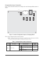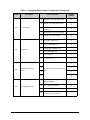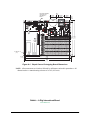
1
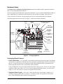
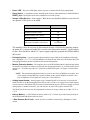
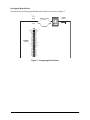
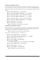
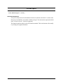
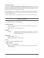
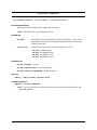
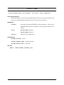
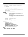
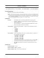
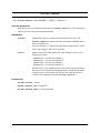
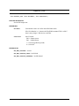
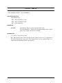
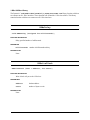
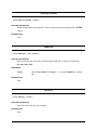
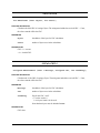
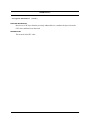
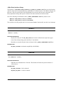
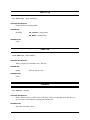
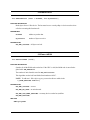
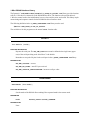
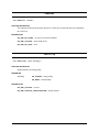
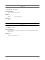
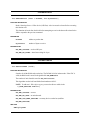
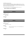
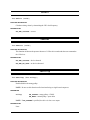
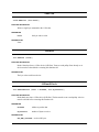
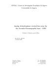
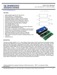
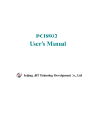
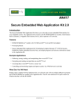
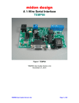
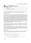
AN420
Simple Sensor Application Kit
Introduction
The Simple Sensor Application Kit provides a design reference for designers to implement the Dallas
1-Wire® bus technology in a Rabbit-based system. These Getting Started instructions and sample applications based on four 1-Wire® devices will help users to better understand and implement this communications bus system using a Prototyping Board and a RabbitCore module.
Features
• RCM4300 RabbitCore module with Prototyping Board
• Includes DS2406 SPST addressable switch, DS18B20 temperature sensor, DS2450 A/D converter, and
DS2480B line driver
• Complete Dynamic C software CD with sample programs and reference information related to the
Application Kit
Example Applications
• Low-cost embedded control applications using 1-Wire bus
• Remote monitoring of equipment, devices, locations
• Simple data-logging applications
What Else You Will Need
Besides what is supplied with the Application Kit, you will need a PC with an available USB port to program the RCM4300. Your PC also needs an RJ-45 jack to allow an Ethernet interface with the RCM4300.
022-0141 Rev. B
1
Interface Options
The Simple Sensor Application Kit provides for four different methods to interface the 1-Wire bus.
1. Direct interface — this interface connects three 1-Wire devices on the 1-Wire bus directly to the Rabbit
microprocessor serial port. The interface uses one serial port at 3.3 V CMOS levels to drive the 1-Wire
bus. (The default configuration is Serial Port C PC3.) The 1-Wire devices have to be located close to the
Rabbit microprocessor.
2. Discrete interface — this interface connects the 1-Wire bus to a high-current discrete driver circuit via
transistors Q1 and Q2 that is controlled by the Rabbit microprocessor serial port. The discrete interface
uses two serial port lines at CMOS levels to interface the transistor driver to the 1-Wire bus. (The
default configuration is Serial Port C PC2 and PC3.) Several 1-Wire devices may be located considerably farther away from the Rabbit microprocessor than in the previous option.
3. Bit-bang direct interface — this interface connects the 1-Wire bus directly to a Rabbit microprocessor I/O
port. The bit-bang interface for a RabbitCore module uses one parallel port line with an open-drain output — the default configuration is Parallel Port C bit 3, PC3. The bit-bang interface for a Rabbit singleboard computer uses two parallel port lines at CMOS levels. The transmit line is buffered to an opencollector/drain transistor output — the default configuration is Parallel Port A bit 1 (PA1) for transmit
and Parallel Port B bit 0 (PB0) for receive.
4. DS2480 line driver interface — the DS2480 line driver interface connects the 1-Wire bus to an integrated component driver that is controlled by the Rabbit microprocessor serial port. The line driver
interface uses two serial port lines at CMOS levels to control the transistor drive to the 1-Wire bus. (The
default configuration is Serial Port C PC2 and PC3.)
022-0141 Rev. B
2
Hardware Setup
The Simple Sensor Application Kit Getting Started instructions included with the Application Kit show
how to set up and program the RCM4300
The Prototyping Board included in the Application Kit makes it easy to connect an RCM4300 module to a
power supply and a PC workstation for development. It also provides four sample 1-Wire devices, a
1-Wire sensors RJ-45 interface, and a prototyping area for more advanced hardware development.
The Prototyping Board is shown below in Figure 1, with its main features identified.
Power
Input
Backup
Optional A/D Converter
Battery
Inputs Header
Power
1-Wire Sensors
LED
RJ-45 Jack
Optional
Pin-Compatible
1-Wire Device
DS18B20
Temperature
Sensor
RCM4300
Module
Connector
DS2406
SPST Addressable
Switch
(U1) DS2406
Indicator LED
Reset
Switch
RCM4300
Standoff
Mounting
+5 V, 3.3 V, and
GND Buses
Through-Hole
Prototyping Area
RCM4300
Module
Extension Header
DS2480B
Line Driver
DS2450
4-channel
A/D Converter
Figure 1. Prototyping Board
Prototyping Board Features
• Power Connection—A a 3-pin header is provided for connection to the power supply. Note that the
3-pin header is symmetrical, with both outer pins connected to ground and the center pin connected to
the raw V+ input. The universal AC adapter provided with the Application Kit is terminated with a
header plug that connects to the 3-pin header in either orientation.
Users providing their own power supply should ensure that it delivers 8–24 V DC at 8 W. The voltage
regulators will get warm while in use. If you want to program the DS2406 memory, you will need to
supply 12 V DC. This feature is currently not supported in the software.
• Regulated Power Supply—The raw DC voltage provided at the 3-pin header is routed to a 5 V
switching voltage regulator, then to a separate 3.3 V linear regulator. The regulators provide stable
power to the RCM4300 module and the Prototyping Board.
022-0141 Rev. B
3
• Power LED—The power LED lights whenever power is connected to the Prototyping Board.
• Reset Switch—A momentary-contact, normally open switch is connected directly to the RCM4300’s /
RESET_IN pin. Pressing the switch forces a hardware reset of the system.
• Sample 1-Wire Devices—Four sample 1-Wire devices are installed, and there is provision for
one optional 1-Wire device to be added.
.
1-Wire Device
Location
DS2406 SPST Addressable Switch
U1
DS18B20 Temperature Sensor
U2
DS2450 4-channel A/D Converter
U4
DS2480B Line Driver
U6
Optional pin-Compatible 1-Wire Device
U3
(not installed)
The installed 1-Wire devices may be disconnected from the 1-Wire bus by removing jumpers
on header JP3. A jumper on header JP6 is used to select between the normal 5 V power supply
for the 1-Wire line driver and the 12 V power supply required to program the DS2406 addressable switch.
• Prototyping Area—A generous prototyping area has been provided for the installation of throughhole components. +3.3 V, +5 V, and Ground buses run along the top of this area. The bottom side of the
Prototyping Board has an area to install surface-mounted components.
• Module Extension Header—The complete pin set of the RCM4300 module is duplicated at header
location P2. Developers can solder wires directly into the appropriate holes, or, for more flexible development, a 2 × 25 header strip with a 0.1" pitch can be soldered into place. See Figure 2 for the header
pinouts.
NOTE: The same Prototyping Board can be used for several series of RabbitCore modules, and
so the signals at P2 depend on the signals available on the specific RabbitCore module. Also,
keep in mind that several signals are used by the 1-Wire interfaces.
• Analog Inputs Header—Analog inputs to the 4-channel DS2450 A/D converter are presented at
header location P3 on the Prototyping Board. JP5 provides a fixed set of voltages from a multi-tapped
resistor network to the DS2450 A/D converter for demonstration purposes. When you supply your own
analog inputs via header location P3, you will first have to remove the jumpers at header JP5.
The DS2450 A/D converter may be programmed in software to accept voltages up to either 2.56 V or
5.12 V.
• Backup Battery—A 2032 lithium-ion battery rated at 3.0 V, 220 mA·h, provides battery backup for
the RCM4300 data SRAM and real-time clock.
• 1-Wire Sensors RJ-45 Jack—An RJ-45 jack is available to connect Digi’s Watchport® 1-Wire
sensors.
022-0141 Rev. B
4
Prototyping Board Pinout
GND
+
GND
The pinouts for the Prototyping Board header interfaces are shown in Figure 2.
Analog
Inputs
P1
D C B A
RCM4300
Signals
+3.3 V
/RST_OUT
/IOWR
VBAT
PA1
PA3
PA5
PA7
PB1
PB3
PB5
PB7
PC1
PC3-RxD
PC5
PC7
PE1
PE3
PE5
PE7
PD1
PD3
PD5
PD7
VREF
P2
P3
GND
/IORD
/RST_IN
PA0
PA2
PA4
PA6
PB0
PB2
PB4
PB6
PC0
PC2-TxD
PC4
PC6
PE0-SPU
PE2
PE4
PE6
PD0
PD2
PD4
PD6
CVT
AGND
Figure 2. Prototyping Board Pinout
022-0141 Rev. B
5
Prototyping Board Jumper Configurations
Figure 3 shows the header locations used to configure the various Prototyping Board options via
jumpers.
JP6
JP5
JP1
JP2
JP3
JP4
Figure 3. Location of Configurable Jumpers on Prototyping Board
Table 1 lists the configuration options using slip-on jumpers.
NOTE: To change the interface type while power is applied, first remove the jumpers on headers
JP1 and JP2, then install the jumpers according to the interface desired.
Table 1. Prototyping Board Jumper Configurations
Header
JP1
JP2
Description
Interface Setup
Pins Connected
1–2
High-current discrete driver interface
5–6
CMOS level direct output or bit-bang
interface
Factory
Default
×
9–10 DS2480B interface
022-0141 Rev. B
6
Table 1. Prototyping Board Jumper Configurations (Continued)
Header
JP3
JP4
JP5
Description
Device Selection
Pins Connected
1–2
DS18B20 (U2) Temperature Sensor
×
3–4
DS2406 (U1) Addressable Switch
×
5–6
RJ-45 Jack for IO Networks 1-Wire
Sensors (J1)
×
7–8
Optional Sensor (U3), not installed
9–10 DS2450 (U4) A/D Converter
×
1–3
DS1 LED to DS2406 (U1)
×
2–4
+3.3 V to DS18B20 (U2)
×
3–5
External load to DS2406 (U1)
4–6
GND to DS18B20 (U2)
7–9
+5 V to J1 pin 5
×
8–10 +5 V to J1 pin 7
×
3–4
×
Connections
A/D Converter Resistor
Divider
5–6
7–8
Three-tap resistor divider for DS2450
inputs
×
×
×
9–10
JP6
Factory
Default
1–3
+12 V supply to allow programming
DS2406 EEPROM
3–5
+5 V supply to DS2480B
6–8
+5 V supply to optional sensor
8–10
GND option for optional sensor if it is
powered from the 1-Wire bus
Power Supply Options
022-0141 Rev. B
×
7
Using a 1-Wire Interface
When you develop your own application based on the Simple Sensor Application Kit, only one bus interface method is likely to be implemented. The Simple Sensor Application Kit provides hardware and software configurations for each interface mode.
Jumper settings are used on the Prototyping Board to connect the 1-Wire bus to the appropriate path.
Headers JP1 and JP2 provide jumper settings for the interface selected, and headers JP3, JP4, JP5, and JP6
control the settings of the various 1-Wire devices. Table 1 lists the various jumper settings.
Software configuration is done via macro settings to select the appropriate port initialization and access.
Macros are provided in the Dynamic C LIB\Rabbit4000\oneWire\1_WIRE_CONFIGURE.LIB
library to select the interface and to control the Rabbit I/O ports and 1-Wire devices used in the Simple
Sensor Application Kit. You should only have to edit the 1_WIRE_CONFIGURE.LIB library to configure your system based on the instructions in the comments in this library.
The configurations are summarized below.
Direct Interface
Hardware
• Header JP1, connect pins 5–6, all other pins are unconnected
• Header JP2, connect pins 5–6, all other pins are unconnected
Software Macros
• #define ONE_WIRE_IF OW_IF_DIRECT
Discrete Interface
Hardware
• Header JP1, connect pins 1–2, all other pins are unconnected
• Header JP2, connect pins 1–2, all other pins are unconnected
Software Macros
• #define ONE_WIRE_IF OW_IF_DISCRETE
Bit-Bang Direct Interface (RabbitCore Modules)
Hardware
• Header JP1, connect pins 5–6, all other pins are unconnected
• Header JP2, connect pins 5–6, all other pins are unconnected
Software Macros
• #define ONE_WIRE_IF OW_IF_BITBANG_RCM
022-0141 Rev. B
8
Bit-Bang Direct Interface (Rabbit Single-Board Computers)
Hardware
• Header JP1, connect pins 5–6, all other pins are unconnected
• Header JP2, connect pins 5–6, all other pins are unconnected
Software Macros
• #define ONE_WIRE_IF OW_IF_BITBANG_SBC
DS2480 Line Driver Interface
Hardware
• Header JP1, connect pins 9–10, all other pins are unconnected
• Header JP2, connect pins 9–10, all other pins are unconnected
Software Macros
• #define ONE_WIRE_IF OW_IF_DS2480
022-0141 Rev. B
9
Sample Programs
The Simple Sensor Application Kit provides seven sample application-level programs that demonstrate
how to write applications that call and use the device function calls at the library level. These sample
programs can be found in the Dynamic C SAMPLES\oneWire folder.
These sample programs demonstrate common event loop processing for device I/O functions, and may be
used as a basis to develop your own applications. Note that the sample programs that include the name of a
1-Wire device are specific to that 1-Wire device.
In order to run these and other sample programs,
1. Your RCM4300 must be plugged into the Prototyping Board as described in the Simple Sensor
Application Kit Getting Started instructions.
2. Dynamic C from the Simple Sensor Application Kit must be installed and running on your PC.
3. The programming cable must connect the programming header on the RCM4300 to your PC.
4. Power must be applied to the RCM4300 via the Prototyping Board.
5. The jumpers must be installed on headers JP1–JP6 on the Prototyping Board according to the device and
the interface being used. The default settings shown in Table 1 will support the sample programs.
Before you compile and run any sample programs, be sure to select Store Program in Flash on the
“Compiler” tab in the Dynamic C Options > Project Options menu. This step is important because the
serial flash is used for program storage on the RCM4300. Also make sure that the Enable Separate
Instruction & Data Space option is selected so that programs requiring more than 512MB of code or
data space will compile successfully.This requirement applies to the OW_RWB.C and OW_RWB_LOG.C
sample programs.
To run a sample program, open it with the File menu, then run it by selecting Run in the Run menu (or
press F9).
022-0141 Rev. B
10
Network Setup for Web Interface Sample Programs
Follow these instructions to set up your PC or notebook for the sample programs that demonstrate a Web
browser interface. Check with your administrator if you are unable to change the settings as described here
since you may need administrator privileges. The instructions are specifically for Windows 2000, but the
interface is similar for other versions of Windows.
TIP: If you are using a PC that is already on a network, you will disconnect the PC from that network to run these sample programs. Write down the existing settings before changing them to
facilitate restoring them when you are finished with the sample programs and reconnect your
PC to the network.
1. Go to the control panel (Start > Settings > Control Panel), and then double-click the Network
icon.
2. Select the network interface card used for the Ethernet interface you intend to use (e.g., TCP/IP Xircom Credit Card Network Adapter) and click on the “Properties” button. Depending on which
version of Windows your PC is running, you may have to select the “Local Area Connection” first, and
then click on the “Properties” button to bring up the Ethernet interface dialog. Then “Configure” your
interface card for a “10Base-T Half-Duplex” or an “Auto-Negotiation” connection on the “Advanced”
tab.
NOTE: Your network interface card will likely have a different name.
3. Now select the IP Address tab, and check Specify an IP Address, or select TCP/IP and click on
“Properties” to assign an IP address to your computer (this will disable “obtain an IP address automatically”):
IP Address : 10.10.6.101
Netmask : 255.255.255.0
Default gateway : 10.10.6.1
Be careful when using Dynamic C since these settings may be overridden by entries under the
“Defines” tab in Project > Options.
4. Click <OK> or <Close> to exit the various dialog boxes.
5. Use the CAT 5/6 Ethernet cable included with this Application Kit to connect the RJ-45 Ethernet jack on
the RCM4300 to your PC or workstation Ethernet jack.
Enter the following server address in your Web browser to bring up the Web page served by the sample
program.
http://10.10.6.100
022-0141 Rev. B
11
Sample Program Descriptions
The sample programs check for and access all the 1-Wire devices, except the DS2480 line driver, which is
only used if the DS2480 interface has been selected.
• 1-WIRE.C—This sample program uses Serial Port C to check for and access the 1-Wire devices
provided in the Simple Sensors Application Kit. A list of the devices and their readings appears in the
Dynamic C STDIO window. The line driver is not read and displayed because it is not an I/O device.
• DS18B20.C—This sample program uses Serial Port C to check for and access the 1-Wire devices
provided in the Simple Sensors Application Kit. A list of the devices and the readings from the
DS18B20 temperature sensor appears in the Dynamic C STDIO window.
• DS18S20.C—This sample program uses Serial Port C to check for and access the 1-Wire devices
provided in the Simple Sensors Application Kit. This sample is for illustration only since no DS18s20
temperature sesnsor is installed on the Prototyping Board. No readings are displayed because there is
no DS18s20 device. Only the ROM table is displayed in the Dynamic C STDIO window.
NOTE: This sample program is included because the device is similar to the DS18B20.
• DS2406.C—This sample program uses Serial Port C to check for and access the 1-Wire devices
provided in the Simple Sensors Application Kit. A list of the devices and the address readings from the
DS2406 addressable switch appears in the Dynamic C STDIO window.
• DS2450.C—This sample program uses Serial Port C to check for and access the 1-Wire devices
provided in the Simple Sensors Application Kit. A list of the devices and the readings from the
DS2450A/D converter appears in the Dynamic C STDIO window.
The network setup described above must be done before compiling and running the remaining two sample
programs.
• OW_RWB.C—This sample program illustrates how to detect and manage 1-Wire devices via a Web
interface. The Web interface uses the Dynamic C RabbitWeb scripting and also uses the Yahoo! User
Interface (YUI) libraries. The Web interface builds a dynamic table of 1-Wire devices and also charts
the current I/O state, which is updated every 2 seconds.
This sample program was developed and tested with Dynamic C 10.46 and YUI version 2.5.2. For more
information on YUI and any technical support related to YUI, you may visit developer.yahoo.com/yui/.
When you compile and run this sample program, as long as you have not modified the TCPCONFIG 1
macro in the sample program, you may enter the following server address in your Web browser to
bring up the Web page served by the sample program.
http://10.10.6.100.
The Web browser will display a list of the devices (except the line driver) and their readings.
022-0141 Rev. B
12
• OW_RWB_LOG.C—This sample program illustrates how to detect and manage 1-Wire devices via a
Web interface. The Web interface uses the Dynamic C RabbitWeb scripting and also uses the Yahoo!
User Interface (YUI) libraries. The Web interface builds a dynamic table of 1-Wire devices and also
charts the current I/O state, which is updated every 2 seconds.
The sample program also uses the miniSD Card on the RCM4300, and will create a onewire folder on
the miniSD Card with subfolders for each of the supported 1-Wire device types. There will be a file for
each member of the device family within the device type folders. File names will be 3 bytes of the
device's 6-byte serial number.
This sample program was developed and tested with Dynamic C 10.46 and YUI version 2.5.2. For more
information on YUI and any technical support related to YUI, you may visit developer.yahoo.com/yui/.
Before you compile and run this sample program, the miniSD Card should be formatted using FAT16.
(See the SAMPLES\FileSystem\FAT\fMT_DEVICE.C sample program for an example on how
to format the miniSD Card.
When you compile and run this sample program, as long as you have not modified the TCPCONFIG 1
macro in the sample program, you may enter the following server address in your Web browser to
bring up the Web page served by the sample program.
http://10.10.6.100.
The Web browser will display a directory of folders for the devices (except the line driver) and their
readings.
022-0141 Rev. B
13
Appendix — Software Reference
Sample Program
A typical sample application will #use the low-level libraries. The example shown below shows a typical
dependency from the application level to the library level.
The only library that needs a #use is the 1_WIRE_CONFIG.LIB library.
#use 1_WIRE_CONFIGURE.LIB
The remaining three libraries listed below are handled automatically,
#use 1_WIRE_DEVICES.LIB
#use 1_WIRE_UTILITIES.LIB
#use 1_WIRE_IF_DIRECT.LIB
Let’s examine some of the code in the OW_RWB.C sample program.
Network Configuration Macros
First, the network configuration used at startup is defined. These macros are used by the parameters in the
function calls, and you may change the macro definitions to suit your needs.
#define TCPCONFIG 1
The TCPCONFIG macro tells Dynamic C to select your configuration from a list of default configurations in the Dynamic C LIB\TCPIP\TCP_CONFIG.LIB library. The usual default of 1 for the
TCPCONFIG macro will set the IP configuration to 10.10.6.100, the netmask to
255.255.255.0, and the nameserver and gateway to 10.10.6.1.
The HTTP server macros set up the RabbitWeb interface for the Web browser. The USE_RABBITWEB
macro is defined to 1 to use the HTTP server enhancements. The SSPEC_MAXNAME macro sets
the maximum length of mime type (default = 20).
#define USE_RABBITWEB 1
#define HTTP_MAXSERVERS 5
#define SSPEC_MAXNAME 128
// using rabbitweb
// improves page loading, uses more memory
// needed for long mime names (*.js)
// Optimizes HTTP Server at the cost of root/xmem memory space
022-0141 Rev. B
14
Debugging Macros
The verbose macro allows you to see detailed bebugging information as the sample program is compiled.
#define LOCAL_VERBOSE 1
// 0 = NO DEBUGGING INFO, 1 = BASIC INFO, 2 = ALL
Additional macros can be defined to provided related information to help with debugging.
OW_VERBOSE
Prints useful info from within the library function calls. The following possible macro values may be OR’d.
1 = device specific functions
2 = detected errors
4 = low-level function calls
8 = intermediate values for search algorithm
OW_DEBUG_IF
Define this macro to be debug to enable debugging the interface library.
OW_DEBUG_DEVICES
Define this macro to be debug to enable debugging the device’s library.
Other Setup Macros
See the next section for additional setup macros used for all the Dynamic C 1-Wire device libraries.
022-0141 Rev. B
15
Function and Macro Reference Guide
The software in the Simple Sensor Application Kit is partitioned into an application level and a device
library level.The application level implements the high-level function calls, and the library level implements the system configuration and low-level device function calls.
The Simple Sensor Application Kit provides six device-level libraries to configure, initialize, and access
1-Wire device function calls.
The following conventions apply.
1. The least significant bit is first.
2. Data are Little-Endian where the least significant byte is the lowest address.
3. The stop bit accomplishes the delay needed for the inter-bit gap in the direct and discrete interfaces.
4. Every command must be preceded by a reset.
The three 1_Wire_IF_… libraries have identical function calls with code specific to the hardware. There
are several function calls that are specific to the hardware and are only used internally by the library. The
intent is that the 1_WIRE_DEVICES.LIB library (in most cases) does not need to “know” which device
is being used.
1-Wire Configuration Library
The Dynamic C LIB\Rabbit4000\oneWire\1_WIRE_CONFIGURE.LIB library is the top-level
library and used to set up the serial port settings for the interface used with the 1-Wire bus. The library
configures the mechanism that drives the 1-Wire bus and prepares the Rabbit processor's serial/parallel port
appropriately. The library contains all the device-specific code and macros for each 1-Wire device implemented in the Simple Sensor Application Kit, and also serves as a wrapper link in the chain of library dependencies. Unless you have something unique to add/modify, this is the only library you should need to edit.
Serial Port Macro
This macro defines which serial port is used — Serial Port A, B, C, D, E, or F. Serial Port C is used by default.
#define OW_SER_PORT C
NOTE: This macro does not set up the serial port I/O pins The sample code in the library shows
the proper method of setting the Rabbit to use the I/O pins for the selected serial port.
Interface Type
Define the ONE_WIRE_IF macro to one (and only one) of the following.
#define ONE_WIRE_IF OW_IF_DIRECT
// connect directly to the Rabbit I/O pin
#define ONE_WIRE_IF OW_IF_BITBANG_RCM // bit "banging" via an RCM
#define ONE_WIRE_IF OW_IF_BITBANG_SBC // bit "banging" via an SBC
#define ONE_WIRE_IF OW_IF_DISCRETE
// use the discrete transistor buffer
#define ONE_WIRE_IF OW_IF_DS2480
// use the DS2480
The OW_IF_DIRECT and OW_IF_DISCRETE modes in the sample code do not use the standard serial
port library. The OW_IF_DS2480 mode does use it.
022-0141 Rev. B
16
Number of A/D Converters
This macro establishes the maximum number of DS2450 A/D converters (two in the example code).
#define DS2450_COUNT 2
Number of 1-Wire Devices
This macro establishes the maximum number of 1-Wire devices allowed on the bus (ten in the example
code).
#define OW_MAX_DEVICES 10
Direct Interface Pullup Register
This macro establishes the pullup register and bit for the direct interface by setting up the open-drain feature for the Tx bit, and uses the CMOS drive for the defined serial port.
NOTE: Do not modify any definitions that use CONCAT.
#define OW_PULLUP_DREG CONCAT (P, CONCAT (OW_SER_PORT, DCR))
#define OW_PULLUP_DSHADOW CONCAT (P, CONCAT (OW_SER_PORT, DCRShadow))
#define OW_PULLUP_BIT 3
Discrete Interface Pullup Register
This macro establishes the pullup register and bit for the discrete interface using the PE0 bit to enable/
disable the strong pullup.
NOTE: Do not modify any definitions that use CONCAT.
#define OW_PULLUP_REG E
#define OW_PULLUP_BIT 0
#define OW_PULLUP_DREG CONCAT (P, CONCAT(OW_PULLUP_REG, DR))
#define OW_PULLUP_DSHADOW CONCAT (P, CONCAT(OW_PULLUP_REG, DRShadow))
#define OW_PULLUP_DDREG CONCAT (P, CONCAT(OW_PULLUP_REG, DDR))
#define OW_PULLUP_DDSHADOW CONCAT (P, CONCAT(OW_PULLUP_REG, DDRShadow))
022-0141 Rev. B
17
Bit Banging via RabbitCore Module
This macro defines the values/registers needed for “bit banging” via a RabbitCore module. These definitions are needed by the driver library. You still need to insert the necessary code in the OWConfigure()
function call to initialize the port. These definitions are used if you are connecting to a single I/O pin of the
Rabbit.
#define OW_BB_DATA PCDR // I/O register
#define OW_BB_DATA_SHADOW PCDRShadow // its shadow
#define OW_BB_DDR PCDDR // data direction register
#define OW_BB_DDR_SHADOW PCDDRShadow // its shadow
#define OW_BB_DCR PCDCR // drive control register
#define OW_BB_DCR_SHADOW PCDCRShadow // its shadow
#define OW_BB_BIT 3 // data bit
#define OW_BB_MASK 1<<OW_BB_BIT
NOTE: Tx and Rx must be a single bit directly on the Rabbit
Bit Banging via Single-Board Computer
This macro defines the values/registers needed for “bit banging” via a single-board computer. These definitions are used if you are using separate Tx and Rx pins, the Tx pin is buffered with an open collector/
drain transistor, and it operates in a normal CMOS mode, not open drain.
NOTE: Any capacitors on the selected I/O pins must be removed.
These values are for a BL2000 using: PA1 = Tx and PB0 = Rx.
#define OW_BB_TXDATA PADR // Tx register
#define OW_BB_TXDATA_SHADOW PADRShadow // its shadow
#define OW_BB_TXBIT 1 // Tx bit
#define OW_BB_TXMASK 1<<OW_BB_TXBIT
#define OW_BB_TXINVERT
// define if the Tx bit gets inverted by the hardware
#define OW_BB_RXDATA PBDR // Rx register
#define OW_BB_RXBIT 0 // Rx bit
#define OW_BB_RXMAS K 1<<OW_BB_RXBIT
NOTE: Strong pullup is not supported in this mode.
022-0141 Rev. B
18
OWConfigure
void OWConfigure (void);
FUNCTION DESCRIPTION
Sets up the serial port based on the hardware interface. By default, Serial Port C is used, but the
library may be modified to use another available serial port. The four interface options described
in the “Interface Options” section are supported.
This function contains code for each of the interface methods. This is the function call to modify
if you change the supported hardware.
022-0141 Rev. B
19
1-Wire Devices Library
The Dynamic C LIB\Rabbit4000\oneWire\1_WIRE_DEVICES.LIB library provides function
calls for the 1-Wire devices in the Simple Sensor Application Kit. The function calls provide for the device
initialization, command start sequence, and read/write sequence. There are no individual device-specific
libraries. All the device-specific functions are in this library.
The function calls that involve 1-Wire timing are specifically for the direct and discrete implementations.All of the interfaces, except the DS2480, require timing calculations. The timing for the DS2480
interface is handled by the chip.
Developers using other 1-Wire devices would add new device-specific function calls into this library.
DS18S20_Convert
int DS18S20_Convert (int UnitNbr);
FUNCTION DESCRIPTION
Tells the specified DS18S20 to start a temperature conversion. The DS18S20 requires 750 ms to
complete a conversion.
NOTE: The family code for the DS18S20 is 0x10.
PARAMETER
UnitNbr
Unit number of the desired DS18S20. If the unit number is -1, then use the
Skip ROM command. This will command multiple DS1820 devices to initiate temperature conversions.
RETURN VALUE
OW_ERR_SUCCESS = success.
OW_ERR_INVALID_UNIT = invalid unit number.
SEE ALSO
OWInit, OWSearchROM, DS18S20_Read
COMMAND SEQUENCE
OWMatch, OW_CMD_TEMPCONV
NOTE: It is up to the caller to implement the required delay between this function call and
DS18S20_Read().
022-0141 Rev. B
20
DS18S20_Read
float DS18S20_Read (int UnitNbr, int Units, float *Degrees);
FUNCTION DESCRIPTION
Reads the temperature value of the specified DS18S20. The device must have already been sent
the convert command and the required delay time (750 ms) must be completed.
PARAMETERS
UnitNbr
unit number of the desired DS18S20. If the unit number is -1, then use the
Skip ROM command. This is valid if there is only a single 1-Wire device on
the bus.
Units
OW_OPT_DEGC = degrees C
OW_OPT_DEGF = degrees F
Degrees
address to place floating result.
RETURN VALUE
OW_ERR_SUCCESS = success.
OW_ERR_INVALID_UNIT = illegal unit number.
OW_ERR_INVAlID_CRC = invalid CRC.
SEE ALSO
OWInit, OWSearchROM, DS18S20_Init
022-0141 Rev. B
21
DS18B20_Convert
int DS18B20_Convert (int UnitNbrr, int Resolution);
FUNCTION DESCRIPTION
Tells the specified DS18B20 to start a temperature conversion.
NOTE: The family code for the DS18B20 is 0x28.
PARAMETER
UnitNbr
unit number of the desired DS18B20. If the unit number is -1, then use the
Skip ROM command. This will command multiple DS1820s to initiate temperature conversions.
Resolution
the delay time required for the desired resolution of 9–12 bits
OW_OPT_9_BITS (94 ms)
OW_OPT_10_BITS (190 ms)
OW_OPT_11_BITS (375 ms)
OW_OPT_12_BITS (750 ms)
RETURN VALUE
OW_ERR_SUCCESS = success.
OW_ERR_INVALID_UNIT = invalid unit number.
OW_ERR_INVALID_PARAMETER = invalid resolution.
SEE ALSO
OWInit, OWSearchROM, DS18B20_Read
COMMAND SEQUENCE
OWMatch, OW_CMD_TEMPCONV
NOTE: It is up to the caller to implement the required delay between this function call and
DS18B20_Read().
022-0141 Rev. B
22
DS18B20_Read
float DS18B20_Read (int UnitNbr, int Units, float *Degrees);
FUNCTION DESCRIPTION
Reads the temperature value of the specified DS18B20. The device must have already been sent
the convert command and the required delay time (750 ms) must be completed.
PARAMETER
UnitNbr
unit number of the desired DS18B20. If the unit number is -1, then use the
Skip ROM command. This is valid if there is only a single 1-Wire device on
the bus.
Units
OW_OPT_DEGC = degrees C
OW_OPT_DEGF = degrees F
Degrees
address to place floating result.
RETURN VALUE
OW_ERR_SUCCESS = success.
OW_ERR_INVALID_UNIT = illegal unit number.
OW_ERR_INVAlID_CRC = invalid CRC.
SEE ALSO
OWInit, OWSearchROM, DS18B20_Init
022-0141 Rev. B
23
DS2450_Init
int DS2450_Init (int UnitNbr, int Channel, int Resolution,
int InputRange);
FUNCTION DESCRIPTION
Sets up an A/D channel. The POR and alarm enable bits will be set to 0.
The DS2450_Init() function call does not affect the bits that control the digital output
capability of the channels.
NOTE: The family code for the DS2450 is 0x20.
PARAMETERS
UnitNbr
Unit Number relative to 0 of the desired DS2450 A/D converter. The
DS2450_COUNT macro must be defined as the number of DS2450 units on
the bus. The default is 1.
If the Unit Number is -1, then use the Skip ROM command. This is valid if
there is only a single 1-Wire device on the bus.
Channel
Channel Number (0–3): 0 = A, 1 = B, 2 = C, 3 = D.
Resolution
Resolution (in number of bits): 1–16,
InputRange
Input Range:
OW_OPT_RANGE_LOW = 0–2.55 V
OW_OPT_RANGE_HI = 0–5.10 V.
RETURN VALUE
OW_ERR_SUCCCESS = success.
OW_ERR_INVALID_UNIT = invalid unit.
OW_ERR_INVALID_CRC = CRC wrong for control byte.
OW_ERR_INVALID_VERIFICATION = incorrect verification.
NOTE: The CRC transmitted by the DS2450 is inverted.
SEE ALSO
OWInit, OWSearchROM, DS2450_ADRead
022-0141 Rev. B
24
DS2450_Convert
int DS2450_Convert (int UnitNbr, int ChannelMask, int ControlMask);
FUNCTION DESCRIPTION
Initiates the A/D converter on the specified channels.
NOTE: The A/D converter requires a conversion time of 80 µs per bit for each channel plus an
overhead of 160 µs for the command. You will need to ensure that there is enough delay before
executing DS2450_ADRead() for the conversions to complete. For example, all four channels at 12-bit resolution will take (4 × 80 µs × 12) + 160 µs = 4 ms.
PARAMETERS
UnitNbr
Unit Number relative to 0 of the desired DS2450 A/D converter. The
DS2450_COUNT macro must be defined as the number of DS2450 units on
the bus. The default is 1.
If the Unit Number is -1, then use the Skip ROM command. This is valid if
there is only a single 1-Wire device on the bus.
ChannelMask
mask for the desired channels — logical-or of any combination of the following:
OW_CHA,
OW_CHB,
OW_CHC,
OW_CHD
ControlMask
mask for controlling the A/D value if no reading is initiated — logical-or of
any combination of the following:
OW_CLRA
OW_CLRB
OW_CLRC
OW_CLRD
or
or
or
or
OW_SETA,
OW_SETB,
OW_SETC,
OW_SETD
You may select only one value for each channel of interest. The OW_CLRx
value tells the A/D converter to set the preconversion value to 0. The
OW_SETx value tells the A/D converter to set the preconversion value to
0xFFFF.
RETURN VALUE
OW_ERR_SUCCESS = success.
OW_ERR_INVALID_UNIT = invalid unit.
OW_ERR_INVALID_CRC = CRC wrong for control bytes.
022-0141 Rev. B
25
DS2450_ADRead
int DS2450_ADRead (int UnitNbr, float * Values);
FUNCTION DESCRIPTION
Reads the A/D converter channels selected in the last DS2450_Convert(). This function call
will store only the values of the requested channels.
PARAMETERS
UnitNbr
Unit Number relative to 0 of the desired DS2450 A/D converter. The
DS2450_COUNT macro must be defined as the number of DS2450 units on
the bus. The default is 1.
If the Unit Number is -1, then use the Skip ROM command. This is valid if
there is only a single 1-Wire device on the bus.
Values
address to store the floating-point results. This should be an array of four
floating-point values:
Values[0] = A/D converter Channel A
Values[1] = A/D converter Channel B
Values[2] = A/D converter Channel C
Values[3] = A/D converter Channel D
Because of the way the readings must be accessed, the data read back from
the A/D converter will include all channels starting with the lowest channel
enabled. However, this function call will only store data into the array
elements for the channels specified by DS2450_Convert().
RETURN VALUE
OW_ERR_SUCCESS = success.
OW_ERR_INVALID_CRC = invalid CRC.
OW_ERR_INVALID_UNIT = invalid unit number.
022-0141 Rev. B
26
DS2406_PIO
int DS2406_PIO (int UnitNbr, int PIOstate);
FUNCTION DESCRIPTION
Sets the PIO output state.
PARAMETERS
UnitNbr
Unit Number relative to 0 of the desired DS2406 switch.
If the Unit Number is -1, then use the Skip ROM command. This is valid if
there is only a single 1-Wire device on the bus.
PIOstate
state I/O mask:
Bit 0 = Output A state
Bit 1 = Output B state
1 = switch on (pulled to ground)
0 = switch off
RETURN VALUE
OW_ERR_SUCCESS = success.
OW_ERR_INVALID_UNIT = invalid unit.
OW_ERR_INVALID_ADDRESS = invalid channel.
022-0141 Rev. B
27
DS2406_Status
int DS2406_Status (int UnitNbr);
FUNCTION DESCRIPTION
Reads the status byte:
Bit 5 = state of Channel A switch
Bit 6 = state of Channel B switch
Bit 7 = power supply flag
PARAMETER
UnitNbr
Unit Number relative to 0 of the desired DS2406 switch.
If the Unit Number is -1, then use the Skip ROM command. This is valid if
there is only a single 1-Wire device on the bus.
RETURN VALUE
≥ 0 = success = the status byte value.
Bits 5 and 6 show the status of the two output switches. When a switch is “on,” its output is low.
The status bit indicates the voltage level of the output; therefore, an “on” switch will show as a
logic 0 in the corresponding position of the status byte.
022-0141 Rev. B
28
1-Wire Utilities Library
The Dynamic C LIB\Rabbit4000\oneWire\1_WIRE_UTILITIES.LIB library function calls that
are common to all 1-Wire interfaces. These function calls control the 1-Wire bus utilities. This library
contains function calls that are common to all 1-Wire interfaces.
OWMsDelay
void OWMsDelay (unsigned int milliseconds);
FUNCTION DESCRIPTION
Delay specified number of milliseconds.
PARAMETER
milliseconds
number of milliseconds to delay.
RETURN VALUE
None.
OWWriteBlock
OWWriteBlock (char * Address, int Count);
FUNCTION DESCRIPTION
Write a block of bytes to the 1-Wire bus.
PARAMETERS
Address
the data address.
Count
number of bytes to write.
RETURN VALUE
None.
022-0141 Rev. B
29
OWDisplayROM
void OWDisplayROM (void);
FUNCTION DESCRIPTION
Displays the ROM table content and the 1-Wire bus hardware selection in the Dynamic C STDIO
window.
RETURN VALUE
None.
OWMatch
void OWMatch (int Index);
FUNCTION DESCRIPTION
Sends reset followed by the match command and the ROM code, or sends reset followed by
OW_CMD_ROM_SKIP.
PARAMETER
Index
index into OW_ROM table (if Index == -1, execute the OWSkip() function
call).
RETURN VALUE
None.
OWSkip
void OWSkip (void);
FUNCTION DESCRIPTION
Sends reset followed by the skip command.
RETURN VALUE
None.
022-0141 Rev. B
30
OWCalcCRC8
int OWCalcCRC (char *Bytes, int Count);
FUNCTION DESCRIPTION
Calculates the 8-bit CRC of a string of bytes. The string must include the received CRC — if not,
the value returned will be the CRC.
PARAMETER
Bytes
the address of the bytes for CRC calculation.
Count
number of bytes to use in the calculation.
RETURN VALUE
CRC = 0 = success.
<>0 = invalid CRC.
OWCalcCRC16
unsigned OWCalcCRC16 (char * Message, unsigned Len, int LoadFlag);
FUNCTION DESCRIPTION
Calculates the 16-bit CRC of a string of bytes. The string must include the received CRC — if not,
the value returned will be the CRC.
PARAMETER
Message
the address of the bytes for CRC calculation.
Len
number of bytes to use in the calculation.
LoadFlag
flag for the CRC “seed”
0 = set the seed to 0
1 = use bytes 0 and 1 for the seed
Note that these bytes must be included in Len.
RETURN VALUE
CRC value.
022-0141 Rev. B
31
OWrxCRC16
unsigned OWrxCRC16 (void);
FUNCTION DESCRIPTION
Receives two CRC bytes from the previously addressed device, combines the bytes to form the
CRC value, and then inverts the result.
RETURN VALUE
The inverted 16-bit CRC value.
022-0141 Rev. B
32
1-Wire Direct Interface Library
The Dynamic C LIB\Rabbit4000\oneWire\1_WIRE_IF_DIRECT.LIB library provides function
calls for 1-Wire devices connected directly to the Rabbit or via a discrete driver. The function calls provide
the basic 1-Wire bus control such as bus initialization, bus reset, bus read, bus write, and search. This
library implements timing and sequence controls for the direct and discrete interface modes.
One of the following two definitions in the 1_WIRE_CONFIGURE.LIB library must be used.
#define ONE_WIRE_IF OW_IF_DIRECT
#define ONE_WIRE_IF OW_IF_DISCRETE
The serial driver for this program does not use the normal serX… function calls, nor does it use interrupts.
OWinit
OWinit (void);
FUNCTION DESCRIPTION
Prepares the serial port. The OW_SER_PORT macro must be defined as the single letter (upper
case) of the serial port being used. Serial Port C is the default.
Remember to set up the I/O pins for the serial port via the 1_WIRE_CONFIGURE.LIB library.
RETURN VALUE
OW_ERR_SUCCESS (to maintain compatibility with DS2480).
OWReset
int OWReset (void);
FUNCTION DESCRIPTION
Sends the reset command to the 1-Wire bus. This function call detects the presence/absence of
1-Wire devices.
RETURN VALUE
OW_ERR_SUCCESS = device detected.
OW_ERR_NO_UNIT = no device detected.
022-0141 Rev. B
33
OWPullUp
int OWPullUp (int Pullup);
FUNCTION DESCRIPTION
Enables/disables the strong pullup.
PARAMETER
Pullup
OW_STRONG = strong pullup
OW_WEAK = normal pullup
RETURN VALUE
None.
OWWrite
void OWWrite (int Data);
FUNCTION DESCRIPTION
Writes a single-byte command to the 1-Wire bus.
PARAMETER
Data
the byte value to write.
RETURN VALUE
None.
OWRead
int OWRead (void);
FUNCTION DESCRIPTION
Reads 1 data byte from a 1-Wire device (LSB first). Turns on weak pullup if not already on. A
device must be selected before executing this function call.
RETURN VALUE
Byte value read from a device.
022-0141 Rev. B
34
OWReadBlock
int OWReadBlock (char * BufAdd, int ByteCount);
FUNCTION DESCRIPTION
Reads bytes from a 1-Wire device. The bus must be set to a weak pullup. A device must be selected before executing this function call.
PARAMETERS
BufAdd
address to put the data.
ByteCount
number of bytes to receive.
RETURN VALUE
OW_ERR_SUCCESS = all bytes received.
OWSearchROM
int OWSearchROM (void);
FUNCTION DESCRIPTION
Searches for all the ROM codes on the bus. If the CRC is valid, the ROM code is stored in the
global table: OW_ROMtable.
The number of units found is stored in: OW_DeviceCount.
This algorithm was derived from Dallas Semiconductor AN187.
NOTE: To add new 1-Wire device types, you need to edit two tables in the
1_WIRE_DEVICES.LIB library.
RETURN VALUE
OW_ERR_SUCCESS = success.
OW_ERR_NO_UNIT = no unit detected.
OW_ERR_TOO_MANY_DEVICES = too many devices on the bus (redefine
OW_MAX_DEVICES).
SEE ALSO
OWDisplayROM
022-0141 Rev. B
35
1-Wire DS2480 Interface Library
The Dynamic C LIB\Rabbit4000\oneWire\1_WIRE_IF_DS2480.LIB library provides function
calls for 1-Wire devices connected via the DS2480B line driver. The function calls provide the basic
1-Wire bus control such as bus initialization, bus reset, bus read, bus write, and search. This library implements timing and sequence controls for the DS2480 line driver interface mode.
The following definition in the 1_WIRE_CONFIGURE.LIB library must be used.
#define ONE_WIRE_IF OW_IF_DS2480
The serial driver for this program uses the normal serX… function calls.
OWinit
int OWinit (void);
FUNCTION DESCRIPTION
Prepares the serial port. The OW_SER_PORT macro must be defined as the single letter (upper
case) of the serial port being used. Serial Port C is the default.
Remember to set up the I/O pins for the serial port via the 1_WIRE_CONFIGURE.LIB library.
RETURN VALUE
OW_ERR_SUCCESS = success.
OW_ERR_NO_BYTES = not all 5 bytes received.
OW_ERR_INVALID_VERIFICATION = incorrect rcvd byte value.
OWSetMode
OWSetMode (int mode);
FUNCTION DESCRIPTION
Sets the mode of the DS2480. Does nothing if the requested mode is the current mode.
PARAMETER
mode
DS2480_DATA or DS2480_COMMAND
RETURN VALUE
None.
022-0141 Rev. B
36
OWReset
int OWReset (void);
FUNCTION DESCRIPTION
This function call detects the presence/absence of 1-Wire devices and sends the reset command to
the 1-Wire bus.
RETURN VALUE
OW_ERR_NO_BYTES = no byte received from DS2480.
OW_ERR_SUCCESS = units found on bus.
OW_ERR_NO_UNIT = error.
OWPullUp
int OWPullUp (int Pullup);
FUNCTION DESCRIPTION
Enables/disables the strong pullup.
PARAMETER
Pullup
OW_STRONG = strong pullup.
OW_WEAK = normal pullup.
RETURN VALUE
OW_ERR_SUCCESS = success.
OW_ERR_INVALID_VERIFICATION = invalid response.
022-0141 Rev. B
37
OWWrite
void OWWrite (int Data);
FUNCTION DESCRIPTION
Writes a single byte to the 1-Wire bus.
PARAMETER
Data
the byte value to write.
RETURN VALUE
None.
OWRead
int OWRead (void);
FUNCTION DESCRIPTION
Reads 1 data byte from a 1-Wire device (LSB first). A device must be selected before executing
this function call.
RETURN VALUE
The byte value read from a device.
022-0141 Rev. B
38
OWReadBlock
int OWReadBlock (char * BufAdd, int ByteCount);
FUNCTION DESCRIPTION
Reads 1 data byte from a 1-Wire device (LSB first). A device must be selected before executing
this function call.
This function call waits four clock ticks before attempting to receive the data to allow time for the
2480 to respond to the previous command.
PARAMETER
BufAdd
address to put the data.
ByteCount
number of bytes to receive.
RETURN VALUE
OW_ERR_SUCCESS = received all bytes.
OW_ERR_NO_BYTES = timed out waiting for a byte.
OWSearchROM
int OWSearchROM (void);
FUNCTION DESCRIPTION
Searches for all the ROM codes on the bus. The DS2480 is left in its data mode. If the CRC is
valid, the ROM code is stored in the global table: OW_ROMtable.
The number of units found is stored in: OW_DeviceCount.
This algorithm was derived from Dallas Semiconductor AN192.
NOTE: To add new 1-Wire device types, you need to edit two tables in the
1_WIRE_DEVICES.LIB library.
RETURN VALUE
OW_ERR_SUCCESS = success.
OW_ERR_NO_UNIT = no unit detected.
OW_ERR_TOO_MANY_DEVICES = too many devices on the bus (redefine
OW_MAX_DEVICES).
SEE ALSO
OWDisplayROM
022-0141 Rev. B
39
1-Wire Bit Bang Interface Library
The Dynamic C LIB\Rabbit4000\oneWire\1_WIRE_IF_BITBANG.LIB library provides function calls for 1-Wire devices connected to parallel outputs. The function calls provide the basic 1-Wire bus
control such as bus initialization, bus reset, bus read, bus write, and search. This library implements timing
and sequence controls for the bit-bang interface mode.
One of the following definitions in the 1_WIRE_CONFIGURE.LIB library must be used.
#define ONE_WIRE_IF OW_IF_BITBANG_RCM
#define ONE_WIRE_IF OW_IF_BITBANG_SBC
OWDelay10
OWDelay10 (void);
FUNCTION DESCRIPTION
Adds 10 µs delay.
RETURN VALUE
None.
OWDelay
OWDelay (int Delay);
FUNCTION DESCRIPTION
Adds a number of 10 µs delays.
PARAMETER
Delay
number of 10 µs intervals (5 ≤ Delay ≤ 255). Note that the Delay value is
not checked for validity.
RETURN VALUE
None.
022-0141 Rev. B
40
OWinit
int OWinit (void);
FUNCTION DESCRIPTION
Calculates timing values by determining the CPU clock frequency.
RETURN VALUE
OW_ERR_SUCCESS = success.
OWReset
int OWReset (void);
FUNCTION DESCRIPTION
This function call detects the presence/absence of 1-Wire devices and sends the reset command to
the 1-Wire bus.
RETURN VALUE
OW_ERR_SUCCESS = device detected.
OW_ERR_NO_UNIT = no devices detected.
OWPullUp
int OWPullUp (int Pullup);
FUNCTION DESCRIPTION
Enables/disables the strong pullup.
NOTE: Do not use this function call when interfacing to single-board computers.
PARAMETER
Pullup
OW_STRONG = strong pullup = CMOS.
OW_WEAK = normal pullup = open drain.
NOTE: If OW_STRONG is specified, the driver is also set to output.
RETURN VALUE
None.
022-0141 Rev. B
41
OWWrite
void OWWrite (int Data);
FUNCTION DESCRIPTION
Writes a single byte command to the 1-Wire bus.
PARAMETER
Data
the byte value to write.
RETURN VALUE
None.
OWRead
int OWRead (void);
FUNCTION DESCRIPTION
Reads 1 data byte from a 1-Wire device (LSB first). Turns on weak pullup if not already on. A
device must be selected before executing this function call.
RETURN VALUE
The byte value read from a device.
OWReadBlock
int OWReadBlock (char * BufAdd, int ByteCount);
FUNCTION DESCRIPTION
Reads data bytes from a 1-Wire device (LSB first). The bus must be set to a weak pullup. A device
must be selected before executing this function call.
PARAMETER
BufAdd
address to put the data.
ByteCount
number of bytes to receive.
RETURN VALUE
OW_ERR_SUCCESS = received all bytes.
022-0141 Rev. B
42
OWSearchROM
int OWSearchROM (void);
FUNCTION DESCRIPTION
Searches for all the ROM codes on the bus. If the CRC is valid, the ROM code is stored in the
global table: OW_ROMtable.
The number of units found is stored in: OW_DeviceCount.
This algorithm was derived from Dallas Semiconductor AN187.
NOTE: To add new 1-Wire device types, you need to edit two tables in the
1_WIRE_DEVICES.LIB library.
RETURN VALUE
OW_ERR_SUCCESS = success.
OW_ERR_NO_UNIT = no unit detected.
OW_ERR_TOO_MANY_DEVICES = too many devices on the bus (redefine
OW_MAX_DEVICES).
SEE ALSO
OWDisplayROM
022-0141 Rev. B
43
Specifications
Table A-1. Prototyping Board Specifications
Parameter
Specification
Board Size
4.10" × 5.55" × 0.56" (97 mm × 97 mm × 14 mm)
Operating Temperature
0°C to +70°C
Humidity
5% to 95%, noncondensing
Input Voltage
8 V to 24 V DC
Maximum Current Draw
800 mA max. for +3.3 V supply,
(including user-added circuits) 1 A total +3.3 V and +5 V combined
Prototyping Area
1.8" × 3.0" (46 mm × 76 mm) throughhole, 0.1" spacing
Connectors
One 2 × 25 header socket, 1.27 mm pitch, to accept RCM4300
One 1 × 3 IDC header for power-supply connection
One 2 × 5 IDC RS-232 header, 0.1" pitch
Two unstuffed header locations for analog and RCM4300 signals
Complete specifications for the RCM4300 RabbitCore module are available in the RCM4300 RabbitCore
User’s Manual.
022-0141 Rev. B
44
0.820
(97)
(104)
(3.7)
(20.8)
4.10
(15.4)
0.145
0.600
3.81
(21.1)
(6.1)
0.831
0.240
RJ-45 jack extends
0.20" (5.0 mm)
past edge of
board
0.125 dia × 4
(3.2)
0.145
(3.7)
5.26
(134)
0.145
(3.7)
5.55
(141)
Figure A-1. Simple Sensor Prototyping Board Dimensions
NOTE: All measurements are in inches followed by millimeters enclosed in parentheses. All
dimensions have a manufacturing tolerance of ±0.01" (0.25 mm).
Rabbit — A Digi International Brand
www.rabbit.com
022-0141 Rev. B
45