1
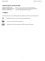
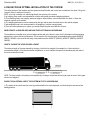
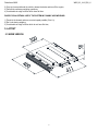
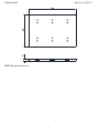
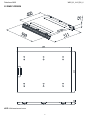
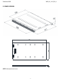
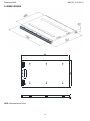
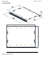
USER MANUAL WWS: WHEEL WEIGHING PLATFORMS WWS_03_14.06_EN_U Piattaforme WWS WWS_03_14.06_EN_U INDICE 1. INTRODUCTION ................................................................................................................................................................. 3 2. MAIN TECHNICAL SPECIFICATIONS ............................................................................................................................... 4 3. SYMBOLS........................................................................................................................................................................... 4 4. RULES FOR AN OPTIMAL INSTALLATION OF THE SYSTEM ........................................................................................ 5 5. LAYOUT.............................................................................................................................................................................. 6 5.1 WWSB VERSION .......................................................................................................................................................... 6 5.2 WWSC VERSION .......................................................................................................................................................... 8 5.3 WWSD VERSION .......................................................................................................................................................... 9 5.4 WWSE VERSION ........................................................................................................................................................ 10 5.5 WWSF VERSION ........................................................................................................................................................ 11 DECLARATION OF CONFORMITY ..................................................................................................................................... 12 WARRANTY ......................................................................................................................................................................... 12 2 Piattaforme WWS WWS_03_14.06_EN_U 1. INTRODUCTION These platforms are designed for creating weighing stations for large vehicles and axle weighing, they are ideal for weighing larger vehicles (vans, trucks, tankers, etc..). WARNING Any attempt to repair or alter the unit can expose the user to the danger of electric shock and it will void our warranty. This instrument is covered under warranty provided that IT HAS NOT BEEN OPENED BY THE USER for any reason. If any problem with the unit or system has been experienced please notify the manufacturer or the dealer from which the instrument was acquired. Do not pour liquids on the indicator Do not use solvents to clean the indicator Do not expose instrument to any heat sources Always mount the platform in a vibration free setting Do not install in an environment with any risk of explosion All the connections of the instrument have to be made respecting the rules applicable in the zone and in the installing environment. Everything not expressly described in this manual has to be considered as improper use of the equipment. The crossed-out wheeled bin on the product means that at the product end of life, it must be taken to separate collection or to the reseller when a new equivalent type of equipment is purchased. The adequate differentiated refuse collection in having the product recycled, helps to avoid possible negative effects on the environment and health and supports the recycling of the materials of which the equipment is made. The unlawful disposal of the product by the user will entail fines foreseen by the current regulations. 3 Piattaforme WWS WWS_03_14.06_EN_U 2. MAIN TECHNICAL SPECIFICATIONS OPERATING TEMPERATURE MINIMUM VOLTAGE PER DIVISION LOAD CELL POWER SUPPLY From -10 to +40 °C (14 to 104 °F) (with even temperature). 0.3 V (approved instrument); 0.03 V (non approved instrument). 5Vdc ± 5%, 120mA (max 8 cells of 350 Ohms) 3. SYMBOLS To call the attention of the user, the following symbols are used both in the manual and on the instrument itself: WARNING! This operation must be performed only by qualified personal. Conforms to the standards of the European Union. Identifies the Class Of Precision defined by the OIML to represent 3000 divisions. 4 Piattaforme WWS WWS_03_14.06_EN_U 4. RULES FOR AN OPTIMAL INSTALLATION OF THE SYSTEM The resting surface of the modules must be coplanar and well leveled, and it must have an hardness of at least 100 kg/cm2 (common value for reinforced concrete); NOTE: a too high inclination can reduce significantly the accuracy of the system; 2) In weighing axes mode is recommended to create a well leveled area around weighing platforms; 3) The underlying fund to the weighing area must support, without failure, concentrated loads of at least 1.5 times the maximum capacity of the module; 4) The weighing performance can be influenced by the type and the state of maintenance of the vehicle weighed; 5) axle weighing mode is not recommended for the weighing of vehicles carrying liquids; 6) Once you have optimized your system, you should always keep the same direction of travel WHEN CREATE A LEVELED AREA AROUND THE PLATFORM, IN AXIS WEIGHING The leveled area is needed when you must weigh vehicles with more than two axles, but it’s advisable in all axle weighing applications to ensure the best performance. For the creation of the leveled area are available leveling module WWSLM (WWSD / WWSE) or the frame for the fixing of the platforms at floor WWSCTF (WWSC), WWSDTF (WWSD), WWSETF (WWSE). HOW TO CHOOSE THE LEVELED AREA LENGHT The minimum length of the area depends by the type of vehicle to be weighed, for example for a 5-axis vehicle the recommended length is 3.5m before and after the platforms, so as to maintain the same level simultaneously the axles of the tractor and those of trailer. NOTE: The best condition of weighing is accomplished by creating a leveled area with a length equal to twice of the longest vehicle to be weighed. RULES FOR AN OPTIMAL USE OF THE SYSTEM IN STATIC AXIS WEIGHING 1) The wheels of the vehicle must be correctly positioned within the centering bands, avoid touching the area around the loading platform; 5 Piattaforme WWS WWS_03_14.06_EN_U 2) Once you have positioned the vehicle, release the brake and turn off the engine; 3) Perform the necessary weighing operations; 4) It’s advisable to weigh vehicles which have flat tires. RULES FOR AN OPTIMAL USE OF THE SYSTEM IN DYNAMIC AXIS WEIGHING 1) Transit at the slowest and more constant speed possible (5 km / h); 2) Don’t curb during weighing; 3) It’s advisable to weigh vehicles which do not have flat tires; 5. LAYOUT 5.1 WWSB VERSION 6 Piattaforme WWS WWS_03_14.06_EN_U NOTE: All dimensions are in mm. 7 Piattaforme WWS WWS_03_14.06_EN_U 5.2 WWSC VERSION NOTE: All dimensions are in mm. 8 Piattaforme WWS WWS_03_14.06_EN_U 5.3 WWSD VERSION NOTE: All dimensions are in mm. 9 Piattaforme WWS WWS_03_14.06_EN_U 5.4 WWSE VERSION NOTE: All dimensions are in mm. 10 Piattaforme WWS WWS_03_14.06_EN_U 5.5 WWSF VERSION NOTE: All dimensions are in mm. 11 Piattaforme WWS WWS_03_14.06_EN_U DECLARATION OF CONFORMITY This device conforms to the essential standards and norms relative to the applicable European regulations. The Declaration of Conformity is available in the web site www.vetek.com WARRANTY The ONE-YEAR warranty period begins on the day the instrument is delivered and covers spare parts and labour if the INSTRUMENTS are returned with prepaid shipping to the DEALER and if the breakdowns are not caused by the customer (so are not included in the warranty, failures resulting from improper use) or during the transport. If on site service isrequested (or is necessary) the customer will be responsible for all of the service technician’s costs: travel time and expenses plus room and board (if any). The customer pays for the shipping costs (both ways), if the instrument is shipped to DEALER or manufacturer for repair. The WARRANTY IS VOIDED if breakdowns happen because repairs have been made by unauthorised personnel or due to connections to equipment installed by others or incorrect connection to the power supply. This warranty DOES NOT PROV IDE for any compensation for damages (indirect or direct) which may cause partial or complete failure of the instruments or systems sold, even if still in the warranty period. AUTHORIZED SERVICE CENTRE STAMP 12