1
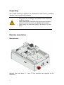
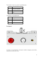
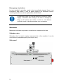
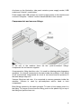
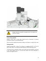
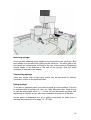
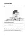
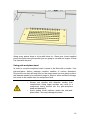
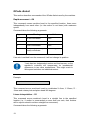
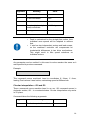
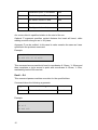
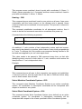
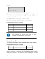
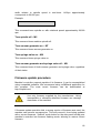
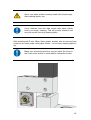
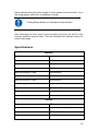
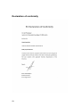
Cirqoid machine
user manual
Table of Contents
Unpacking ..................................................................................... 1 Machine description .................................................................... 1 Machine axes ............................................................................................................... 1 Front panel ................................................................................................................... 2 Emergency stop button ................................................................................................ 3 Manometer ................................................................................................................... 3 Schrader valve ............................................................................................................. 3 Side panel .................................................................................................................... 3 Compressed air and vacuum fittings ............................................................................ 4 Registration pins .......................................................................................................... 5 Add-on heads socket ................................................................................................... 6 Using machine .............................................................................. 6 Switching machine on .................................................................................................. 6 Fixing PCB ................................................................................................................... 7 Spindle add-on ............................................................................. 7 Inserting spindle ........................................................................................................... 7 Connecting spindle ...................................................................................................... 8 Using spindle ............................................................................................................... 8 Dispensing add-on ....................................................................... 9 Inserting syringe adapter ............................................................................................. 9 Inserting syringe......................................................................................................... 10 Connecting syringe .................................................................................................... 10 Using syringe ............................................................................................................. 10 Pick-and-place add-on ............................................................... 11 Inserting pick-and-place head .................................................................................... 11 Connecting pick-and-place head ............................................................................... 11 Using component panels ........................................................................................... 11 Using pick-and-place head ........................................................................................ 12 GCode dialect ............................................................................. 13 Rapid movement – G0 ............................................................................................... 13 Linear interpolation – G1 ............................................................................................ 13 Circular interpolation – G2 and G3............................................................................. 14 Dwell – G4 ................................................................................................................. 15 Homing – G28 ............................................................................................................ 16 Select Machine Coordinate System – G53 ................................................................ 16 Select Work Coordinate System – G54 ..................................................................... 16 Specify Work Coordinate System offsets – G92 ........................................................ 17 Turn spindle on – M3 ................................................................................................. 17 Turn spindle off – M5 ................................................................................................. 18 Turn vacuum generator on – M7 ................................................................................ 18 Turn syringe valve on – M8 ........................................................................................ 18 Turn vacuum generator and syringe valve off – M9 ................................................... 18 Firmware update procedure ...................................................... 18 Maintenance ............................................................................... 19 Vacuum cleaning ....................................................................................................... 19 Cleaning transmission elements ................................................................................ 19 Lubricating transmission elements ............................................................................. 21 Specifications ............................................................................. 22 Declaration of conformity .......................................................... 23 Unpacking
The Cirqoid machine is supplied in a cardboard box with inserts, preventing
machine from moving during shipping.
•
•
•
Be careful not to damage the machine while removing
cardboard inserts!
While removing the machine from the box and carrying it
always hold the machine by the bottom of the case
Never carry the machine holding it by motors or other
parts!
Machine description
Machine axes
Machine has three axes: X, Y and Z. Their directions are depicted on the
illustration.
1
The location of axes’ zero points is specified below:
Axis
Location
X
Left side of machine
Y
Front of machine
Z
Top
Travel limits are specified below:
Axis
Travel limit
X
0..100
Y
0..220
Z
2..-18
Front panel
As shown on the illustration, front panel contains emergency stop button,
manometer and Schrader valve.
2
Emergency stop button
In case machine’s operation needs to be immediately stopped, there is an
Emergence Stop button. It cuts off power supply to all machine’s motors,
vacuum generator, as well as replaceable add-on heads.
E-Stop button does not interrupt machine controller’s power
supply. If machine was moving at the time of emergency
stop, it will resume its motion. If this is not desired,
controller needs to be disconnected from a computer.
Manometer
Manometer indicates air pressure in machine’s compressed air tank.
Schrader valve
Schrader valve is used to supply compressed air to the machine. It can be
used with any compatible pump (car, bicycle, etc.)
Side panel
3
As shown on the illustration, side panel contains power supply socket, USB
socket and “Unbrick” mode button.
Power supply and USB sockets are used to supply power to the machine and
connect it computer. “Unbrick” mode is described later in this manual.
Compressed air and vacuum fittings
At the rear of the machine there are two “push-to-connect” fittings:
compressed air and vacuum supplies.
Compressed air fitting has blue color. It is used in soldering paste dispensing
operation. It is directly connected to the tank inside the machine. If this fitting
is left unconnected, compressed air circuit is not closed and the pressure in
the tank always stays at 0.
Vacuum fitting has red color. It is connected to vacuum generator inside the
machine. Vacuum is used by pick-and-place add-on head to hold
components.
Both fittings operate by the same principle. To insert a hose simply push it in
the fitting. To remove a hose from the fitting, push on the plastic ring on top of
the fitting and pull the hose out.
4
If there is compressed air in the tank, pulling the hose out of
the fitting will release this air.
Registration pins
Machine bed has several holes for registration pins, fixing PCB laminates of
different sizes and component panels.
5
Add-on heads socket
Add-on heads socket it used to connect spindle, dispensing and pick-andplace add-ons to the machine.
Do not let chips and dust to get inside the socket.
Using machine
Switching machine on
Machine needs to be connected to the computer with supplied USB cable.
After the machine is connected to the computer it will be recognized as a
virtual serial port. In case there are other serial ports connected to the
machine, you can determine which one corresponds to the machine by
6
plugging and unplugging the machine and noting, which port appears and
disappears from the list.
If your computer does not recognize the machine, you will need to install a
driver. The machine uses FT232 chip for USB connection, so the driver can
be downloaded at http://www.ftdichip.com/Drivers/VCP.htm
After the machine is connected to the USB port of your computer and
recognized by it, plug the power supply into the respective connector on the
machine.
Use only the power supply that was provided with your
machine. Using an incompatible power supply can damage
the machine.
Fixing PCB
Put a PCB laminate on the machine bed and fix it with the supplied
registration pins. If you are going to do insulation milling pay attention to
laminate edges and holes – they need to be clean from burrs. Should it be
necessary, remove burrs with a sharp knife.
Spindle add-on
Inserting spindle
Spindle is inserted in the machine head and fixed there with a wing nut.
7
Always make sure spindle is properly fixed in the head and
cannot be rotated.
Connecting spindle
Spindle comes with a 9-pin plug, which can be connected to add-ons
connection socket on the machine head.
After connection spindle will produce a beep, confirming it is ready to be used.
Using spindle
Spindle accepts ER11 collets. The machine is supplied with ER11 1/8” (3.175
mm) collet, which is a commonly used diameter of PCB machining tools.
To insert a tool in a spindle, loosen a nut at the end of the spindle, insert tool
in the collet, tighten the nut. You will need 12mm and 17mm wrenches to
loosen and tighten the nut.
8
•
•
•
•
Always insert spindle before connecting it to the
socket
Avoid mechanical impacts on the spindle
Do not let chips and dust to get inside the spindle
Avoid spilling liquids on spindle
It is recommended to use tools with distance rings. This
simplifies Z axis offsets calculations and avoids danger of
extensive damage to the machine as a result of mistake.
Always wear eyes protection when using spindle
PCB laminate chips and dust may contain glass. Always
wear respiratory protection when milling or drilling PCB
Dispensing add-on
Inserting syringe adapter
Syringe adapter is inserted in machine head and fixed there with a wing nut.
9
Inserting syringe
A syringe with soldering paste needs to be connected to the valve box. Blue
hose needs to be inserted into a fitting on the valve box. The other side of the
hose goes into compressed air fitting on the rear of the machine. Dispensing
needle needs to be attached to the end of the syringe. And the entire
assembly is inserted in the adapter.
Connecting syringe
Valve box comes with a 9-pin plug, which can be connected to add-ons
connection socket on the machine head.
Using syringe
To be able to dispense paste, you need to pump air in the machine. This can
be achieved with any pump (car, bike, etc.) with Schrader valve. Pump the air
in, until the manometer reads 1.7 – 2.0 bar. Do not disconnect the pump until
dispensing is finished, as you will need to maintain air pressure in the tank.
As the paste is dispensed, the air is getting consumed, so make sure to
maintain the pressure in the range 1.5 – 2.0 bar.
10
Pick-and-place add-on
Inserting pick-and-place head
Pick-and-place head is inserted in machine head and fixed there with wing
nut.
Connecting pick-and-place head
Pick-and-place head comes with a 9-pin plug, which can be connected to addons connection socket on the machine head.
It also needs to be connected to vacuum fitting at the rear of the machine
(marked red) using supplied red hose.
Using component panels
Pick-and-place add-on is supplied with three components panels: 0-8, 9-12,
12-15. Those numbers indicate the width of the tape pocket.
Choose the panel that fits the components tape you are going to use and put
it on the machine bed as shown. Fix it with supplied registration pins.
11
Along every pocket there is a line with holes for 1.5mm pins. Insert supplied
pins in the holes along the pocket you are going to use and put a tape, so that
it is fixed with the pins.
Using pick-and-place head
In order to use pick-and-place head it needs to be fitted with a needle. Your
pick-and-place add-on package contains needles of various diameters.
Choose the one that will work best for the components you are going to place:
the diameter needs to be sufficiently large to allow for some surface coverage,
but needs to be smaller than the component itself.
•
•
Always use needles with diameter smaller than
components! Using larger needles can result in a
component being sucked into the pick-and-place
head and damage it.
Avoid getting small particles inside the pick-andplace head – this may damage the head
12
GCode dialect
This section describes commands of the GCode dialect used by the machine.
Rapid movement – G0
This command moves machine head to the specified location. Axes move
independently from each other (i.e. the motion is not linear) with maximum
speed.
Command takes the following arguments:
Argument
Meaning
Units
X
X axis coordinate
mm
Y
Y axis coordinate
mm
Z
Z axis coordinate
mm
A
A axis (pick-and-place 1/100 degree
head) coordinate
If an axis is omitted from the command, it will not change its position.
Y axis has two independent motors and lead screws, so the
machine’s controller will compensate for insubstantial
differences in two drive mechanisms. This might result in
little speed variations on individual motors.
Example:
G0 X0 Y20 Z-10 A3.6
This command moves machine’s head to coordinates X: 0mm, Y: 20mm, Z: 10mm and rotates pick-and-place head 360 degrees.
Linear interpolation – G1
This command moves machine’s head in a straight line to the specified
location (i.e., if motion is commanded on more than one axis, their motions
will be synchronized to achieve straight line movement).
Command takes the following arguments:
13
Argument
Meaning
Units
X
X axis coordinate
mm
Y
Y axis coordinate
mm
Z
Z axis coordinate
mm
A
A axis (pick-and-place 1/100 degree
head) coordinate
F
Feed (speed of motion)
•
•
mm/min
Feed is maintained for the straight line motion, thus
individual axes speeds will be adapted to achieve
that.
Y axis has two independent motors and lead screws,
so the machine’s controller will compensate for
insubstantial differences in two drive mechanisms.
This might result in little speed variations on
individual motors.
Any parameter can be omitted. In this case its value remains the same as it
was specified in previous command.
Example:
G0 X10 Y0 F300
This command moves machine’s head to coordinates X: 10mm, Y: 0mm,
leaving Z axis where it was before, maintaining speed at 300mm/min.
Circular interpolation – G2 and G3
These commands move machine head in an arc. G2 command moves in
clockwise motion, G3 – in counterclockwise. Circular interpolation only works
in XY plane.
Command takes the following arguments:
Argument
X
Meaning
Destination point X coordinate
Units
mm
14
Y
Destination point Y coordinate
mm
Z
Destination point Z coordinate
mm
I
Arc center offset in X axis
mm
J
Arc center offset in Y axis
mm
F
Feed (speed of motion)
mm/min
Arc center offset is specified relative to the start of the arc.
Optional Z argument specifies vertical distance the head will travel, while
making a motion along an arc in XY plane.
Argument F can be omitted. In this case its value remains the same as it was
specified in the previous command.
Example:
G0 X30 Y50
G2 X30 Y50 J5 I5 F300
This command moves machine’s head to coordinates X: 30mm, Y: 50mm and
then completes a circle around a point with coordinates X: 35mm, Y: 55m,
maintaining feed at 300 mm/min.
Dwell – G4
This command pauses machine execution for the specified time.
Command takes the following arguments:
Argument
P
Meaning
Pause duration
Example:
G0 X30 Y50
G4 P1.5
G0 X40 Y60
15
Units
Seconds
This program moves machine’s head to point with coordinates X: 30mm, Y:
50mm, pauses execution for 1.5 seconds and then moves machine’s head to
point with coordinates X: 40mm, Y: 60mm.
Homing – G28
This command moves machine’s head to zero points on all axes. Axes move
sequentially until the home sensor on the relevant axis is passed. Home
sensors locations are considered to be zero points. This process is referred to
as homing.
This command establishes coordinates for all subsequent motions, thus it
needs to be the first command executed on a machine after power up.
Command takes the following arguments:
Argument
Y
Meaning
Difference between Y axis zero points
Units
mm
As machine’s Y axis consists of two independent motors and lead screws,
they need to be placed in a position, which makes X axis strictly perpendicular
to Y axis. To achieve this, this position was measured during machine’s QA
test and was supplied to you on a test report sheet.
This value needs to be passed to G28 command every time, so that after
identifying home sensors on both sides of Y axis, machine could restore the
ideal position of Y axis independent sides.
Example:
G28 Y0.835
This command moves all axes to their respective zero points and establishes
Y axis zero point so, that the right side of the axis is 0.835mm further away
from its home sensor than left side.
Select Machine Coordinate System – G53
This command select Machine Coordinate System as an active coordinate
system. All coordinates in subsequent commands will be interpreted with
respect to machine’s zero points.
Select Work Coordinate System – G54
This command selects Work Coordinate System (user defined) as an active
coordinate system. All coordinates in subsequent commands will be
interpreted with respect to the offsets specified in Work Coordinate System.
16
Example:
G92 X15 Y100 Z-5
G54
G0 X10 Y 20 Z0
This program selects the following offsets for Work Coordinate System: X:
15mm, Y: 100mm, Z: -5mm. Then it makes Work Coordinate System active
and moves machine’s head to the position X: 25mm, Y: 120mm, Z: -5mm (in
machine’s coordinates).
Specify Work Coordinate System offsets – G92
This command specifies the offsets for Work Coordinate System.
Command takes the following arguments:
Argument
Meaning
Units
X
X coordinate offset
mm
Y
Y coordinate offset
mm
Z
Z coordinate offset
mm
This command only specifies the offsets for Work
Coordinate System. It does not make it active!
Turn spindle on – M3
This command turns machine spindle on. Spindle always rotates clockwise.
Command takes the following arguments:
Argument
S
Meaning
Speed of rotation
Units
µs
Speed is specified as a width of a PWM pulse, supplied to motor controller.
Speed can be specified in the range [1000..1400] microseconds. The pulse
17
width relation to spindle speed is non-linear. 1400µs approximately
corresponds to 30,000 rpm.
Example:
M3 S1350
This command turns spindle on with rotational speed approximately 28,000
rpm.
Turn spindle off – M5
This command turns machine spindle off.
Turn vacuum generator on – M7
This command turns vacuum generator on.
Turn syringe valve on – M8
This command turns syringe valve on.
Turn vacuum generator and syringe valve off – M9
This command turns off both vacuum generator and syringe valve, regardless
of their states.
Firmware update procedure
Machine’s controller supports update of its firmware. It can be accomplished
using compatible software. We recommend using cirQWizard application for
this purpose. The most recent firmware can be downloaded at
http://cirqoid.com/
Use only firmware supplied by the manufacturer. Using
incompatible or otherwise defective firmware can damage
electronics of the machine!
If firmware update operation fails or wrong version of firmware was used, the
machine can become unresponsive. This will prevent it from being updated
with a correct firmware. “Unbrick” mode button on the side panel forcibly puts
machine’s controller into firmware flashing mode, allowing to restore correct
firmware.
18
Maintenance
Your machine needs regular maintenance. Frequency of maintenance
depends on intensity of use. If machine is used intensively, we recommend
performing maintenance every week. If machine is used occasionally,
maintenance can be performed once a month.
If maintenance time has not come yet, but you observe
considerable amount of dust and dirt on linear guides,
bushes or lead screws – clean the machine. This will make
it last longer.
Before beginning machine maintenance move X and Y axes to the center of
the machine and Z axis to the top – this will provide you with an access to all
the parts of the machine that need to be serviced.
Follow operations described below step-by-step.
Vacuum cleaning
Use a vacuum cleaner to clean all dust and dirt from the machine. Pay
particular attention to registration pin holes.
•
•
Dust left after machining PCB laminate may contain
tiny particles of glass, which are harmful to inhale.
Always use HEPA vacuum cleaners
Always dispose of the vacuum cleaner bag after
cleaning PCB laminate dust
PCB laminate chips and dust may contain glass. Always
wear respiratory protection while cleaning the machine
Cleaning transmission elements
Clean old grease and dirt from linear guides, bushes, lead screws and lead
screw nuts. Use white spirit or aerosol degreaser. If you use white spirit, you
can apply it with a brush.
19
Never use water-soluble cleaning liquids (like liquid soaps,
dish washing liquids, etc.)
Cover machine bed and side covers with paper towels
before you begin cleaning. This will protect machine bed
and side covers from dirty cleaning liquid
Start cleaning with Z axis. When linear guides, bushes, lead screws and lead
screw nut are clean, wipe it with paper towels – do not leave cleaning liquid to
dry.
Make sure cleaning liquid does not get inside the holes in
the Z axis motor mount or inside add-on connection socket
20
Proceed with cleaning X and Y axes. Pay particular attention to cleaning lead
screws and lead screw nuts.
Avoid getting cleaning liquid on magnetic strips and other
areas highlighted on the illustration below. If you
accidentally spill it there – immediately remove with a paper
towel
Lubricating transmission elements
Replace paper towels you used while cleaning the machine with new ones.
It is advised to use either synthetic grease or adhesive aerosol lubricants to
lubricate your machine. If you use grease, it can be applied with a brush.
Do no use liquid lubricants or oils
21
Apply lubricant along the entire length of linear guides and lead screws. If you
are using grease, make sure to distribute it evenly.
Avoid getting lubricant on other parts of the machine
After lubricating all axes, power up the machine and move all axes to their
extreme positions several times. This will distribute the lubricant along the
entire travel range.
Specifications
Machine
Max PCB size
100x160mm
Mechanical resolution
0.01mm
Software resolution
1.25µm
Repeatability
< 0.02mm
Max travel speed, X axis
1200mm/min
Max travel speed, Y axis
1000mm/min
Max travel speed, Z axis
1500mm/min
Power supply
19V DC, 4.5A
Dimensions
280x470x380mm
Weight
14kg
Spindle
Chuck
ER11
Tool collet
ER11 3.175mm (1/8”)
Speed
7,000 to 30,000rpm
Run-out
< 0.03mm
22
Declaration of conformity
23