1
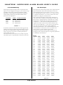
SMARTERM
SUPERVISED ALARM BOARD USER’S GUIDE
Smarterm
Supervised
Alarm Board
User’s Guide
Page 1 of 6
SMARTERM
SUPERVISED ALARM BOARD USER’S GUIDE
TABLE OF CONTENTS
1.1.
Smarterm Supervised Alarm Board, Revision C
1.1.1.
PREFACE
1.1.2.
Introduction
1.1.3.
Features
1.1.4.
Item Checklist
3
3
3
3
3
1.2.
3
System Requirements
1.3.
Board Description
1.3.1.
Power Requirements
1.3.2.
Data/Control
1.3.3.
Board Addressing
1.3.4.
Alarm Inputs
3
3
3
4
4
1.4.
Installation
1.4.1.
How to use the Supervised Alarms:
1.4.2.
Supervised Alarm Message Interpretation:
5
5
5
1.5.
6
For firmware versions later than 4.11
SMARTERM
SUPERVISED ALARM BOARD USER’S GUIDE
1.2. System Requirements
PRELIMINARY
1.1. Smarterm Supervised Alarm Board,
Revision C
1.1.1. PREFACE
Congratulations on your purchase of the Continental Instruments Supervised Alarm board. This device enhances the
monitoring capabilities of your existing Smarterm system.
The Supervised Alarm board is an American-made product and
is covered by a 1-year warranty. Each unit is subjected to a
"burn-in" period and completely tested prior to shipment. Once
properly integrated into your system, it will provide years of
trouble-free service.
The Supervised Alarm board requires a Smarterm running a
firmware revision of 3.0 or later. As a result, the Smarterm itself
must be a hardware revision E.3, F.3, H, or later.
In order to determine the firmware revision level of your
Smarterm, locate the chip with the paper label on it. If the
version is lower than 3. 0, contact Continental Instruments for
instructions on how to upgrade your firmware.
The hardware revision level information is located in the upper
left hand corner of your Smarterm. If it does not conform to
the specifications described above, contact Continental Instruments for instructions on how to upgrade your hardware.
1.3. Board Description
1.3.1. Power Requirements
12Vdc:
1.1.2. Introduction
This section describes various components of the Supervised
Alarm board. It acquaints you with the parts of the board and
their names and locations so that references made to these parts
later on in this document can be easily understood.
Provided at J17 by the supplied power cable.
A completely wired power cable has been supplied for your
convenience. One end is fitted with a Buchanan connector for
attachment to the Supervised Alarm board at J19. The other end
consists of a pair of tinned leads, which will be connected to the
existing Smarterm battery backup system.
I
1.3.2. Data/Control
1.1.3. Features
§
Sixteen supervised alarm inputs
§
Transient protection on all inputs
§
Software indication of normal, abnormal, short, open, or
ground fault status
§
Revision C board supports battery backed operation
1.1.4. Item Checklist
Carefully unpack the Supervised Alarm installation kit and
verify that all items listed below are present and in good condition. If any item is determined to be damaged or missing, please
contact Continental Instruments immediately.
Qty.
1
1
6
6
6
1
1
CIC p/n
170-1093
210-1134
280-1061
280-1003-10
280-1002-7
A 34-position ribbon cable has been supplied. When connected,
it allows the Smarterm to monitor the status of the Supervised
Alarm board. It is fitted with two 34-position dual row
connectors, one attached to either end of the ribbon cable. Pin
1 can be identified either by a triangle on the 34-position dual row connector or by the edge of the ribbon cable with the red
trace.
Interconnection is accomplished by aligning the pin 1 indication
on the cable with the silkscreen designation for pin 1 on the
printed circuit board. On the Smarterm, this cable is to be
attached to J20. On the Supervised Alarm board, the cable may
be attached to either PI or P2. You will note that it is necessary
to place a twist in the ribbon cable in order to properly connect
the Smarterm to the first expansion board.
P1 and P2 on the Supervised Alarm board are identical and
allow connection to Smarterm and/or other expansion boards
from either connector. In this way, up to four expansion boards
may be controlled by a single Smarterm by daisy-chaining the
connections.
Description
Supervised Alarm board for Smarterm
34-position ribbon cable
16 nylon standoffs - 3/811 long
J6 fiber washers
6-32 hex nuts
Supervised Alarm Board Power Cable
Supervised Alarm User's Manual
Page 3 of 6
SMARTERM
SUPERVISED ALARM BOARD USER’S GUIDE
1.3.4. Alarm Inputs
1.3.3. Board Addressing
Each Supervised Alarm board provides 16 supervised alarm
inputs. It can be configured to occupy any one of the four logical address select spaces not already occupied by another
Expanded 1/0 board, Supervised Alarm board, or RUSCO
reader interface board. The actual alarm numbers can be
derived from the table below.
ADDRESS
CSX1
CSX2
CSX3
CSX4
LABEL ALARM NUMBER
X1 Alarms 17-32
X2 Alarms 33-48
X3 Alarms 49-64
X4 Alarms 65-80
TABLE 1-1
It should be noted at this time that there will be gaps in relay
numbers when using the Supervised Alarm boards. For example, if all four attached boards are Supervised Alarm boards,
relays 9-24, 25-40, 41-56, and 57-72 will be physically nonexistent within the system.
Care must be taken to ensure that no two boards occupy the
same address space or unpredictable consequences will result.
Each Supervised Alarm board provides sixteen supervised alarm
inputs for Smarterm. Each of these alarm input contact sets
(ALxxH=high and ALxxL=low) expects a connection to a set of
dry contacts through a resistive termination. These contacts can be
any magnetic reed switch or a set of relay contacts that do not
introduce any voltage into the alarm circuit.
Each supervised alarm input requires special termination in
order to provide true supervisory monitoring of an input. The
inputs expect a nominal resistance of 1000 ohms in a normal
(closed) circuit, and 2000 ohms in an abnormal (open) circuit.
A 1000 ohm +/- 10% resistor should be placed across the
magnetic reed switch contacts that are shorted with the door
closed. A second 1000 ohm +/- 10% resistor is also placed in
series with the switch. This circuit will then fulfill the requirements specified above. It is recommended that these resistors be located in a secured area as close as possible to the
switch contacts to ensure optimal system security.
The physical connections for these inputs are located at J1
through J16. The actual alarm inputs as recognized by Smarterm
are identified in the table below.
Board
Address CSX1
J1-1
J1-2
J2-1
J2-2
J3-1
J3-2
J4-1
J4-2
J5-1
J5-2
J6-1
J6-2
J7-1
J7-2
J8-1
J8-2
J9-1
J9-2
J10-1
J10-2
J11-1
J11-2
J12-1
J12-2
J13-1
J13-2
J14-1
J14-2
J15-1
J15-2
J16-1
J16-2
AL17H
AL17L
AL18H
AL18L
AL19H
AL19L
AL20H
AL20L
AL21H
AL21L
AL22H
AL22L
AL23H
AL23L
AL24H
AL24L
AL25H
AL25L
AL26H
AL26L
AL27H
AL27L
AL26H
AL28L
AL29H
AL29L
AL30H
AL30L
AL31H
AL31L
AL32H
AL32L
CSX2
AL33H
AL33L
AL34H
AL34L
AL35H
AL35L
AL36H
AL36L
AL37H
AL37L
AL38H
AL38L
AL39H
AL39L
AL40H
AL40L
AL41H
AL41L
AL42H
AL42L
AL43H
AL43L
AL44H
AL44L
AL45H
AL45L
AL46H
AL46L
AL47H
AL47L
AL48H
AL48L
CSX3
AL49H
AL49L
AL50H
AL50L
AL51H
AL51L
AL52H
AL52L
AL53H
AL53L
AL54H
KL54L
AL55H
AL55L
AL56H
AL56L
AL57H
AL57L
AL58H
AL58L
AL59H
AL59L
AL60H
AL60L
AL61H
AL61L
A562H
AL62L
AL63H
AL63L
AL64H
AL64L
Table 1-2
Page 4 of 6
CSX4
AL65H
AL65L
KL66H
XL66L
AL67H
KL67L
KL68H
KL68L
AL69H
KL69L
AL70H
AL70L
AL71H
AL71L
AL72H
AL72L
AL73H
AL73L
AL74H
AL74L
AL75H
AL75L
AL76H
AL76L
AL77H
AL77L
AL78H
AL78L
AL79H
AL79L
AL80H
ALBOL
SMARTERM
SUPERVISED ALARM BOARD USER’S GUIDE
1.4. Installation
The actual hardware installation is fairly simple and
straightforward. Briefly, the board and power cord assembly will
be mounted in the cabinet, and all cables are then interconnected. The following steps provide a detailed description of this
procedure. All references to the case assume it is mounted
vertically on a wall. Please read all instructions thoroughly before
beginning.
Inside the Smarterm cabinet base:
1.
Remove the power from the Smarterm by lifting the five
position Buchanan connector off of J9.
2.
Disconnect the negative (black) terminal from the battery.
3.
Connect the two wire power cable to the J9 Smarterm
power connector (removed in step 2.1) using the end of the
power cable with the tinned leads. Secure the black lead to
J9-1 (marked B-) and the red lead to J9-2 (marked B+).
Then, using the supplied spot ties and adhesive-backed
anchors, route the two wire power cable inside the cabinet
so that it will be near the Supervised Alarm board J9
connector when it is installed. Ensure that enough slack is
left in the power cable to allow the hinged door to open
and close without interference.
11. Install all of the alarm input wiring necessary for your
application. Please refer to section 1.4.4 for a complete description of alarm signal names and interconnection
requirements.
12. Install the end of the two wire power cable with the
Buchanan connector onto the Buchanan connector at J19
of the Supervised Alarm board. Ensure that the power
cable's red wire is connected to J19-1 (indicated by +) on
the Supervised Alarm board. The black wire should be
connected to J19-2, the pin next to the fuse (indicated by
-).
13. Replace the five position Buchanan connector at J9 of' the
Smarterm. This is the same connector you removed in
section 2.1 of this procedure.
14. Replace the negative (black) lead to the battery removed in
step 2.2.
This completes the hardware installation phase.
On the Smarterm cabinet cover:
4.
10. Attach the other end of the data/control ribbon cable to
J20 of the Smarterm, while once again maintaining proper
pin 1 alignment. (Please refer to section 1.4.2.) If a board
(or boards) other than this new Supervised Alarm board
already exist on the Smarterm cabinet cover, place the
other end of the data/control ribbon cable on the left-hand
34 position dual row header of the adjacent board. Be sure
to maintain proper pin 1 alignment.
Place six 3/811 nylon standoffs on the six threaded studs
closest to the hinge assembly. If a board (or boards) already
exist on the cover, use the next six available studs closest to
the hinge assembly.
5.
Place the Supervised Alarm board on these studs, making
sure that the dual row header labeled P2 is closest to the
Smarterm dual row header labeled J20.
6.
Place six fiber washers on the threaded studs that the board
has been mounted on.
7.
Now secure the Supervised Alarm board assembly to the
door using six 6-32 hex nuts.
8.
Place the shorting block across an appropriate CSX jumper
header to select the proper board address. Please refer to
section 1.4.3 for a complete discussion on how to use this
jumper.
9.
Attach one end of the data/control ribbon cable to P2 on
the Supervised Alarm board. (This is the 34 conductor
ribbon cable with a dual row connector at either end.) Be
sure to align the pin 1 indicator on the cable with the silk
screened pin I designator on P2 of the Supervised Alarm
board.
1.4.1. How to use the Supervised Alarms:
Configuration of these alarms and relays is similar to that of the
Smarterm on-board alarms and relays. A discussion of alarm
and relay configuration can be found in the Smarterm
Operator's Manual.
The Supervised Alarm board will provide three new messages in
addition to the 'normal' and 'abnormal' status messages ordinarily provided. These new alert messages supply additional
information about the type of abnormality sensed at the alarm
input.
1.4.2. Supervised Alarm Message
Interpretation:
Normal
A 'normal' message indicates that the circuit being monitored
has sensed that the conditions are met for a normal state.
Abnormal
An 'abnormal' message indicates that the point being monitored
has gone into an abnormal condition, but the interconnection
between that point and the Supervised Alarm board is still in
good condition.
Open
An 'open' message indicates that there is an interruption in
continuity between the Supervised Alarm board and the point
Page 5 of 6
SMARTERM
SUPERVISED ALARM BOARD USER’S GUIDE
being monitored. This condition is typically the result of a cut in
the wiring.
Short
A 'short' message indicates that the interconnecting wiring is
shorted somewhere between the Supervised Alarm board and
the point being monitored. This can be the result of a pinched
cable or an unauthorized attempt at defeating the alarm system.
Ground Fault
A 'ground fault' message indicates that one of the sensing wires
has come in contact with a ground potential. This can be caused
by an un-insulated section of wire touching the inside of the
conduit it is running through.
1.5. For firmware versions later than 4.11
Host software (Manage or CA450) must be used to ascertain the
status of the inputs
•
Enable one or more inputs on the Supervised Alarm board
•
Display the input status screen on the host software
•
Check display information against anticipated status
•
Change the status of the enabled input(s) and verify that
the change is properly reflected on the host .status screen
If you are unable to resolve your problem, please call
Continental Instruments LLC at (516) 254-0044. Ask to speak
with someone in Technical Support regarding the Supervised
Alarm board for Smarterm.
Before you call, gather your notes about what the specific
problem is and what you have done in your attempt to resolve
it. Have your system up and running with a telephone nearby.
The technician will discuss your problem with you and guide
you through some troubleshooting procedures to determine the
cause of your difficulty.
Page 6 of 6