1
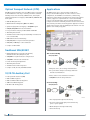
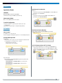
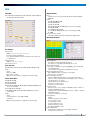
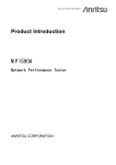
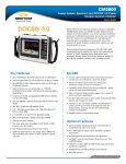
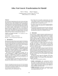
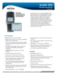
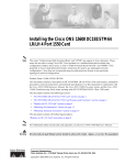
STT 40G
43G OTN and 40G SDH/SONET Testing
Now with optional DPSK line coding
The versatile and powerful STT 40G takes Sunrise Telecom’s
Scalable Test Toolkit (STT®) platform to a new level as a test and
measurement solution for high speed transport networks such
as 43G OTN (OTU3) and 40G SDH/SONET (STM-256/OC-768).
With payload structure down to VC12, VC11, VT1.5, and VT2,
it offers service providers a complete test solution for today’s
and tomorrow’s Metro, Core, and DWDM transport networks. In
addition to it, STT 40G now offers 43G DPSK modulation with
tunable transmitter for OTN Network Element client and line side
field verification. Its small size and weight in stand alone mode
makes the STT 40G the smallest and lightest test set in the world.
This commanding set of features is available in a single, compact,
easy to use, and cost effective unit. The STT 40G can be used
independently or combined with other test modules to enhance
its application, taking advantage of its bidirectional 10.7/10G
drop and insert port. Like other STT modules the STT 40G offers
the revolutionary and cost-effective stand-alone mode in remote
or local environments, allowing test modules to operate at 100%
of their capabilities and features, even when removed from the
STT platform.
Key Features
• OTN, SDH, SONET in one instrument
• Optional DPSK modulation for OTN NE line side
verification in the field
• 10/10.7G auxiliary port to interconnect STT 40G module
with other 10G systems
• Fully independent or can be combined with other test
modules to enhance application
• Internal SDH/SONET mapping down to VC12, VC11, V T1.5, VT2
• Complete performance tests and analysis for point to point
links and DWDM networks
• Comprehensive SDH/SONET/OTN overhead control and decode
• Auto-configuration
• Stand-alone operation (no platform required) increases
portability and flexibility
• Complies to ITU-T, Telcordia, and ANSI standards
• Intuitive user-friendly, yet powerful, Graphical User Interface
Benefits
• All-in-one transport networks test solution
• Cost-effective solution, as a stand-alone module,
self-contained portable instrument, or as a 40/43G complement to existing STT ONE reducing CAPEX
• Eliminates the need for multiple platforms
• Increases availability of test gear as STT modules left
behind can be used at 100% of their capabilities, while the test platform is being used in other application.
• Native Remote Control operation that can work on low bandwidth conditions, offering the most responsive system in the market.
The user-interface has been designed specifically for carrier,
NEMs, and lab applications, maintaining the familiar look and
feel of other STT products to reduce the learning curve and
operational expenses. Auto configuration takes the guess-work
out of configuring the instrument to the circuit being tested. Yet,
experienced users will appreciate advanced features like overhead
monitoring and control, APS timing measurement, pointer test
sequences, and propagation delay measurement.
Test Features
With its comprehensive set of test and measurement features, the
STT 40G allows the user to perform routine and advanced testing
on high speed transport networks with a single platform.
All measurements conform to industry standards, and circuit
impairments are displayed on a correlated graphical view, giving
operators insight into the possible causes of circuit impairments.
By combining the STT 40G with STT ONE, it offers a cost effective
solution for testing all transport networks from 1.5 or 2 Mbit/s up
to 40/43 Gbit/s, eliminating the need for multiple platforms.
• Same look and feel as other STT modules reduces
the learning curve and operational expenditures
• Ideal for Network Element installation, verification and troubleshooting
www.sunrisetelecom.com
Optical Transport Network (OTN)
Applications
STT 40G provides Forward Error Correction (FEC), verifies conformance
to ITU-T G.709 and a wide range of network performance standards,
including end-to-end connectivity at OTU3 bit rate, and complete
synchronous/asynchronous mapping of SDH STM-256, SONET OC-768
client signals.
STT 40G allows the user to perform testing on high-speed
transport networks. Offering both in-service and out-of-service
configurations, the STT 40G covers installation, commissioning,
maintenance and troubleshooting applications. Among other advance
features, it supports a comprehensive set of test modes including
point-to-point, through modes, mux-test and mux emulation. Its
complete error insertion and alarm generation selection can be used to
verify network performance monitoring systems. Application oriented
graphical user interface shows the building blocks and flow of the test
signals as user friendly set up guide.
• OTU3 (43 Gbit/s) interface
• ODU Time Division Multiplexing (ODU2 into OPU3)
• Synchronous/asynchronous mapping of SDH/SONET signals
• OTN/SDH, OTN/SONET mux test and emulation
• Error performance analysis per ITU-T G.8201 and M.2401
• APS timing measurement
• Alarm Generation and Error Injection (including correctable and
non-correctable FEC)
• OTN Tandem Connection Monitoring
• OTU, ODU, OPU error injection and alarm generation
• OTU, ODU, and OPU bytes control and decode
• Complies to ITU-T G.709
Traditional SDH/SONET
• Mapping/demapping of payloads from VC4-64c/
STS-192c down to VC11, VC12/V T1.5, VT2
• SDH/SONET errors/alarms detection and generation
Out-of-Service Testing
OTN/SDH/SONET
• SDH/SONET overhead control and decode
• Pointer monitoring and adjustment
• APS timing measurement
• Alarm Generation and Error Injection
• Complies to ITU, Telcordia, and ANSI standards
• Bring-into-service, stress testing, and maintenance
• Error performance analysis conforming to ITU-T and
Telcordia recommendations
10/10.7G Auxiliary Port
• End-to-end error free transmission verification
• Field replaceable transceivers (XFP)
• SDH/SONET network routing verification
• OTU3 to OTU2 drop/insert
• OTU3 to STM-64 or OC-192 drop/insert
• STM-256 to STM-64 drop/inset
In-Service Testing
• OC-768 to OC-192 drop/insert
OTN/SDH/SONET
• Line and payload through mode monitoring
• In-service monitoring through protected monitoring
points or optical splitters
• Overhead bytes monitoring and decoding
• Pointer monitoring
2
STT 40G
About STT Platform
The Scalable Test Toolkit (STT) is an advanced, modular, and flexible
testing solution that addresses Layer 1 through Layer 7 requirements,
from fiber optics to Quality of Service. Designed to meet the challenges
of designing, installing, maintaining, and troubleshooting core, metro,
and access networks, the STT combines an innovative test platform with
revolutionary test features, supporting a complete suite of capabilities
and technologies for the converging global communications market.
Mux Test
OTN
All STT modules are equipped with a unique standalone feature that
allows them to operate at 100% of their capabilities outside of the
platform, maximizing test resources.
• OTN/SDH, OTN/SONET Mux/demux testing
• Asynchronous and synchronous mapping of SDH/SONET
client signals into OTU3
• STT ONE. OTN, EoS (Ethernet over SDH/SONET), NGN (VCAT,
LCAS and GFP), legacy SDH/SONET and PDH/T-carrier testing. Transport testing from 1.5/2 Mbit/s up to 10/10.7 Gbit/s. Advanced next generation network testing, GigE frames
drop/insert from SDH/SONET via GFP-T port, Packet Capture
and export, In-service real time monitoring of SDH/SONET
tributaries (Channel Master), APS testing. Legacy networks testing: VF, Pulse Mask.
Network Element Verification
OTN/SDH/SONET
• STT Metro. 10/100/1000M Ethernet testing. Throughput and Bit
Error testing across Layers 1, 2, and 3. Stacked VLAN (Q-in-Q) and
MPLS. RFC 2544 benchmark testing. GPS antenna port for oneway latency measurements. IP connectivity testing. Bidirectional
monitoring of live networks. Packet capture with decoding up to
Layer 7.
• Error injection, alarm generation to verify NE
remote indication
• FEC error generation to verify NE Forward Error
Correction capabilities
• SDH/SONET Pointer Test Sequences generation to test NE response to problems with sync
• Frequency offset to stress clock recovery of NE
• STT 10G Ethernet. 10 GigE LAN/WAN Ethernet testing. Throughput
and Bit Error testing across Layers 1, 2, and 3. Advanced test
features Stacked VLAN (Q-in-Q) and MPLS. RFC 2544 benchmark
testing and packet capture and decode up to Layer 7.
• ODU Time Division Multiplexing test
DPSK NE Field Installation/Verification
STT 40G
Client
NRZ
Line
NE
43G
DPSK
• DPSK line coding verification
• Tunable DPSK transmitter for DWDM C-band verification
• End to loopback client-to-line or line-to-client verification
• Bi-directional client-to-line and line-to client verification
with 2 test sets
• OTN protocol verification
www.sunrisetelecom.com
3
Specifications
TEST INTERFACES
SDH and SONET
43/40G Optical Test Port
Port/Connector
Universal interface with FC-PC and SC-PC adapters
40/43G NRZ (STT-8100/STT-8110)
Transmitter
Line coding: NRZ
Single Mode 1550 nm
Output power range
1550 nm, 2 km: 0 to +3 dBm
Laser Safety: Class 1, IEC 60825-1, FDA/CDRH, 21 CFR 1040.10
and 1040.11
Bit rates
43.018413 Gbit/s ±4.6 ppm (OTU3)
39.81312 Gbit/s ±4.6 ppm (STM-256, OC-768)
Clock source
Internal
Freq. offset: ± 50 ppm with 1, 0.1 ppm resolution
Received
Recovered from received signal
External
2.048 Mbit/s (MTS/SETS) or 2.048 MHz (SDH)
1.544 Mbit/s (BITS) or 1.544 MHz (SONET)
64K+8K co-directional
Complies to ITU-T G.709, G.693 VSR2000-3R2
Receiver
Frequency recovery range
43.018413 Gbit/s ±50 ppm (OTU3)
39.81312 Gbit/s ±50 ppm (STM-256, OC-768)
Jitter tolerance
ITU-T G.825, G.783
GR-253-CORE
Operational wavelength range
1290 to 1565 nm
Receiver sensitivity is specified and guaranteed at 1550 nm
Input power range
1550 nm Short Reach, PIN detector: -6 to +3 dBm
Damage level: +7 dBm (peak)
Complies to ITU-T G.709, G.693 VSR200-3R2, and G.8251
43G DPSK (STT-8120/STT-8130)
Transmitter
Line coding: NRZ-DPSK
Single Mode
Adjustable wavelength range
1528.77 – 1563.45 nm
Frequency grid:
50 GHz per ITU-T G.694.1
Output power
+3 dBm
Bit rates
43.018413 Gbit/s ±4.6 ppm (OTU3)
Clock source
Internal
Freq. offset: ± 50 ppm with 1, 0.1 ppm resolution
Received
Recovered from received signal
External
2.048 Mbit/s (MTS/SETS) or 2.048 MHz (SDH)
1.544 Mbit/s (BITS) or 1.544 MHz (SONET)
64K+8K co-directional
Complies to ITU-T G.709
4
STT 40G
Receiver
Frequency recovery range
43.018413 Gbit/s ±50 ppm (OTU3)
Operational wavelength range
1528.77 – 1563.45 nm
Receiver sensitivity is specified and guaranteed
Input power range
+2 to +10 dBm
Damage level: +13 dBm (peak)
10.7/10G Auxiliary Port (STT-8110 /8130 Only)
Uses field replaceable XFP transceiver modules
Port/Connector: LC-PC
Transmitter
Line coding: NRZ
Single Mode Optics
Bit rates
10.70923 Gbit/s ±4.6 ppm (OTU2)
9.96328 Gbit/s ±4.6 ppm (STM-64, OC-192)
Clock source
Internal
Recovered from 43/40G signal
Receiver
Frequency recovery range
10.70923 Gbit/s ±100 ppm (OTU2)
9.96328 Gbit/s ±100 ppm (STM-64, OC-192)
Complies to ITU-T G.709 and G.959.1
SA586-1550MR XFP: 10G Mulit-rate transceiver (optional)
Output power range
1550 nm: -1 to +2 dBm
Laser Safety: Class 1, IEC 60825-1, FDA/CDRH, 21 CFR 1040.10 and 1040.11
Input power range
Intermediate Reach, PIN detector: -14 to 0 dBm
Saturation level: -1 dBm
Operational wavelength range
1260 to 1565 nm
Communication Channel and Clocks
DCC/GCC
Micro D-sub 9-pin
DCC (D1-D3, D4-D12), GCC0, GCC1, or GCC2 Drop and Insert port
External Clock Inputs
BNC, 75 Ohms unbalanced
2 Mbit/s and 2 MHz
Bantam, 100 Ohms balanced
1.5 Mbit/s and 1.5Mhz
Bantam, 110 Ohms balanced
64 Kbits
Reference Clock Output
Connector: SMA, 50 Ohms unbalanced
Signal: 200~450mV
Frequency
43G: 2.7 GHz
40G: 2.5 GHz
TEST FEATURES
Application Modes
Standards
OTN, SDH, SONET, and Unframed (43/40G)
*Unframed mode supports PRBS test patterns only
Mux/Demux Test (40G/43G)
Mux test
Test pattern is generated on 40G sdh/sonet Tx and the ber test is
performed on the 43G otn rx
Demux test
Test pattern is generated on 43G OTN Tx and the BER test is
performed on the 40G sdh/sonet rx
Measurement Modes
Out-of-service (BERT) and In-service (Live)
Tx and Rx Configuration
Coupled: Tx and Rx are coupled together and have the same
configuration
Independent: Tx and Rx may be configured independently
TEST MODES
Point-to-point
Mux/Demux Mode (40G/43G)
Drop or insert an external 40G Sdh/sonet signal from/to
43G otn Unidirectional
Tx and Rx are set to the same rate
Internal mapping and multiplexing down to 2 and 1.5 Mbit/s tributaries
Through Mode Operation
Line through
Monitors the entire signal as it passes through the instrument with
no manipulation of overhead, errors, or alarms
Overhead can be monitored
Alarms and errors are measured
10/10.7G Drop and Insert (STT-8110 Only)
Uses the Auxiliary 10/10.7G port for bidirectional STM-64/OC-192
or OTU2 payload drop and insert from STM-256/OC-768 or OTU3
signals to an STT ONE or another external test equipment, analyzer,
simulator, or network element.
Payload through
Passes the payload (including poh) through the instrument with
overhead manipulation
Soh (sdh/sonet) and oTU/odu (otn) error insertion and
alarm generation
SOH (sdh/sonet) and otU/odu (otn) overhead control
(except pointers)
www.sunrisetelecom.com
5
OTN Tests and Measurements
Frame/Payloads
Frame and mapping structure conforms to ITU-T G.709
Synchronous and asynchronous mapping of SDH/SONET payloads
and PRBS test signals
Measurements
Errors
OTU: FAS (OA1, OA2), MFAS, SM-BIP-8, SM-BEI, SM-BDI, SM-BIAE,
correctable FEC errors, uncorrectable FEC errors
ODU: PM-BIP-8, PM-BEI
TCM1-6: BIP-8, BEI
Payload bit errors
Alarms
OTU: LOS, LOF, OOF, OOM, AIS, SM-TIM, SM-IAE, SM-BDI, SM-BIAE
ODU: AIS, OCI, LCK, BDI, PM-TIM, PM-BDI
OPU: PLM
TCM1-6: OCI, AIS, LCK, TIM, BDI, IAE, LTC, SM-BDI, SM-BIAE
Error performance analysis: ITU-T G.8201, M.2401
Overhead Features
OTU Time Division Multiplexing Mappings
ODU2 into OPU3 (internal and external)
Flexible channel numbering:
• Standard (G.709)
• User selectable OPU3 timeslots ( 4 out of 16 )
External mapping (drop/insert or digital wrapper emulation mode)
Selectable measurement side (high or low)
OPU2 payloads
STM-64 synchronous and asynchronous
OC-192 synchronous and asynchronous,
Bulk Mode.
SONET/SDH payload mapping down to VC12, VC11 / VT1.5,
VT2 bulk modes
OPU2 payload scrambling
Programmable payload frequency offset
Test Patterns
Framed mode
PRBS: 231-1, 223-1, 220-1, 215-1
Fixed: all 1s, all 0s, alt 1010, 1-4
User: 10 programmable 16-bit user patterns. Pattern names up to
10 characters.
Unframed mode
Prbs: 231-1, 223-1, 220-1, 215-1
Test pattern inversion
Error Injection
Otu: fas (oa1, oa2), mfas, sm-bip-8, sm-bei, correctable fec errors,
uncorrectable fec errors
Odu: pm-bip-8, pm-bei
Tcm1-6: bip-8, bei
Payload bit errors
Modes
Single
Burst: 1 to 8000
Rate: 1x10⁻⁹ to 2x10⁻³
(Options vary depending on configuration and error type)
Alarm Generation
Otu: los lof, oof, oom, ais, sm-tim, sm-iae, sm-bdi, sm-biae,
Odu: ais, oci, lck, bdi, pm-tim, pm-bdi
Tcm1-6: oci, ais, lck, tim, bdi, iae, ltc, sm-bdi, sm-biae
modes
Single
Periodic (number of frames ON and OFF)
Continuous
(Options vary depending on configuration and alrm type)
6
STT 40G
Overhead Monitor
Hex display of all bytes (OTU, ODU, and OPU)
Text decode of all applicable bytes
TTI [SM (OTU), PM (ODU), TCM1-6], FTFL, APS/PCC, PSI
Conforms to ITU-T G.709
Overhead Programming
Hex input for all bytes except framing (FAS and MFAS), parity (BIP8,
BEI) and justification (JC)
Trail Trace Identifier (TTI) Generation
SM (OTU), PM (ODU), TCM1-6: SAPI/DAPI 16 bytes E.164
ASCII sequence
Operation bytes: 32 bytes HEX or E.164 ASCII sequence
Automatic Protection Switching (APS)/Protection Communication
Channel (PCC) bytes control & decode per ITU-T G.709 and G.873
Fault Type Fault Locator (FTFL) control and decode. Forward and backward field structure per ITU-T G.709
Payload Structure Identifier
Payload type generation/decode: Hex mode or text mode
Conforms to ITU-T G.709, PT decode requires locking to MF #1
Overhead Sequence Generation
Bytes: TTI (SM, PM, TCM1-6), GCC0, GCC1, GCC2, APS/PCC, or any
single overhead byte
Generates up to 256 elements
Overhead Sequence Capture
OA1/OA2, TTI (SM, PM, TCM1-6), GCC0, GCC1, GCC2, APS/PCC, or
any single overhead byte
Captures up to 256 elements
Automatic Protection Switch Time Measurement
Resolution: 1 ms
Accuracy: ± 3.035 μs
Sensors: LOS, LOF, LOM, OTU-AIS, OTU-IAE, OTU-BIAE, OTU-BDI, ODU-AIS, ODU-OCI, ODU-LCK, ODU-BDI, OPU-PLM
Pass/Fail indication
Programmable switch time and gate time
SDH
Payloads
Measurements
VC4-256c Bulk, VC4-64c Bulk, VC4-16c Bulk, VC4-4c Bulk, VC4 Bulk,
VC3 Bulk, VC12 Bulk, VC11 Bulk
Errors
FAS (# of Frame errors per Frame), Bit, B1, B2, B3, BIP-2, MS REI,
HP/LP REI
Alarms
RS: LOS, LOF, OOF, RS-TIM
MS: MS-AIS, MS-RDI
AU: AU-AIS, AU-LOP
HP: HP-AIS, HP-PLM, HP-ERDI (Payload, Server, Connectivity),
HP-TIM, HP-UNEQ
TU: TU-LOM, TU AIS, TU-LOP
LP : LP-PLM, LP-ERDI (Payload, Server, Connectivity), LP-TIM,
LP-UNEQ
Error performance analysis
ITU-T G.821, G.826, G.828, G.829, M.2101, M.2110, M.2120
Overhead Features
Test Patterns
Framed mode
PRBS: 231-1, 223-1, 220-1, 215-1, 211-1, 29-1
Fixed: All 1s, All 0s, Alt 1010, 1-4
User: 10 programmable 16-bit user patterns. Pattern names up
to 10 characters.
Unframed mode
PRBS: 231-1, 223-1, 220-1, 215-1
Test pattern inversion
Error Injection
Bit, FAS (Frame base), B1, B2, B3, LP-BIP, MS-REI, HP-REI, LP-REI
Modes
Single
Burst: 1 to 8000
Rate: 1x10⁻⁹ to 2x10⁻³
(Options vary depending on configuration and alarm type)
Alarm Generation
RS: LOS, LOF, RS-TIM
MS: MS-AIS, MS-RDI
AU: AU-LOP, AU-AIS
HP: HP-AIS, HP-UNEQ, HP-TIM, HP-RDI, HP-PLM, HP-ERDI (Payload, Server, Connectivity)
TU: TU-LOP, TU-AIS, TU-LOM
LP: LP-UNEQ, LP-TIM, LP-RDI, LP-PLM, LP-ERDI (Payload, Server,
Connectivity)
Modes
Single
Periodic (number of frames ON and OFF)
Continuous
(Options vary depending on configuration and alrm type)
Overhead Monitor
Hex display of all bytes (RS, MS, HP, and LP)
Text decode of all applicable bytes (K1/K2, S1, C2, etc.)
Overhead Programming
Hex input for all bytes except parity (B1/B2/B3), pointers (H1-H3),
and undefined bytes
Text encoding of all applicable bytes (K1/K2, S1, C2, etc.)
Overhead Sequence Generation
Bytes: J0/J1/J2, K1/K2, or any single overhead byte
Generates up to 16 elements
Overhead Sequence Capture
Capture: J0/J1/J2, K1/K2 (2 bytes), or any single overhead byte
Each new value is captured with a timestamp (absolute or elapsed)
and duration (in ms or frames)
Trigger: Manual or user-defined value
Resolution: 125 µs (1 frame)
Captures up to 256 elements
Trace Generation
J0 Section trace: 1 byte, 16 bytes, E.164/ASCII sequence + CRC-7 or
64 bytes E.164/ASCII sequence
J1/J2 Path trace: 16 bytes E.164/ASCII sequence + CRC-7 or 64 bytes
E.164/ASCII sequence
Selection: Default, user, or through
Pointer Monitor
AU/TU
Instantaneous pointer value display
Loss of pointer seconds
Total justification count
Positive justification count
Negative justification count
New Data Flag (NDF) seconds
Pointer Adjustment
Programming of AU/TU pointer value, NDF, and SS bits
Pointer increase or decrease
www.sunrisetelecom.com
7
Pointer Test Sequences
Alarm Generation
Standard: ITU-T G.783
Sequences: Single, burst, phase transient burst, periodic, 87-3, 26-1,
opposite, and custom
Movement: Increase, decrease, increase + decrease
Anomalies: Added, cancel, and none
Frequency offset: Positive, negative, and none
Sequence timing: Initialization, cool down, and measurement
LOS, LOF, TIM-S/P, AIS-L/P, RDI-L/P, ERDI-P, LOP-P, PLM-P, UNEQ-P,
RDI-V, LOM-V, UNEQ-V, AIS-V, LOP-V, TIM-V, RDI-V,
ERDI-V, PLM-V
Modes
Single
Periodic (number of frames ON and OFF)
Continuous
(Options vary depending on configuration and alarm type)
Automatic Protection Switch Time Measurement
Measurements
Resolution: 1 ms
Accuracy: ±125 µs
Sensors: LOS, LOF, MS-AIS, MS-RDI, AU-AIS, HP-RDI, LP-RDI, TU-AIS,
Pass/Fail indication
Programmable switch time and gate time
Errors
FAS (# errors per frame), B1 (CV-S), B2 (CV-L), B3 (CV-P), BIP-V
(CV-V), REI-V, REI-L, REI-P
Alarms
LOS, LOF, TIM-S/P, AIS-L/P, RDI-L/P, ERDI-P, LOP-P, PLM-P,
UNEQ-P, RDI-V, LOM-V, UNEQ-V, AIS-V, LOP-V, TIM-V, RDI-V,
ERDI-V, PLM-V, TIM-P
Failure indications for all alarms
Error performance analysis
Telcordia GR-253-CORE
Section: SEFS-S, CV-S (B1), ES-S, SES-S
Line near end: CV-L (B2), ES-L, SES-L, UAS-L, FC-L
Line far end: CV-LFE (REI-L), ES-LFE, SES-LFE, UAS-LFE, FC-LFE
Path near end: CV-P (B3), ES-P, SES-P, UAS-P, FC-P
Path far end: CV-PFE (REI-P), ES-PFE, SES-PFE, UAS-PFE, FC-PFE, CV-P (BIP), ES-V, SES-V, UAS-V, FC-V, CV-PFE (REI-V), ES-VFE, SES-VFE, UAS-VFE, FC-VFE, CV-V (BIP), ES-V, SES-V, UAS-V, FC-V
Pointers: PPJC-P Det, NPJC-P Det, PPJC-P Gen, NPJC-P Gen, PJC Diff-P, PJCS-P Det, PJCS-P Gen, plus Pointer Value and NDF-P
seconds; PPJC-V Det, NPJC-V Det, PPJC-V Gen, NPJC-V Gen,
PJC Diff-V, PJCS-V Det, PJCS-V Gen, plus Pointer Value and NDF-V seconds
SONET
Payloads
STS-768c SPE, STS-192c SPE, STS-48c SPE, STS-12c SPE, STS-3c SPE,
STS-1 SPE, VT2 Bulk, VT1.5 Bulk
Overhead Features
Test Patterns
Framed mode
PRBS: 231-1, 223-1, 220-1, 215-1, 211-1, 29-1
Fixed: All 1s, All 0s, Alt 1010, 1-4
User: 10 programmable 16-bit user patterns. Pattern names up to
10 characters.
Unframed mode
PRBS: 231-1, 223-1, 220-1, 215-1
Test pattern inversion
Error Injection
Bit, FAS (# errors per frame), B1 (CV-S), B2 (CV-L), B3 (CV-P), BIP-V
(CV-V), REI-V, REI-L, REI-P
Modes
Single
Burst: 1 to 8000
Rate: 1x10⁻⁹ to 2x10⁻³
(Options vary depending on configuration and error type)
8
STT 40G
Overhead Monitor
Hex display of all bytes
Text decode of all applicable bytes (K1/K2, S1, C2, etc.)
Overhead Programming
Hex input for all bytes except parity (B1/B2/B3), pointers (H1-H3),
and undefined bytes
Text encoding of all applicable bytes (K1/K2, S1, C2, etc.)
Overhead Sequence Generation
Bytes: J0/J1/J2, K1/K2, or any single overhead byte
Generates up to 16 elements
Overhead Sequence Capture
Capture: J0/J1/J2, K1/K2 (2 bytes), or any single overhead byte
Each new value is captured with a timestamp (absolute or elapsed)
and duration (in ms or frames)
Trigger: Manual or user-defined value
Resolution: 125 µs (1 frame)
Captures up to 256 elements
Trace Generation
J0 Section trace: 1 byte, 16 bytes, E.164/ASCII sequence + CRC-7 or
64 bytes E.164/ASCII sequence
J1/J2 Path trace: 16 bytes E.164/ASCII sequence + CRC-7 or 64 bytes
E.164/ASCII sequence
Selection: Default, user, or through
Pointer Monitor
Instantaneous pointer value display
Loss of pointer seconds
Total justification count
Positive justification count
Negative justification count
New Data Flag (NDF) seconds
Pointer Adjustment
Programming of STS and VT pointer values, NDF, and SS bits
Pointer increase or decrease
Common to OTN, SDH and SONET
Measurements
Optical power level measurement
Accuracy: ± 3 dB
Wavelength: 1550 nm
Receiver sensitivity and optical power measurement accuracy are specified and guaranteed at 1550 nm
Optical saturation indication
Histogram analysis and bar graph correlation
Errors/Alarms/Pointer/Clock graphic display in real time
Stores current results with 1-second resolution for the last 12 hrs,
1-minute resolution for the last 72 hrs, and 15-minute resolution
for the last 60 days
Compare two parameters to visually detect correlation
Pointer Test Sequences
Standard: ANSI T1.105.03, Telcordia GR-253
Sequences: Single, burst, phase transient burst, periodic, 87-3, 26-1,
opposite, and custom
Movement: Increase, decrease, increase + decrease
Anomalies: Added, cancel, and none
Frequency offset: Positive, negative, and none
Sequence timing: Initialization, cool down, and measurement
Automatic Protection Switch Time Measurement
Resolution: 1 millisecond
Sensors: LOS, LOF, AIS-L, AIS-V, RDI-L, AIS-P, REI-L, RDI-P, RDI-V,
Pass/Fail indication
Programmable switch time and gate time
Frequency
Current, maximum, minimum frequency offset (ppm)
Events log with 100 ms time stamps
Tracks individual events, sequence and severity count
Full screen status
Detailed overview
Large color coded Alarm/Error
Service disruption measurement
Programmable error-free test window: 1-3000ms
Minimum disruption time: 50 µs
Minimum defect time: 50 µs
Longest, shortest, last and total counters
Available for PRBS only
www.sunrisetelecom.com
9
Measurement Settings
Continuous measurement
Programmable start time and duration
Elapsed time, remaining time display
Auto-configuration (40/43G Only)
Automatically determines rate framing, payload structure, and
test pattern
Configures Tx to match the received signal
Save, view, and reload configuration profiles
GENERAL
Instrument Mode
Self-contained portable instrument, using attached STT Controller and
power supply
Measurement Results Management
Open
Opens previously saved or archived measurement results
Print
Prints measurement results
Export
Export measurement results reports file to comma separated
values (which can be read by text editors, word processors, or
spreadsheet program), XML or text formats
Test records can be exported to hard drive or USB memory
Archive
Moves test records to the hard drive in raw format
Test records can be opened in other instruments or PCs to be
analyzed in its native format (require the STT 40G software)
Archive All option
Test records
View
Lock and Unlock
Delete and Delete All
Rename
STT Reporter
Generates PDF reports with user-customizable headers, contact
information, logo, case information, and comments
Stand-alone Mode
Remote or local operation using a networked PC or direct Ethernet
connection
Requires SA427 stand-alone kit
Automatic discovery of all test modules in the same network
Multiple units within the same network can be controlled from
one PC
Offers 100% of its capabilities
Software upgrades via USB memory or LAN (through STT Controller
or PC)
TL1 commands for remote operation and test automation
Admin Serial Port
Built-in DB-9 for service, diagnostics, and TL1
Ethernet Port
Built-in RJ-45, 10/100BaseT for service, diagnostics, TL1, and
remote operation
Power requirements
Consumption: 110 watts (module only)
Power supplies
Compatible with STT-1525 and SA427; 100~240Vac, 50~60Hz
(check with manufacturer for other options available)
Battery backup with STT-1525, for uninterrupted measurements
Environmental
CE Mark: Conforms to the applicable sections of 98/63/EEC
Operating temperature: 32 to 104°F (0 to 40°C)
Storage temperature: -4 to 158°F (-20 to 70°C)
Humidity: 5% to 85% non-condensing
Dimensions
Size: 12.6 x 8.7 x 4.4 in (320 x 220 x 110 mm)
Weight: 8.8 lbs (4.0 kg)
10
STT 40G
Ordering Information
Control Module
STT 40G Test Module
STT-1001 ������������ STT Control Module
[STT Control and Display Module with Windows XP
Professional OS. Includes STT Manager
Software (STT-1000-SW1), STT User’s Manual.
(SA920), Qty 2 Stylus (SA142), STT bus bridge case
(SA144), Small Accessory Storage case (SA149.
Requires STT Power Module and Test Module(s)]
STT-8100������������ STT 40G Module
OTN/SDH/SONET 40/43G analysis at OTU3, STM256, and OC-768. Offers 40/43G optical interface.
[Includes: 40/43G Single Wavelength, 1550 nm
Short Reach Tx/Rx optical transceiver; Standard
universal optical connector base with UPC
termination; 2x SA527 FC adapter for Universal
Optical connector; 2x SA528 SC adapter for
Universal Optical connector; SA918 STT 40G Users’
Manual CD-ROM, one-year standard warranty and
Certificate of Calibration]
Power Modules
STT-1501 ������������ Power Module, AC. 216 Watt maximum output
STT-1521 ������������ Power Module, AC. 340 Watt maximum output
STT-1525 ������������ Power Module, AC and Battery. 150 Watt
maximum output
SA427���������������� STT Stand-Alone Accessory Package. 130 Watt
maximum output
[Includes: SA170 130 Watt external AC/DC Power
Adapter; SA265 100 Ohm, CAT 5, RJ45 (m) to
RJ45 (m), Cross-over 6’ cable; SA266 Cable;
100 Ohm, CAT 5, RJ45 (m) to RJ45 (m), Straight
6’ cable; SA144 STT Bus Case; 4x Screw-on feet]
SA155-UK���������� 3-prong power cord for use in United Kingdom.
SA155-EU ���������� 2-Prong power cord plus ground for use in Europe
(Except UK)
SA155-NA �������� 3-prong power cord for use in Latin America,
North America, and Asia
SA155-SW���������� 3-prong power cord for use in Switzerland
SA155-SA���������� 3-prong power cord for use in South Africa/India
10/10.7G XFP Optics Options for STT-8110
SA586-1550MR�� XFP: 10G Multi-rate Transceiver
[1550 nm Single-mode, 40km, 9.95Gb/s to 10.7Gb/s
transceiver plug-in for 10GBASE-ER/EW and FEC,
10G Fibre Channel, OC-192/STM-64 IR, OTU2.
LC Connector.]
STT-8110������������ STT 40G Module with 10/10.7G port
OTN/SDH/SONET 40/43G analysis at OTU3,
STM-256, and OC-768. Offers 40/43G optical
interface and 10/10.7G auxiliary XFP port for
external drop/insert applications.
[Includes: 40/43G Single Wavelength, 1550 nm
Short Reach Tx/Rx optical transceiver; Standard
universal optical connector base with UPC
termination; 2x SA527 FC adapter for Universal
Optical connector; 2x SA528 SC adapter for
Universal Optical connector; SA918 STT 40G Users’
Manual CD-ROM, one-year standard warranty
and Certificate of Calibration. Requires optional
XFP optical transceiver modules for 10/10.7G]
STT-8120 ��������� STT 40G Module 43G DPSK OTN 43G analysis at OTU3
with STM-256/OC-768 client signals. Offers 43G
DPSK optical interface and tunable Tx.
[Includes: Standard universal optical connector base
with UPC termination; 2x SA527 FC adapters for
Universal Optical connector; 2x SA528 SC adapters
for Universal Optical connector; SA919 STT 40G Users’
Manual (SA919), one-year standard warranty and
Certificate of Calibration]
STT-8130������������ STT 40G Module 43G DPSK OTN 43G analysis at OTU3
with STM-256/OC-768 client signals. Offers 43G DPSK
optical interface, tunable Tx and 10/10.7G auxilliary
XFP socket for Drop/Insert.
[Includes: Standard universal optical connector base
with UPC termination; 2x SA527 FC adapters for
Universal Optical connector; 2x SA528 SC adapters
for Universal Optical connector; SA919 STT 40G Users’
Manual (SA919), one-year standard warranty and
Certificate of Calibration]
www.sunrisetelecom.com
11
Warranty
Universal Connector Adapters
SSTT-8100-W1������ STT 40G Model OTN/SDH/SONET40/43G,
Standard Warranty
SA527 �������������������� FC adapter for Universal Optical connector
STT-8100-EW1������ STT 40G, 1 Yr Extended Warranty
STT-8100-EW2������ STT 40G, 2 Yrs Extended Warranty
STT-8110-W1�������� STT 40G Model w/10/10.75G,Port,
Standard Warranty
STT-8110-EW1������ STT 40G, 1 Yr Extended Warranty
STT-8110-EW2������ STT 40G, 2 Yrs Extended Warranty
STT-8120-W1������ STT 40G MODULE 43G DPSK,
Standard Warranty
STT-8120-EW1������ STT 40G, 1 Yr Extended Warranty
STT-8120-EW2������ STT 40G, 2 Yrs Extended Warranty
STT-8130-W1�������� STT 40G MODULE 43G DPSK, with 10G PORT,
Standard Warranty
STT-8130-EW1������ STT 40G, 1 Yr Extended Warranty
SA528 �������������������� SC adapter for Universal Optical connector
SA529 �������������������� LC adapter for Universal Optical connector
[Check with factory for availability and lead time]
SA530 �������������������� ST adapter for Universal Optical connector
[Check with factory for availability and lead time]
SA532 �������������������� DIN adapter for Universal Optical connector
[Check with factory for availability and lead time]
Other Accessories
SA620 �������������������� Semi-rigid Carrying Case with wheels and
telescoping handle
SA622 �������������������� Hard Carrying Case with Wheels for STT
Replacement Parts
SA170 �������������������� STT Power Supply for stand-alone mode.
130 Watt maximum output
SA918 �������������������� STT 40G User’s Manual CD-ROM
STT-8130-EW2������ STT 40G, 2 Yrs Extended Warranty
Important Notice:
This product may contain technologies regulated by U.S. export control law.
In the case of the export of product(s) and/or technologies described in
this document, please take the appropriate procedure in conforming to all
regulations related to the export. ECCN 5B001.b.1 : Telecommunications &
information security; test, inspection and production equipment.
For more information or a directory of sales offices: Phone: +1-800-701-5208 or +1-408-363-8000
info@sunr isetelecom.com I www.sunr isetelecom.com
© 2012 Sunrise Telecom Incorporated. All rights reserved. Specifications subject to change without notice. All product and company names are trademarks of their respective corporations. Sunrise Telecom San Jose and Taiwan facilities are ISO 9001 certified. Do not reproduce, redistribute, or repost without written permission from Sunrise Telecom. STT 40G Data Sheet C_0088 June 11, 2012