1
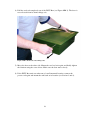
INFU Box
Type 0412A
-Temperature regulation box for IV liquids
User Manual
including;
-Service manual
-Mounting manual
Rx only ’
1
INFU Box is manufactured by Medical Rescue Equipment (MRE) Holding AS
INFU Box bears the
marking and complies with the provisions of the Medical
Device Directive 93/42/EEC
and harmonized standards of the directive.
The Device is also compliant with
the Swedish LVFS 2003:11,
the Norweigan FOR 2005-12-15 nr 1690 and
SS-EN 1789 2007 Medical vehicles and their equipment – Road ambulances
Additionally the device complies with all applicable parts of the standards listed in
Appendix II, Applicable standards.
--------This manual reflects INFU Box, type 0412A.
Revision 1.14
MRE Holding AS
2
Contents
1
General ...................................................................................................................6
1.1
Medical device classification.............................................................................. 6
1.2
Electrical safety classification............................................................................. 6
1.3
Label with technical information ........................................................................ 6
1.4
Intension of device .............................................................................................. 7
2
Meaning of symbols...............................................................................................8
3
Instructions before use ...........................................................................................9
3.1
Notes and warnings............................................................................................. 9
3.2
Contraindications .............................................................................................. 10
3.3
Restrictions regarding temperature ................................................................... 10
3.4
Temperature deviations..................................................................................... 10
3.5
Handling of IV liquid bags ............................................................................... 11
3.5.1
Restrictions for IV liquid vessel and volume............................................ 11
3.5.2
Restrictions for kind of IV liquid.............................................................. 11
3.5.3
Restrictions for procedure/ handling of IV liquid bags ............................ 11
3.6
Noise level ........................................................................................................ 11
4
Environmental requirements ................................................................................12
4.1
Operating........................................................................................................... 12
4.2
Storage/ transport .............................................................................................. 12
5
Electrical ratings ..................................................................................................13
5.1
Voltage guard.................................................................................................... 13
5.2
Fuses ................................................................................................................. 13
5.3
Emission and immunity .................................................................................... 13
6
Use Procedure ......................................................................................................15
6.1
The product and interface ................................................................................. 15
6.2
Quick-guide....................................................................................................... 15
6.3
Mini manual ...................................................................................................... 15
6.4
Control panel..................................................................................................... 16
6.4.1
Power switch ............................................................................................. 16
6.4.2
Display ...................................................................................................... 16
6.4.3
Diodes ....................................................................................................... 17
6.4.4
Control buttons.......................................................................................... 17
6.5
Errors and warnings .......................................................................................... 17
6.5.1
High temperature alarm ............................................................................ 17
6.5.2
Sensor error alarm..................................................................................... 18
6.6
Temperature regulation with INFU Box........................................................... 19
6.6.1
Settings...................................................................................................... 20
7
Trouble Shooting .................................................................................................21
7.1
7.2
7.3
Alarm and error message .................................................................................. 21
Display turns blank/ turns off ........................................................................... 21
INFU Box does not start ................................................................................... 21
3
7.4
Slow temperature regulating process ................................................................ 22
8
Maintenance, cleaning and contamination...........................................................22
8.1
Maintenance ...................................................................................................... 22
8.2
Cleaning ............................................................................................................ 23
8.3
Contamination................................................................................................... 23
9
Service and Spare parts ........................................................................................23
10
Recycling Instructions .........................................................................................24
11
Manufacturers contact information......................................................................24
12
Product data sheet ................................................................................................25
Appendix I Technical information and properties of INFU Box.................................26
1
Overview..............................................................................................................26
2
Main components.................................................................................................27
Performance heating process ........................................................................................ 29
3
INFU Box properties............................................................................................30
3.1
Guidance and Manufacturers declaration – Electromagnetic emissions .......... 30
3.2
Guidance and Manufacturers declaration – Electromagnetic immunity.... Error!
Bookmark not defined.
3.3
Guidance and Manufacturers declaration – Electromagnetic immunity.... Error!
Bookmark not defined.
3.4
Guidance and Manufacturers declaration – Electromagnetic immunity.... Error!
Bookmark not defined.
Appendix II Mounting Manual INFU Box .................................................................34
1
Checking the INFU Box ......................................................................................35
2
Door hinge position..............................................................................................35
3
INFU Box location in ambulance vehicle............................................................37
4
Installation of INFU Box in ambulance vehicle ..................................................37
5
Electrical power supply and connection ..............................................................38
Appendix III Service Manual INFU Box.....................................................................40
1
Requirements and Information ............................................................................41
1.1
Requirements .................................................................................................... 41
1.2
Information ....................................................................................................... 41
1.3
Voltage guard / voltage watch .......................................................................... 43
2
Change of fuses....................................................................................................43
3
Maintenance, cleaning and contamination...........................................................44
3.1
3.2
3.3
Maintenance ...................................................................................................... 44
Cleaning ............................................................................................................ 45
Contamination................................................................................................... 45
4
4
Trouble Shooting .................................................................................................46
4.1
Alarm and error message .................................................................................. 46
4.2
Display turns blank/ turns off ........................................................................... 46
4.3
INFU Box does not start ................................................................................... 47
4.4
Slow temperature regulating process ................................................................ 47
5
Recycling instructions..........................................................................................47
6
Service and Spare parts ........................................................................................47
7
6.1
Cable cord ......................................................................................................... 47
Contact information to Manufacturer ..................................................................50
5
1 General
Please read this manual thoroughly before starting to use this equipment.
Federal law restricts this device to sale by or on the order of a physician.
1.1
Medical device classification
Table 1: Medical device classification
Classification
Class I
Class II
EU/ CE-mark
USA/ FDA
1.2 Electrical safety classification
According to IEC 60601-1 Electrical safety; INFU Box is classified as shown in Table 2.
Table 2: Electrical safety classification
Protection against electrical shock
Protection against harmful ingress of water
Classification
Class I
IP20*
*The device has class 2 protection against solid foreign objects and class 0 for water
tightness. The device is protected against solid objects with a diameter of 12.5 (+0.05/-0)
mm and a pressure of 30 N (± 10%) and has no protection against water.
1.3 Label with technical information
On the inside of INFU Box door a label is placed with technical information of the device
(see Figure 1-1).
Figure 1-1: Label with technical information for INFU Box.
6
1.4
Intension of device
The INFU Box is intended for the regulation of temperature of intravenous fluids bags
prior to administration. The device is intended for bags with crystalloid fluids only.
Intended users are health care professionals. The device is intended for use in clinical and
field environments and is intended to be mounted in a ground based field operating
vehicle, such as ambulance or military vehicle.
7
2 Meaning of symbols
Existing symbols on the INFU Box unit are shown in Table 3
Table 3: symbols on the INFU Box.
Symbol
Meaning
CE mark. Indicates that the product complies with the Medical
Device Directive 93/42/EEC.
General warning sign
“Warning!!”, “Caution!” or “Note.”. This symbol indicates need
for extra observance. Consult user manual for further
information.
Consult instructions for use
IP-class. N1 indicates the dust-/sand-tightness (protection against
ingression of dust/sand) of the device, N2 indicates the ability of
the device to withstand intrusion of water (protection against the
ingression of water).
Serial number. A unique number for every manufactured INFU
Box unit. Number can be used for traceability.
Manufacturing date. Indicates the date of manufacture for the
unit.
“ON” (power)
“OFF” (power)
Direct current
Rx only
WEEE symbol. Indicates that the product complies with the
WEEE directive 2002/96/EG (waste electrical and electronic
equipment).
Federal law restricts this device to sale by or on the order of a
physician.
8
3 Instructions before use
The device is only intended to be operated by personnel with medical education that have
read the User Manual. Service and mounting installation for device is only to be
performed by qualified service personnel, according to descriptions in the appended
service and mounting manual.
3.1
Notes and warnings
Warning!
Avoid setting the target temperature to other than approximately the normal body
temperature. The interior temperature will only stabilize around the set target
temperature. (See further information is § 3.3 Restrictions regarding temperature.)
Warning!
Too high target temperatures might be dangerous to the patient.
(See further information in § 3.3 Restrictions regarding temperature)
Warning!
Whenever using a pre-tempered IV liquid bag from INFU Box, verify suitable
temperature by holding bag with bare hands and estimate the bag temperature.
Warning!
The internal temperature indicated on the INFU Box display may differ some degrees
from the actual temperatures in the infusion bags. (See further information in § 3.4
Temperature deviations)
Warning!
INFU Box may not be used more than 10 years after last programming date. Contact
manufacturer for a new product update.
(See further information in § 8.1 Maintenance and the appended Service Manual)
Note.
There might appear warnings messages on the INFU Box display. A description of these
can be found in § 6.5 Errors and warnings.
Note.
INFU Box is only to be used together with a functioning climate system in the
ambulance. (See description in § 6.6)
9
Note.
INFU Box is intended to perform temperature control on 3 IV bags simultaneously, all
bags having the same original temperature. In order to achieve accurate temperature
control, always make sure that the middle shelf carries an IV bag. Make sure the INFU
Box is fully emptied before new IV bags are placed on the shelves. (See description in §
3.5.3)
3.2
•
•
•
•
Contraindications
Do not use device with infusion bags containing blood or other protein based
liquids.
Do not use device outside recommended temperature range.
Do not use device in other environmental situations than those specified in § 4.
Do not use device in other electrical setup than the one specified in § 0.
3.3 Restrictions regarding temperature
The INFU Box is intended to regulate and maintain the temperature of IV liquid. The
operator does this by setting a target temperature on the INFU Box. The device then
adjusts the temperature inside the INFU Box compartment until the set target temperature
is reached and maintains that temperature. Recommended target temperature is normal
body temperature.
Temperatures over body-temperature endeavour the patient-safety, due to the risk of
coagulation and thrombosis or hyperthermia. Too cold temperatures endeavour the
patient-safety due to the risk of hypothermia. To achieve a better control of unwanted
temperature limits the operator can also set an alarm temperature. If the interior
temperature reaches the set alarm temperature the operator is given audible as well as
visual feedback.
The intended use of the INFU Box is to set the target temperature close to normal body
temperature, and the alarm temperature to typically some degrees higher. It is possible to
set both the target temperature and the alarm temperature to other temperatures but this is
NOT RECOMMENDED. The manufacturer takes no responsible for use outside
recommendations.
3.4 Temperature deviations
During a heating process from room temperature, when the device is equipped with 3
bags, the INFU Box display value reaches body-temperature after about 1 hour (if
recommended power supply to the device is provided sufficiently). The display
temperature corresponds to the surface temperature of the IV bag in the middle-shelf. The
core-temperature of the bag can deviate from its surface temperature, and the bag
temperature may also deviate between the bags in different positions in INFU Box.
Longer time of temperature control inside the INFU Box gives less deviation between
bags.
10
During a cooling process the temperature change is not as fast as during warming. As an
example, the cooling of 3 IV bags from +50°C (120°F) down to normal body temperature
typically takes 3 hours.
3.5
Handling of IV liquid bags
3.5.1 Restrictions for IV liquid vessel and volume
-Intended IV liquid bags are soft plastic bags with 1000 ml IV liquid.
-INFU Box is designed to regulate three liquid bags simultaneously.
3.5.2 Restrictions for kind of IV liquid
-This device is intended for use with crystalloid fluids only, such as normal saline and
Ringer’s lactate solutions. Do not warm any proteins based fluids or nutrition in the
device.
-Do not use device to heat blood.
3.5.3 Restrictions for procedure/ handling of IV liquid bags
- Whenever there are bags kept in INFU Box make sure a bag is placed on the middle
shelf (where the temperature sensor is located).
- INFU Box has to be emptied before new bags are mounted. All IV bags mounted have
to have the same original temperature.
- Do not use IV liquid that is blurry or non-transparent!
- Only use new, sealed IV liquid bags (nor earlier used on patients)!
Beside these restrictions, follow the standard handling procedure of IV liquid bags.
3.6 Noise level
The INFU box noise level at 1.0 meter distance is 50-55 dB
11
4 Environmental requirements
4.1 Operating
The device is designed to be operated in a room-tempered environment. The device uses
environmental air to cool down the IV liquid. If during a cooling process the difference
between target temperature and environmental temperature becomes too small, the
cooling process of the INFU Box will be insufficient and the target temperature not
reached.
The manufacturer only takes responsibility for the function of the device when used in
situations which fulfil the conditions of Table 4-I.
Table 4-I Environmental requirements for operation
Ambient temperature:
(In order to work satisfyingly, INFU Box
is not to be used without a climate system
controlled environment)
Relative humidity
(in combination with temperature):
Atmospheric pressure:
15 -30°C (59-86°F)
Room temperature 20±2°C, 30%-75%
RH (64-72°F, 30%-75% RH
Normal atmospheric pressure on ground,
anywhere on earth.
4.2 Storage/ transport
When the INFU Box is not mounted in the vehicle (during storing or transport) the
original packaging shall be used. The manufacturer only takes responsibility for the
function of the device when stored/transported in its original packaging, in situations
which fulfil the conditions of Table 4-II.
Table 4-II Environmental requirements for storage and transport
Ambient temperature:
Relative humidity:
Atmospheric pressure:
-45°C – +70°C, (-49°F - +158°F)
No specifications
Normal atmospheric pressure on ground,
anywhere on earth. If transporting with
flight it is recommended to use a
pressurized cabin.
12
5 Electrical ratings
The INFU Box is intended to be used with 12 V DC (direct current). Max current 16A.
The maximum effect of the device is ~180 W.
5.1 Voltage guard
INFU Box has a built-in voltage guard to prevent the device from emptying the vehicle
battery (for further information see appended Service manual.) If power supply goes
below 11 V, two out of three peltier-elements cut out. The power consumption is reduced
to 30%. The IV liquid is kept at temperature, but warming process is slowed down. When
power supply again exceeds 12.5 V all elements are re-activated.
If power goes lower than 6 V, INFU Box will turn itself off until enough power is
supplied again.
5.2 Fuses
Further information about fuses is found in the appended Service manual. Note! Not to be
changed in field!
5.3 Emission and immunity
The electromagnetic compatibility of the INFU Box has been tested and approved
according to the standard IEC 60601-1-2:2007
13
Table 5-I Performed EMC tests
Emission:
Conducted emission
Radiated emission
Interference immunity:
Electrostatic discharge
Electromagnetic field
Electrical Fast Transient (Burst)
Conducted disturbances, induced by RF-fields
Magnetic field (power-frequency)
A summary of the results of the tests in
14
Table 5-I (and related recommendations) is included in 3INFU Box properties.
For special precautions regarding EMC, the INFU Box shall be installed and put into
service according to the EMC information provided in Appendix I; Technical information
and properties of the INFU Box.
Portable and mobile RF communications equipment can effect medical electrical
equipment such as the INFU Box.
15
6 Use Procedure
6.1 The product and interface
The product is intended to regulate the temperature of IV liquid bags prior to infusion.
The box is electronically regulated to obtain and maintain a preset temperature.
Control panel
Quickguide
Mini manual
Compartment for maximum
3 IV liquid bags of 1000 ml
infusion each
Figure 6-1: INFU Box.
6.2 Quick-guide
There is a Quick-guide that describes how to use INFU Box. The Quick-guide is found in
a pocket inside INFU Box door (see Figure 6-1). The Quick-guide information is also
available in § 6.6 Temperature regulation with INFU Box and § 6.6.1 Settings.
6.3 Mini manual
Inside the INFU Box door, just below the front panel, there is a Settings manual, or Mini
manual, (see Figure 6-1). The Mini manual briefly explains how to set the target
temperature and the alarm temperature.
16
6.4 Control panel
The control panel (see Figure 6-2) is the interface where the user can set target
temperature, alarm temperature and get feedback on the temperature control process.
Display
Indicator for reached target temperature
Control buttons
Power switch
Warning for reached alarm temperature
Figure 6-2: Product interface.
6.4.1 Power switch
Above and below the power switch there are symbols to show if the INFU Box is turned
on or off. See below.
“ON” (power)
“OFF” (power)
6.4.2 Display
When the INFU Box is turned on the display shows a starting message consisting of the
unit number.
The display shows the set target temperature to the left and the actual temperature to the
right. An arrow in the display indicates if the temperature is rising or sinking, (see Figure
6-3 and Figure 6-4 for example). The temperature can be displayed in Celsius or in
Fahrenheit. For information on how to change between °C and °F, see instructions in §
6.6.1 Settings.
Figure 6-3: Example of display with temperature in Celsius.
17
Figure 6-4: Example of display with temperature in Fahrenheit
6.4.3 Diodes
Diode 1, “Indicator for reached target temperature”, is lit (with an orange light) when
INFU Box reaches target temperature (corresponding to the surface temperature on IV
bag on middle shelf).
Diode 2, “Warning for reached alarm temperature”, is lit (with an orange light) when
the set alarm temperature is exceeded. There will also be an audible alarm. For further
information; see 6.5 Errors and warnings.
6.4.4 Control buttons
The control buttons under the display are used to set the target and alarm temperatures,
for changing between temperature units and for shutting down the audible feedback when
the alarm temperature is reached (however, Control button 2 has no operator function).
When setting the temperature the device gives audible feed-back in form of beep signals.
For further information about the settings, see § 6.6.1 Settings.
6.5
Errors and warnings
6.5.1 High temperature alarm
If INFU Box exceeds the set alarm temperature, diode 2 is lit and an audible alarm is
heard. The display also shows a warning message: “ALARM” and shows the set alarm
temperature.
The audible alarm can be silenced by pushing one of the control buttons 1-4 (under the
display, see Figure 6-5)
Diode 2 maintains lit and the error message on the display remains until measured INFU
Box temperature has gone below the set alarm temperature.
1
2
3
4
Figure 6-5: Press one of the buttons # 1-4 to quiet the audible alarm.
18
6.5.2 Sensor error alarm
If the INFU Box display shows “SENSOR ERROR” this is an indication of that
something has gone wrong with the sensor regulation. After displayed message all
temperature regulation will stop. In order to re-set the functioning switch off the INFU
Box, wait 10 seconds and then turn it on again. If the “SENSOR ERROR” message still
is shown again change to another INFU Box and contact the manufacturer.
19
6.6
Temperature regulation with INFU Box
1. In climate controlled area:
2. Set/ check target- & alarm
temperature
(according to instructions in Mini manual
and/ or § 6.6.1Settings in User manual).
Turn INFU Box on with the power button.
1
2
3
4
Recommended temperatures;
Target temperature: 38°C / 100.4°F.
Alarm temperature: 42°C/ 107.6°F.
3. Insert 3 IV bags in INFU Box.
4. Close door & wait for target
temperature to be reached.
→ Always start with the middle shelf.
(This is indicated by the orange diode next to
the display).
5. Bring out IV bag with reached target
temperature.
6. Verify that temperature is ok by
holding IV bag with bare hands.
- Always double-check the display temperature
- Always leave middle bag to last.
IV bag is now ready to be used in infusion
treatment.
If INFU Box is left ON in a non-running vehicle, there is a risk of emptying the vehicle battery!
20
6.6.1 Settings
Below follows a description of how to regulate target temperature, alarm temperature and
changing between Celsius and Fahrenheit with the control buttons.
Setting target temperature
1. Press the (1)-button
4 seconds
for entering
programming
mode
2
1
2. Press the (4)-button
for adjusting
temp up
3
4
2
2
3
4
3
4
3
4
3
4
4. Press the (1)-button
for exit
3. Press the (3)-button
for adjusting
temp down
1
1
3
1
4
2
Setting the alarm temperature
1. Press the (1) and (4)-button
4 seconds
for entering
programming
mode
2
3
1
4
2. Press the (4)-button
for adjusting
temp up
3. Press the (3)-button
for adjusting
temp down
4. Press the (1)-button
to exit
1
2
3
1
1
4
21
2
2
Changing between °C and °F
1. Press the (1), (3) and (4)
button and hold
4 seconds
to enter
2
3
1
programming
mode.
3. Or press the (3)button for
switching
between
°C and °F.
1
2. Press the (4)-button
for switching
between
°C and °F.
4
1
2
3
4
3
4
4. Press the (1)-button
to exit.
2
3
1
4
2
7 Trouble Shooting
Below are a number of problems that may arise with INFU Box described. In case of
further problems; please contact manufacturer.
7.1 Alarm and error message
In normal use the only alarm message on the device is indication that internal temperature
reaches the pre-set alarm temperature. This is indicated by a display-message, a diode
light and an audible beep signal. See § 6.5 Errors and warnings.
7.2 Display turns blank/ turns off
If the supplied voltage source goes lower than 6 V, the INFU Box will turn itself off until
enough voltage is supplied again (over 6 V).
If the display is blank it can also be a sign that the main fuse is broken. Service personnel
is then required.
7.3 INFU Box does not start
If INFU Box does not start at all;
• Check that contacts and cables are connected and that power is supplied from
external source.
• If the INFU Box has been exposed to extreme temperatures, leave the unit in
room temperature for 10 minutes and then try to start it again.
• If none of above mentioned steps works service personnel authorized by the
manufacturer should be contacted.
22
7.4 Slow temperature regulating process
There are three heating elements in the INFU Box for temperature regulation. To prevent
the vehicle battery from emptying the INFU Box has a built-in voltage guard. If power
supply goes below 11 V, two out of three heating elements cut out. IV liquid is kept in
temperature, but warming process is slowed down. When the voltage supply becomes
12.5 V or higher, all elements are again activated.
If the process to reach target temperature is slower than normal, the power supply can
have dropped below 11 V or a peltier element fuse may have blown.
For each of the three heating elements there is a fuse. If a fuse blows the corresponding
element will stop the heating process. Only contact service personnel authorized by the
manufacturer for changing a blown fuse.
If the cooling regulation process is slow make sure that the environmental temperature is
low enough to cool down the interior temperature. The INFU Box is designed to use the
environmental air for cooling and thus the compartment inside the vehicle should be close
to normal room temperature.
8 Maintenance, cleaning and contamination
8.1 Maintenance
For INFU Box to function fully the maintenance procedure included in the appended
service manual should be performed at least once a year.
Daily; confirm the regulation temperature of bags that are stored inside INFU Box
(maintained at body-temperature) by temporarily holding bags in hands. The bags should
feel warm, but not uncomfortable in temperature.
Weekly; check IV Liquid fluids so that solution clarity is normal that and expiration date
has not been exceeded.
Yearly (or at the designated service intervals); maintenance routines described in the
appended service manual will be performed by service personnel authorized by the
manufacturer. 10 years after the latest programming of the INFU Box processor the
manufacturer should be contacted for a product update.
23
8.2
•
•
•
•
Cleaning
When cleaning the INFU Box on the door and front, use a moist cloth and any
typical nonabrasive cleaning detergents available for households. If contaminated;
use a disinfectant cleaning detergent, such as DAX Ytdesinfektion Plus (Alcohol
45vol%) or Gigasept Instru AF (3% solution). Apply according to detergent
product specification.
Do not soak the unit. Be especially careful around air inlets (see Figure 8-1). No
liquid whatsoever is allowed to penetrate into the unit.
For cleaning the interior compartment of the device use the same procedure as on
outside. At the bottom of INFU Box a small brush is required, for example a
toothbrush, to be able to clean below bottom shelf.
If IV bag has leaked, thorough cleaning may be required due rests from NaClsolutions.
8.3 Contamination
-If there is danger of
contamination of the
device, clean the INFU
Box with disinfectant
detergent according to
instructions above.
In- and outlet
for air
INFU Box does not
guarantee protection
from blood infections.
Figure 8-1: INFU Box.
9 Service and Spare parts
INFU Box cable cord is a spare part and can be exchanged by authorized service
personnel. The INFU Box door is reversible (mounted on the left or the right side) and
changing the hinge location shall also be performed by authorized service personnel. For
further information, se appended Service Manual or contact manufacturer.
Detailed service instructions are found in the attached Service manual.
24
10 Recycling Instructions
When disposed, INFU Box shall be de-mounted and distributed to appropriate waste
management.
All polymeric materials shall be wasted according to national recommendations.
All electronic parts shall be de-mounted and returned to national authorities
responsible for electronic waste.
Other parts shall be recycled according to national recommendations.
All packaging material shall be wasted according to national recommendations.
All materials can be sent to manufacturer for recycling, see contact information below.
11 Manufacturers contact information
MRE (Medical Rescue Equipment) Holding AS
Postboks 186
3901 Porsgrunn, Norway
Phone: +47 90610425
Fax: +47 35515014
E-mail: [email protected]
Homepage: www.mre-holding.com
25
12 Product data sheet
Company name:
Product name:
Model designation:
Description:
Medical Rescue Equipment (MRE) Holding AS
INFU Box
0412A (Military IV warmer, A = first release version)
INFU Box is a temperature regulation box for bags with
infusion liquid. The device is intended to be used mainly in
acute medicine and military fields. The box is intended to be
mounted in a vehicle (for example ambulance or military
vehicle).
The device is electrically regulated and intended to obtain
and maintain correct temperature (body temperature) for bags
with IV liquid, before infusion. The box has room for three
IV bags of 1000 ml liquid each.
Size:
Drive:
Target temperature and high-temperature alarm can be
manually regulated. Recommendations for target temperature
(because of intended use) are body-temperature. Alarm
temperature is set to warn before temperature is dangerously
high.
Height: about 545 mm.
Width: about 500 mm.
Depth: about 175 mm.
Weight: 9 kg for INFU Box only
and 11 kg for INFU Box with packaging
12V DC, (max 180W).
Figure 12-1: INFU Box.
26
Appendix I Technical information and properties of INFU Box
1 Overview
An overview of the INFU Box is shown in Figure TI 1.
Front folio
Front cover for
electronics
Label 12 V DC
Door
Heating/cooling housing for fins
Label mini guide
Power
cable
Label
(tech data/
serial no)
Label MRE
company
Rack
(shelf section)
Figure TI 1: Overview of INFU Box and its components.
27
Cabinet
2 Main components
The main components of the INFU Box type 0412 are listed in Table TI 1.
The main system function is shown in
Figur TI 1:. Circuit diagrams are available from the manufacturer only on demand, and
only if necessary for performing the service as intended in the service manual only.
Table TI 1: Main components of INFU Box
Description
Electronics unit
PCB Infusion heat controller
Voltage Guard
Heat sensor
Heat/cool unit
28
Article no
299.000122
382.000250
382.000252
382.000251
299.000120
Figur TI 1: Overview of the electronics system.
29
The main mechanical function of the heating/cooling system is shown in Figure TI 2. The
peltier-elements are controlled by the electronics to produce a temperature difference
between the inner and external airflow. During heating of the inner compartment the hot
sides of the peltier-elements are facing the heat flanges of the inner airflow. During a
cooling process the voltage potential is reversed over the peltier-element, thus cooling the
side in contact with the inner air heat flanges.
Figure TI 2: Airflow in INFU Box.
The main system is powered by a 12 V DC source. The Fan (outside) drives the external
airflow in the upper part of the INFU Box, and the Fan (inside) drives the internal
airflow. The Infusion heat controller regulates the power through the peltier-elements,
and also controls the LCD-display and information feedback to the user. The peltierelement regulation is based on information from the Temperature sensor.
The Voltage guard controls how much power the INFU Box uses, based on measuring
the supply voltage level. If the voltage gets lower (for example from a weak vehicle
battery) the Voltage guard shuts down 2 out of 3 peltier-element in order not to empty the
battery. The full capacity is restored when the supply voltage level returns to normal.
30
INFUBox environment temp
Performance heating process
The figure below shows the time to heat three IV bags from room temperature of 24 to a
body temperature of 38ºC. With an environmental temperature of 24 ºC the heating time
is approximately 1 hour. Following a 24-hour period of INFU Box storage in -45 ºC, the
heating time is approximately 2 hours and 15 minutes (Note: the warming should always
be done in a room-tempered environment, for example in a climate-controlled vehicle).
24 °C
-45 °C
0
20
40
60
80
100
120
140
160
Minutes to reach body temp. (infusion bags initially room tempered)
Figure TI 3: Time for three Infusion bags to reach body temperature in INFU Box starting from
room tempered state. The upper bar shows the time when the INFU Box was stored in room
temperature 24 hours before warming; and the lower bar shows the warming time after 24 hours of
storage in -45 °C.
31
3 INFU Box properties
3.1
Guidance and Manufacturers declaration – Electromagnetic emissions
Table TI 2 Guidance Electromagnetic emissions
Guidance and Manufacturers declaration – Electromagnetic emissions
The INFU Box Type 0412A is intended for use in the electromagnetic environment specified
below. The customer or the user of the INFU Box should assure that it is used in such an
environment.
Emissions test
Compliance
Electromagnetic environment - guidance
The INFU Box Type 0412A uses RF energy
RF emissions
only for its internal function. Therefore, its
Group 1
RF emissions are very low and are not
CISPR 11
likely to cause any interference in nearby
electronic equipment.
The INFU Box Type 0412A is suitable for
use in all establishments other than
RF emissions
Class B
domestic and those directly connected to
the public low-voltage power supply
CISPR 11
network that supplies buildings used for
domestic purposes.
Harmonic emissions
Not Applicable
IEC 61000-3-2
Voltage fluctuations/
flicker emissions
Not Applicable
IEC 61000-3-3
3.2
Guidance and Manufacturers declaration – Electromagnetic immunity
Table TI 3 Guidance Electromagnetic immunity
Guidance and Manufacturers declaration – Electromagnetic immunity
The INFU Box Type 0412A is intended for use in the electromagnetic environment specified
below. The customer or the user of the INFU Box Type 0412A should assure that it is used in
such an environment.
Immunity test
IEC 60601
test level
Compliance
level
Electrostatic
discharge (ESD)
±6 kV contact
±6 kV contact
±8 kV air
±8 kV air
IEC 61000-4-2
32
Electromagnetic environment guidance
The INFU Box Type 0412A is
intended to be mounted in a
ground based field operating
vehicle, such as ambulance or
military vehicle compliant with the
requirements of SS-EN
1789_2007.
The INFU Box Type 0412A is
intended to be mounted in a
ground based field operating
vehicle, such as ambulance or
military vehicle. Hence the mains
power quality should be that of
such a vehicle.
Electrical fast
transient/burst
±2 kV for power
supply lines
±2 kV for power
supply lines
IEC 61000-4-4
±1 kV for
input/output
lines
Not Applicable
Surge
±1 kV line(s) to
line(s)
Not Applicable
The INFU box is DC powered.
Not Applicable
The INFU box is DC powered.
IEC 61000-4-5
±2 kV line(s) to
earth
Voltage dips, short
interruptions and
voltage variations
on power supply
input lines
IEC 61000-4-11
<5 % UT
(>95 % dip in
UT) for 0,5
cycle
40 % UT
(60 % dip in UT)
for 5 cycles
70 % UT
(30 % dip in UT)
for 25 cycles
<5 % UT
(>95 % dip in
UT) for 5 s
Power frequency
(50/60 Hz)
magnetic field
3 A/m
3 A/m
The INFU Box Type 0412A is
intended to be mounted in a
ground based field operating
vehicle, such as ambulance or
IEC 61000-4-8
military vehicle. Hence the power
frequency magnetic fields should
be at levels characteristic of such
a vehicle.
NOTE UT is the a.c. mains voltage prior to application of the test level.
33
3.3
Guidance and Manufacturers declaration – Electromagnetic immunity
Table TI 4 Guidance Electromagnetic immunity
Guidance and Manufacturers declaration – Electromagnetic immunity
The INFU Box Type 0412A is intended for use in the electromagnetic environment specified
below. The customer or the user of the INFU Box Type 0412A should assure that it is used in
such an environment.
Immunity test
IEC 60601
test level
Compliance
level
Electromagnetic environment guidance
Portable and mobile RF
communications equipment should
be used no closer to any part of the
INFU Box Type 0412A, including
cables, than the recommended
separation distance calculated from
the equation applicable to the
frequency of the transmitter.
Conducted RF
IEC 61000-4-6
3 Vrms
150 kHz to 80
MHz
10 Vrms
d = 0,35 P
d = 0,175 P
Radiated RF
electromagnetic
fields
IEC 61000-4-3
3 V/m
80 MHz to 2,5
GHz
20 V/m
(According to
requirements of
SS-EN
1789_2007)
d = 0,35 P
(80 MHz to 800 MHz)
(800 MHz to 2,5 GHz)
Where P is the maximum output
power rating of the transmitter in
watts (W) according to the
transmitter manufacturer and d is
the recommended separation
distance in metres (m).
Field strengths from fixed RF
transmitters, as determined by an
a
electromagnetic site survey,
should be less than the compliance
b
level in each frequency range.
Interference may occur in the
vicinity (surroundings) of equipment
marked with the following symbol:
NOTE 1 At 80 MHz and 800 MHz, the higher frequency range applies.
NOTE 2 These guidelines may not apply in all situations. Electromagnetic propagation is
affected by absorption and reflection from structures, objects and people.
34
a
Field strengths from fixed transmitters, such as base stations for radio (cellular/cordless)
telephones and land mobile radios, amateur radio, AM and FM radio broadcast and TV
broadcast cannot be predicted theoretically with accuracy. To asses the electromagnetic
environment due to fixed RF transmitters, an electromagnetic site survey should be considered.
If the measured field strength in the location in which the INFUBox Type 0412A is used exceeds
the applicable RF compliance level above, the INFUBox Type 0412A should be observed to
verify normal operation. If abnormal performance is observed, additional measures may be
necessary, such as re-orienting or relocating the INFUBox Type 0412A.
b
Over the frequency range 150 kHz to 80 MHz, field strengths should be less than 10 V/m.
3.4
Guidance and Manufacturers declaration – Electromagnetic immunity
Table TI 5 Guidance Electromagnetic immunity
Recommended separation distances between portable and mobile RF communications
equipment and the InfuBOX for ME EQUIPMENT and ME SYSTEMS that are not LIFESUPPORTING
The INFU Box Type 0412A is intended for use in an electromagnetic environment in which
radiated RF disturbances are controlled. The customer or the user of the INFU Box Type
0412A can help prevent electromagnetic interference by maintaining a minimum distance
between portable and mobile RF communications equipment (transmitters) and the INFU Box
Type 0412A as recommended below, according to the maximum output power of the
communications equipment.
Rated maximum
Separation distance according to frequency of transmitter [m]
output power of
transmitter
[W]
150 kHz to 80 MHz
80 MHz to 800 MHz
800 MHz to 2,5 GHz
d = 0,35 P
d = 0,175 P
d = 0,35 P
0.01
0.035m
0.018m
0.035m
0.1
0.11m
0.055m
0.11m
1
0.35m
0.18m
0.35m
10
1.1m
0.55m
1.11m
100
3.50m
1.8m
3.50m
For transmitters rated at a maximum output power not listed above, the recommended
separation distance d in metres (m) can be estimated using the equation applicable to the
frequency of the transmitter, where P is the maximum output power rating of the transmitter in
watts (W) according to the transmitter manufacturer.
NOTE 1 At 80 MHz and 800 MHz, the separation distance for the higher frequency range
applies.
NOTE 2 These guidelines may not apply in all situations. Electromagnetic propagation is
affected by absorption and reflection from structures, objects and people.
35
Appendix II Mounting Manual INFU Box
INFU Box
Type 0412A
-Temperature regulation box for IV liquids
Mounting Manual
NOTE: mounting is only to be made by personnel authorized by
the manufacturer, which also have authorization to perform
electrical installations in ambulance vehicles.
36
1 Checking the INFU Box
After the INFU Box is unpacked control the unit for any visual damage. If any visual
damage is recognized, please notify your local supplier immediately.
2 Door hinge position
The door hinge position is left handed (as viewed towards the front panel) if not agreed
otherwise according to the purchase order.
If the door hinge position needs to be changed (from left to right or vice versa) this
should be done by designated service personnel. The following procedure describes the
change of door position.
1) If mounted in a vehicle, remove the INFU Box out the wall frame and disconnect
the power cord.
2) Unscrew the four screws that hold the Quick Guide plate (on the inside of the
door), turn the plate upside down and re-mount it using the same screws.
3) At the bottom of the INFU Box (below the hinge axis) locate the steel rod and
unscrew the rod using a screwdriver (see Figure MM 1).
Figure MM 1: Unscrew the steel rod axis (the picture shows a right-hand side hinge location).
37
4) Pull the steel rod completely out of the INFU Box (see Figure MM 2). The door is
now released from its former hinge axis.
Figure MM 2: Removal of door hinge axis.
5) Move the door to the other side. Mount the steel rod axis again and finally tighten
the fixation using the screw driver. Make sure the door moves freely.
6) If the INFU Box unit was taken out of a wall-mounted location, connect the
power cord again and mount the unit back at its location (see Section 3 and 4).
38
3 INFU Box location in ambulance vehicle
When the location for installation of the INFU Box is determined, please note the
following requirements prior to installation;
1) Free depth behind the inner wall to be at minimum 170 mm (7 inch).
2) Ensure that the door may be opened without interfering with existing equipment
or equipment to be installed.
4 Installation of INFU Box in ambulance vehicle
1) Mark the opening area to be removed according to the following dimensions (see
Figure MM 3):
Opening height : 497 mm
Opening width: 452 mm
Figure MM 3: Opening dimensions of wall opening.
2) Cut the area to be removed with an electrical saw or similar.
3) Place the INFU Box into the opening and make sure the dimensions are correct.
4) Mark the holes for screws in the wall using the premade holes in the INFU Box
frame as a template. Remove the INFU Box and drill ∅ 3 mm holes through the
39
marks on the wall. These holes will now act as positioning holes for the screws.
5) Connect the INFU Box power supply according to the following sections.
5 Electrical power supply and connection
Power requirement:
The INFU Box is engineered for a power requirement supply of 12 V DC from the
vehicle (20A fuse). Max current 16A.
If any other voltage is to be connected, it is mandatory to install a DC converter between
the existing power source and the INFU Box.
1) Mount the Power Connector cable at the top connector location. Make sure the
red dot of the connector orients towards the red dot at the insertion (see Figure
MM 4).
Figure MM 4: Mounting the Power Connector to the INFU Box.
2) Connect the 12 V DC positive power supply (+) to the cable end marked (+) and
the negative (-) to the cable end marked (-). For max fuse see table below.
Table MM 1; Fuses of the INFU Box
Number
Main Fuse
F1: FST6.3X32 (20 A)
Fuses Voltage Guard Circuit Board
F1: T1A 250V (1 A No.372K/TR5)
F2-F4: T5A 250V (5 A No.372K/TR5)
1
1
4
40
3) For testing the unit, please turn on the switch located at the upper right on the
front panel. The INFU Box display shows the start-up message. If the INFU Box
does not start, please check the power supply again. If the INFU Box still not
operates contact the manufacturer.
4) After positive function test, mount the INFU Box back in the designated location
in the panel. Make sure that the power cable is not jammed or stressed. Fixate the
INFU Box to the panel using 8 screws of appropriate sizes.
41
Appendix III Service Manual INFU Box
INFU Box
Type 0412A
-Temperature regulation box for IV liquids
Service Manual
Recycling instructions
Cleaning and contamination
42
1 Requirements and Information
1.1 Requirements
Service on this device is only to be performed by service personnel authorized by the
manufacturer. Furthermore, these personnel must be authorized to perform electrical
installations in the intended ambulance vehicles.
1.2 Information
The position of the door can be changed (left or right hinge location). The following
procedure describes the change of door position.
1) If mounted in a vehicle, remove the INFU Box out the wall frame and disconnect
the power cord.
2) Unscrew the four screws that hold the Quick Guide plate (on the inside of the
door), turn the plate upside down and re-mount it using the same screws.
3) At the bottom of the INFU Box (below the hinge axis) locate the steel rod and
unscrew the rod using a screwdriver (see Figure SM 1).
Figure SM 1: Unscrew the steel rod axis (the picture shows a right-hand side hinge location).
4) Pull the steel rod completely out of the INFU Box (see Figure SM 2). The door is
now released from its former hinge axis.
43
Figure SM 2: Removal of door hinge axis.
5) Move the door to the other side. Mount the steel rod axis again and finally tighten
the fixation using the screw driver. Make sure the door moves freely.
6) If the INFU Box unit was taken out of a wall-mounted location, connect the
power cord again and mount the unit back at its location.
44
1.3 Voltage guard / voltage watch
In order not to discharge the battery of a non-running ambulance vehicle, the INFU Box
is equipped with a voltage guard. The unit is designed to work at a nominal voltage of 12
V DC. If the voltage source drops below 11 V the power consumption goes down. The
INFU Box controls this by cutting out 2 of 3 peltier-elements.
All peltier-elements will again be activated if the source voltage reaches higher than 12.5
V, or if the INFU Box is shut off and then restarted while connected to an accurate 12 V
DC source.
If the voltage source should go even further down below 6 V the INFU Box shuts down
completely.
2 Change of fuses
Fuses shall not be changed unless there is a full service/test facility available.
Table SM 1; Fuses of the INFU Box
Number
Main Fuse
F1: FST6.3X32 (20 A)
Fuses Voltage Guard Circuit Board
F1: T1A 250V (1 A No.372K/TR5)
F2-F4: T5A 250V (5 A No.372K/TR5)
1
1
4
45
3 Maintenance, cleaning and contamination
3.1 Maintenance
For INFU Box to function fully the following procedure should be performed at least
once a year;
a.) Cleaning:
Clean INFU Box according to the description in the next section.
b.) Ocular inspection:
Do an ocular check of INFU Box and see that no rust or unsmooth-surfaces are
discovered.
c.) Check fuses:
-Turn INFU Box on. If display and diodes are working, the main fuse is ok. If
normal heating times also have been reported the voltage guards are also OK.
(Otherwise see §4 Trouble shooting.)
d.) Front panel:
-Check that the foil of the front panel is intact.
-Try pressing each regulation button and check that they are working intact.
-Check that the diodes (no.1, no.2 and power-button) are working.
-Check that all elements of the display are intact (that every letter/ number can be
read).
e.) Check that INFU Box is robustly mounted in vehicle (may have to be improved
because of transport-induced mechanical stress).
f.) Check that shelves inside INFU Box, door and other loose parts are robustly
mounted.
g.) Check that the alarm-function works (set a low target temperature to save time,
and then set an even lower alarm temperature). After some time, the alarmfunction should give an audible alarm and indication on diode no. 2.
h.) Check that reached target temperature is indicated by diode no.1 (set a low target
temperature to save time).
i.) Confirm that the display temperature of the INFU Box roughly correspond to the
expected temperature of the liquid bags. For example, this can be made by placing
new bags in the INFU Box, and after some minute compare the displayed
temperature with what could be expected from the non-heated bags.
46
j.) Remember to re-set target temperature and high-temperature value to desired
values after maintenance procedure.
NOTE: 10 years after the latest programming of the INFU Box processor the
manufacturer should be contacted for a product update.
3.2
Cleaning
•
•
•
•
When cleaning the INFU Box on the door and front, use a moist cloth and any
typical nonabrasive cleaning detergents available for households. If contaminated;
use a disinfectant cleaning detergent, such as DAX Ytdesinfektion Plus (Alcohol
45vol%) or Gigasept Instru AF (3% solution). Apply according to detergent
product specification.
Do not soak the unit. Be especially careful around air inlets (see Figure SM 3). No
liquid whatsoever is allowed to penetrate into the unit.
For cleaning the interior compartment of the device use the same procedure as on
outside. At the bottom of INFU Box a small brush is required, for example a
toothbrush, to be able to clean below bottom shelf.
If IV bag has leaked, thorough cleaning may be required due rests from NaClsolutions.
3.3 Contamination
-If there is danger of contamination of the device, clean INFU Box with disinfectant
detergent according to instructions above.
47
Air in- and
outlet
Figure SM 3: Air inlet and outlet of INFU Box.
4 Trouble Shooting
Below are a number of problems that may arise with INFU Box described. In case of
further problems; please contact manufacturer.
4.1 Alarm and error message
In normal use the only alarm message on the device is indication that internal temperature
reaches the pre-set alarm temperature. This is indicated by a display-message
“ALARM”, a diode light and an audible beep signal.
If the INFU Box display shows “SENSOR ERROR” this is an indication of that
something has gone wrong with the sensor regulation. After displayed message all
temperature regulation will stop. In order to re-set the functioning switch off the INFU
Box, wait 10 seconds and then turn it on again. If the “SENSOR ERROR” message still
is shown again contact the manufacturer.
4.2 Display turns blank/ turns off
If the supplied voltage source goes lower than 6 V, the INFU Box will turn itself off until
enough voltage is supplied again (over 6 V).
If the display is blank it can also be a sign that the main fuse is broken, chapter 4.3 below.
48
4.3 INFU Box does not start
If the INFU box does not start at all:
Check the power cable and that the 12V DC is present.
If power is ok, the problems can be one of the following:
1. Main fuse blown, probably caused by an internal short circuit.
2. The 100 dgr. thermo switch is released due to high temperature on the heat sink.
Probable caused by stopped fan(s) or faulty electronics.
Any of these causes are reason to have a complete check out of the equipment. Changing
the main fuse or resetting the thermo switch can cause more damage to the INFU box.
Call for proper service or contact the manufacturer.
4.4 Slow temperature regulating process
If the process to reach the target temperature is slower than normal, the power supply is
less than 11V or a fuse for one or more of the heating/cooling elements are blown.
The INFU box is still operational, but change the unit at first possibility.
Do not attempt to change the fuses, as the heating element can be destroyed.
If the cooling regulation process is slow make sure that the environmental temperature is
low enough to cool down the interior temperature. The INFU Box is designed to use the
environmental air for cooling and thus the compartment inside the vehicle should be close
to normal room temperature.
5 Recycling instructions
When disposed, INFU Box shall be de-mounted and distributed to appropriate waste
management.
All polymeric materials shall be wasted according to national recommendations.
All electronic parts shall be de-mounted and returned to national authorities
responsible for electronic waste.
Other parts shall be recycled according to national recommendations.
All packaging material shall be wasted according to national recommendations.
All materials can be sent to manufacturer for recycling, see contact information below.
6 Service and Spare parts
6.1 Cable cord
The INFU box shall be connected to a 12V battery using the power supply cord. If
needed, this power cord can be replaced by service personnel. Only use original power
cords from the manufacturer.
49
When changing the power cord, take the cabinet first out of the panel wall in the
ambulance vehicle. To dismount the old cord from the socket, lift the metallic sleeve as
shown in Figure SM 4. Remove the other end from the 12 V DC supply and connect the
new cord to the same power source (see Figure SM 5; connect the positive supply + to the
cable end marked +, and the negative – supply to the cable end marked –). When
mounting the new cord on to the INFU Box make sure the red marking is placed in line
with the red marking of the socket (see Figure SM 6).
Figure SM 4: Lift the sleeve to dismount the cord from the socket
Figure SM 5: The end of the power cable shall be mounted to the vehicle 12 V DC power supply.
50
Figure SM 6: Place the red marking on the cord in line with the red marking on socket
51
7 Contact information to Manufacturer
MRE (Medical Rescue Equipment) Holding AS
Postboks 186
3901 Porsgrunn, Norway
Phone: +47 90610425
Fax: +47 35515014
E-mail: [email protected]
Homepage: www.mre-holding.com
52