1
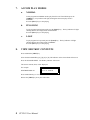
12843 Foothill Blvd.,
Suite D
Sylmar, CA 91342
818 898 3380 voice
818 898 3360 fax
www.dnfcontrols.com
Model No. ST320-X
SHOTBOX
For ACCOM Attache, 2Xtreme
USER MANUAL
1
ST320-X User Manual
Table of Contents
1.
REVISION HISTORY
3
2.
INSTALLATION
3
3.
DESCRIPTION
3
4.
SHOTBOX DISPLAY
3
5.
BANK AND SHOTKEY INDICATORS
3
6.
CONTROL KEYS
a.
MARK IN TIME
b.
MARK OUT TIME
4
4
4
7.
ACCOM PLAY MODES
a.
NORMAL
b.
PING-PONG
c.
LOOP
5
5
5
5
8.
VIEW SHOTKEY CONTENTS
5
9.
SPECIFICATIONS
ST320 (SHOTBOX)
RS422 SERIAL CONNECTOR
POWER CONNECTOR
6
6
6
6
10.
DNF CONTROLS LIMITED WARRANTY
7
Manual Version..........………………................. 2.1 010604
Document No..................…......... ST320-X User Manual.doc
2
ST320-X User Manual
1.
REVISION HISTORY
010604 Rev. 2.1
2.
Company header information revised.
Reformatted.
Added DNF Controls Limited Warranty.
INSTALLATION
a.
Connect a standard 9-pin, RS422 cable from the connector labeled OUTPUT on the rear
of the SHOTBOX, to the RS422 REMOTE connector on the ACCOM DDR.
b.
Connect the POWER SUPPLY to the POWER connector on the rear of the ST320
SHOTBOX. Plug the POWER SUPPLY into a wall outlet, 90 VAC to 240 VAC.
Installation is complete.
3.
DESCRIPTION
Press the desired BANK and SHOTKEY to cause the ACCOM to search to a specific time.
Press [PLAY] to play from the IN time to the OUT time and stop.
Press [STOP] to stop the DDR.
4.
SHOTBOX DISPLAY
The top line of the display shows the BANK and SHOTKEY location of the last pressed Shotkey.
The bottom line of the display shows the contents of the last selected Shotkey.
For Example:
5.
Bank= 2 SW= 30
01:00:00:00
BANK and SHOTKEY INDICATORS
The BANK key indicators show the currently selected bank.
The SHOTKEY indicator shows the last Shotkey, to either Mark a time, View a time or Search to
a time.
For example:
Press BANK 3. The BANK 3 indicator will turn on.
Press Shotkey 42. The SHOTKEY 42 indicator will on.
Only one BANK and SHOTKEY indicator are on at a time. Sometimes one BANK indicator will
be on and all the SHOTKEY indicators will be off.
The BANK and SHOTKEY indicators that are currently on show the location of the last selected
Shotkey.
3
ST320-X User Manual
6.
CONTROL KEYS
The [PLAY] and [STOP] keys control the ACCOM DDR.
Pressing the [PLAY] key puts the DDR into PLAY mode.
Pressing the [STOP] key puts the DDR into STOP mode.
a.
MARK IN TIME
Press and hold the [IN] key.
Select the desired BANK by pressing BANK key [1], [2], [3] or [4].
Press the desired Shotkey.
The display will display the marked time for 2 seconds.
Release the [IN] key.
b.
MARK OUT TIME
Press and hold the [OUT] key.
Select the desired BANK by pressing BANK key [1], [2], [3] or [4].
Press the desired Shotkey.
The display will display the marked time for 2 seconds.
Release the [OUT] key.
4
ST320-X User Manual
7.
ACCOM PLAY MODES
a.
NORMAL
To Play Segment in NORMAL mode (play from IN to OUT and STOP) press the
[NORM] key. Key indicator will light, showing that the current play mode is
NORMAL.
Press the [PLAY] key to start playing.
b.
PING-PONG
To play Segment in Ping-Pong mode press the [PPNG] key. The key indicator will light
showing that the current play mode is PING-PONG.
Press the [PLAY] key to start playing
c.
LOOP
To play Segment in Loop mode press the [LOOP] key. The key indicator will light
showing that the current play mode is NORMAL.
Press the [PLAY] key to start playing.
8.
VIEW SHOTKEY CONTENTS
Press and hold the [VIEW] key.
Select the desired BANK key [1], [2], [3] or [4]. The indicator on the selected bank will turn on.
Press the desired SHOTKEY. The Shotkey indicator will turn on.
The current contents (time) will be displayed.
For example:
SHOTBOX DISPLAY:
IN: 01:00:00:00
OUT: 01:10:00:00
Press another Shotkey, to view its contents.
Release the [VIEW] key at any time when done.
5
ST320-X User Manual
9.
SPECIFICATIONS
ST320 (SHOTBOX)
Power
90 VAC to 265 VAC adapter supplied with IEC connector
Size
(L” x W” x H”) 12” x 6” x 1.5” (front) 3.0” (rear)
Weight
4 lbs.
Real Panel Connectors
Power ........................ DB9M
OUTPUT ........…....... DB9F
Display
Easy to read 2-line, backlit LCD display
(User adjustable contrast)
RS422 SERIAL CONNECTOR
9-Pin D-Type, Female
Pin #
1
2
3
4
5
Frame Ground
Transmit A Î
Receive B Í
Receive Common
Spare
6
7
8
9
Transmit Common
Transmit B Î
Receive A Í
Frame Ground
6
7
8
9
No Connection
Ground
Ground
Ground
POWER CONNECTOR
9-Pin D-Type, Male
Pin #
6
1
2
3
4
5
+5v DC
+5v DC
Ground
No Connection
No Connection
ST320-X User Manual
10. DNF CONTROLS LIMITED WARRANTY
DNF Controls warrants its product to be free from defects in material and workmanship for a period of one
(1) year from the date of sale to the original purchaser from DNF Controls.
In order to enforce the rights under this warranty, the customer must first contact DNF’s Customer Support
Department to afford the opportunity of identifying and fixing the problem without sending the unit in for
repair. If DNF’s Customer Support Department cannot fix the problem, the customer will be issued a
Returned Merchandise Authorization number (RMA). The customer will then ship the defective product
prepaid to DNF Controls with the RMA number clearly indicated on the customer’s shipping document.
The merchandise is to be shipped to:
DNF Controls
12843 Foothill Blvd., Suite D
Sylmar, CA 91342
USA
Failure to obtain a proper RMA number prior to returning the product may result in the return not being
accepted, or in a charge for the required repair.
DNF Controls, at its option, will repair or replace the defective unit. DNF Controls will return the unit
prepaid to the customer. The method of shipment is at the discretion of DNF Controls, principally UPS
Ground for shipments within the United States of America. Shipments to international customers will be
sent via air. Should a customer require the product to be returned in a more expeditious manner, the return
shipment will be billed to their freight account.
This warranty will be considered null and void if accident, misuse, abuse, improper line voltage, fire, water,
lightning or other acts of God damaged the product. All repair parts are to be supplied by DNF Controls,
either directly or through its authorized dealer network. Similarly, any repair work not performed by either
DNF Controls or its authorized dealer may void the warranty.
After the warranty period has expired, DNF Controls offers repair services at prices listed in the DNF
Controls Price List. DNF Controls reserves the right to refuse repair of any unit outside the warranty
period that is deemed non-repairable.
DNF Controls shall not be liable for direct, indirect, incidental, consequential or other types of damage
resulting from the use of the product.
###
7
ST320-X User Manual