1
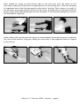
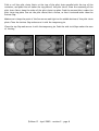
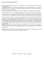
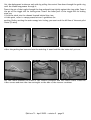
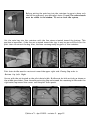
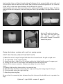
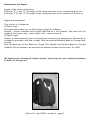
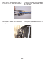
ADVANCE OUT
OWNER’S
GUIDE
BasiK Air Concept
559 chemin des Salles - 83300 Draguignan - France
tel: +33 (0)494 99 12 36 - [email protected]
Edition n°1 - April 2005 - revision 2
Table of contents
Overview
page 2
Parts List
page 3
AAD (Cypres and Vigil) Installation
page 4
Closing the reserve container
page 5-9
R.S.L. instructions
page 9
Closing the main container
page 10-13
Ripcords
page 14
3 rings Release
page 14
Before Jumping the Advance
page 15
Maintenance and Repairs
page 16
Advance
Size
SN#
Manufacturing
date
.................................................
.................................................
.................................................
.................................................
Edition n°1 - April 2005 - revision 2 - page 1
Introduction
BasiK Air Concept became the “second” French manufacturer with the Advance container system.
As the name suggests, Advance is a new generation of container system with many innovations.
The reserve container is characterized by the no-side-flaps technology and its partially exposed
reserve pilot chute. The no-side-flaps technology improves the extraction speed of the reserve
free bag and reduces the likelihood of container closing mistakes.
When you look at the Advance, what you see is the reserve free bag itself, reinforced with the
same material of which the container is built. Should you be dragged on the ground after a bad
landing, the free bag will offer the same resistance as regular flaps found on other container
brands.
The reserve free bag is protected on its lateral and top sides to avoid any snagging with the main
risers. The Advance container system is equipped with the 3-rings release system. Other standard features are discribed below. The harness is available in 2 types of webbing, type 7 or type
8 and you can even mix them.
The Advance system is equipped with a R.S.L. at no extra charge if needed.
Design and testing of the Advance were accomplished over a period of 15 months, and has
resulted in being one of the most innovating rigs on the market. We remind you that you have to
be certified to assemble and pack the Advance container system.
Advance comes with the following options included at no extra cost:
Hip rings
Velcro-free toggles
Front loop risers
Custom harness size
Custom colors*
Kill-line main pilot chute
Free-fly secured main opening pad
Z knife on ring cover
Leg strap junction
R.S.L system
* According to available list
The Advance container system has been tested in accordance with AS-8015B and EQ-530-03,
and is approved under TSO C-23d, JTSO-C23d and under French certifications QAC 121 and
EQ-530-03.
Edition n°1 - April 2005 - revision 2 - page 2
Parts List
The Advance container system is delivered with the following components:
Harness and container
Main risers with steering toggles
Main deployment bag with kill-line pilot chute or bunjie installed
Breakaway handle
Reserve handle
Reserve free bag and bridle*
Reserve Pilot chute**
Reserve steering toggles
Main closing loop
Reserve closing loop
One extra main closing loop
Rubber bands
Owner’s guide
All Advance harnesses are manufactured Cypres or Vigil-ready. FXC setup is an option. All
instructions to install these AAD can be found in the Student additional manual either.
No other brand component can be used with the Advance container system.
All components listed above can also be purchased individually from BasiK Air Concept and its
official dealers. Advance limitations of use are 110 kg at 150 kts.
BasiK Air Concept cannot be held responsible in case of an use over these weight and speed limits except for Student sizes 3 and 4 which are certified at the same airspeed but at a weight
limit of 130 kg.
* Only the Advance reserve free bag can be used with the Advance container system.
** Only the Advance reserve pilot chute can be used with the Advance container system.
Repack cycle must be done up to your own country regulations.
Edition n°1 - April 2005 - revision 2 - page 3
Install the AAD main unit into its pocket, cable connexion must be facing downward. Airtec
installation kit is only allowed for Cypres AAD type. Stow remaining cables and route the
cutter and the control unit into the white type 4 /1.5” channel toward the collar. For Advance
IN container type, please report to the Advance IN additional guide.
Close the protecting scratch flap. Set the cutter in its elastic band. Route the control unit
through the slit at collar level.
Slip the control unit into the back-pad and stowed it in its place. Close the protecting flap.
Installation is done. It is possible to install the control unit in the right ring cover (only available under request for student Cypres unit).
Edition n°1 - April 2005 - revision 2 - page 4
Reserve container closing instructions for the Advance OUT container system
This chapter deals with the procedures for packing a ram air reserve canopy into the Advance
OUT container system. Assembly and packing of the reserve must be accomplished by a
certified rigger, or by the manufacturer of the Advance container system. Before starting to
pack fill your rigger’s log book copy down the type of canopy, S/N and DOM from canopy data
panel.
Required tools:
One temporary pin (with warning flag attached)
One pull-up cord (120 cm minimumlengh)
One packing paddle or long bar
One T bar
Two 15 cm strips of 2,54 cm velcro loop
The closing loop must be between 8 cm to 8,5 cm long (report page for the appropriate length).
Make a thorough inspection of all components of the reserve parachute. Reserve pilot chute,
Reserve bridle, Free bag, Reserve canopy, Lines, Slider, Connector links, Harness and container
system.
Follow the canopy manufacturer’s directions for the inspection, attachment to risers, routing of
control lines, attachment of steering toggles, setting deployment brakes, and for flaking and
folding the reserve canopy. We highly recommends the Pro-pack for all ram-air reserves packed
into the Advance container system. This Pro-pack can be done in different maners. The purpose
of this guide is not to explain to you how to pack a reserve canopy but only how to set the freebag into the Advance container system. However, because of the new shape of the reserve container, it is important to fill both upper corners and the bottom of the free-bag as much as you
can. Avoid to have a lot of material in the sides of the free-bag. This filling must
be symmetrical to help you get a good secure hold of the two upper side closing devices.
Set the deployment brakes on each side by pulling the control line down through the guide ring
until the brake loop passes through it. Insert the stiffened upper portion of the toggle through
the loop and pull it up tightly against the ring guide. S-fold the slack between the toggle and the
brake-set, and stow it under the elastic located on top of the guide ring. Mate the scratch on
the toggle with the one located on the riser.
Edition n°1 - April 2005 - revision 2 - page 5
Place thebulk of canopy on each bottom side of the free bag. Lock the mouth of the
free-bag by making two stows with the suspension lines in the safety stow. Stow the remaining
of suspension lines in the line-stow pouch on the back of the bag. This is where it is useful to
use the velcro strips mentionned in the list of tools. Cover the hook velcro on the pouch with the
strips of loop velcro while stowing the lines into the pouch. S-fold the lines making sure to match
the full width of the pouch.
Leave a slack of 40 cm from the free bag to the risers. Remove the stripsof loop velcro and mate
the velcro atthe mouth of the pouch, making sure that none of the suspension lines are trapped
by the closure.
Edition n°1 - February 2005 - revision 1 - page 6
Prepare the reserve container. If the Cypres is installed, thread the reserve closing loop
through the Cypres cutter, and then the pull-up cord through the reserve closing loop. Lay the
reserve risers in the container so that the connector links are in the lower corners of the container.
Thread the pull-up cord and the reserve closing loop through the grommet of the free-bag. Lay
the bag in the container with the lines stow pouch facing down. Lay the lines protection flap
located over the AAD pouch on the free bag. Secure with the temporary pin. The bridle must
stay over the reserve container. S-fold 30 cm of bridle up and down on the free bag. Close the
two upper closing devices by setting them over the two corners of the free bag. Thread the
elastic through the grommet and secure it with 3 cm maximum of the free bag bridle after
makinga needle form to the bridle. Always keep the bridle toward the reserve container to avoid
any misrouting during the closing procedure. Make two folds up and down right over the closing
system. For the Advance container system equipped with the R.S.L. system report to page 8 .
“S” fold the remaining free-bag bridle up and down both sides of the temporary pin and pull-up
cord. Route the pull-up cord through the pilot chute and out through the cap. Be careful to not
route through in and out the springs.
Seat the lower end of the pilot chute on top of the free bag grommet and bridle, keeping the
pull-up cord tight. Compress the pilot chute and lock it with the temporary pin. Now pull all
fabrics out from under the top plate so that the pilot chute fabric is spread out. At this point,
check the lenght of the closing loop. If the pilot chute’s top plate can rock back and forth or
from side to side, the loop is too long. Shorten it so that when the pilot chute is compressed and
locked with the temporary pin, the top plate is firmly seated in the nest formed by the shape
of the free bag.
Edition n°1 - April 2005 - revision 2 - page 7
Fold or roll the pilot chute fabric at the top of the pilot chute parallel with the top of
container, and push this roll under the top plate of the pilot chute. Stow the remaining of
pilot chute fabric down the sides of the pilot chute top plate. Push the excess fabric under
pilot chute top plate. Fan out the pilot chute fabric excess, so that it extends wider than
bottom flap.
the
the
the
the
Make sure to keep the point of the fan narrow and tight to the middle bottom of the pilot chute
plate. Close the bottom flap and secure it with the temporary pin.
Close the top flap and secure it with the temporary pin. Push the side tuck flaps under the ears
of the bag.
Edition n°1 - April 2005 - revision 2 - page 8
1) Without R.S.L. Close the container with the reserve cable pin. Remove the temporary pin.
2) With R.S.L. Thread the reserve cable through the upper guide ring then through the R.S.L.
ring, then through the lower guide ring. Close the container with the reserve pin. Remove the
temporary pin.
This system doesn’t replace the normal activation of the reserve handle. As any mecanical
system, it might not work. Remember, you always need to make the full safety procedure,
cutaway the main and activate the reserve. For the few cases where immediate reserve
activation may not be desired, the Advance R.S.L. features a quick-release which can be used to
disconnect it. This quick release consists of a snap-shackle which is normaly attached to a small
ring on the inboard side of the left main riser. Release of the snap-shackle is accomplished by a
quick tug on the red ribbon attached to the release ring. Some jumpers feel that the R.S.L.
should not be connected during Canopy Relative Work, preferring to disconnect from the main
and then fall free of a “wrap“ before deploying the reserve. Also, if winds are high, the jumper
may disconnect the main canopy after landing to avoid being dragged. In this case the
quick-release can be used prior to landing to prevent an non desired activation of the reserve.
Assembling the R.S.L.
There are two rings mounted on the reserve top flap near the end of the ripcord housing. After
installing the reserve ripcord in the housing, the cable must be routed first, through the upper
guide ring, then through the R.S.L. ring, located at the end of the R.S.L. bridle and at last
through the lower guide ring. It is important to assemble the cable with the rings in this exact
order. Before the reserve container is closed, the R.S.L. bridle must be routed out from under
the reserve pin flap at the upper left. The velcro of the R.S.L. bridle should be mated to the
velcro on the left reserve riser to bring the bridle over the shoulder. Then the snap-shackle can
be connected to the small ring behind the inboard side of the left main riser. There should be
enough slack in the R.S.L. bridle so that the main riser can be pulled in any direction without
putting any tension on the reserve riser. Any slack in the R.S.L. bridle near the reserve flap must
be tucked under the reserve top flap. Caution although the R.S.L. is considered to be very
dependable, it is only a backup, and should never be relied upon entirely for activation of the
reserve. In the event of a breakaway or cutaway, the jumper should follow through by pulling
the reserve ripcord handle as if there was no R.S.L. It must also be understood that the R.S.L.
will not operate in the event of a total non opening of the main contaniner. Connect the R.S.L.
snap-shackle to the small ring behind the inboard side of the left main riser.Your R.S.L. system
is actived. To disactivate it, disconnect the snap-shackle.
Edition n°1 - April 2005 - revision 2 - page 9
Advance main setting instructions
This chapter details instructions of setting the main canopy into the main Advance
container system.
Assembly and packing of the main canopy must be done by a certified person or by the person
making the jump, in accordance with. These persons must follow the canopy manufacturer
instructions for these operations.
Basik Air Concept cannot be responsible in case of an assembly or packing or setting mistake.
1) Carefully inspect the main canopy, suspension lines, steering lines, slider and grommets,
connector links and other parts of the main canopy before assembling it with the risers. Replace
or repair any worn or damaged parts. Inspect the deployment bag, bridle, and pilot chute as well.
2) Attach the main canopy to the main risers, making sure that the canopy is facing the same
direction as the container system. Each suspension line must be clear all the way from its
attachment point through the slider grommet to the connector link without passing around any
other line. Make sure the steering lines are clear from the trailing edge of the canopy through
the slider grommets and through the ring guides on the rear risers to the steering toggles. Each
steering toggle must be securely tied to its control line at the location specified by the canopy
manufacturer.
Make sure as well that the connector links are tight enough so that they cannot be loosened with
the fingers alone. If soft links are used, please report to the canopy manufacturer to install and
secure them.
3)Attach the connector link of the main bridle (located inside the main bag) on the ring
located at the top of the main canopy and tighten it enough.
Edition n°1 - April 2005 - revision 2 - page 10
Set the deployment brakes on each side by pulling the control line down through the guide ring
until the brake loop passes through it.
Insert the pin of the toggle through the loop and pushit up tightly against the ring guide. Insert
the pin of the toggle into its locking stow. Insert the lower part of the toggle into its locking
stow too.
S-fold the slack into the channel located behind the riser.
At this point, refer to canopy manufacturer's guidelines for
packing. Before setting the main canopy into its bag, you must cock the kill line of the main pilot
chute (if used).
After the packing has been set into the main bag it must look like the below left picture.
Lay the risers between the sides of the reserve container and the risers covers. Close the
risers covers and stow the risers straight on the side of the reserve container.
Edition n°1 - April 2005 - revision 2 - page 11
Before setting the main bag into the container be sure to have cock
the kill line system of your main pilot chute (if used).The colored mark
must be visible in the window. If not re-cock the system.
Set the main bag into the container with the line stows oriented toward the bottom. This
position is important; if the line are oriented toward the top, it may be more difficult for the
pilot chute to extract the bag. Also, the lines can snag easily any part of the container.
Pilot chute bridle must be route out toward the upper right side. Closing flap order is:
-Bottom -Up -Left -Right
Secure with the pin located on the pilot chute bridle. Bridle must be laid verticaly as shown on
the middle above shot. Close the main protecting flap and stowed the remaining bridle under the
right main flap toward the corner and the pilot chute pouch.
Edition n°1 - April 2005 - revision 2 - page 12
Lay the pilot chute out flat with mesh side up. Fold some of the excess briddle on top of it, and
fold the pilot chute in half over the bridle. Now fold the curved side up about 10 cm. Fold the
bridle twice. Leave some space between the bridle and the ripcord.
Fold the pilot chute into thirds, and then roll it tightly until having cylindrical shape. Tuck the
slack of bridle into the pouch, then tuck the pilot chute. Spread widely the pilot chute into the
pouch.
Set the FF pad into its place.
The longer tuck tab goes into
the
pouch
over
the
pilot chute. Handle is oriented
toward the pouch.
Closing the Advance container with a pull-out opening system
FIRST COCK THE KILL LINE OF THE PILOT CHUTE
1) Mate the velcro from pull-out pad with the velcro located under the pull-out pad cover
at the right hand corner of bottom flap.
2) Stow the bridle in folds 15 to 20 cm long, and lay the folded bridle across the upper part
of the bag. Be sure not to tuck these folds down between the bag and the
bottom of the reserve container. Doing so may delay the action of pilot
chute.
3) Loosely fold the pilot chute and lay it across the bag.
4) Close the flaps as follow, bottom-top-left-right, securing the closing loop with the pin.
5) Tuck the slack under the right side flap.
7) Close the protecting flap.
Be sure that the connecting knot between the pilot chute and the briddle is not trap under the
flap.
Edition n°1 - April 2005 - revision 2 - page 13
Shots of hooktable and pillow breakaway handles.
Shot of reserve handle
THE 3-RINGS RELEASE SYSTEM
The periodic maintenance of the 3-rings release system is strongly recommended. This
maintenance has to be performed every month.
1) Extract the cable completely from its housing and disconnect the risers.
2) While the system is disassembled, closely inspect it for wear. Check the white locking loops
to make sure they are not frayed.
3) Check the velcro on the breakaway handle and main lift web to make sure it is clean and
adequately holds the handle.
4) Check the cable ends for a smooth finish. The ends are finished at the factory to have a
smooth, tapered surface. This prevents the cable from hanging up in the
loop. Check the cable ends and consult a rigger or manufacturer in case of a burr or hook is present.
5) Check the stiching, including that which holds the large rings to the harness.
6) Pull the housings downwards. They shouldn’t move downwards more than 1,30 cm.
7) Take each riser and vigorously twist and flex the webbing near where it passes through each
ring. The idea is to remove any set or deformation of the webbing. Do the same thing to the
white loop.
8) Check the housings for dents or other obstructions. Use the cable to do this.
9) Clean and lubricate the release cable with a light oil such as 3-in-1 brand. Put a few drops on
a paper towel and firmly wipe the cable a few times. A thin, invisible film should remain; too much
oil would attract grit and dirt, or the oil could become tacky in cold weather, thus requiring more
strength.
10) Inspect the fittings at the end of each housing. If one of these fittings were to come off
the housing, a riser might release prematurely.
11) If any wear is found, consult a rigger of the manufacturer before using the Advance.
12) Reassemble the system. Double check it. Make sure the risers are not reversed. Only the
risers provided by Basik Air Concept are allowed to be installed on the Advance harness/container system. It is formally forbidden to modify the risers or to use any other type of risers.
Edition n°1 - April 2005 - revision 2 - page 14
Assembly of the 3-rings system
1) Thread the cable into its housing and stick the handle to the harness. The handle should be
positioned as close to the ends of the housings as possible so that no cable is exposed.
2) With the rings of the riser facing toward the floor, pass the ring on the end of the riser
through the large harness ring from above. Fold it back toward the canopy and riser.
3) Thread the smallest ring through the middle ring in the same way, but make sure it does not
pass through the large ring.
4) Thread the white loop through the small ring only and then through the riser grommet so it
pokes out at the back of the riser.
5) Thread the white loop through the grommet on the end of the cable housing. The flat side of
the cable housing grommet should lay against the riser.
6) Thread the yellow cable through the white loop, making sure the loop is not twisted. Make
sure you do not bend the cable too sharply or kink it. Insert the free end in the channel on the
back of the riser.
7) Repeat the above steps with the other riser.
Before jumping the Advance container system
Before using the Advance container system, you must read this guide and proceed to the
following checks. These checks must be done at least once a month or after 50 jumps. The
maintenance (if needed) must be done by a qualified person (up to the country of use regulations).
Velcros, spandex pouch and reserve elastic bands closing system
Main and reserve closing loops
Harness, all webbings, chest strap and leg straps
Stiches of the container and harness
Routing of handles, cables and bridles
Housings and cables
Main pilot chute and bridle
3-rings system
Main risers
All hardwares
Grommets
Main deployment bag
R.S.L if installed on your rig
Edition n°1 - April 2005 - revision 2 - page 15
Maintenances and Repairs
Length of the reserve closing loop
From size “Z” to size “2”, the length of the closing loop must be set between 8 and 8.2 cm.
From size “3” to size “4”, the length of the closing loop must be set between 8.2 and 8,5 cm.
Rigging and maintenance
They are set in 2 categories:
1) Class 1 repair
Everything can be done by a certified rigger except the following:
Harness - reserve container and all parts identified as a “Part Number” and listed into the
capability list (reserve bag - reserve pilot chute - reserve ripcord).
2) Class 2 repair
All work on the harness and reserve container must be done by the manufacturer. No third party
is allowed to proceed to this kind of repair. Only raw material allowed by BasiK Air Concept must
be used.
Only the spare parts with a BasiK Air Concept “Part Number” and listed on BasiK Air Concept
capability list are allowed to be used with the Advance System since February 1st, 2000.
We thank you for choosing the Advance system, and we hope for your continued confidence
in BasiK Air Concept sarl.
Edition n°1 - April 2005 - revision 2 - page 16
ADDITIF AUX MANUELS
DES SAC-HARNAIS ADVANCE
FABRIQUES PAR BASIK AIR CONCEPT
(février 2006)
ADDITIVE TO ADVANCE
HARNESS-CONTAINER USER MANUALS
MANUFACTURED BY BASIK AIR CONCEPT
(february 2006)
Après de longues recherches et de nombreux
tests, nous avons développé un nouveau type
de terminaux de gaine de libération. De part
leur nouveau design nous avons décidé de
faire cette additif afin que vous puissiez les
monter correctement sur le système de
libération.
Vous trouverez dans les pages suivantes les
étapes de ce montage mais aussi une
démonstation de l’erreur à ne pas faire.
After long researchs and many testings, we
have developped a new type of cutaway
housing terminal end. Because of its new
design we have decided to make this additive
of the user manual to protect you against
misrouting. Its goal is to show you the right
way to install the breakaway release system
with this new terminal end.
You will find in the following pages, all
assembly stages but also a demonstation in
last page of the mistake to be avoid.
This new design will bring you all satisfaction
because of its simplicity of use and also
because it increases the security which
characterized this new system.
Ce nouveau design vous apportera que
satisfaction de part sa simplicité d’utilisation
mais aussi de part l’augmentation de sécurité
qui caractérise ce système.
Basik Air Concept 559 Chemin des Salles - 83300 Draguignan - France
Tel: 33(0) 4 94 99 12 36 - Fax: 33(0) 4 94 39 89 37 - E-mail: [email protected]
Comme vous le voyez le traditionnel oeillet a
été remplacé par une pièce cylindrique en inox
muni de plusieurs fenêtres. Les avantages de
ce système sont:
- Profil identique à la gaine libération
- Protection totale de la bouclette
- Plus de mise en travers du terminal
- Plus de possibilité de succion du cable
As you can see the old grommet has been
replaced by a cylindrical shape inox piece
equiped with several windows. Advantages of
this sytem are:
- Same shape as the breakaway housing
- Complete protection of the white loop
- No more side setup of the terminal end
- No more cable sucking possibility
Ce terminal a 4 fenêtres.
1 dans laquelle le cable passe, 2 petites
rondes, la boucle blanche passe dans l’une
d’elles et 1 long oval qui permet d’installer le
cable et de visionner le cheminement.
This terminal end has 4 windows.
1, in which the cable run through, 2 little
rounds in which the white loop goes in one of
them, and 1 long oval which allow to install the
cable and to check the routing.
page 2
Vue du cable passant dans la gaine et dans le
terminal de gaine.
View of the cable running into the housing and
the terminal end.
Passage de la boucle dans l’oeillet de
l’élévateur.
Routing of the white loop through the riser’s
grommet.
Passage de la boucle par une des petites fenêtres rondes.
Running of the white loop through one of the
little round window.
page 3
Insérer le cable dans la boucle et rangez le.
Le montage doit être comme sur cette photo.
Fit the cable through the white loop and stow
the remaining cable. Assembly must be done
like on this photo.
Vue finale de la gaine de libération installée
sur le système 3 anneaux.
Final setting of the breakaway housing on the
3 ring release system.
page 4
ATTENTION
WARNING
Erreur de montage.
Attention de ne pas faire passer la
boucle par la grande fenêtre ovale.
Dans ce cas la libération intempestive
est assurée. Vérifier bien que le
cheminement de la boucle passe
uniquement par l’une des 2 petites
fenêtres rondes.
Routing mistake.
Beware to not run the white loop by or
through the large oval window. If you
do so, a non intentionnal cutaway will
happened. Check carefully that the
white loop routing goes exclusively by
one of the little round windows.
Cette photo montre l’erreur de montage à
ne pas faire.
The above photo shows the routing mistake
to be avoided.
Basik Air Concept, vous souhaite de
bons sauts avec ce nouveau système.
Basik Air Concept, wish you good jumps
with this new system.
page 5