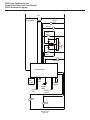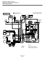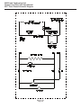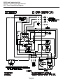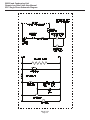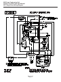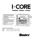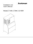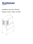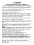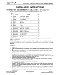
1
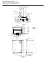
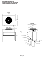
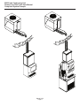
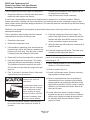
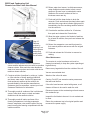
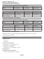
Installation and User Manual
for
Prodigy Eclipse Cuber
model EH222 C with ECC Condensing Unit
EH222 and Condensing Unit
Remote Low Side Cuber User Manual
Introduction:
This manual covers the assembly, installation, start
up, operation and maintenance of the 800 and 1000
remote low side cuber systems.
Contents
Configuration . . . . . . . . . . . . . . . . . . . . . . . . . . . . . . . . . . . . . . . . . . . . . . Page 3
Specifications and Location Information. . . . . . . . . . . . . . . . . . . . . . . . . . . . . . . . . Page 4
Cabinet Drawings, Ice Making Head . . . . . . . . . . . . . . . . . . . . . . . . . . . . . . . . . . Page 5
Cabinet Drawings, Condensing Unit. . . . . . . . . . . . . . . . . . . . . . . . . . . . . . . . . . Page 6
Pre-Installation Details. . . . . . . . . . . . . . . . . . . . . . . . . . . . . . . . . . . . . . . . . Page 7
Create the System. . . . . . . . . . . . . . . . . . . . . . . . . . . . . . . . . . . . . . . . . . . . Page 8
Completed System Example . . . . . . . . . . . . . . . . . . . . . . . . . . . . . . . . . . . . . . Page 9
Place Remote System. . . . . . . . . . . . . . . . . . . . . . . . . . . . . . . . . . . . . . . . . . Page 10
Tubing. . . . . . . . . . . . . . . . . . . . . . . . . . . . . . . . . . . . . . . . . . . . . . . . . . Page 11
Place Ice Making Head. . . . . . . . . . . . . . . . . . . . . . . . . . . . . . . . . . . . . . . . . Page 12
Drain Connections. . . . . . . . . . . . . . . . . . . . . . . . . . . . . . . . . . . . . . . . . . . . Page 13
Water Supply: . . . . . . . . . . . . . . . . . . . . . . . . . . . . . . . . . . . . . . . . . . . . . . Page 14
Electrical: . . . . . . . . . . . . . . . . . . . . . . . . . . . . . . . . . . . . . . . . . . . . . . . . Page 15
Connect Refrigeration. . . . . . . . . . . . . . . . . . . . . . . . . . . . . . . . . . . . . . . . . . Page 16
Complete the Installation . . . . . . . . . . . . . . . . . . . . . . . . . . . . . . . . . . . . . . . . Page 17
Reference for Start Up: Controller Operation . . . . . . . . . . . . . . . . . . . . . . . . . . . . . . Page 18
Initial Start Up . . . . . . . . . . . . . . . . . . . . . . . . . . . . . . . . . . . . . . . . . . . . . . Page 19
Ice Thickness and Water Purge Adjustment. . . . . . . . . . . . . . . . . . . . . . . . . . . . . . . Page 20
Adjustable Ice Level Control. . . . . . . . . . . . . . . . . . . . . . . . . . . . . . . . . . . . . . . Page 21
Cleaning, Sanitation and Maintenance . . . . . . . . . . . . . . . . . . . . . . . . . . . . . . . . . Page 22
Operational Characteristics 800 lb system . . . . . . . . . . . . . . . . . . . . . . . . . . . . . . . Page 24
Operational Characteristics 1000 lb system. . . . . . . . . . . . . . . . . . . . . . . . . . . . . . . Page 24
What to do before calling for service: . . . . . . . . . . . . . . . . . . . . . . . . . . . . . . . . . . Page 25
EH222 Schematic Diagram . . . . . . . . . . . . . . . . . . . . . . . . . . . . . . . . . . . . . . . Page 26
EH222 Wiring Diagram . . . . . . . . . . . . . . . . . . . . . . . . . . . . . . . . . . . . . . . . . Page 27
ECC Three Phase Schematic Diagram . . . . . . . . . . . . . . . . . . . . . . . . . . . . . . . . . Page 28
ECC Three Phase Wiring Diagram. . . . . . . . . . . . . . . . . . . . . . . . . . . . . . . . . . . Page 29
ECC Single Phase Schematic Diagram. . . . . . . . . . . . . . . . . . . . . . . . . . . . . . . . . Page 30
ECC Single Phase Wiring Diagram . . . . . . . . . . . . . . . . . . . . . . . . . . . . . . . . . . . Page 31
March 2013
Page 2
EH222 and Condensing Unit
Remote Low Side Cuber User Manual
Configuration
A remote low side cuber system includes two sub
systems: an ice making head and a remote air cooled
condensing unit. This manual covers the EH222 head
and the condensing units that go with it.
The ice making heads are designed for use indoors
in a controlled environment. The remote condensing
units are designed to operate outdoors. Each subsystem has limits for power, water and temperature.
Operational Limitations:
Minimum
Air Temp (at head) 50oF
Air Temp (CU)
-20oF.
Water Temp
40oF.
Water Pressure
20 psi
Water Conductivity 10 microSiemens/cm
Voltage (at head)
104
Voltage (CU)
198
CU= Condensing Unit
Maximum
100oF.
120oF.
100oF.
80 psi
any
126
253
Do Not operate the machine in conditions beyond
these limitations. Doing so will void the warranty.
800
800
1000
1000
Refer to the warranty coverage in effect when the
equipment was sold. Warranty statements are
included with each product.
Systems:
Ice making heads and condensing units have their
own model and serial numbers. They must be
combined to create a remote cuber low side system.
Notes: Voltage Codes are at the end of the model
number. Codes read Voltage/Hertz/Phase. Those
related to these products include:
-1 = 115/60/1
-3 = 208-230/60/3
-32 = 208-230/60/1
System Information
Tubing kits are required to connect the head to the
condensing unit.
Interconnecting 24 volt control wire ships with the
condensing unit.
Ice Making Head
System Size Condensing Unit (CU)
Model
ECC0800-32A
ECC0800-3A
ECC1410-32A
ECC1410-3A
Warranty
Electrical (volts/Hz/phase
208-230/60/1
208-230/60/3
208-230/60/1
208-230/60/3
Scotsman ice systems are designed and
manufactured with the highest regard for safety and
performance. They meet or exceed common agency
standards.
Scotsman assumes no liability of responsibility of
any kind for products manufactured by Scotsman
that have been altered in any way, including the use
of any part and/or other components not specifically
approved by Scotsman.
Scotsman reserves the right to make design changes
and/or improvements at any time. Specifications and
design are subject to change without notice.
March 2013
Page 3
Model
EH222SL-1C
same
same
same
Electrical (volts/Hz/phase)
115/60/1
same
same
same
EH222 and Condensing Unit
Remote Low Side Cuber User Manual
Specifications and Location Information
Model
Electrical
volts/Hz/phase
EH222SL-1C
ECC0800-32
ECC0800-3
ECC1410-32
115/60/1
208-230/60/1
208-230/60/3
208-230/60/1
Minimum
Circuit
Ampacity
1.13
14.8
10.6
14.5
Maximum
Fuse Size
System Charge,
oz of R-404A
Cabinet Size*
w” x d” x h”
Unit Weight
(lb)
15
20
15
30
shipped w/none
192
192
224
22 x 16.5 x 29
32 x 39 x 39.75
32 x 39 x 39.75
32 x 39 x 39.75
90
224
32 x 39 x 39.75
ECC1410-3
208-230/60/3
9.1
20
* See cabinet drawings for detailed dimensions.
Location Limitations
Condensing unit
Maximum Distance between Head and Condensing
Unit: Limited to the length of the longest available
single tubing kit, 75 feet.
The dataplate on the end contains the model number,
serial number, electrical data and system refrigerant
charge.
Maximum Condensing Unit Elevation over Ice Making
Head: 35 feet.
A second plate, located behind the side panel on the
deck, also lists the model number, serial number and
refrigerant charge.
Note: Elevations greater than 20 feet require
installation of a suction line trap at the 20 foot mark.
Maximum Ice Making Head Elevation over
Condensing Unit: 15 feet.
Line Routing:
•
•
•
•
llowed: One rise after a drop.
A
Allowed: One drop after a rise.
Not Allowed: More than one rise after a drop
Not Allowed: More than one drop after a rise.
Model Number Locations
Ice Making Head
The dataplate on the back of the ice machine contains
the model number, serial number and electrical data.
A second plate, located behind the front panel at
the lower right front, also lists the model and serial
numbers.
March 2013
Page 4
EH222 and Condensing Unit
Remote Low Side Cuber User Manual
Cabinet Drawings, Ice Making Head
131.70
5.19
115.95
4.57
79.38
3.13
68.20
2.69
42.80
1.69
3/8" LIQUID LINE
24
.95
ELECTRICAL CORD
ACCESS HOLE
INTERFACE CABLE
ACCESS HOLE
1/2" COOL VAPOR LINE
67.56
2.66
34.04
1.34
34.04
1.34
24.89
.98
POTABLE WATER INLET 3/8"
3/4" SUCTION LINE
DETAIL A
TOP VIEW
482.60
19.00
47.72
1.88
EH222
ICE HEAD
83.82
3.30
82.55
3.25
ICE DROP AREA
A
263.65
10.38
76.20
3.00
273.05
10.75
MINIMUM BIN
TOP OPENING
ULTRA SONIC
BIN LEVEL
SENSOR
82.55
3.25
212.85
8.38
152.40
6.00
LINE SET, POTABLE WATER INLET 3/8",
120V AC, AND INTERFACE CABLE
SEE DETAIL "A"
581.35
22.89
426.03
16.77
736.60
29.00
381
15.00
558.80
22.00
REAR VIEW
DRAIN 3/4" PVC FEMALE
REAR, LEFT AND RIGHT SIDE ACCESS
March 2013
Page 5
416.74
16.41
LEFT SIDE VIEW
EH222 and Condensing Unit
Remote Low Side Cuber User Manual
Cabinet Drawings, Condensing Unit
TOP VIEW
992.81
39.09
814.22
32.06
SIDE VIEW
LINE SET AND ELECTRICAL ATTACHMENT SIDE
FRONT VIEW
32.05
1.26
TYP.
330.86
13.03
750.06
29.53
887.73
34.95
.88" ELECTRICAL INLET
1009.65
39.75
3/4" SUCTION LINE
1/2" COOL VAPOR LINE
3/8" LIQUID LINE
83.67
3.29
63.50
2.50
74.12
2.92
INTERFACE HARNESS
ACCESS HOLE
163.02
6.42
248.87
9.80
March 2013
Page 6
491.69
19.36
EH222 and Condensing Unit
Remote Low Side Cuber User Manual
Pre-Installation Details
Water
Note: The ice making section cannot be stacked
vertically.
Accessories such as bin adapters and tubing kits are
required to complete the installation.
Dispenser Adapter Kits:
•
•
•
ornelius ABS: KBTABS ED150: KBT40
C
Scotsman ID150: KBT40
Scotsman ID200 or ID250: KBT41
There are two ways water can contain impurities:
in suspension or in solution. Suspended solids can
be filtered out of the water. In solution or dissolved
solids must be diluted or treated. Water filters are
recommended to remove the suspended solids.
Bin Adapter Kits:
•
•
530P or B530S: KBT32
B
B948S: KBT34
Some filters or filter systems have treatment
chemicals in them for treating the suspended solids.
Tubing Kits:
•
•
•
•
Pure water does not exist. All water supplies contain
some amounts of impurities, although potable water
is, by definition, fit for human consumption. Because
the contents of the water to an ice machine directly
impact its performance, consideration should be given
to improving the water’s quality.
0 foot: 3BRTE20-EH
2
35 foot: 3BRTE35-EH
50 foot: 3BRTE50-EH
75 foot: 3BRTE75-EH
Note: Line set may have quick connects. The
condensing section may have quick connects. See
refrigeration system detailed instructions connection
details.
This ice machine has an adjustment for the amount
of water rinsed or purged. Water use adjustments
are customer convenience adjustments; they are not
factory defects and are not covered by warranty.
Items required for installation:
•
•
•
•
Ice making head
Condensing unit (includes interconnecting control
system wire)
Tubing kit. 20’, 35', 50’ or 75’ triple line set (liquid,
vapor and suction)
Bin or dispenser adapter
Special Considerations
The ice making section’s footprint is 22” wide by 16.5”
deep. The refrigeration connections can be routed up
or to the back. The drain may be routed out the back
at any position left to right; it may also be routed to
either side.
March 2013
Page 7
EH222 and Condensing Unit
Remote Low Side Cuber User Manual
Create the System
Plan the installation. The system consists of three
parts: the ice making head, the condensing unit and
the interconnecting tubing. Of these, the biggest
variable is the interconnecting tubing.
Tubing: The tubing consists of three insulated and
sealed soft copper tubes. One tube, the liquid line,
is 3/8” OD. The vapor tube is ½” OD and the suction
tube is ¾” OD. A site inspection will determine what
length of tubing is required for the installation.
In 2013 Scotsman made a change to the Eclipse
tubing kits:
•
•
Elevation: Condensing unit limited to 35 feet above
the ice making section.
Condensing Unit: Electrical power must be supplied to
the condensing unit, it will be separate from the head.
Ice making section location and attachment: The
unique footprint of the EH222 requires adapter kits to
allow placement on dispensers and bins.
The remote tubing connections are at the top of the
machine, and connections should not be made until
the machine is nearly in its final installed position.
The 115/60 Hz ice making section is cord connected
and requires an outlet within 6 feet of the installation.
Prior Tubing Kits: They each contain a small
holding charge of R-404A and have quick
connects at the ends.
Current Tubing Kits: The do not contain any
refrigerant and do not have quick connects.
Either type can be used to connect the head and
condensing unit.
Interconnecting wires: An interconnecting wire
harness is included with the condensing unit. One end
plugs into the ice making section and the other into
the condensing unit. The system will NOT operate
without this harness.
Exposed tubing: Minimize the amount of tubing
Check condensing unit for quick connects. If none,
exposed outdoors.
recover refrigerant from tubing and cut the quick
connects off.
Lineset
Ice machine head and condensing Ice machine head has stubs, condensing
unit both have stubs
unit has quick connects.
Has Quick Connect Fittings Cut quick connects off both ends
Cut off quick connects at condensing unit
end only
Does NOT have Quick
Use as supplied
Use as is at head, obtain kit KTE6-EH,
Connect Fittings
use 3 of 6 fittings on condensing unit end.
Excess tubing must be shortened at the job site.
Installations with greater than 20 feet of vertical lift
between ice machine and the compressor require
a suction line trap. The suction line requires careful
handling and large radius bends to prevent kinking.
Roof mounting: Some installations will require the use
of a hoist to lift the components to the roof.
Pad mounting: The condensing unit may be located
below the ice making section, up to a limit of 15 feet.
Distance from unit: Limited to the length of the
available tubing.
March 2013
Page 8
EH222 and Condensing Unit
Remote Low Side Cuber User Manual
Completed System Example
March 2013
Page 9
EH222 and Condensing Unit
Remote Low Side Cuber User Manual
Place Remote System
Roof preparation
Roof Pipe Curb or Pitch Pocket:
Most installations of this system will place the
condensing unit on the roof of a building. The roof
must be physically able to accept the load of the
equipment and the roofing material must be prepared
to prevent water leaks.
To avoid potential kinking of the refrigeration tubing,
avoid small, tight radius types of covers on pitch
pockets.
Follow local codes for the placement and attachment
of the equipment.
In most cases a mechanical lift, boom truck or crane
will be required to hoist the condensing unit.
Location
Mount unit to roof rails or curbs and secure with lag
screws or similar field supplied fasteners.
The condensing unit requires unobstructed air flow
to operate efficiently. A four foot space between
each intake side and a wall or other cabinet is
recommended.
Do not place where it will pick up hot discharged air
from an air conditioner or other refrigeration system
condensing unit.
Suggestions:
Orient the assembled unit so that the unit’s mounts
are parallel to the pitch of the roof to allow water to
drain freely.
Do NOT place the unit directly onto roof rock.
Space must also be reserved for service on the
condensing unit.
Roof Piercing:
The roof (or wall) must have a passage large enough
for the three refrigeration tubes and the control wire
to pass through. The minimum recommended size is
4” ID. In most areas the power supply may also pass
through the same passage. If there isn’t a passage
one must be created. In most cases this must be done
by a licensed and bonded roofer in order to maintain
the roof’s integrity.
March 2013
Page 10
EH222 and Condensing Unit
Remote Low Side Cuber User Manual
Tubing
The line set must be routed between the condensing unit and the ice maker’s location. During the transition
from quick connects to braze connections, the ice maker, condensing unit and line set may or may not have
quick connects, use this chart as a guideline for the proper action based on what is available at the site.
Ice making head has
sweat connections
Condensing unit has sweat connections
Condensing unit has quick connects
If line set does not have quick connects,
route and use as is.
If line set has quick connects, recover
refrigerant from line set and cut one
end of quick connects off.
If line set has quick connects, recover
refrigerant from line set and cut all quick
connects off.
Ice making head has
quick connects
If line set has quick connects, recover
refrigerant from line set and cut one end
of quick connects off.
If line set does not have quick
connects, must use KTE6-EH stub kit
to add for condensing unit end.
C0800CP or C1410CP will have quick
connects and may be used with this
head by obtaining KTE6-EH.
If line set does not have quick connects, Use the quick connects to make the
must use KTE6-EH stub kit to add for ice connection.
machine end.
In all cases the line set will need to be shortened to fit.
Do NOT leave excess line set exposed outdoors,
especially on a roof.
Refrigerant Recovery and System Evacuation Notice
In the event the refrigerant must be recovered from this system and the system evacuated, recover and
evacuate from the three ball valve access valves with the ball valves open.
March 2013
Page 11
EH222 and Condensing Unit
Remote Low Side Cuber User Manual
Place Ice Making Head
Remove from carton.
Water and Drain
Place adapter kit onto bin or dispenser top. If adapter
does NOT have gasket tape install tape such as
Scotsman part number 19-0503-04. The adapter to
ice head base MUST be sealed with gasket tape or
food grade sealant.
The ice maker requires an adequate potable water
supply and a gravity drain.
Attachment
ABS (Automatic Beverage Dispenser) in drive up
installations: Route refrigerant tubing and install drain
and water supply tubing onto ice making section
before placing unit on the dispenser.
Place EH222 onto adapter, do not secure at this time.
Uncoil power cord and route to the power supply.
Plug interconnecting control wire to the wire harness
in the ice making head.
Located at the top panel:
•
•
•
•
Refrigeration connections.
Interconnecting control wire.
Access port for water supply.
Power cord.
Determine how the drain will be connected to the ice
making section.
•
•
If access is available behind the unit, route the
drain in from the back.
If the unit is to be flush mounted to the back of
the dispenser and tight against the wall, route the
drain out either the left or right.
In some tight situations it will be necessary to
assemble the ice making section to the dispenser or
bin and install the water and drain connections before
placing the system in its installed position. A loop of
water supply tubing will aid movement of the system.
In other tight situations the unit should have its water
and drain tubing connected and stubbed out before
placing on the dispenser or bin.
The drain fitting is adaptable to drain connections to
the left, right and back.
The drain may be routed to the left or right, allowing
the ice making section to be placed with its back tight
against a wall.
The unit is shipped ready to drain right. The drain
fitting elbow with PVC adapter can be rotated to drain
right, left or back.
Drain Fitting
EH222 Back View
March 2013
Page 12
EH222 and Condensing Unit
Remote Low Side Cuber User Manual
Drain Connections
Right Draining:
Left Draining: Rotate elbow to the other direction.
1. Connect ¾” PVC to the female PVC fitting.
If copper is required by code, remove the PVC
connector and install a ¾” FPT female copper fitting
onto the ¾” NPT male fitting. Do all soldering before
connecting to the male fitting.
Connect ¾” PVC to the PVC fitting.
2. In tight locations do the next step after the unit is
placed on the dispenser or bin.
3. Connect rigid drain tubing to the reservoir drain
tube. Route the drain either out the back, under the
unit (through the notch in the base) to the left side
or to the right side. A vent is built into the unit, so no
external vent is required.
Back Draining: Rotate elbow to face the back or
connect PVC directly into the ¾” FPT drain fitting.
No external drain vent is required, venting is internally
provided for.
Note: External drain tubing must be supported to
insure that it does not move and kink the internal
rubber tube.
Run the drain tubing to the building drain. Do not
“Tee” into any other drain, including the bin or
dispenser drain.
March 2013
Page 13
EH222 and Condensing Unit
Remote Low Side Cuber User Manual
Water Supply:
A 3/8" flare nut on tubing is located at the top panel,
near the refrigeration tubing.
Inside the hardware bag, inside the cabinet, a
3/8" inch double male flare adapter (flare union) is
supplied. Use the supplied adapter to make a 3/8"
male flare fitting for the water inlet.
Connect a cold, potable water supply to the 3/8” water
inlet fitting installed above. Use 3/8" OD copper or
other comparable sized tubing for the water supply.
Note: This is an NSF listed ice machine and contains
provisions for back-flow prevention in its design. No
external back flow preventer is required.
Communication Cable
Suction Line Insulation
Water Supply Connection
March 2013
Page 14
EH222 and Condensing Unit
Remote Low Side Cuber User Manual
Electrical:
Condensing Unit
Head
Route interconnecting control wire through proper
hole end of condensing unit and plug into the
connection on the control box.
Plug head’s power cord into a nearby 115 volt
electrical outlet.
Route power conduit (liquid tight) and wires to the
junction box of the ECC unit. Secure with the proper
type of connector.
Note: The power supply wires must be the correct
size and type per the National Electric Code.
Locate the nameplate on the ECC unit for the Voltage,
Phase, Minimum Circuit Ampacity and Maximum Fuse
Size. Either fuses or HACR type circuit breakers may
be used.
Follow all Local, State and National Codes.
Three Phase Notice: Check voltage between legs
at contactor. If there is a “wild leg” in the three phase
power supply move supply wires at the contactor so
the higher voltage is on L3, which connects to the
compressor motor only.
Electrical Junction Box
Dataplate Location
Communication Cable
Connect Cable Here
March 2013
Page 15
EH222 and Condensing Unit
Remote Low Side Cuber User Manual
Connect Refrigeration
At Head
Requires brazing, steps must be performed by an
EPA certified type II or higher technician.
1. With nitrogen flowing from condensing unit, braze
the liquid, vapor and suction line connections.
At Head:
1. Remove protective plugs from all three
connections and vent the nitrogen from the ice
machine.
2. Remove refrigeration hose from head. Be sure
valve cap is on tight.
3. Pull tubing bracket up and secure to back panel.
2. Route the each of the three tubes to its
connection.
At Condensing Unit
3. Remove the top panel and attach a refrigeration
hose with depressor to the 1/2” vapor line access
valve so the valve is OPEN. This is a vent for
nitrogen purging.
4. Remove screws holding tubing bracket to back
panel and lower it out of the way for brazing.
5. Clean tubing ends and position into stubs.
1. Remove nitrogen source.
2. Return valve cores to access valves.
3. Connect vacuum pump to all three access valves
(use two manifolds or two extra hoses and a tee)
and evacuate the tubing and head to at least a
300 micron level.
4. Remove vacuum pump and add R-404A vapor to
all three tubes to provide a positive pressure.
At Condensing Unit
1. Confirm connection
valves are fully
closed.
5. Leak check the braze connections and repair any
leaks.
2. Remove protective
plugs from all three
Valves Closed
connections.
Note: The full refrigerant charge is contained in the
receiver of the ice machine.
6. Open all three valves to full open.
3. Remove caps from access valve connections.
4. Remove cores from access valves.
5. Connect refrigeration hoses to access valves.
Liquid
6. Connect dry nitrogen source to liquid line
connection and vapor line connection.
Vapor
Suction
7. Shorten tubing to correct length, clean ends and
insert them into valve stubs.
Note: Be sure tube and stubs are round, dress with
swage tool if needed.
8. Add heat sink material to ball valve body.
9. Open nitrogen and flow 1 psi nitrogen into liquid
line and vapor line tubes and braze the liquid
line, vapor line and suction line tubes to the valve
stubs.
March 2013
Page 16
Refrigeration Connections
EH222 and Condensing Unit
Remote Low Side Cuber User Manual
Complete the Installation
After the utilities and refrigeration connections have
been made, secure the unit to the dispenser or bin
top.
Note: The refrigerant lines above the machine must
be able to move freely while the machine is being
moved into position.
Secure ice making section to dispenser or bin
adapter.
Final Check List Before Initial Start Up
1. Confirm that the ice making section is installed
indoors in a controlled environment.
Use strap/clips to secure unit:
•
hen used with Cornelius ABS adapter, install
W
clip on the side of the cabinet. Clip under edge of
adapter and secure to ice making section using
the screws provided in the hardware bag.
2. Confirm that all packing materials have been
removed from all products.
3. Confirm that the ice making section is level.
4. Confirm that all the refrigerant connections have
been made and checked for leaks.
5. Confirm that the proper power supply has been
turned on to the condensing unit.
Clip
6. Confirm that cold, potable water has been supplied
to the ice making section and checked for leaks.
7. Confirm that the water supply is adequate.
Note: If one side will be against a wall, do not use a
clip on that side. One clip is sufficient to secure the
unit.
•
or use on bin adapter, use clip (as a strap) on
F
back.
8. Confirm that there is adequate water pressure and
that any water filters have been checked to confirm
that the cartridges do not need changing.
9. Confirm that the proper size drain tubing has been
installed and properly routed.
10. Confirm that the ice making section has been
connected to the proper power supply.
11. Confirm that the interconnecting wire has been
routed and connected between the ice making section
and the condensing unit.
If the ice maker & bin or dispenser is not yet in its final
position gently move it there.
March 2013
Page 17
EH222 and Condensing Unit
Remote Low Side Cuber User Manual
Reference for Start Up: Controller Operation
The controller has four indicator lights, a code display,
four push buttons, and eleven component indicator
lights.
Component indicator lights
•
•
•
•
•
Indicator Lights
•
•
•
•
ower - on when there is power to the controller
P
Status - on in ice making mode
Water - on and blinking when there is no water
De-scale & Sanitize - on when it is time to clean
the machine
Code Display
•
Displays status and diagnostic codes
Push Buttons
•
•
•
•
On
Off
Manual Harvest
Clean
•
•
•
•
•
•
an - not used on this model
F
Water Pump - on when the pump is
Purge Valve - on when the purge valve is
Water Solenoid - on when the inlet water solenoid
valve is
Hot Gas - on when the vapor inlet valve and
harvest assist solenoid have power
Compressor - on when the compressor contactor
is energized
Ready to Harvest - on when the ice thickness
sensor has water touching it
Sump Empty - on when there is no water touching
the mid-length probe
Sump Full - on when water is touching the
shortest probe
SW2 - on when the curtain is open
SW1 - on when the curtain is open
Cycle Definitions:
Freeze: The refrigeration system is operating to
remove heat from the evaporators. The compressor,
fan motor, and water pump are on.
Harvest: The refrigeration system and water system
are operating to harvest the ice and rinse the
reservoir. The compressor is on for the full cycle, the
pump is on until the purge valve closes.
The inlet water valve opens and refills the reservoir.
The vapor and condenser by-pass valves are open
during the entire harvest cycle, as is the harvest assist
mechanism.
March 2013
Page 18
EH222 and Condensing Unit
Remote Low Side Cuber User Manual
Initial Start Up
Pre Start
A soak-out period of four hours is optional for this
system. If desired, powering the compressor unit
for four hours prior to start up allows the crankcase
heater to warm up the oil in the compressor.
Start Up
1. Connect power to the condensing unit and move
its toggle switch to Run or On.
2. Open the water supply valve.
3. Remove the head’s front panel. Check for any
packing or wires rubbing moving parts. Note
location of control board in upper left corner of the
machine’s front.
4. Remove any tape securing curtain to evaporator.
5. Switch on the electrical power to the EH222.
Observe that some of the control’s indicator lights
glow and its display shows O.
6. Push and release the ON button. The code display
will begin to blink F.
The purge valve opens, the water pump starts and the
inlet water valve opens to add water to the reservoir.
In a few seconds the purge valve closes and the
water pump stops. Water will flow into the machine
until the reservoir is full. The vapor valve and harvest
assist device will activate, then the compressor and
water pump will start. F will be on steady.
Note: Because the condensing unit is external to the
ice making section, no visible signs of operation will
be noticeable until the water begins to cool and frost
forms on the evaporator tubing.
7. Go to the condensing unit and confirm that the
compressor and fan motor are operating. Warm
air will be discharged from the condenser.
During the Freeze cycle move the curtain and observe
that either the SW1 or SW2 light on the control
board blinks On when the curtain moves away from
the evaporator and Off when returned to its normal
position.
Note: Moving the curtain during the Freeze cycle has
no affect on control function, but will cause water to
flow into the cube chute.
When enough ice has frozen, the Ready for Harvest
indicator light will be on steady. After it’s been on
steady for a few seconds Harvest will begin.
The display shows an H. The vapor valve in the
EH222 opens, and the harvest assist mechanism
activates. In the CU the condenser bypass valve
opens and the receiver inlet valve closes. In the
EH222, the purge valve opens to drain some water,
when it does the inlet water valve opens to refill the
reservoir. After a few seconds the purge valve closes
but the inlet water valve continues to fill the reservoir.
Harvest continues until the ice is released as a unit
and forces the curtain to open.
When the curtain opens it signals the controller that
harvest is complete, and it returns the unit to a freeze
cycle.
8. Check the ice harvested for proper bridge
thickness. The ice bridge is factory set at 1/8 inch.
If needed, adjust bridge thickness. Do NOT make
it too thin.
9. Return the front panel to its normal position and
secure it to the machine.
10.Instruct the user in the operation of the machine
and its maintenance requirements.
11.Fill out and mail the warranty registration form or
register it on line at www.scotsman-ice.com.
Observe the Ready for Harvest indicator light. It may
blink early in the cycle, that is normal. The control will
ignore that signal for the first 6 minutes of freeze.
March 2013
Page 19
EH222 and Condensing Unit
Remote Low Side Cuber User Manual
Ice Thickness and Water Purge Adjustment
Bridge Thickness - For the Service Tech Only
1/8 to 3/16”
Bridge
1. Push and hold Off till the machine stops.
2. Remove evaporator cover.
3. Remove curtain.
4. Use a hex wrench and rotate the bridge thickness
adjustment screw in 1/16 turn increments CW to
increase bridge thickness.
5. Rotate CCW to decrease bridge thickness.
Caution: Do not make the bridge too thin or the
machine will not harvest properly. Bridge thickness
adjustments are not covered by warranty.
6. Return curtain and evaporator cover to their
normal positions.
ice Bridge Thickness
7. Push and release the On button. Check next
harvest of ice. Repeat steps 1-6 if needed.
Water Purge Setting
The water purge is factory set to the automatic
position, suitable for most water conditions. The
setting can be changed to one of 5 manual settings or
left on automatic.
Setting
1
2
3
4
5
A
Water Type
Minimum - RO water or equivalent
Moderate - Low TDS, non RO
Standard - Use with typical water
Heavy - High TDS
Maximum - Very high TDS
Automatic - Factory setting
Adjustment
Screw
Bridge Thickness Adjustment Mechanism
To set:
1. Switch the machine OFF by holding the Off button
in until a number or the letter A shows on the
display.
2. Press and release the On button repeatedly until
the number on the display corresponds to the
desired setting.
3. Press and release the Off switch again to return to
the normal control state.
March 2013
Page 20
EH222 and Condensing Unit
Remote Low Side Cuber User Manual
Adjustable Ice Level Control
There is an adjustment post and an additional
indicator light to the right of the four indicator lights.
The ultrasonic ice level control allows the user to
control the point that the ice machine will stop making
ice before the bin or dispenser is full. Reasons for this
include:
•
•
•
easonal changes in ice used S
Planning to sanitize the bin
Certain dispenser applications where maximum
ice level is not desired
Use of control
There are several positions the ice level can be set
to, including Off (knob and label indicators lined up),
where it fills the bin until the standard bin control shuts
the machine off.
Ice
The cuber drops ice in large sections. That ice will
break up into random parts as it falls into the bin, but
some large sections may remain on top of the ice
in the bin. In a dispenser this ice will break up into
mostly individual cubes as the dispense mechanism
moves the ice.
Noise
The ice machine will make little noise when it is in
ice making mode. The compressor and fan motor are
remote from the ice making head. The water pump
in the ice making head will produce some sound. It
is also normal to hear some cracking just before the
harvest cycle begins. In addition, during the harvest
cycle the harvest assist solenoid will click twice as it
pushes the ice out and returns to its normal position.
The ice harvests as a unit or slab, which makes some
noise when it impacts the bin or dispenser. These
noises are all normal for this machine.
Rotate the adjustment post to the desired ice level.
The machine will fill up to that level and when it shuts
off the indicator light next to the adjustment post will
be On.
Suggested Adjustment Knob Position for use with the
ABS or Freestyle: first CW position - as shown above.
DO NOT ADJUST TOO LOW OR THE MACHINE
WILL STOP MAKING ICE
Note: Ice will build up in the bin or dispenser at an
angle, the distance set will be from the sensor to the
top of the ice. The sensor position is shown in the
cabinet layout diagrams.
The actual distance between the highest point of the
ice may be closer or further away than the distance
set, depending upon the angle of the ice.
March 2013
Page 21
EH222 and Condensing Unit
Remote Low Side Cuber User Manual
Cleaning, Sanitation and Maintenance
This ice system requires three types of maintenance:
•
Remove the build up of mineral scale from the ice
machine’s water system and sensors.
•
•
Sanitize the ice machine’s water system and the
ice storage bin or dispenser.
Clean the remote air cooled condenser.
It is the User’s responsibility to keep the ice machine and ice storage bin in a sanitary condition. Without
human intervention, sanitation will not be maintained. Ice machines also require occasional cleaning of their
water systems with a specifically designed chemical. This chemical dissolves mineral build up that forms during
the ice making process.
Sanitize the ice storage bin as frequently as local health codes require, and every time the ice machine is
cleaned and sanitized.
The ice machine’s water system should be cleaned
and sanitized a minimum of twice per year.
1. Remove the front panel.
2. Remove the evaporator cover.
3. If the machine is operating, push and release the
Harvest button. When the machine completes the
Harvest cycle it will stop. If the bin is full (b shows
in display) push and release the Off button.
4. Remove all ice from the storage bin or dispenser.
5. Push and release the Clean button. The yellow
Clean light will blink and the display will show C.
The machine will drain the reservoir and refill it.
Go onto the next step when the purge valve light
goes out.
6. Pour 12 ounces of Scotsman Clear 1 nickel safe
scale remover into the reservoir.
Ice machine scale remover
contains acids. Acids can
cause burns.
If concentrated cleaner comes
in contact with skin, flush with
water. If swallowed, do NOT
induce vomiting. Give large
amounts of water or milk. Call
Physician immediately. Keep
out of the reach of children.
7. Allow the ice machine cleaner / scale remover
to circulate in the water system for at least 10
minutes.
8. Push and release the Clean button again. The
yellow Clean light will be on continuously and the
machine will drain and refill the reservoir to flush
out the ice machine cleaner and residue.
9. Allow the drain and refill process to continue for at
least 20 minutes.
10.Push and release the Off button. The clean cycle
will stop and the display will show O.
Note: If unit has not been de-scaled for an extended
period of time and significant mineral scale remains,
repeat steps 5 - 10.
11.Mix a cleaning solution of 1 oz of ice machine
cleaner to 12 ounces of water.
12.Remove curtain from unit.
13.Locate ice thickness sensor. Squeeze mounting
legs together to release sensor.
14.Remove water distributor from ice machine by
disconnecting its hose, squeezing the retaining
snaps together and pushing the distributor to the
right as far as possible. Lift up to remove. Inspect
distributor for restricted orifice holes. Be sure all
holes are full open.
15.Locate water level sensor. Squeeze catches
together and pull up to remove sensor. Separate
probes from housing and wash all surfaces with
ice machine scale remover solution. Return
probes to holder.
March 2013
Page 22
EH222 and Condensing Unit
Remote Low Side Cuber User Manual
20.Return water level sensor, ice thickness sensor,
water distributors and curtains to their normal
positions. Be sure hose is reattached to water
distributor. Be sure all surfaces of the ice
thickness sensor are dry.
21.Push and hold the clean button to drain the
reservoir. Push and release the clean button again
and when the purge valve indicator light goes out,
immediately pour the remaining sanitizer solution
into the reservoir.
22.Circulate the sanitizer solution for 10 minutes,
then push and release the Clean button.
Inspect Orifice Holes
Step 15.
Release
probes by
pushing in on
white buttons
and pulling
probe down
out of holder.
16.Wash the metal surfaces of the ice thickness
sensor and the adjustment screw with ice machine
cleaner solution. Also wash the water distributor,
water level sensor probes and curtain with the ice
machine cleaner solution.
17.Create a solution of sanitizer by mixing a 1 gallon
or 4 liter solution of locally approved sanitizer
and clean, warm water. Use an EPA approved
food equipment sanitizer at the solution mix
recommended by the sanitizer manufacturer.
Scotsman also has a sanitizer, contact your local
Scotsman Distributor for information.
18.Thoroughly wash all surfaces of the ice thickness
sensor, water level sensor, curtain and water
distributor with the sanitizer solution.
19.Thoroughly wash all interior surfaces of the
freezing compartment, including evaporator
frames, evaporator cover and the part of the top
panel covering the freezing compartment with the
sanitizer solution.
23.Allow the water system to be flushed of sanitizer
for at least 20 minutes, then push and release the
Off button.
24.Return the evaporator cover and front panel to
their normal position and secure with the original
fasteners.
25.Push and release the On button to resume ice
making.
Other Maintenance
The remote air cooled condenser coil must be
cleaned occasionally to keep the system operating at
high efficiency.
Remove any large debris from the outside of the coil.
Vacuum accumulated dust.
Wash out the coils with water.
Caution: Do NOT use excessive water pressure as
that will bend the fins.
If the coils have become coated with grease, a coil
cleaner will have to be used to wash the coils.
Disconnect power to the condensing unit and remove
the condenser top.
Inspect the fan blade to be sure it is not cracked and
is clean.
Return the condenser top to its original position and
reconnect the power supply.
March 2013
Page 23
EH222 and Condensing Unit
Remote Low Side Cuber User Manual
Operational Characteristics 800 lb system
Cycle Times @ Condenser Temp/Cabinet Temp/Water Temp in degrees F.
70/70/50
90/90/70
Freeze
10 to 12 minutes
13 to 15 minutes
Harvest
1 to 1.5 minutes
1 to 1.5 minutes
System Pressures @ Condenser Temp/Cabinet Temp/Water Temp in degrees F
Suction at head, end of Freeze
Suction at head, Harvest - Peak
Discharge at Condensing Unit:
Freeze - 5 minutes in
70/70/50
26 to 31 PSIG
85 to 105 PSIG
230 to 250 PSIG
90/90/70
26 to 31 PSIG
105 to 125 PSIG
250 to 270 PSIG
120/110/100
19 to 21 minutes
.5 to 1 minute
120/110/100
30 to 35 PSIG
140 t0 160 PSIG
330 to 350 PSIG
Operational Characteristics 1000 lb system
Cycle Times @ Condenser Temp/Cabinet Temp/Water Temp in degrees F.
70/70/50
90/90/70
Freeze
8 to 9 minutes
10 to 11 minutes
Harvest
1 to 1.5 minutes
1 to 1.5 minutes
System Pressures @ Condenser Temp/Cabinet Temp/Water Temp in degrees F
Suction at head, end of Freeze
Suction at head, Harvest - Peak
Discharge at Condensing Unit:
Freeze - 5 minutes in
70/70/50
26 to 31 PSIG
85 to 105 PSIG
230 to 250 PSIG
90/90/70
27 to 32 PSIG
90 to 110 PSIG
240 to 250 PSIG
120/110/100
16 to 18 minutes
.5 to 1 minute
120/110/100
30 to 35 PSIG
140 to 160 PSIG
345 to 380 PSIG
Below information applies to both size systems:
Headmaster maintains a minimum discharge pressure during freeze of 217 PSIG + 25, -15 PSIG.
CPR Valve Setting: 55 - 60 PSIG.
Note: CPR allows a maximum low side pressure at the compressor. Maximum only occurs during harvest.
Refrigerant Charge
•
•
800: 192 oz.
1000: 224 oz
Compressor Amps, 800 model
•
Single Phase - 6 to 8 Three Phase - 5 to 7
Compressor Amps, 1000 model
•
Single Phase - 8 to 9, Three Phase - 6.3 to 5.2
Batch Weight: 8 lb
Discharge Pressure Cut Out Switch
•
Cuts Out at: 450 PSIG Resets at: 350 PSIG
March 2013
Page 24
EH222 and Condensing Unit
Remote Low Side Cuber User Manual
What to do before calling for service:
Reasons the machine might shut itself off:
•
•
•
•
•
Lack of water.
Freeze cycle takes too long.
Harvest cycle takes too long.
High discharge pressure.
Ice level control set wrong
Check the following:
1. Has the water supply to the ice machine or building been shut off? If yes, the ice machine will automatically
restart within 25 minutes after water begins to flow to it.
2. Has power been shut off to the ice machine? If yes, the ice machine will automatically restart when power
is restored.
3. Is the curtain open because some ice is stuck under it? If so, remove the ice and the machine should start
in a few minutes.
4. Check the adjustment knob of the ice level control. See page 21.
Note: Curtain can be removed & replaced anytime the machine is in a standby mode or when it is in a freeze
cycle. However, removal of the curtain during freeze will result in water flowing into the bin. Removal of the
curtain during harvest terminates harvest at that point and, if left off, will result in the machine shutting off.
To Manually Reset the machine.
1. Push and release the Off button.
2. Push and release the On button.
To Shut the Machine Off:
1. Push and hold the Off button for 3 seconds or until the machine stops.
March 2013
Page 25
EH222 and Condensing Unit
Remote Low Side Cuber User Manual
EH222 Schematic Diagram
L2
L1
LINE
HARVEST
ASSIST
SOLENOID
TRANSFORMER
12V
HOT GAS
VALVE
TO COMPRESSOR
SECTION
HGV
RELAY
CONTACTOR
RELAY
WATER VALVE
ELECTRONIC CONTROL
WATER
LEVEL
SENSOR
DISCHARGE
TEMP.
SUMP
TEMP.
ICE
THICKNESS
PROBE
CURTAIN
SWITCH 1
DUMP
VALVE
WATER
PUMP
March 2013
Page 26
CURTAIN
SWITCH 2
EH222 and Condensing Unit
Remote Low Side Cuber User Manual
EH222 Wiring Diagram
USE COPPER CONDUCTORS ONLY
1 DASHED LINES INDICATE FIELD WIRING WHICH MUST BE
INSTALLED IN ACCORDANCE WITH THE NATIONAL ELECTRICAL
CODE AND ALL STATE AND LOCAL CODES.
17-3111-01
BN/W
WATER
SOLENOID
DUMP
VALVE
HARV ASSIST
HOT GAS
MOT
PUMP
BN/W
W
SOLENOID
SOLENOID
TO COMPRESSOR
SECTION
W
W
R/W
SEE NAMEPLATE FOR PROPER
VOLTAGE REQUIREMENTS
AND MAXIMUM FUSE SIZE
INLET
POWER
CORD
BU
W
R
V
8
4
W
BN/W
WATER
LEVEL
SENSOR
R
BK
BK
V
HGV
RELAY
14 13
12 9
BN
L1
14 13
12 9
W
J9
1 2 3 4
Y
LINE
ELECTRONIC
CONTROL
J8
1 2
CURTAIN
SWITCH 2
TRANSFORMER
BK
GN/Y
J2
J6
1 2
CURTAIN
SWITCH 1
1 2 3 4 5 6 7 8
W
1 2 3 4
J7
THIS UNIT MUST
BE GROUNDED.
March 2013
Page 27
GN/Y
LOAD
O
J1
DISCHARGE
TEMP.
SENSOR
N
BK
1 2 3
V
SUMP TEMP.
SENSOR
TERM.
BLOCK
W
Y
J10
W
Y
COMP.
RELAY
W
ICE
THICKNESS
PROBE
BK
8 5
4 1
5
1
EARTH
ROUND
CAUTION:
MORE THAN ONE DISCONNECT MEANS MAY BE
REQUIRED TO DISCONNECT ALL POWER TO THIS UNIT.
EH222 and Condensing Unit
Remote Low Side Cuber User Manual
ECC Three Phase Schematic Diagram
March 2013
Page 28
EH222 and Condensing Unit
Remote Low Side Cuber User Manual
ECC Three Phase Wiring Diagram
March 2013
Page 29
EH222 and Condensing Unit
Remote Low Side Cuber User Manual
ECC Single Phase Schematic Diagram
March 2013
Page 30
EH222 and Condensing Unit
Remote Low Side Cuber User Manual
ECC Single Phase Wiring Diagram
March 2013
Page 31
SCOTSMAN ICE SYSTEMS
775 Corporate Woods Parkway
Vernon Hills, IL 60061
www.scotsman-ice.com
800-726-8762
17-3458-01