1
GE Fanuc Automation
CIMPLICITY® Monitoring and Control Products
CIMPLICITY HMI Plant Edition
CimEdit
Operation Manual
GFK-1396F
July 2001
GFL-005
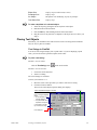
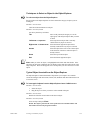
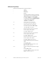
Following is a list of documentation icons:
Warning notices are used in this publication to emphasize that hazardous voltages, currents,
temperatures, or other conditions that could cause personal injury exist in the equipment or
may be associated with its use.
In situations where inattention could cause either personal injury or damage to equipment, a
Warning notice is used.
Caution provides information when careful attention must be taken in order to avoid
damaging results.
Important flags important information.
To do calls attention to a procedure.
Note calls attention to information that is especially significant to understanding and
operating the equipment.
Tip provides a suggestion.
Guide provides additional directions for selected topics.
This document is based on information available at the time of publication. While efforts have been made to be accurate,
the information contained herein does not purport to cover all details or variations in hardware or software, nor to
provide for every possible contingency in connection with installation, operation, or maintenance. Features may be
described herein which are not present in all hardware and software systems. GE Fanuc Automation assumes no
obligation of notice to holders of this document with respect to changes subsequently made.
GE Fanuc Automation makes no representation of warranty, expressed, implied, or statutory with respect to, and
assumes no responsibility for the accuracy, completeness, sufficiency, or usefulness of the information contained herein.
No warranties of merchantability or fitness for purpose shall apply.
CIMPLICITY is a registered trademark of GE Fanuc Automation North America, Inc.
Windows NT and Windows 95 are registered trademarks of Microsoft Corporation
This manual was produced using Doc-To-Help®, by WexTech Systems, Inc.
Copyright 2000-2001 GE Fanuc Automation North America, Inc.
ii
CIMPLICITY HMI CimEdit Operation Manual–July 2001
GFK-1396F
Preface
Contents of this Manual
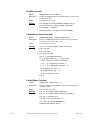
Chapter 1. Introduction: Introduces you to CIMPLICITY MMI and MES/SCADA
for Windows 95 and Windows NT and CimEdit.
Chapter 2. Opening CimEdit: Provides procedures for opening CimEdit through
the CIMPLICITY HMI Configuration Cabinet.
Chapter 3. Configuration Overview: Gives an overview of the CimEdit
configurtion process.
Chapter 4. Configuring a CimEdit Screen: Describes how to use the CimEdit
screen to its fullest potential.
Chapter 5. Creating a Preliminary Layout: Describes how to find, create and
place several objects that you can configure for your CimEdit screen.
Chapter 6: Saving Time with Linked Objects: Shows you how to create and use
Linked Objects.
Chapter 7. Creating Expressions: Dexcribes the several functions and operators
available in the Expression editor that can be used throughout CimEdit.
Chapter 8. Applying Inanimate Visual Features: Explains how to change objects’
features, such as size, shape and color.
Chapter 9. Using Points for Values: Describes how to incorporate points into your
CimEdit configuration.
Chapter 10. Using Variables: Describes variables and when using them is a viable
alternative to using points.
Chapter 11. Configuring Runtime Movement and Animation: Explains how to
make runtime objects move, rotate, change size, fill up and change color to reflect
changes specified conditions.
Chapter 12. Creating Events in CimEdit: Explains an event’s role in the CimEdit
confuration and lists available events.
Chapter 13. Creating Procedures in CimEdit: Explains a procedure’s role in the
CimEdit configuration and lists the several actions that can be included in a
procedure.
GFK-1396F
iii
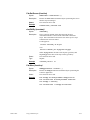
Chapter 14. Using CimEdit Scripts: Explains a script’s role in the CimEdit
confuration and how a system administrator can incorporate scripts into the CimEdit
configuration.
Chapter 15. Taking Advantage of ActiveX Controls: Describes how to
incorporate ActiveX controls in your CimEdit screen.
Chapter 16. Point Addressing: Defines point addressing and, when and how to use
it
Chapter 17. Monitoring Point Attributes: Provides the Attribute_Point syntax to
let a user monitor the attributes of configured points through CimView.
Appendix A. CimEdit Text File Syntax: Documents the syntax for a text file
created with the /converttoctx command line option.
Appendix B. Managing CimEdit Screens: Discusses screen performance issues,
installing a screen, and command line options for installed screens and interactive
functions.
Appendix C. CimEdit Global Parameters: Documents the global parameters
available to tune CimEdit and CimView.
iv
CIMPLICITY HMI CimEdit Operation Manual–July 2001
GFK-1396F
Related Publications
For more information, refer to these publications:
CIMPLICITY HMI Plant Edition User's Manual (GFK-1180)
CIMPLICITY HMI Plant Edition Device Communications Manual (GFK-1181)
CIMPLICITY HMI Trending Operation Manual (GFK-1260)
CIMPLICITY HMI SPC Operation Manual (GFK-1413)
CIMPLICITY HMI Recipes Operation Manual (GFK-1303)
CIMPLICITY HMI Plant Edition Basic Control Engine Language Reference
Manual (GFK-1283)
CIMPLICITY HMI Plant Edition Basic Control Engine Program Editor
Operation Manual (GFK-1305)
CIMPLICITY HMI Plant Edition Basic Control Editor Event Editor and BCEUI
Operation Manual (GFK-1282)
GFK-1396F
v
Contents
Introducing CimEdit
1-1
Welcome to CimEdit.............................................................................................................. 1-1
CimEdit Tools ........................................................................................................................ 1-2
CimEdit Features.................................................................................................................... 1-3
A Word about CimView ........................................................................................................ 1-5
Opening CimEdit
2-1
About Opening CimEdit from the Workbench ...................................................................... 2-1
Opening a New CimEdit Screen .............................................................................. 2-1
Opening an Existing CimEdit Screen ...................................................................... 2-3
Reviewing CimEdit Configuration
3-1
CimEdit Configuration Overview .......................................................................................... 3-1
Looking over the CimEdit Window......................................................................... 3-1
Reviewing Configuration Steps ............................................................................... 3-2
Information Requirements for CimView................................................................................ 3-3
Choosing Data Sources ............................................................................................ 3-3
Determining User Interaction with CimView Screens............................................. 3-5
Determining where Runtime Information will be used............................................ 3-5
CimEdit Configuration Choices ............................................................................................. 3-6
Estimating the Number of Screens for a Project...................................................... 3-6
Selecting Objects to Convey CimView Data ........................................................... 3-6
Unleashing the Power of CimView.......................................................................... 3-7
Adding ActiveX and Other Objects ......................................................................... 3-9
Dialog Boxes Overview ....................................................................................................... 3-10
CimEdit Screen Configuration Example .............................................................................. 3-11
Configuring a CimEdit Screen
4-1
About CimEdit Screens.......................................................................................................... 4-1
Accessing the Screen Properties .............................................................................. 4-2
Screen Appearance................................................................................................................. 4-3
Specifying the Screen’s Size.................................................................................... 4-3
Specifying the Screen’s Color ................................................................................. 4-4
Workspace Aids Displayed on the Screen.............................................................................. 4-5
Displaying a Grid on your CimEdit Screen ............................................................. 4-5
Displaying the Mouse Location ............................................................................... 4-6
Choosing What Toolbars to Display........................................................................ 4-7
Zooming the CimEdit Screen Display Size ............................................................. 4-8
Specifying the Undo Stack Size for a CimEdit Screen .......................................... 4-10
Variables at the Screen Level............................................................................................... 4-11
Events and Procedures at the Screen Level.......................................................................... 4-13
Creating Events with Procedures at the Screen Level............................................ 4-13
Dealing with Procedures Independent of Events ................................................... 4-16
GFK-1396F
Contents-vii
Screen Scripts....................................................................................................................... 4-18
Ambient Properties .............................................................................................................. 4-19
Help for a CimEdit Screen or Object ................................................................................... 4-20
Designating a Help File for a Screen or Object ..................................................... 4-20
Creating Popup Menu Items for the Screen or Objects.......................................... 4-22
CimEdit Screen or Object Name .......................................................................................... 4-23
CimEdit/CimView File Types and Search Paths.................................................................. 4-24
Deciding the Format for a CimEdit Screen............................................................ 4-24
Understanding the CimEdit/CimView Screen Search Sequence ........................... 4-29
Creating a Preliminary Layout
5-1
About Creating a Preliminary Layout .................................................................................... 5-1
Available Objects ................................................................................................................... 5-2
Creating Basic Graphic Objects............................................................................... 5-2
Placing Text Objects................................................................................................ 5-9
Placing Objects from the Object Explorer ............................................................. 5-12
Using a Class Object Graphic ................................................................................ 5-19
Inserting ActiveX and OLE controls ..................................................................... 5-23
Special Pasting Objects onto a CimEdit Screen..................................................... 5-30
Object Layout....................................................................................................................... 5-31
Configuring Sets of Objects in CimEdit ................................................................ 5-31
Configuring Groups of Objects in CimEdit ........................................................... 5-33
Moving Objects on a CimEdit Screen.................................................................... 5-40
Changing Objects Tab Order ................................................................................. 5-49
Saving Time with Linked Objects
6-1
About Linked Objects ............................................................................................................ 6-1
Basic Principles about Linking Objects ................................................................................. 6-2
Choosing to Copy or Link an Object ....................................................................... 6-2
Choosing Public or Private Variables ...................................................................... 6-5
Linked Object Creation .......................................................................................................... 6-6
Creating Linked Objects .......................................................................................... 6-6
Updating Linked Objects ......................................................................................... 6-8
Linked Object Placement ....................................................................................................... 6-9
Creating Copies or Links ......................................................................................... 6-9
Finding the Source of Linked Objects ................................................................... 6-10
Assigning Public Variable ID Assignments to Links............................................. 6-11
Protected Linked Objects ..................................................................................................... 6-13
Creating a Protected Link Example ....................................................................... 6-13
Creating Expressions
7-1
About the Expression Editor .................................................................................................. 7-1
Alarm Functions ...................................................................................................... 7-3
Arithmetic Operations.............................................................................................. 7-4
Bitwise Operations................................................................................................... 7-5
Conversion Operation .............................................................................................. 7-6
Logical Operations................................................................................................... 7-6
Relational Operations............................................................................................... 7-7
Scientific Operations................................................................................................ 7-8
Contents-viii
CIMPLICITY HMI CimEdit Operation Manual–July 2001
GFK-1396F
Applying Inanimate Visual Features
8-1
About Inanimate Visual Features ........................................................................................... 8-1
Object Form ........................................................................................................................... 8-2
Changing an Object’s Size....................................................................................... 8-2
Reshaping Objects ................................................................................................... 8-6
Changing an Object’s Display Angle....................................................................... 8-8
Color and Fill Selection ....................................................................................................... 8-11
Selecting Fills ........................................................................................................ 8-12
Applying Other Styles and Colors ......................................................................... 8-18
Using the Color Palettes......................................................................................... 8-20
Dealing with the RGB Index.................................................................................. 8-26
Creating an RGB.dat File....................................................................................... 8-28
Text Objects on a CimView Screen ..................................................................................... 8-29
Using Text Objects to Display Point Values.......................................................... 8-29
Changing a Font Type and Size ............................................................................. 8-33
Using Points for Values
9-1
Points vs. Variables................................................................................................................ 9-1
Point View in CimEdit ........................................................................................................... 9-2
Opening the Point View Dialog Box ....................................................................... 9-2
Navigating through Point View ............................................................................... 9-4
Making Changes through Point View...................................................................... 9-9
Points Configured through CimEdit..................................................................................... 9-11
Specifying Point Location...................................................................................... 9-12
Naming Points........................................................................................................ 9-14
Dynamic Point Configuration .............................................................................................. 9-16
Point Attributes in CimEdit.................................................................................................. 9-17
Quick Trends in CimEdit ..................................................................................................... 9-19
Using Variables
10-1
About Variables ................................................................................................................... 10-1
Variable Evaluation Hierarchy............................................................................................. 10-2
Variable Configuration......................................................................................................... 10-3
Naming a New Public or Private Variable............................................................. 10-3
Selecting a Variable ID.......................................................................................... 10-5
Setting the Value of a Variable ID......................................................................... 10-6
Example 1: Creating and Using Variables ........................................................... 10-10
Example 2: Using Variables in Scripts ................................................................ 10-19
Configuring Runtime Movement and Animation
11-1
About Runtime Movement and Animation .......................................................................... 11-1
Object Movement................................................................................................................. 11-2
Making Objects Move Horizontally....................................................................... 11-2
Making Objects Move Vertically........................................................................... 11-6
Making Objects Move both Horizontally and Vertically....................................... 11-8
Creating a Slider Action......................................................................................... 11-9
Object Scaling .................................................................................................................... 11-12
Making an Object Scale Horizontally.................................................................. 11-12
Making an Object Scale Vertically ...................................................................... 11-14
Making an Object Scale Horizontally and Vertically .......................................... 11-16
Object Rotation .................................................................................................................. 11-17
Object Fill .......................................................................................................................... 11-19
GFK-1396F
Contents
Contents-ix
Animation........................................................................................................................... 11-22
Animating the Color of an Object........................................................................ 11-22
Animating an Expression..................................................................................... 11-26
Frame Animation ............................................................................................................... 11-28
Creating a Frame Container ................................................................................. 11-29
Working with Frame Container Tools ................................................................. 11-30
Configuring a Frame Container ........................................................................... 11-31
Creating Events in CimEdit
12-1
About Events in CimEdit ..................................................................................................... 12-1
Available Events .................................................................................................................. 12-2
Event Creation...................................................................................................................... 12-5
Event Configuration ............................................................................................................. 12-6
Using Parameters for Events.................................................................................. 12-6
Using an ActiveX Control for an Event................................................................. 12-6
Using Dialog Boxes for Events.............................................................................. 12-8
Using Expressions for Events .............................................................................. 12-10
Using a Key for Events ........................................................................................ 12-12
Using the Mouse for an Event.............................................................................. 12-16
Using Objects for Events ..................................................................................... 12-23
Using Time for Events ......................................................................................... 12-29
Using Screens in Events....................................................................................... 12-30
Object Inserted and SmartObject Example ........................................................................ 12-32
Creating Procedures in CimEdit
13-1
About Procedures in CimEdit .............................................................................................. 13-1
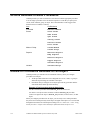
Actions Available to Build Procedures ................................................................................ 13-2
Review of Procedures Available for an Object .................................................................... 13-2
Procedure Configuration ...................................................................................................... 13-3
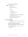
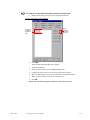
Opening the Procedure or Events Tab to Create a New Procedure........................ 13-3
Creating a New Procedure ..................................................................................... 13-4
Editing a Procedure................................................................................................ 13-9
Renaming an Object’s Procedure......................................................................... 13-11
Duplicating an Object’s Procedure ...................................................................... 13-11
Deleting an Object's Procedure............................................................................ 13-11
Defining Each Action .......................................................................................... 13-12
Configuring Advanced Properties for Procedures ............................................... 13-28
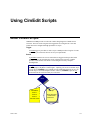
Using CimEdit Scripts
14-1
About CimEdit Scripts ......................................................................................................... 14-1
Script Configuration............................................................................................................. 14-3
Creating a CimEdit Script...................................................................................... 14-4
Accessing Script Entry Points................................................................................ 14-6
Invoking a CimEdit Script ..................................................................................... 14-7
Testing a CimEdit Script...................................................................................... 14-11
Basic Extensions for CimEdit Scripts ................................................................................ 14-12
Basic Extensions .................................................................................................. 14-13
Obsolete Basic Extensions................................................................................... 14-16
Contents-x
CIMPLICITY HMI CimEdit Operation Manual–July 2001
GFK-1396F
Taking Advantage of ActiveX Controls and OLE Objects
15-1
About ActiveX Controls....................................................................................................... 15-1
ActiveX Control Installation ................................................................................................ 15-2
ActiveX Control Insertion on a CimEdit Screen.................................................................. 15-2
Object Properties vs. ActiveX Control Properties................................................................ 15-3
Viewing an ActiveX Control's Standard Object Properties ................................... 15-3
Viewing the ActiveX Control Properties ............................................................... 15-4
ActiveX Controls and CIMPLICITY HMI Project Data ..................................................... 15-7
Configuring an ActiveX Trend Control: Example................................................. 15-7
Other OLE Objects............................................................................................................. 15-15
Opening an OLE Object that is inserted in a CimEdit Screen ............................. 15-15
Editing an OLE Object that is inserted in a CimEdit Screen ............................... 15-16
Converting an OLE Object that is Inserted in a CimEdit Screen ......................... 15-17
Using Point by Address
16-1
About Point by Address in CimEdit..................................................................................... 16-1
Point by Address Restrictions .............................................................................................. 16-2
Point by Address Description Configuration ....................................................................... 16-3
Point by Address Syntax ...................................................................................................... 16-5
Point by Address Security .................................................................................................... 16-6
Monitoring Point Attributes
17-1
About Point Attributes ......................................................................................................... 17-1
Appendix A - CimEdit Text File Syntax
A-1
Text File Format Syntax........................................................................................................ A-1
BNF Syntax............................................................................................................. A-2
Token Syntax ........................................................................................................ A-18
Appendix B - Managing CimEdit Screens
B-1
About Managing CimEdit Screens.........................................................................................B-1
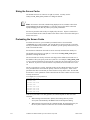
Screen Performance Issues.....................................................................................................B-1
Sizing Memory ........................................................................................................B-1
Sizing the Screen Cache...........................................................................................B-2
Preloading the Screen Cache....................................................................................B-2
Preventing Swaps to the Pagefile.............................................................................B-3
Adjusting the Touch Interval ...................................................................................B-3
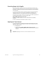
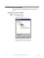
CimView Screen Installation .................................................................................................B-4
Installing A Screen from CimEdit ...........................................................................B-4
Opening a Screen from your Desktop......................................................................B-5
Command Line Options .........................................................................................................B-6
Adding Arguments to the Command Line for a CimView Shortcut........................B-6
Command Line Arguments ....................................................................................................B-7
Reviewing Options for CimEdit Shortcuts ............................................................B-15
Reviewing Options that can be Executed Interactively..........................................B-16
CimEdit/CimView GMMI_SCREENS Libraries.................................................................B-18
Editing GMMI_SCREENS Logical Name ............................................................B-18
Index
GFK-1396F
i
Contents
Contents-xi
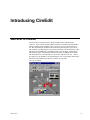
Introducing CimEdit
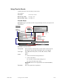
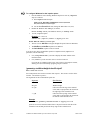
Welcome to CimEdit
You are about to reap the benefits of using CimEdit, with its runtime partner,
CimView—the first ActiveX HMI graphics container. The object oriented graphics
editing, CimEdit, and the runtime viewer, CimView, are easy to learn and easy to
use. They blend industry standards with advanced interface designs to provide you
with an intuitive package that lets you perform operations easily and naturally. Tight
integration of all CIMPLICITY functionality makes system design, configuration,
and operation simple. This package combines the power of CIMPLICITY software
with the Windows user interface that you are used to, right out of the box —there is
no complex set-up, installation, or programming to learn. Crisp graphics and smooth
animation make CimEdit and CimView a pleasure to work with.
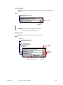
A Screen in CimEdit
GFK-1396F
1-1
CimEdit Tools
CimEdit provides a set of tools that let you graphically represent your facility.
Windows users will quickly notice the toolbars located around the screen. The
toolbars provide the drawing tools such as the capability to draw Line, Polyline,
Polygon, Rectangle, Ellipse, Arcs, Text and Button objects. CimEdit provides the
capability to import OLE and ActiveX objects into your screens. Trending, Quality
Charts, and Alarm Viewer are examples of CIMPLICITY ActiveX objects. Third
party OLE and ActiveX objects that can be embedded include Excel spreadsheets
and charts to bitmaps, video, and sound files. Once objects are created, they can be
resized, rotated or moved using the "handles" that appear when the object is selected.
With this combination of graphic tools, drawing graphic screens that accurately
depict a production process is very simple.
Once the objects are placed on the screen, another toolbar provides a powerful set of
alignment tools. Objects can be aligned automatically with a configurable grid, or
aligned as groups using the object alignment tools, which include the ability to space
objects evenly as well as align them in relation to each other. Objects can also be
rotated, flipped, grouped, or ungrouped.
Any object can then be animated using the object property sheet that pops up when
you double-click on an object or click on the property sheet icon on the forms
toolbar. This property sheet allows you to choose from a wide variety of animation
and control functions.
The animation properties of any object are displayed in a file tabular format that
allows you to navigate quickly between animation properties including: rotation, fill,
movement, color, and text annunciation, geometry, scaling, events, or the ability to
take an action using the procedure card from the property page.
1-2
CIMPLICITY HMI CimEdit Operation Manual–July 2001
GFK-1396F
CimEdit Features
CimEdit comes with an abundance of features to give you maximum ease and
flexibility when you configure the screens for your project. Some of these features
are:
§
Interactive, dynamic configuration allows you to add or modify point
configuration data from anywhere within CimEdit
§
A Point Browser dialog box gives you the ability to access any CIMPLICITY
point on the entire network, and use this point to animate an object.
§
Standard Object shapes are provided for use in your system, including squares
and rectangles, circles and ellipses, lines, polylines, arcs, pies, and cords.
Position, style, color, and rotation are some of the attributes that can be defined.
§
OLE and ActiveX embedded objects give your screens more power. Trend
charts, spreadsheet charts, multimedia presentations, and live motion video can
all provide power and extensibility to your system. OLE and ActiveX in-place
editing of embedded objects allows you to view your screen as a single
document without popping up other application windows. OLE and ActiveX
drag-and-drop support means you can just drag an OLE or ActiveX object from
one document to another. Drag Excel charts into CimEdit. Drag objects from
one CimEdit screen to another.
§
A Drag and Drop Library of over 2000 Symbols and SmartObjectä objects
makes creating screens a snap. The CIMPLICITY Object Explorer allows you to
easily drag and drop the symbols and SmartObjects into the screens you are
creating.
You can also add to the library by creating your own set of SmartObjects.
SmartObjects are easily created with standard CIMPLICITY objects through
Group Editing and Expression Variables. Group Editing provides the ability to
edit properties of objects within a group without ungrouping the objects.
Expression Variables provide the ability to use variables anywhere an
expression or point can be used. A variable can be replaced with either a string
or numeric value. The substitution of a variable can take place at either edit time
or at run time.
GFK-1396F
§
Movement and Rotation are two animations that can be performed on objects.
§
Filled Objects including fill from top, bottom, left, right, or bi-directional. Bidirectional fill is a unique feature that allows you to configure a single object,
which can fill in two directions from a center point. This is ideal for bipolar bar
graphs.
§
Interior and Border Animation provides you the ability to animate the internal
and outline aspects of objects. Interior Animation allows for color and pattern
changes. Border Animation changes the line surrounding the object.
Introducing CimEdit
1-3
§
1-4
Events can be configured to handle
è
Expression High, Expression Update
è
Key Down, Key Up
è
Mouse Down, Mouse Up
è
Object Inserted, Object Removed
è
Periodic
è
Screen Close, Screen Open
è
SmartObject
è
While Key Down
è
While Mouse Down
§
Frame Animation is a compound object that allows a series of frames to be
defined. Each frame can consist of different objects. A particular frame is
displayed based on the value of an expression. This allows areas of the screen to
change like a filmstrip.
§
Hold Last Value can be defined on a project basis. This feature allows you to
configure the system to hold the last known values of points in your CimView
screens if the points go into an Unavailable State. Text points in this state will
display in a configured color (determined for the entire project).
§
Metafile Import allows Windows Metafile objects produced by programs such
as AutoCad and PowerPoint to be cut and pasted into CimEdit. The imported
images can be decomposed into CIMPLICITY objects and can be fully
animated. This is in contrast to bitmap imports that remain as single static
objects.
§
Point Search & Replace allows you to search the screen for a point and
highlight all objects that contain the point. You can then replace point identifiers
within a CimEdit screen by simply typing over the name in a list of points used
in the screen.
§
Scalable Objects provides the ability to change the size of an object based on
the value of a point. The object can be scaled independently in the X and Y
directions.
§
Scripting allows Basic Control Engine Scripts to be run from a CimView
procedure.
§
Undo/Redo allows you to undo and redo a series of modifications to graphic
screens.
§
Visibility Animation allows an object’s visibility to be controlled by an
expression. If an object is invisible, it cannot be selected.
§
Online Help provides comprehensive, indexed documentation, which is just a
keystroke away at any time.
§
Object Help can be configured for any object on the screen. The operator can
then access this help at any time using the right mouse button.
§
Dynamic Screen Testing allows you to test screen-editing changes in CimEdit
without changing your original screen. By using the Test button on the standard
menu bar, you can automatically start a CimView window to view your edits
without committing to them.
CIMPLICITY HMI CimEdit Operation Manual–July 2001
GFK-1396F
A Word about CimView
CimView is the powerful, graphics runtime portion of CIMPLICITY HMI where the
features you used in CimEdit come to life. Powerful animation techniques give
smooth, flicker-free animation to your graphic screens. With CimView, you will see
your process information displayed in both textual and graphic format. Alarms, video
clips, pop-up windows, and the large selection of animation features help you
transform your process data into process information, allowing you to improve your
quality, productivity, and profitability.
With CimView you can:
§
View powerful graphic and text information.
§
Access powerful scripts by pressing a key or clicking on an object.
§
Get a description of the animation and actions associated with an object with a
click of the mouse.
§
Display Help text with a click of the mouse.
§
Display screens from other applications via OLE Automation.
Using CimEdit's Dynamic Screen Testing, you can review what CimView will
display as frequently as you want.
GFK-1396F
Introducing CimEdit
1-5
Opening CimEdit
About Opening CimEdit from the Workbench
The CIMPLICITY HMI Workbench offers you familiar features (also found in Windows
Explorer) for opening new and existing CimEdit screens.
This chapter reviews the methods available to you for:
•
Opening a new CimEdit screen.
•
Open an existing screen to edit.
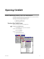
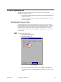
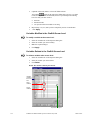
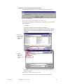
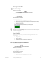
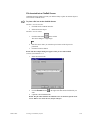
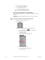
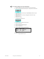
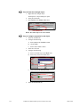
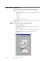
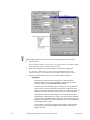
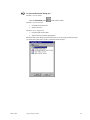
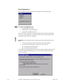
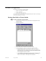
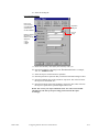
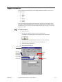
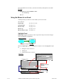
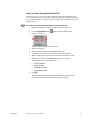
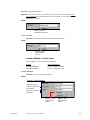
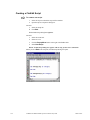
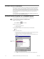
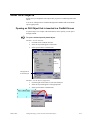
Opening a New CimEdit Screen
There are several ways to open a new CimEdit screen.
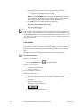
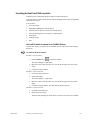
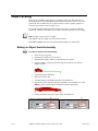
To open a new CimEdit screen:
1.
Select Screens in the left pane of the Workbench.
Method 1–Use a quick method
Double-click Screens.
Method 2–Use the popup menu
GFK-1396F
2.
Click the right mouse button.
3.
Select New from the popup menu.
2-1
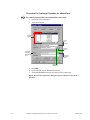
Method 3–Use the Workbench menu bar
2.
Select Screens in the left pane of the Workbench.
3.
Clock File on the Workbench menu bar.
4.
Select New.
5.
Select Object.
Method 4–Use the keyboard
2.
Select Screens in the left pane of the Workbench.
3.
Press ALT+F on the keyboard.
The drop down File menu opens.
4.
Press N on the keyboard.
5.
Press O.
Method 5–Use the keyboard
Press Ctrl+N on the keyboard.
Result: A new CimEdit screen opens when you use any of the five methods.
2-2
CIMPLICITY HMI CimEdit Operation Manual–July 2001
GFK-1396F
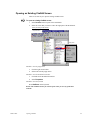
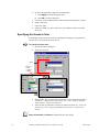
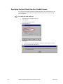
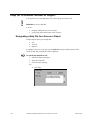
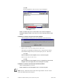
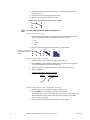
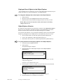
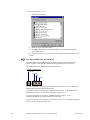
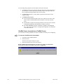
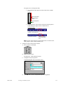
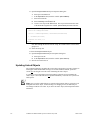
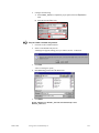
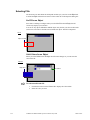
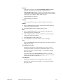
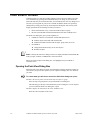
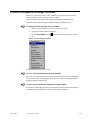
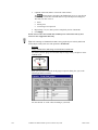
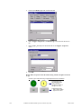
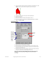
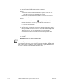
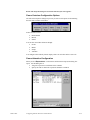
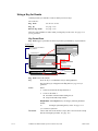
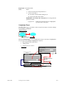
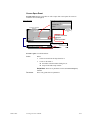
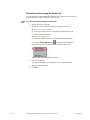
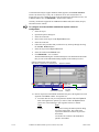
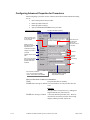
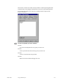
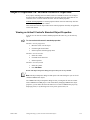
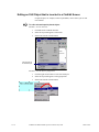
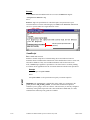
Opening an Existing CimEdit Screen
There are several ways to open an existing CimEdit screen.
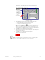
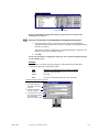
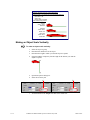
To open an existing CimEdit screen:
1.
Select Screens in the left pane of the Workbench.
2.
Select the screen that you want to edit in the right pane of the Workbench.
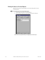
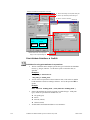
Opening an Existing CimEdit Window
Drop down menu
Popup menu
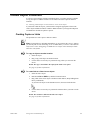
Method 1–Use the popup menu
3.
Click the right mouse button.
4.
Select Edit from the popup menu.
Method 2–Use the Workbench menu bar
3.
Click Edit on the Workbench menu bar.
4.
Select Properties.
Method 3–Use the keyboard
Press Alt+Enter on the keyboard.
Result: The CimEdit window you selected opens when you use any of the three
methods.
GFK-1396F
Opening CimEdit
2-3
Reviewing CimEdit Configuration
CimEdit Configuration Overview
CimEdit combines the features commonly found in high-powered graphics applications,
with an abundant number of state of the art configuration tools. They all help you take
advantage of CIMPLICITY HMI’s extensive runtime capabilities. Consequently, you can
create CimView screens that are clear, easy, and robust.
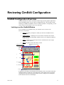
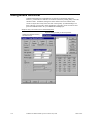
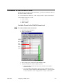
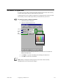
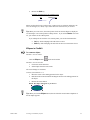
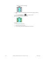
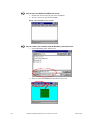
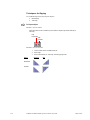
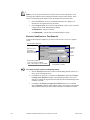
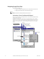
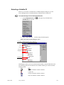
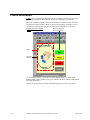
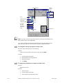
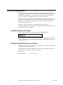
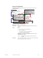
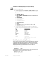
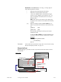
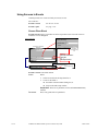
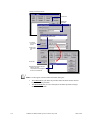
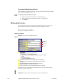
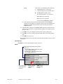
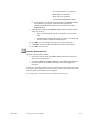
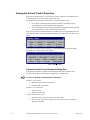
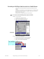
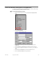
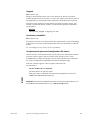
Looking over the CimEdit Window
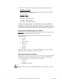
As you configure your CimEdit screen, you will work on two or more levels.
The levels are as follows:
§
Screen–the primary workspace in which you create the CimEdit/CimView
configuration.
§
Frame container –containing two or more frames. Each frame can contain
groups and/or objects that display when the frame’s pre-configured conditions
evaluate to True.
§
Group–a collection of several objects that are combined to act like a single
object in certain instances.
§
Object–the primary item with which you work.
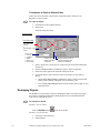
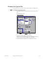
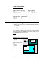
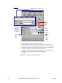
CimEdit Screen Example
Minimize/Maximize/Restore/Close
Buttons
Control Menu
Button
Menu Bar
Toolbars
1
Screen
2
Frame
3
Text + Button
= a Group
4
(Text) Object
Status Bar
In addition to providing you with high-powered graphics tools in its toolbars and menus,
CimEdit provides you with easy to use dialog boxes. These dialog boxes are powerful
enough for the most sophisticated programmers and easy enough for screen designers
whose abilities lean more toward design. .
GFK-1396F
3-1
Reviewing Configuration Steps
If you are designing screens in CimEdit that will be used during runtime in CimView,
you are probably a system administrator, engineer and/or screen designer. That means
you know how to add one simple element to another until you create, what can be, an
elaborate and complex final product.
You design CimEdit screens the same way. Although your completed CimEdit screens
will provide your plant with unprecedented monitoring power, developing them is a
systematic process. Because each step is self-contained, you can jump around as much as
you want.
When you begin to plan how CimView will monitor, evaluate, and report on the status of
your system’s processes, there are some basic factors to consider.
They include:
§
§
3-2
Information requirements for CimView
è
Choosing data sources.
è
Determining user interaction needs.
è
Determining where runtime information will be used.
CimEdit configuration choices
è
Estimating the number of screens that are needed.
è
Selecting CimEdit objects that will convey the information most effectively.
è
Choosing which CimEdit processes will unleash the power of the objects.
è
(Optional) Adding ActiveX and third party objects.
CIMPLICITY HMI CimEdit Operation Manual–July 2001
GFK-1396F
Information Requirements for CimView
How you design your CimEdit configuration depends on your project’s information
requirements. Therefore, your planning begins with determining those requirements. The
requirements include:
§
Choosing data sources.
§
Determining user interaction needs.
§
Determining information destinations.
Choosing Data Sources
Information that CimView displays, calculates, and monitors can come from a wide
variety of sources.
Sources include:
§
Point data.
§
Variables.
§
Expressions.
§
Other data sources.
Point Data Sources for CimView
Point values are at the core of CimView monitoring and regulation of processes.
Points defined in CIMPLICITY’s Point Configuration application are readily
available whenever you need them in CimEdit. In addition, if you need to create new
points you can easily open the Point Configuration application through CimEdit.
§
Device Point values from PLCs or other devices provide the CimView viewer
with the ability to monitor a process represented by several points.
§
Virtual Points provide a flexible way to create calculated values.
Two common uses for a point are:
§
Setpoints to affect a process.
§
Alone or in expressions to display information about a process.
Variables as Data Sources within CimView
Variables are flexible containers for information and do not add to your project’s
overhead. A variable has a unique name, a variable ID, and represents a value that can be
assigned to it during configuration of the CimEdit screen or at runtime.
Some of the data sources it can represent are:
GFK-1396F
§
Full Point ID
§
Partial Point ID
§
Text string in an expression.
Reviewing CimEdit Configuration
3-3
A variable does not communicate with the PLC but is wholly contained in CimEdit.
Example of a Variable
Different values (types of values) are assigned to a variable ID {var_value} for
different items on a CimEdit screen.
Variable ID Value
var_level 40
var_level tank_level (point)
var_level tank_level+50
var_level Assigned during runtime
In addition to providing you with several options for assigning values, variables can
streamline your configuration time. For example, when you create an object that uses
variable IDs, you can use the same object in several locations on a CimEdit screen, or on
several different screens and assign different text strings to each instance of the object.
Expressions as Data Sources for CimView
Expressions provide a valuable and flexible way to help you evaluate, compare, and use
the information gathered by points or variables or both.
An expression includes points, variables, or both along with any of the following
CimEdit operations:
§
Arithmetic
§
Logical
§
Alarm functions
§
Bitwise
§
Conversion
§
Relational
§
Scientific
CimEdit provides you with an easy to use Expression dialog box, in which you build
complicated expressions with just a few clicks of the mouse.
Other Data Sources for CimView
Although points, variables, and expressions are sources for the most current information
in CimView, you may need to view logged, historical, or other types of information.
These values can come from vast number of sources, including:
§
Logged files
§
Text files
§
Other database type files
Note: These data sources are available through features, such as Trending, or scripts.
3-4
CIMPLICITY HMI CimEdit Operation Manual–July 2001
GFK-1396F
Determining User Interaction with CimView Screens
CimView provides you with the framework to take full advantage of CIMPLICITY
HMI’s powerful setpoint capabilities.
These capabilities include enabling CimView users to change device point values in a
PLC to turn a machine on/off, open/close valves, or increase/decrease values to control
how processes will function.
Determining where Runtime Information will be used
If you have more than one CimView viewer, it is a good idea to lay out what information
needs to be displayed and what type of user interaction is required at each location. The
number and type of locations may be a major factor in how the screen design will be
most effective.
For example, locations can be as disparate as being on:
GFK-1396F
§
On one or more Viewers in the network.
§
Remote, with a user accessing the CIMPLICITY HMI project through
WebView.
§
Remote, with a user accessing the CIMPLICITY HMI project through
PocketView on a handheld PC.
Reviewing CimEdit Configuration
3-5
CimEdit Configuration Choices
CimEdit offers you a number of tools and features to help you design the CimView
screens that will work most effectively in your organization. The choices you make
depend, of course, on your project’s information requirements. You also have the
flexibility to cater to your own and the users’ design preferences.
The basic issues you will deal with are to determine the:
§
Estimated number of screens for the project.
§
Objects that will convey CimEdit data.
§
CimEdit processes that will unleash the power of the objects.
§
(Optional) ActiveX and third party objects that may enhance CimView’s
capabilities.
Estimating the Number of Screens for a Project
When you have determined your information requirements, you can estimate the number
of screens that need to be designed. The number will be influenced by the:
§
Anticipated number of viewer destinations that require different screens
§
Type and number of monitoring and regulating tasks that can be divided into
logical units
§
Amount of information to be displayed, keeping in mind that displays need to be
clear to view in a runtime environment
Note: Using frames is another layout option if you have several objects on a screen that
will change during runtime, based on a similar set of conditions. See the “Configuring
Runtime Movement and Animation” chapter in this manual for detailed information
about configuring frames.
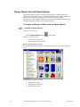
Selecting Objects to Convey CimView Data
CimEdit provides you with a huge variety of objects to contain, display, and let the
CimView user act on the data flowing to, from, and within it.
Objects include:
3-6
§
Basic graphic shapes that you create.
§
Text objects.
§
Wide variety of SmartObjects from CimEdit’s Object Explorer.
§
OLE objects.
§
Picture objects (Metafiles) converted by you into to CimEdit objects.
§
Entire AutoCad drawings imported as a set of CIMPLICITY HMI objects.
§
ActiveX controls including the CIMPLICITY Alarm Viewer and Trend chart.
CIMPLICITY HMI CimEdit Operation Manual–July 2001
GFK-1396F
These objects may be a:
§
Single element, such as a text message
§
Pre-configured group of objects, such as most objects in CimEdit’s Object
Explorer
§
Group of objects combined by you
CimEdit also provides you with a huge variety of tools as toolbar buttons and menu items
to change the object’s appearance. This includes changing its:
§
Size.
§
Shape.
§
Angle of rotation.
§
Color and fill.
Another time saving feature provided by CimEdit is the ability to create linked objects.
Linked objects save you valuable time by providing you with the ability to change a
single object, the linked object, and then let CIMPLICITY HMI finish the job of updating
every link to that linked object, in your entire project.
In addition, this single source capability insures that any specification or change made to
the linked object will be reproduced exactly in every link to that linked object.
By mapping out the data flow, you can narrow down your choice of objects for each
CimEdit task. Because each configuration is composed of a series of small steps, you can
easily change your mind as you begin configuration.
Unleashing the Power of CimView
When objects are laid out you are ready to make them work for you.
Anything on the screen, including the screen, can be involved in actions that occur
§
Within CimEdit, for example, another screen can be opened.
§
A machine or process can be turned on and off or regulated.
Objects can also be used to monitor plant processes, including:
§
Normal operations
§
Alarm states
§
Trends
It is in this phase of configuration that you will involve various types of data. What you
want each object to represent and do will determine which type you use.
You may have placed some of the objects on your CimEdit screen to promote one or
more actions. The screen, itself, can also be involved.
GFK-1396F
Reviewing CimEdit Configuration
3-7
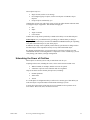
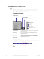
Process for Triggering Actions in CimView
The process is straightforward, involving a:
Trigger
An event triggers a procedure or calls a script. CimEdit provides a long list of events
from which you can choose the best one for your requirements.
Result
A procedure is one or more actions that are triggered in the specified order when an
event occurs and while the screen is displayed in CimView. CimEdit provides
several actions from which a screen designer can easily compile a meaningful list.
A script, which is usually written by a system administrator, uses the same Editor
and Basic language as the Basic Control Engine. Anything you can do in a normal
script, you can do in a CimEdit script. CimEdit provides additional extensions to
give you a wider range of screen development choices. However, CimEdit scripts
are only accessible from the screen in which you create them.
Event
Procedure
Script
Action 1
+
+
Action n
+
Action 2
Basic language
+CIMPLICITY
extensions
Terminal Action
Options for Monitoring Processes in CimView
CimEdit provides several choices to create activity on your screens that make if easy for
a CimView user to quickly determine the status of a point or expression. Items can:
§
Move.
§
Rotate.
§
Change in size.
§
Fill up.
§
Change color and text through animation.
Items can be:
3-8
§
Groups.
§
Objects.
§
Text.
§
Lines.
§
Shapes.
CIMPLICITY HMI CimEdit Operation Manual–July 2001
GFK-1396F
Each configuration involves a few simple arithmetic calculations. Combining or nesting
activities requires only the simple configuration that you do for each.
Your options depend only on the requirements for your project, your ingenuity, and
system resources.
Adding ActiveX and Other Objects
Because CimEdit provides you with ActiveX objects, such as Trend and XY charts, as
well as the ability to use such diverse items as entire CAD drawings you may need to do
more configurations. Simply continue in the same systematic manner.
GFK-1396F
Reviewing CimEdit Configuration
3-9
Dialog Boxes Overview
CimEdit configuration is accomplished in several tabs of a Properties dialog box.
However, you will discover that there is an internal consistency making many of the tabs
similar to others. In addition, dialog boxes at the different levels in CimEdit, from
screens to objects have many of the same tabs. Consequently, by understanding a few
basic concepts, you can easily do the configuration you need to create an effective and
powerful CimEdit interface for your CIMPLICITY HMI project.
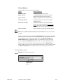
Sample of Easy to Fill in tabs Found in CimEdit Dialog Boxes
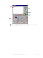
Expression dialog provides you with the operators.
Fills/Movement/Rotation/Scaling
are similar to fill in
3-10
CIMPLICITY HMI CimEdit Operation Manual–July 2001
GFK-1396F
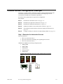
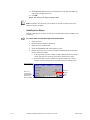
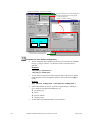
CimEdit Screen Configuration Example
Following is a simple CimEdit configuration example. It begins with determining some
information requirements for a process and continues with configuring screen for
CimView that will address the information requirements.
Procedures can be grouped into six steps for basic configuration.
Steps include:
Step 1.
Determine the information sources. See page 3-11.
Step 2.
Determine any required user interaction. See page 3-12.
Step 3.
Determine the information destinations. See page 3-12.
Step 4.
Estimate the number of screens that will be needed. See page 3-13.
Step 5.
Select and layout objects that will effectively display the information. See
page 3-14.
Step 6.
Configure each object to function as required during runtime. See page 3-15.
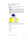
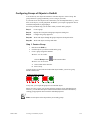
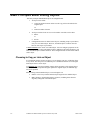
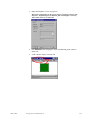
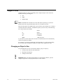
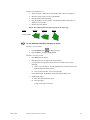
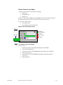
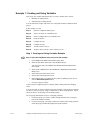
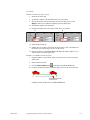
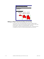
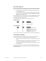
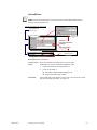
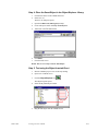
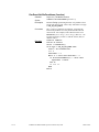
Step 1. Determine the Information Sources
There are three PLCs.
1.
PLC 1 is connected to Tank 1.
2.
PLC 2 is connected to a throttling valve regulating flow to Tank 1.
3.
PLC 3 is connected to Tank 2.
CIMPLICITY HMI has the following configured points:
1.
Tank1_Level
2.
Tank1_Temp
3.
Tank1_Flow
4.
Valve_Piston
5.
Tank2_Flow
Example: Some Information Sources for which CimEdit will be Configured
PLCs
Level
GFK-1396F
Temperature
Reviewing CimEdit Configuration
Flow
3-11
Step 2. Determine any Required User Interaction
On Viewer 1
Users need to regulate the valve piston opening through PLC 2.
Step 3. Determine the Information Destinations
There are two Viewers.
CimView users need to:
On Viewer 1
1.
Monitor the current level of Tank 1.
2.
Monitor the current temperature of Tank 1.
3.
View a Tank 1 level trend.
4.
View a Tank 1 temperature trend.
5.
Monitor the rate of flow out of the Tank 1 valve (into Tank 1).
On Viewer 2
3-12
6.
View the percent level in Tank 2.
7.
View the rate of flow to Tank 1.
CIMPLICITY HMI CimEdit Operation Manual–July 2001
GFK-1396F
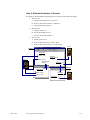
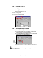
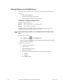
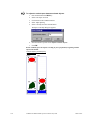
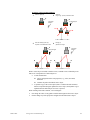
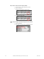
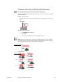
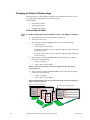
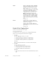
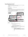
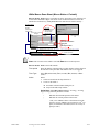
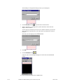
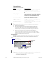
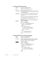
Step 4. Estimate the Number of Screens
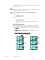
In response to the information requirements, three CimView screens will be designed.
1.
Screen 1 will:
A. Display as the main screen on Viewer 1.
B. Receive device data from PLC 1 and PLC 2.
C. Send setpoint input to PLC 2.
2.
Screen 2 will:
A. Display on Viewer 1.
B. Be opened through Screen 1.
C. Receive device data from PLC 1.
3.
Screen 3 will:
A. Display on Viewer 2.
B. Receive data from Screen 1 (Tank 1 flow).
C. Receive device data from PLC 3 (Tank 2 flow)
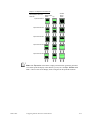
PLC 2
Screen 1
View points
1
Tank1_Level
Regulate
Valve_Piston
2
6
Tank1_Temp
PLC 1
Move between
Screen 1
View point
Tank1_Flow
5
Screen 2
Screen 3
View trends Screen 2
3
4
8
Tank1_Temp
Tank1_Level
View point
Tank2_Flow
GFK-1396F
Reviewing CimEdit Configuration
PLC 3
View point
Tank1_Flow
7
3-13
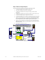
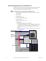
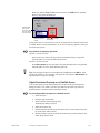
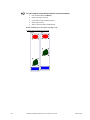
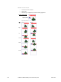
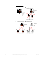
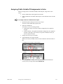
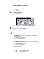
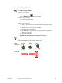
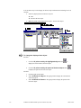
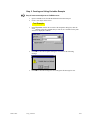
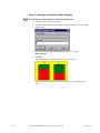
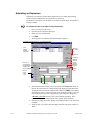
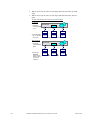
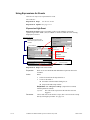
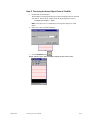
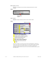
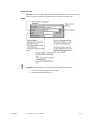
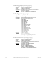
Step 5. Select and Layout Objects
Objects that will effectively display the information requirements include:
1.
A CimEdit SmartObject tank to display the Tank 1 level.
2.
A text object to display the exact Tank 1 temperature.
3.
A CIMPLICITY HMI ActiveX trend object to display a trend of Tank 1
temperatures.
4.
A CIMPLICITY HMI ActiveX trend object to display a trend of Tank 1 levels.
5.
A CimEdit SmartObject gauge to display the Tank 1 flow.
6.
A CimEdit SmartObject lever to enable user setpoint action for the valve piston.
7.
A space is reserved on Screen 3 for a copy of the CimEdit SmartObject gauge.
To save time, this object will be copied after it is fully configured. Settings can
then be changed after the object is copied to apply the object to Tank 2.
8.
A space is reserved on Screen 3 for a linked copy of the CimEdit SmartObject
gauge after it is fully configured. The gauge display will be the same on Screen
3 as it is on Screen 1.
9.
Text buttons to open Screens 1 and 2.
PLC 2
Screen 1
1
Tank1_Level
Tank 1 View
(title will be linked)
Wizard
6
Valve_Piston (setpoint)
PLC 1
2
Tank1_Temp
Temperature
Normal
Object will be linked
Wizard
5
Tank1_Flow
Screen 2
Screen 2
3
4
Screen 1
Reserved for
title link
Tank1_Temp
CimEdit
ActiveX
Tank1_Level
Trend
Screen 3
Reserved for
title link
Reserved
for copy
(of 5)
3-14
8
PLC 3
Reserved for
link (of 5)
7
Tank2_Flow
CIMPLICITY HMI CimEdit Operation Manual–July 2001
GFK-1396F
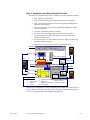
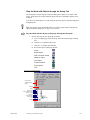
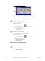
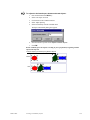
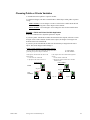
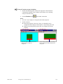
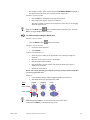
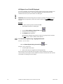
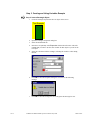
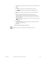
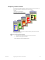
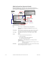
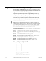
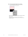
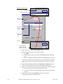
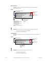
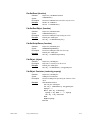
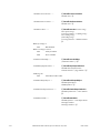
Step 6. Configure each Object Runtime Function
The objects are configured using some of CimEdit’s powerful configuration features.
1.
Tank 1 tank uses the fill feature.
2.
Tank 1 temperature changes through Expression and color animation.
3.
Tank 1 temperature trends are the result of configuring the CIMPLICITY
HMI ActiveX trend object.
4.
Tank 1 level trends are the result of configuring the CIMPLICITY HMI
ActiveX trend object.
5.
The Tank 1 SmartObject gauge uses rotation.
6.
The Level for the valve piston setpoint uses the movement feature.
7.
The reserved place for a copy of the gauge uses rotation with criteria
modified to reflect Tank 2.
8.
The reserved place for a link container on Screen 3 displays the link to the
SmartObject gauge on Screen 1.
9.
Buttons to open each screen are activated by a Mouse up event.
PLC 2
Screen 1
Tank 1 View
1
Tank1_Level
6
Valve_Piston (setpoint)
PLC 1
2
Tank1_Temp
5
Temperature
Alarm High
9
Tank1_Flow
Screen 2
Screen 2
Tank 1 View
Screen 3
Screen 1
3
Tank 2 View
Tank1_Temp
4
Trend
Tank1_Level
8
PLC 3
Tank1_Flow
7 Tank2_Flow
Configuration Features
1 Fill
2 Color animation
3 ActiveX
4 ActiveX
5
6
7
8
Rotation linked object
9 Mouse up event /
Movement
Open Screen action
Rotation (Copied object)
Link container
This powerful configuration was done through simple and similar tabs in each object's (or
screen’s) Properties dialog box. The dialog box is accessed by double-clicking the object
(or screen). It could also have been configured through scripts.
GFK-1396F
Reviewing CimEdit Configuration
3-15
Configuring a CimEdit
Screen
About CimEdit Screens
Your CimEdit screen provides you with several diverse features and capabilities that you
can use at any time during your screen design session. These features enable you to:
§
§
Alter the screen's appearance.
è
Screen color, fill, pattern, and border
è
Screen size
Use workspace aids.
è
Grid display
è
Mouse location status
è
Toolbar selection and descriptions
§
Create variables that are available to all objects.
§
Create procedures that are available to objects in any direct path from the screen
down.
§
Create scripts that are available to all objects.
§
Apply ambient properties.
§
Add your own Help for the screen (simple text help or full Window help.
§
Create popup menu items.
§
Name the screen.
§
Save the screen as a runtime only file.
The screen has its own Properties dialog box and an Options dialog box to accommodate
its unique position within the CimEdit workplace.
This chapter describes all the screens features and capabilities. However, features such as
selecting colors, will only be addressed briefly. This is because the basic procedure is the
same as for any object and is discussed in great detail later in the manual.
GFK-1396F
4-1
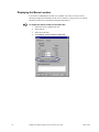
Accessing the Screen Properties
There are several ways to open the Properties dialog box.
To open the screen's Properties dialog box:
Method 1
1.
Click Format on the menu bar.
2.
Select Screen Properties.
Method 2
1.
Make sure all the objects on the screen are deselected
2.
Click Edit on the menu bar.
3.
Select Properties.
Method 3
1.
Hold down the right mouse button.
2.
Select Properties from the drop-down menu over a portion of the screen that has
no objects.
Result: The Properties dialog box opens when you use any of these methods.
4-2
CIMPLICITY HMI CimEdit Operation Manual–July 2001
GFK-1396F
Screen Appearance
Because the screen is the background for your work, by the time you finish the
configuration it will have to be:
§
Large enough to contain all the objects you have placed, but small enough to fit
easily on the viewers.
§
Colored or filled with a solid color, gradient, or pattern that will focus viewers’
attention on the objects.
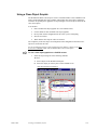
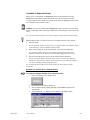
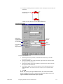
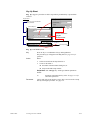
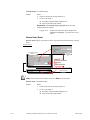
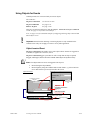
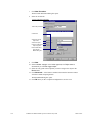
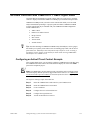
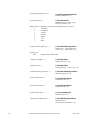
Specifying the Screen’s Size
You can change the size of the screen as frequently as you want. If your viewers have
different resolutions or want to enlarge the screen by using the zoom feature, it is a good
idea to test the size before you go too far placing and resizing the objects.. In order to
insure that text and images will be the size you believe is most effective, as a rule of
thumb, the actual screen size (Zoom 100%) should fit comfortably on any viewer where
it will be used.
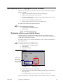
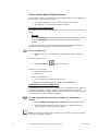
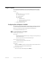
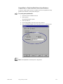
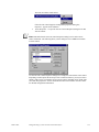
To specify a screen’s size:
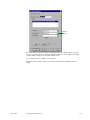
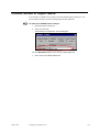
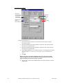
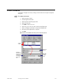
1.
Open the Properties dialog box.
2.
Choose the Geometry tab.
Apply is activated when a
dimension is changed
3.
Enter the screen dimensions you want to use in the Width and Height fields.
See "Object Form" in the "Applying Inanimate Visual Features" chapter in this
manual.
GFK-1396F
Configuring a CimEdit Screen
4-3
4.
Do one of the following to apply the new dimensions:
A. Click Apply to keep the dialog box open.
B. Click OK to close the dialog box.
5.
Click View on the CimEdit menu bar when the Properties dialog box is closed
6. Select Zoom 100%.
7.
Click View again.
8.
Select Size Window to Zoom. This resizes your window to fit the new actual
screen size.
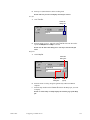
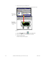
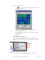
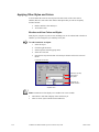
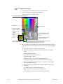
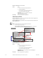
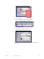
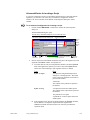
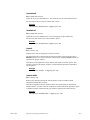
Specifying the Screen’s Color
Even though you specify the screen color in the Properties dialog box, the procedure is
the same as it is for most objects on the screen.
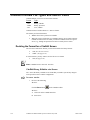
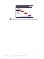
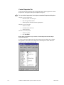
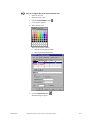
To specify a screen color:
1.
Open the Properties dialog box.
2.
Select the Colors tab.
Border
Select one:
Solid
Gradient
Pattern
3.
Select the line style you want in the Line section, if you want the screen to have
a border. See “Applying Other Styles and Colors” in the “Applying Inanimate
Visual Features” chapter in this manual.
4.
Select the fill type and color(s) for that type in the Fill section. See “Color and
Fill Selection” in the “Applying Inanimate Visual Features” chapter in this
manual.
Note: Arrowheads and Closed are disabled for the screen border.
4-4
CIMPLICITY HMI CimEdit Operation Manual–July 2001
GFK-1396F
Workspace Aids Displayed on the Screen
While you are working on your CimEdit screen you can choose several aids to display or
hide. They include:
§
A grid of horizontal and vertical lines across your workspace.
§
Display of the mouse location in the status bar.
§
A variety of toolbars and tool tips that identify a toolbar button when you move
the cursor over the button.
§
Tools to zoom the CimEdit screen display size.
§
Option to specify the undo stack size for a CimEdit screen.
You choose these options in the Options dialog box.
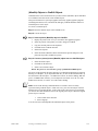
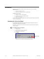
To open the Options dialog box:
1.
Click Tools on the CimEdit menu bar.
2.
Select Options…
Result: The Options dialog box opens.
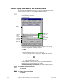
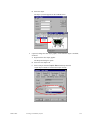
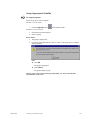
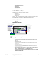
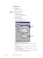
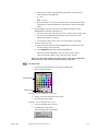
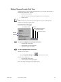
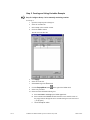
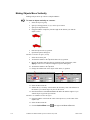
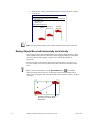
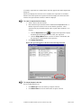
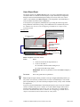
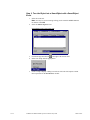
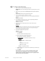
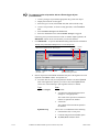
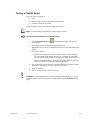
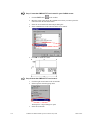
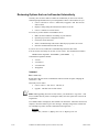
Displaying a Grid on your CimEdit Screen
CimEdit provides you with the option to display a grid on your CimEdit screen and
features of the display. The grid is one of many tools that help you place and align objects
exactly where you want them to appear.
See “Object Layout” in the “Creating a Preliminary Layout” chapter of this manual for
other alignment tools.
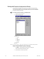
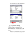
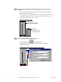
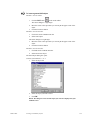
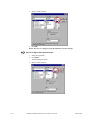
To display a grid on the CimEdit screen:
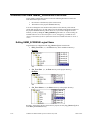
1. Click Tools on the CimEdit menu bar.
2.
Select Options…
3.
Select the General tab.
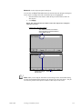
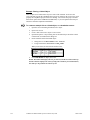
Specifications for a Grid Display
Object will snap
to the nearest
grid dots or line
when you release
the mouse button
Space between
lines horizontal and
vertical
Check if or how the grid
should display
4.
Choose if and how the grid should display.
5.
Enter the number of points (default CimEdit measurement) between horizontal
and vertical lines.
6. Check Snap to grid if you want the object to snap to the nearest grid.
Snap to grid affects the selected object. When you move an object, resize it, or reshape it.
GFK-1396F
Configuring a CimEdit Screen
4-5
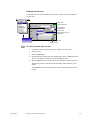
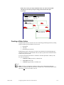
Displaying the Mouse Location
You can have CimEdit display at what X,Y coordinate your cursor is on the screen by
choosing to display the information on the screen’s status bar. This provides you with the
numbers to make precise calculations about placement and size.
To display the mouse location in the status bar:
4-6
1.
Click Tools on the CimEdit menu bar.
2.
Select Options…
3.
Select the General tab.
4.
Check Display mouse location in status bar.
CIMPLICITY HMI CimEdit Operation Manual–July 2001
GFK-1396F
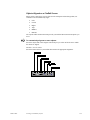
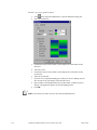
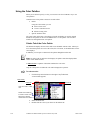
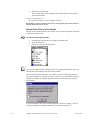
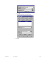
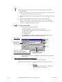
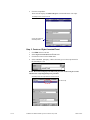
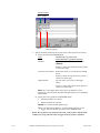
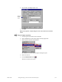
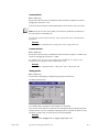
Choosing What Toolbars to Display
CimEdit provides you with several toolbars that you can display when you need them and
hide to increase your workspace. In addition, you can choose to display tips that will
describe each button when you hold your cursor over it.
The toolbars are:
Standard
Tool
Format
Layout
OLE
Standard
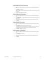
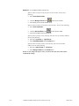
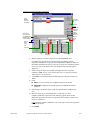
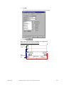
To choose what toolbars to display or hide:
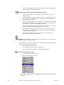
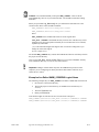
1.
Click Tools on the CimEdit menu bar.
2.
Select Options…
3.
Select the Toolbars tab.
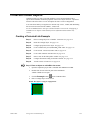
Toolbar and Tips Display
GFK-1396F
4.
Check the toolbar checkboxes to display the toolbar.
5.
Check Show tool tips to display a description of a button when you move your
cursor over it.
Configuring a CimEdit Screen
4-7
Zooming the CimEdit Screen Display Size
CimEdit offers you several methods to magnify or reduce your CimEdit display size
during configuration.
When you have zoomed the screen, you can fit the window to the zoom.
Note: These methods are for display in CimEdit. To change the display of the CimView
screen, enter the screen dimensions on the Geometry tab of the Properties dialog box.
To zoom the screen, choose either:
Method 1. CimEdit toolbar buttons
Method 2. A quick zoom percent displaying on the CimEdit Edit menu
Method 3. Precise zoom from the CimEdit Zoom dialog box
Then
Continue. Fit the window to the new workspace display size.
To change a CimEdit screen display size during configuration:
Method 1. Use CimEdit toolbar buttons
Click either the:
§
Zoom 100 button
CimView.
§
Full Screen button
to zoom the screen to the size it will display in
to use the entire monitor screen for display.
Press ESC on the keyboard to return to the CimEdit window environment.
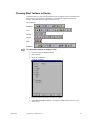
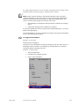
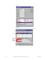
Method 2. Use the zoom percents on the CimEdit Edit menu
1.
Click View on the CimEdit menu bar.
2.
Select the percent you want the display to zoom from one of the percent choices.
Edit Menu: Zoom Percent Selected
Choose percent screen
will zoom.
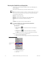
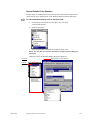
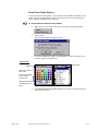
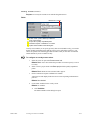
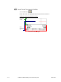
Method 3. Enter a precise zoom percent
4-8
1.
Click Edit on the menu bar.
2.
Select Zoom.
CIMPLICITY HMI CimEdit Operation Manual–July 2001
GFK-1396F
Edit Menu: Open Zoom Dialog Box
Open Zoom
dialog box
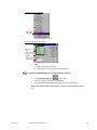
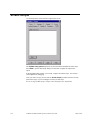
The Zoom dialog box opens.
Zoom Dialog Opened Through Edit Menu
Percent screen
zoom
Screen expands
or contracts to fit
workspace
Enter an exact
percent zoom
3.
Either:
A. Select one of the zoom choices.
B. Enter a precise zoom percent in the Percent field.
To fit the CimEdit window to a zoomed display, choose:
§
Click the Zoom to fit button
§
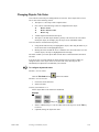
Select Size Window to Zoom on the Edit menu
§
Check the Zoom to fit window radio button on the Zoom dialog box.
on the toolbar
Result: The CimEdit window will expand or contract to fit the workspace display
size.
GFK-1396F
Configuring a CimEdit Screen
4-9
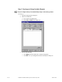
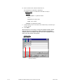
Specifying the Undo Stack Size for a CimEdit Screen
You can specify how much information CimEdit should keep in an undo stack before the
oldest information is discarded. This stack size determines how much you can undo in
your configuration.
To specify the undo stack size:
1.
Click Tools on the CimEdit menu bar.
2.
Select Options.
The Options dialog box opens.
4-10
3.
Select the Edit tab.
4.
Enter either:
§
A number between 0.001 and half the currently available page file memory.
§
Zero (0) to disable the undo feature.
CIMPLICITY HMI CimEdit Operation Manual–July 2001
GFK-1396F
Variables at the Screen Level
Because the screen is at the top of the data hierarchy, you can create variables at this level
that will be available to all objects.
See “Variable Evaluation Hierarchy” in the “Using Variables” chapter of this manual.
At the CimEdit screen level, you can:
§
Create variables.
§
Modify variables.
§
Delete variables.
Variables Created at the CimEdit Screen Level
To create variables at the screen level:
1.
Open the Properties dialog box.
2.
Select the Variables tab.
Variables
created at
the screen
level
Public
variables
Private
variables
Expression dialog box
GFK-1396F
3.
Enter a unique name (variable ID) in the Variable column.
4.
To specify whether the variable is public or private:
§
Check the Public column if the value of the variable can be entered at
different locations.
§
Leave the Public column blank to specify a private variable–the value of
the variable can not be changed at different locations. See “Choosing Public
or Private Variables” in the “Using Variables” chapter in this manual.
Configuring a CimEdit Screen
4-11
5.
(Optional at this time) Enter a value in the Value column.
Two buttons
appear at the right of the Value field you are in. Use them
to find existing or create new Point Ids, and/or to open the Expression dialog
box. The value you enter can be a:
6.
7.
§
Point ID
§
Partial Point ID
§
An expression that can include a text string
Repeat Steps 3–4 (or 5) until you have completed your list of variable IDs.
Click Apply.
Variables Modified at the CimEdit Screen Level
To modify a variable at the screen level:
1.
Select the Variables tab of the Properties dialog box.
2.
Select the variable you want to modify.
3.
Make the required changes.
4.
Click Apply.
Variables Deleted at the CimEdit Screen Level
To delete a variable at the screen level:
1.
Select the Variables tab of the Properties dialog box.
2.
Select the variable you want to delete.
3.
Click Delete.
Result: The variable is deleted from the list.
Variables
created at
the screen
level
Public
variables
Private
variables
Expression dialog box
4-12
CIMPLICITY HMI CimEdit Operation Manual–July 2001
GFK-1396F
Events and Procedures at the Screen Level
CimEdit offers you the ability to:
§
Review, edit and create events that trigger procedures.
§
Review, edit and create procedures independent of a specific event.
Creating Events with Procedures at the Screen Level
You follow the same procedure to create a procedure that is associated with an event at
the screen level as you do at any level of your CimEdit screen. You simply:
§
Create a new event.
§
Create a procedure for a new event.
See the chapters “Creating Events in CimEdit” and “Creating Procedures in CimEdit”
in this manual for detailed information.
Available Events for the Screen
The events available to you at the screen level include:
GFK-1396F
§
Expression High
§
Expression Update
§
Key Down
§
Key Up
§
Mouse Down
§
Mouse Up
§
Periodic
§
Screen Close
§
Screen Open
§
While Key Down
§
While Mouse Down
Configuring a CimEdit Screen
4-13
Procedure for Creating a Procedure for a New Event
To create a procedure for a new event at the screen level:
1.
Open the Properties dialog box.
2.
Select the Events tab.
Existing
events
Events
drop
down list
Point ID
popup
Procedure
associated
with selected
event
New / edit
procedure
popup
Expression
dialog box
3.
Click New.
4.
Select an Event from the Events drop down list.
5.
Select New Procedure from the New/Edit procedure popup menu.
Result: The Procedure Information dialog box opens in which you create the new
procedure.
4-14
CIMPLICITY HMI CimEdit Operation Manual–July 2001
GFK-1396F
Expression
dialog box
The events that are currently defined are displayed at the top of the Events tab. See page
4-14 for a graphic example. You can use this tab to create new events, duplicate existing
events, modify existing events, or delete existing events.
See “Creating Events in CimEdit” in this manual.
When you select a new Event type you can create a new procedure that the event will
trigger.
GFK-1396F
Configuring a CimEdit Screen
4-15
Dealing with Procedures Independent of Events
Procedures that you configure at the screen level are available for any object on the
screen when you configure an event for that object. However, if you create a procedure
for an object that has the same name as a procedure created for the screen, CimEdit uses
the object’s procedure for the object.
To review procedures created on a CimEdit screen:
1.
Open the Properties dialog box.
2.
Select the Procedures tab.
You can:
§
Create,
§
Edit,
§
Duplicate,
§
Delete or
§
Rename
procedures.
See the “Creating Procedures” chapter in this manual for more information about procedures.
How to Create A New Procedure–Summary
1.
Click New... on the Procedures tab of the Properties dialog box.
The Procedure Information dialog box opens.
2.
4-16
Enter information to define the procedure.
CIMPLICITY HMI CimEdit Operation Manual–July 2001
GFK-1396F
How to Edit A Procedure–Summary
1.
Select a procedure from the list on the Procedures tab of the Properties dialog
box.
2.
Click Edit... to change it.
The Procedure Information dialog box opens with the current attributes for the
procedure.
3.
Continue with editing the procedure.
How to Duplicate A Procedure
1.
Select a procedure from the list on the Procedures tab of the Properties dialog
box
2.
Click Duplicate... to create another procedure with the same actions as the one
you selected.
3.
Enter the new procedure name when the Procedure Name dialog box opens.
4.
Click OK.
How to Delete A Procedure
1.
Select a procedure from the list on the Procedures tab of the Properties dialog
box.
2.
Click Delete to remove the procedure from the list.
A CimEdit dialog box opens, asking you to confirm your request. It also tells
you the number of actions and objects associated with the procedure.
3.
Click OK to confirm your request.
How to Rename A Procedure
GFK-1396F
1.
Select a procedure from the list on the Procedures tab of the Properties dialog
box.
2.
Click Rename... to rename it.
3.
Enter the new procedure name when the Procedure Name dialog box opens.
4.
Click OK.
Configuring a CimEdit Screen
4-17
Screen Scripts
Use the Script tab to create and edit a script for the screen.
The Callable entry points display lists all the subroutines and functions in the script.
Select Edit to open an Edit Script dialog box and create or update the script for the
object.
In the Program Editor window, you can edit, compile, and run the script. You can also
set breakpoints for debugging.
Once you create a script, you can create an Invoke script procedure and select an entry
point in the script, or you can configure it exactly in each script.
See the "Using CimEdit Scripts" chapter in this manual for more information,
4-18
CIMPLICITY HMI CimEdit Operation Manual–July 2001
GFK-1396F
Ambient Properties
It is at the screen level that you define the default ambient properties that will be used by
ActiveX control objects when you insert them into your screen.
Ambient properties are the window foreground color, background color, and text font that
will be used by ActiveX control objects when you insert them into your screen.
To specify a screen’s ambient properties:
1.
Open the Properties dialog box.
2.
Select the Ambient Properties tab.
Text color
Window
color
Font
dialog box
3.
Enter the foreground and background colors you want in the Fore color and
Back color input fields.
4.
Click Font... to open the Font dialog box and change the default font.
5.
Click OK to activate the new defaults.
Note: When you change the ambient properties, all ActiveX controls currently
embedded in the screen will reflect the changes.
GFK-1396F
Configuring a CimEdit Screen
4-19
Help for a CimEdit Screen or Object
You can provide users with help at the screen, frame, group, and object levels.
Important: A user sees help that
You can:
§
Designate a Help file for a screen or object.
§
Create popup menu items for the screen or objects.
Designating a Help File for a Screen or Object
CimEdit supports three types of Help files.
§
Text
§
Text File
§
Help File
In CimEdit or CimView, when you select the Help button on the toolbar and click on the
screen, the help that you define here will be displayed.
To specify the Help file to use:
1.
Open the Properties dialog box.
2.
Select the General tab.
3.
Click one of the following.
Text
A. Click Text.
Up to 30,000 characters
can be displayed as Help
4-20
CIMPLICITY HMI CimEdit Operation Manual–July 2001
GFK-1396F
B. Enter up to 30,000 characters in the scrolling field.
Result: The text you enter will display when help is selected.
Text file
A. Click Text file.
Select file
dialog box
Help.txt
B. Enter the name of a text (.txt) file in the Text file field. The file will be
opened in Notepad when Help is selected.
Result: Use the Select File dialog box to search for and select the file
name.
Help File
A. Click Help file.
Select file
dialog box
CimEdit.hlp
27
Expression
dialog box
Point ID
popup
B. Enter the name of a help (.hlp) file generated by a Microsoft HELP
compiler.
C. Enter the map number in the Context ID field for the Help topic you want
to display.
Result: A context ID of 1 usually displays the Contents page of the Help
file.
GFK-1396F
Configuring a CimEdit Screen
4-21
Creating Popup Menu Items for the Screen or Objects
All menu items currently defined for the screen or objects are listed in the list box along
with the procedures or scripts they execute and any additional parameters.
To create a new popup menu item:
1.
Open the Properties dialog box.
2.
Select the Menu tab.
Existing
menu items
Existing
procedure / script
drop down menu
Displays in
Popup
Popup tor:
M New procedure
M Edit procedure
M New script
Procedure
associated
with selected
menu text
Pass a string
to the script
3.
Enter the menu text in the Menu text field. This text appears in the pop-up
menu when you right-click on the object at runtime.
4.
Click New.
5.
Enter the action, in the Action field, that is executed when the menu item is
selected from the pop-up menu. Do one of the following:
A. Select an existing procedure or script from the Action field’s drop down
menu.
B. Click the Popup button
6.
to:
§
Edit an existing procedure or script
§
Create a new procedure or script
Use the Parameter field to pass a string to the script if the procedure in the
Action field invokes a script. The script must use the
CimGetEventContext().UserParameter property to accept the parameter,
To duplicate a selected menu item:
Click Duplicate.
To delete a selected menu item:
Click Delete.
4-22
CIMPLICITY HMI CimEdit Operation Manual–July 2001
GFK-1396F
CimEdit Screen or Object Name
You can name a CimEdit screen or object in the associated Properties dialog box. You
need to identify an object for some scripting and procedure operations.
To name your CimEdit screen or object:
1.
Open the Properties dialog box.
2.
Select the General tab.
Screen Name in the Properties - Screen Dialog Box
The entry Document displays in the read only Object type field.
3.
GFK-1396F
Enter a name in the Object name field.
Configuring a CimEdit Screen
4-23
CimEdit/CimView File Types and Search Paths
CimEdit enables you to save screens in three formats.
Format
Type
.cim
Binary, editable.
.cimrt
Binary, protected.
.ctx
Text, editable.
CimEdit can also read files that are in .asc text format.
The format you choose determines:
§
Whether the screen is protected or editable.
§
When the screen is looked for in a CimEdit/CimView screen search sequence.
CimEdit searches for the file when you instruct CimEdit/CimView to open a
screen, e.g., through an Open Screen action or Overlay Screen action.
Deciding the Format for a CimEdit Screen
The two most common file formats you will work with are the binary formats:
§
.cim (See the next section.)
§
.cimrt (See page 4-25.)
In some instances you may want to save the file in a text format.
§
.ctx (See page 4-29.)
Note: CimEdit/CimView can read .asc files.
CimEdit Binary, Editable .cim Screen
The .cim is the binary CimEdit screen format that you enables you and any designer
who opens the screen to edit the configuration.
To save a .cim file:
1.
Do one of the following:
Method 1
Click the Save button
on the CimEdit toolbar.
Method 2
A. Click File on the CimEdit menu bar.
B. Select Save.
4-24
CIMPLICITY HMI CimEdit Operation Manual–July 2001
GFK-1396F
The Save As dialog box opens, when you use either method, prompting you for
the file name and location.
2.
Enter a name for the screen in the selected directory.
3.
Select CimView Screens (*.cim) in the Save as type field.
CimEdit Save as options are:
*.cim–Binary
*.ctx–Text
4.
Click Save.
Result: The screen is saved as a binary, editable .cim file.
CimEdit Binary, Protected .cimrt Runtime-Only Screen
You can protect your CimEdit screen by saving it as a runtime-only screen. .
The runtime-only screen, which has a .cimrt extension, is a snapshot of the editable
.cim screen. There is no information stored about the name or location of the source
.cim screen. Runtime-only screens provide you with two major advantages. You can
create protected:
GFK-1396F
1.
Screens that cannot be modified or decomposed.
2.
SmartObjects that cannot be modified or decomposed. When a screen is saved in
the .cimrt format, a designer can only link the named SmartObjects. This
Configuring a CimEdit Screen
4-25
enables you to distribute the object for development purposes, while protecting
your proprietary development information.
Guidelines for runtime-only screen and objects include:
1.
You can open a runtime-only screen using CimEdit. However, you cannot
modify the screen.
2.
You cannot modify an object on a runtime-only screen. The Properties dialog
box for an object on a runtime-only screen contains a read-only General tab. It
does not contain any other tabs.
3.
You can select named objects on the runtime-only screen and copy them or drag
them onto other screens. However, doing so does not move or copy the objects,
it creates links to the objects on the runtime-only screen.
4.
You can configure the appearance and potential runtime behavior (e.g. rotation
and fill) of the linked container on an editable (.cim) screen.
5.
The link container retains the properties of the source object. However, you
cannot see code or configuration for the source object when you open the link
container's Properties dialog box.
6.
You cannot link unnamed objects from a runtime-only screen because you
cannot create a link to an unnamed object.
Warning: Keep the original .cim file because if it is lost, there is no way to recover the
editable screen from the runtime screen.
The prompts you receive when you first save a screen as a runtime-only screen depend on
the saved condition of the screen as follows:
§
The screen has never been saved,
§
A saved editable .cim screen has been modified, or
§
A saved editable .cim screen has been saved and not modified.
To save a runtime-only screen:
1.
Click File on the CimEdit menu bar.
2.
Select Create Runtime-Only Screen.
Result: The remainder of procedure that you follow depends on the saved state of
the screen.
4-26
CIMPLICITY HMI CimEdit Operation Manual–July 2001
GFK-1396F
Condition 1. The screen has never been saved.
A message appears advising you to save an editable version of the screen.
3.
Do one of the following.
Option 1. Save a .cim screen along with the .cimrt screen.
This option is recommended. You must save a .cim screen if you want to edit
your configuration.
Click Yes.
You are prompted for a name with a Save As dialog box.
Result: Two new files now exist in the folder you select. One is editable
with a .cim (or .ctx) extension. The other is runtime only with a .cimrt
extension.
1 Save a .cim
screen when you
select "Create
Runtime-Only
Screen"
2 CimEdit
automatically
creates a
companion .cimrt
screen.
The editable CimEdit screen displays. If you make further changes, save
both screens again.
Option 2. Save only the runtime-only screen.
If you choose this option you will not be able to edit your configuration.
GFK-1396F
Configuring a CimEdit Screen
4-27
Click No.
You are prompted for a name in a Save Copy As dialog box.
Runtime-only option (when an
editable file is NOT saved) is
*.cimrt–Binary
Result: A runtime-only screen is created. This screen cannot be modified or
decomposed. Objects on this screen can serve as source objects for links on other
screens.
Condition 2. A saved .cim screen has been modified.
A message appears advising you to save an editable version of the screen.
3.
Do one of the following.
Option 1. Save a .cim screen along with the .cimrt screen.
This option is recommended. You must save the .cim screen if you want to
retain editable changes when you close and re-open your new .cim screen.
Click Yes.
Result: CimEdit saves the modified screen as .cim and .cimrt files.
Option 2. Save only the .cimrt screen.
Click No.
Result: CimEdit saves the modified screen as a .cimrt file only. The unsaved,
modified .cim screen displays and can be saved before it is closed.
Condition 3. A saved .cim screen has not been modified.
There is nothing further for you to do.
Result: CimEdit saves the unmodified screen as .cim and .cimrt files.
Note: Only the .cimrt file needs to reside on the target machine. Save the .cim file
where only authorized persons can open it.
4-28
CIMPLICITY HMI CimEdit Operation Manual–July 2001
GFK-1396F
CimEdit, Text, Editable .ctx Files
Text .ctx files take slightly longer to open than the binary .cim files. However, there
may be times when you want to do a massive character search and replace, for example
changing a tr in a Point ID to an RT. You can do this easily by saving the file as a .ctx
file, opening it in a text editor such as Notepad and making your changes.
You save the .ctx file the same way you save a .cim file, except you select the (Text
screens *.ctx) file format option. See page 4-24 for details.
Understanding the CimEdit/CimView Screen Search Sequence
When an action, such as Open Screen, opens a screen that is identified with a CimEdit
extension (e.g., .cim), in an absolute path, CimEdit/CimView opens that screen.
More frequently, commands for CimEdit/CimView to find another screen include a
relative path and may or may not provide a CimEdit extension to the file name.
CimEdit/CimView follows a specific search sequence to find the file.
Factors affecting when CimEdit/CimView will look for the screen in the sequence
include:
§
Whether the screen from which the action is triggered is editable or protected.
§
The directory in which the current screen resides (current directory).
§
The file name extension that was entered for the screen to be opened.
CimEdit/CimView Screen Search from an Editable Screen
CimEdit/CimView goes through the following search sequence for another screen when
the current screen file is in a .cim or .ctx format. When a match is found,
CimEdit/CimView uses the screen file and stops the search..
CimEdit/CimView looks for:
1st. The exact specified file in the current directory.
2nd. A .cim or .cimrt extension in the current directory.
If the specified extension is a CimEdit extension (.cim, .cimrt, .ctx or .asc), for
its search, CimEdit substitutes in the following order:
A. .cim.
B. .cimrt.
If the specified extension is not a CimEdit extension (.cim, .cimrt, .ctx or .asc),
for its search, CimEdit appends in the following order:
A. .cim.
B. .cimrt.
rd
3 . A .cim or .cimrt extension in the directory path specified by the
GMMI_SCREENS library directories. See "CimEdit/CimView
GMMI_SCREENS Libraries" in the "Managing CimEdit Screens" appendix in
this manual.
If the specified extension is a CimEdit extension (.cim, .cimrt, .ctx or .asc),
CimEdit substitutes:
A. .cim.
B. .cimrt.
GFK-1396F
Configuring a CimEdit Screen
4-29
If the specified extension is not a CimEdit extension (.cim, .cimrt, .ctx or .asc),
CimEdit appends:
A. .cim.
B. .cimrt.
th
4 . A .ctx extension, per the 2nd and 3rd search sequence.
5th. A .asc extension, per the 2nd and 3rd search sequence.
CimEdit/CimView Screen Search from a Protected Screen
CimEdit goes through the following search sequence for another screen when the current
screen file is in a .cimrt format. When a match is found, CimEdit/CimView uses the
screen file and stops the search.
CimEdit/CimView looks for:
1st. The exact specified file in the current directory.
2nd. A .cimrt or .cim extension in the current directory.
If the specified extension is a CimEdit extension (.cim, .cimrt, .ctx or .asc), for
its search, CimEdit substitutes in the following order:
A. .cimrt.
B. .cim.
If the specified extension is not a CimEdit extension (.cim, .cimrt, .ctx or .asc),
for its search, CimEdit appends in the following order:
A. .cimrt.
B. .cim.
rd
3 . A .cimrt or .cim extension in the directory path specified by the
GMMI_SCREENS library directories. See "CimEdit/CimView
GMMI_SCREENS Libraries" in the "Managing CimEdit Screens" appendix in
this manual.
If the specified extension is a CimEdit extension (.cim, .cimrt, .ctx or .asc),
CimEdit substitutes:
A. .cimrt.
B. .cim.
If the specified extension is not a CimEdit extension (.cim, .cimrt, .ctx or .asc),
CimEdit appends:
A. .cimrt.
B. .cim.
th
4 . A .ctx extension, per the 2nd and 3rd search sequence.
5th. A .asc extension, per the 2nd and 3rd search sequence.
4-30
CIMPLICITY HMI CimEdit Operation Manual–July 2001
GFK-1396F
Creating a Preliminary Layout
About Creating a Preliminary Layout
CimEdit offers you a wide assortment of objects and object types to place on your
CimEdit screen. Consequently, you can place objects that deal with data from any source
you specify and display the data or evaluation results in a manner that is most effective
for your project’s runtime requirements
You can also take any one object and:
§
Combine it with other objects in a:
Group: Permanently (or for as long as you want)
Set: Temporarily until the mouse is clicked on anything other than the set, or
any one object in the set.
§
Move it around the screen.
§
Move it in front or behind other objects.
§
Align it with other objects.
You can also change the order in which objects will be selected in CimView when an
operator presses the Tab key from one to the next.
Tip: Place several of the objects you think you need before you start in-depth
configuration. This way you can easily make changes in your choice of objects as you
experiment with layout. This will also help you decide if you want to use the same object
in more than one place on the same screen or on other screens. If that is the case, there
are shortcuts available to you.
In CimEdit, you can easily create multiple copies of objects you create and configure.
You can place the additional copies in different locations on the same screen or different
screens.
1.
The most powerful method is to create as many link containers as you need from
a linked object.
Link containers created from a linked object initially contain all the properties
of the linked object. In addition, when a component designer updates a linked
object, all of its link containers are automatically updated. A basic method is to
copy an object from one screen to another, leaving the original object on the first
screen.
2.
If you want to change the location of an object, you can simply cut it from one
screen and paste it on another.
While you are determining what objects to use, take advantage of CimEdit’s tools to
experiment with the layout by moving the objects around, flipping them and rotating
them.
GFK-1396F
5-1
Available Objects
CimEdit provides you with a large variety of objects to deal with the different
requirements you will have as you design your screens. Available objects include:
§
Basic graphic shapes that you create.
§
Text objects.
§
Wide variety of designed shapes from CimEdit’s Object Explorer including
CIMPLICITY HMI's powerful SmartObjects.
§
ActiveX controls.
§
Picture objects (Metafiles) converted by you into to CimEdit objects.
§
Entire AutoCad drawings imported as a set of CIMPLICITY HMI objects.
§
OLE objects.
This chapter describes how to place these objects for an initial layout.
Creating Basic Graphic Objects
As you design your CimEdit screen, you will probably create one or more basic shapes
for any number of reasons. CimEdit makes it easy to create:
§
Lines.
§
Polylines.
§
Polygons.
§
Rectangles.
§
Arcs.
§
Ellipses.
CimEdit offers several tools to speed up the process.
Lines in CimEdit
To create a line:
Method 1–Use the toolbar
Click the Line button
on the Tools toolbar.
Method 2–Use the menu bar
1.
Click Tools on the menu bar.
2.
Select Line.
The cursor changes to crosshairs.
5-2
CIMPLICITY HMI CimEdit Operation Manual–July 2001
GFK-1396F
Continue from Method 1 or 2
1.
Move the cursor to the starting position for the line.
2.
Hold down the left mouse key and drag the mouse to the ending location for the
line.
3.
Release the mouse button.
Result: A line appears.
Polylines in CimEdit
A polyline can have as many sides as you need.
To create a polyline:
Method 1–Use the toolbar
Click the Polyline button
on the Tools toolbar.
Method 2–Use the menu bar
1.
Click Tools on the menu bar.
2.
Select Polyline.
The cursor changes to crosshairs.
Continue from Method 1 or 2
1.
Move the cursor to the starting position for the object.
2.
Click the left mouse button to set the first point.
3.
Move the cursor to the next point you want to set. As you move the cursor, a
line will be drawn between the last point you set and the cursor.
4.
Click the left mouse button to set the next point.
5.
Repeat steps 3 and 4 until you reach the last vertex.
6.
At the last vertex, double-click the left mouse button to finish drawing your
polyline.
Result: A polyline in the shape you designed appears.
Note: If you attach the end of last line to the beginning end of the first line when you
finish the polyline, you will create a closed polygon. You can choose to have CimEdit
automatically close the polyline/polygon objects.
GFK-1396F
1.
Click Tools on the menu bar.
2.
Select Options…
3.
Check Automatically close polyline/polygon objects.
Creating a Preliminary Layout
5-3
Polygons in CimEdit
To create a polygon:
Method 1–Use the toolbar
Click the Polygon button
on the Tools toolbar.
Method 2–Use the menu bar
1.
Click Tools on the menu bar.
2.
Select Polygon.
The cursor changes to crosshairs.
Continue from Method 1 or 2
1.
Move the cursor to the starting position for the object.
2.
Click the left mouse button to set the first point (or vertex) of the polygon.
3.
Move the cursor to the second point you want to set. As you move the cursor, a
line will be drawn between the last point you set and the cursor.
4.
Click the left mouse button to set the next point.
5.
Move the cursor to the next point you want to set. As you move the cursor, lines
will be drawn between the last point you set and the cursor and between the
cursor and the first point to create a closed polygon.
6.
Click the left mouse button to set the next point.
7.
Repeat steps 5 and 6 until you reach the last point in your polygon.
8.
Double-click the left mouse button to finish drawing the polygon.
Result: A polygon that represents the shape you drew appears.
Tip: You can easily turn your polygon into a single straight line. Double-click the left
mouse button after you create the first line of the polygon. You will create a single
straight line.
5-4
CIMPLICITY HMI CimEdit Operation Manual–July 2001
GFK-1396F
Rectangles in CimEdit
+
To create a rectangle:
Method 1–Use the toolbar
Click the Rectangle button
on the Tools toolbar.
Method 2–Use the menu bar
1.
Click Tools on the menu bar.
2.
Select Rectangle.
The cursor changes to crosshairs.
Continue from Method 1 or 2
1.
Move the cursor to the starting position for the object.
2.
Hold down the left mouse button and drag the mouse diagonally to the ending
location for the rectangle.
3.
Release the mouse button.
Result: A rectangle that represents the size you drew appears.
Tip: When you click the Rectangle button, then click the left mouse button a duplicate
of the last rectangle appears.
Arcs in CimEdit
While you are creating an arc, you can choose several design characteristics. Your
choices include:
§
The type of arc
§
The arc’s direction
§
A shape that is either a free drawn arc or quarter circle
To create an arc, chord, or pie shape object:
Method 1–Use the toolbar
Click the Arc button
on the Tools toolbar.
Method 2–Use the menu bar
1.
Click Tools on the menu bar.
2.
Select Arc.
The cursor changes to a crossbar.
Continue from Method 1 or 2
1.
GFK-1396F
Move the cursor to the starting position for the object.
Creating a Preliminary Layout
5-5
2.
Hold down the left mouse button. The cursor location becomes the starting
location of the arc.
3.
Drag the mouse to the ending position for the arc.
4.
Release the mouse button when you are done.
Result: An arc that represents what you drew appears.
To choose design options when creating an arc:
Option 1: Choose the arc type.
1.
2.
Hold down the left mouse
button Click the right mouse
button
Click the right mouse button while holding down the left mouse button. Each
click of the right mouse button will display one of three arc types:
§
Arc
§
Chord
§
Pie
Release the left mouse button when the shape you want displays.
Arc
Chord
Pie
Option 2: Choose the arc’s direction
1.
Hold down the left mouse button and begin creating the arc.
2.
Press the Ctrl key while holding down the left mouse button. This toggles the
arc's direction using the same start and end points.
3.
Release the left mouse button when the arc is in the direction you want.
4.
Release the Ctrl key.
Example: Changing the Direction of an Arc
Original
Press/release Ctrl
Option 3: Choose between an arc and quarter circle shape.
5-6
1.
Hold down the left mouse button and begin creating the arc.
2.
Press the Shift key while holding down the left mouse button.
This changes the arc between its current shape and a quarter circle with the same
starting point and a radius equal to either the width or height of the original
ellipse, whichever is greater.
3.
Release the left mouse button when the shape you want displays.
CIMPLICITY HMI CimEdit Operation Manual–July 2001
GFK-1396F
4.
Release the Shift key.
Example: Changing an Arc to a Quarter Circle
Arc
Quarter Circle
When you draw the first arc on the screen, a quarter circle arc is drawn. Otherwise, the
arc's size and type (arc, chord, or pie) will be the same as the last one you created.
Tip: When you create an arc, the control points for the arc and its ellipse are displayed.
Use the ellipse or arc control points to reshape the arc. If you use the Resize tool on an
arc, you will not see the control points.
If you reshape the arc with one of its control points, you can also hold down the:
§
Ctrl key while reshaping–both ends of the are move
§
Shift key while reshaping–the end of the arc moves in increments of 45°
Ellipses in CimEdit
To create an ellipse:
Method 1–Use the toolbar
Click the Ellipse button
on the Tools toolbar.
Method 2–Use the menu bar
1.
Click Tools on the menu bar.
2.
Select Ellipse from the Tools menu.
The cursor changes to crosshairs.
Continue from Method 1 or 2
1.
Move the cursor to the starting position for the object.
2.
Hold down the left mouse button and drag the mouse to the ending position for
the ellipse.
3.
Release the mouse button.
Result: The ellipse will appear as you drew is.
Tip: When you click the Ellipse button, then click the left mouse button a duplicate of
the last ellipse appears.
GFK-1396F
Creating a Preliminary Layout
5-7
Tools to Create Several Objects Quickly
You may want to make several of the same type of graphics object or create duplicates of
the same object. You can do either easily.
§
Use CimEdit’s tool lock to create several of the same type of object.
§
Take advantage of CimEdit’s quick duplicate features.
Tool Lock on the CimEdit Screen
By default, the Tools toolbar enables an object tool for only the one time you create the
object.
Example
Click the Rectangle button on the toolbar. Draw a rectangle. By default, you have
to Click the Rectangle button on the toolbar again in order to draw another
rectangle.
If you have several objects of the same type that you want to create without having to
reselect the object tool each time, you can use the Tool Lock feature.
To lock an object tool:
1.
Select the object type you want to create from the Tools toolbar or the Tools
menu.
Method 1–Use the toolbar
2.
Click the Lock button
on the Tools toolbar.
Method 2–Use the menu bar
1.
Click Tools on the menu bar.
2.
Select Lock.
Continue from Method 1 or 2
1.
Create as many objects of that type as you want.
2.
When you are through creating the objects, click Tool Lock off.
Quick Duplicates on the CimEdit Screen
Quick duplicates, at the least, can save you time with your preliminary layout. When you
are ready to add variables, scripts or configured objects to the screen, you can then
configure the duplicates as separate objects or you can replace them with copies or linked
copies of one that you have completely configured.
To make a duplicate of the last ellipse, rectangle, arc, or text button
created:
1.
Select the Ellipse, Rectangle, Arc, or Text button on the CimEdit toolbar.
2.
Click the left mouse button anywhere on the screen. A duplicate of the last
circle, rectangle, or arc that was created appears.
Note: You can also use this method to create the first of an object on the screen. When
you do, they will appear as follows:
5-8
CIMPLICITY HMI CimEdit Operation Manual–July 2001
GFK-1396F
Ellipse Size
36 pt by 36 pt (in other words, a circle)
Rectangle Size
36 pt by 36 pt.
Arc Shape
One quarter of an underlying 36 pt by 36 pt ellipse.
Text Button Size
36 pt by 36 pt.
To make a duplicate of a selected object:
1.
Select the object by placing the cursor anywhere in the object.
2.
Hold down the left mouse button.
3.
Press the Ctrl key while holding down the left mouse button.
4.
Drag the cursor in any direction. A duplicate of the object moves to where you
drag it.
Placing Text Objects
Most likely, your CimEdit screens will need one or more text strings and text buttons.
They are easy to place in CimEdit.
Text Strings in CimEdit
You can use text strings to display text or point values. If you are displaying a point
value, you can also let users perform setpoints on the value.
To place a text string:
Method 1–Use the toolbar
Click the Text String button
on the Tools toolbar.
Method 2–Use the menu bar
1.
Click Tools on the menu bar.
2.
Select Text String.
The cursor changes to crosshairs.
Continue from Method 1 or 2
1.
Move the cursor to the spot where you want to create the text string.
2.
Click the left mouse button.
The Text tab of the Object Properties dialog box displays.
Object Properties Dialog Box: Text Tab
Text box
Enter a string that displays
either:
§ For the duration of the
CimView Session
§ As a placeholder for an
expression or setpoint
X /Y location for the left
top corner of the string
Font dialog box
GFK-1396F
Creating a Preliminary Layout
5-9
3.
In the String field, enter one of the following to display on the screen:
§
Text that will display for as long as CimView is open
§
A string that is a default display for a setpoint
Note: Click the Text Box button to the right of the String field if you want to
write a longer text string. This opens the Text Box dialog box. The string will
appear in the String field when you close the Text Box dialog box.
4.
Click OK to save your changes and close the dialog box.
Result: The object will look similar to this:
Note: You add color to text objects the same way you do other objects, in the Color tab
of the Properties – Object dialog box. For best performance, it is recommended that you
configure Text objects to have no line and a solid fill with a non-dithered color. See "the
"Text Objects on a CimView Screen" section of the "Applying Inanimate Visual features"
chapter in this manual.
Text Buttons
You can use the text button tool to create 3D buttons.
If you assign a procedure or a setpoint to a text button, and a user moves the cursor over
the button in CimView and clicks the left mouse button, the button on the screen goes
down.
When the user releases the left mouse button, the button on the screen goes up.
To create a text button:
Method 1–Use the toolbar
Click the Text Button button
on the Tools toolbar.
Method 2–Use the menu bar
1.
Click Tools on the menu bar.
2.
Select Text Button.
The cursor changes to crosshairs.
Continue from Method 1 or 2
1.
Move the cursor to the spot where you want to create the text button.
2.
Hold down the left mouse button and drag the mouse to the ending position for
the button.
3.
Release the mouse button.
The object will look similar to this:
4.
5-10
Double-click the left mouse button.
CIMPLICITY HMI CimEdit Operation Manual–July 2001
GFK-1396F
The Properties – Object dialog box appears. Select the Text Button tab.
Object Properties Dialog Box: Text Button Tab
Text box
Enter a string that
displays either:
§ For the duration of
the CimView
Session.
§ As a placeholder for
an expression or
setpoint.
Font dialog box
Check to make text
automatically fit in button
5.
In the String field, enter one of the following to display on the screen:
§
Text that will display for as long as CimView is open
§
A string that is a default display for a setpoint
Note: Click the Text Box button
to the right of the String field if you
want to write a longer text string. This opens the Text Box dialog box. The
string will appear in the String field when you close the Text Box dialog box.
6.
Click OK to save your changes and close the dialog box.
7.
Select the text color on the Colors tab of the Properties – Object dialog box if
the color should be animated.
8.
Click OK to save your changes and close the dialog box.
The object will look similar to this:
Note: You can make duplicates of text buttons the same way you do basic graphic
objects. See "Creating Basic Graphic Objects" earlier in this chapter.
GFK-1396F
Creating a Preliminary Layout
5-11
Placing Objects from the Object Explorer
The Object Explorer provides you with access to thousands of objects that have been
drawn by artists and enable you to create professional looking screens with a minimum of
graphic effort. In addition to helping you with the CimView screen's graphic
presentation, the Object Explorer provides you with several SmartObjects that are already
automated and simply prompt you for configuration values.
Technique to Display an Object from the Object Explorer
To display the Object Explorer:
Method 1–Use the toolbar
Click the Object Explorer button
on the toolbar.
Method 2–Use the menu bar
1.
Click Tools on the menu bar.
2.
Select the Show Object Explorer
Result: The Object Explorer opens.
The Object Explorer displays objects in a grid format. All objects are scaled to the same
size.
The default Object Explorer contains:
5-12
§
CIMPLICITY objects.
§
CIMPLICITY SmartObjects.
§
Symbol Factory objects.
CIMPLICITY HMI CimEdit Operation Manual–July 2001
GFK-1396F
Techniques to Select an Object in the Object Explorer
To select an object from the Object Explorer:
Select a folder in the Object Explorer tree that contains the category of objects you are
looking for.
Method 1–Use the mouse
Click the left mouse button on an object.
Method 2–Use the keyboard
Use the keyboard keys as follows:
Tab
Move to the portion (the category tree or the
object grid) of the Object Explorer that you want
to affect
Left-arrow and up-arrow
Select top-left most object that is currently
visible before any object is selected
Right-arrow and down-arrow
Select the bottom-right most object that is
currently visible before any object is selected
Arrows
Select the object that is next to the current object
in the direction of the arrow when an object is
already selected
Home
Select the top-left most object
End
Select the bottom-right most object.
Note: When you select an object, it is highlighted with a black and white border. If the
object has any help text configured, the text displays in the status bar at the bottom of the
Object Explorer. This text also appears in a Tool-Tip when you move the cursor over the
object.
Typical Object Inserted from the Object Explorer
The Object Explorer contains thousands of objects that you can place on a CimEdit
screen and configure with movement, rotation, fill, animation and other characteristics on
a CimView screen.
To insert typical objects from the Object Explorer into a CimEdit screen:
Method 1–Use the mouse
1.
Select the object.
2.
Drag the object to where you want it in the CimEdit workspace.
Method 2–Use the mouse
Double-click the left mouse button on the desired object.
Method 3–Use the keyboard
Select an object and press Enter.
Result: The object is placed in the center of the last active CimEdit window and
that window becomes the foreground window.
GFK-1396F
Creating a Preliminary Layout
5-13
Note: You can bring the Object Explorer to the foreground by using its toolbar button or
by selecting its menu item. This allows for easy use when you maximize the Object
Explorer.
SmartObject Inserted from the Object Explorer
SmartObjects make it possible for screen designers who are not programmers to use
automated objects that only require Point Id's or values to be entered during the design
phase and do not require scripting know-how. Unlike typical objects, SmartObjects
display dialog boxes when they are placed on a CimEdit screen that prompt the designer
for values. The behind-the-scenes configuration that will cause the SmartObject to
perform in CimView already exists.
Note: The designer can also trigger the SmartObjects while they are on the screen. See
"SmartObject Event" in the "Creating CimEdit Events" chapter in this manual for details
about triggering SmartObjects when they are already on the CimEdit screen.
You can place, configure and test a SmartObject in a few easy steps.
Step 1.
Select a SmartObject in the Object Explorer.
Step 2.
Fill in the fields in the SmartObject Configuration dialog box.
Step 3.
(Optional) Adjust the SmartObject display and position on screen.
Step 4.
Test the SmartObject.
Tip: You can also create your own SmartObjects and place them in the Object Explorer.
See "SmartObject Event" in the "Creating Events in CimEdit" chapter in this manual for
more information about creating SmartObjects. See also "Object Explorer Libraries" in
this chapter for specifying paths to other Object Libraries.
Step 1. Select a SmartObject in the Object Explorer:
1.
Use either:
Method 1
Click the Object Explorer button on the CimEdit toolbar.
Method 2
A. Click Tools on the CimEdit menu bar.
B. Select Show Object Explorer.
The Object Explorer opens when you use either method.
5-14
2.
Expand CIMPLICITY SmartObjects.
3.
Double-click the SmartObject you want.
CIMPLICITY HMI CimEdit Operation Manual–July 2001
GFK-1396F
SmartObject Selected: Example
Double-click a SmartObject
Result: A SmartObject Configuration dialog box appears that corresponds to the
SmartObject you selected.
Step 2. Fill in the fields in the SmartObject Configuration dialog box:
1.
Enter the Point Ids, strings, expressions or other values in the SmartObject
Configuration dialog box that direct what the SmartObject should display during
runtime (in CimView).
The number of fields in a SmartObject Configuration dialog box depends on the
number of values the SmartObject requires.
2.
Click OK.
Result: The SmartObject Configuration dialog box closes and the SmartObject displays
on the CimEdit screen.
Example
A thermometer is selected in the Object Explorer. The thermometer's SmartObject
Configuration dialog box contains three fields.
Field
Enables the SmartObject thermometer to display
Label
What the value represents
Value
The value
Units
The type of measurement units the value represents
SmartObject Dialog Box Filled in: Example
Entries in this example include:
1 A string that tells what the
SmartObject thermometer
represents
2 The Point ID expression
value that will display.
3 The measurement unit of the
value. This string will appear
on the SmartObject
thermometer during runtime.
GFK-1396F
Creating a Preliminary Layout
5-15
Step 3. (Optional) Adjust the SmartObject display and position on the
screen:
Use any of CimEdit's Object Layout and Form tools to adjust the SmartObject's
appearance and position on the screen.
See "Moving Objects on a CimEdit Screen" in this chapter and "Object Form" in the
"Applying Inanimate Visual Features" chapter in this manual for details about
moving objects and changing their appearance.
SmartObject Resized: Example
SmartObject thermometer
placed on a CimEdit screen
SmartObject
thermometer resized
on the CimEdit screen
Step 4. Test the SmartObject in CimView:
Click the Runtime button
on the CimEdit toolbar.
The SmartObject will display the values you entered in the SmartObject
Configuration dialog box.
SmartObject At Runtime Displaying Entered Values: Example
5-16
CIMPLICITY HMI CimEdit Operation Manual–July 2001
GFK-1396F
Displayed Size of Objects in the Object Explorer
You can change the size of the objects you view in the Object Explorer. Because they are
scaled to the same size, when you change one, you change them all.
To change the displayed size of the objects in the Object Explorer:
1.
Select an object.
2.
Move the mouse to the highlighted border of the selected object.
3.
Hold down the left mouse button and drag the border to the size you want.
Result: When you release the left mouse button, all the objects in the library
change to the new size.
Object Explorer Libraries
By default, the Object Explorer uses the directory structure in the %BSM_ROOT%symbols
directory on your computer. If the Objects Library is not installed there, you need to
define its location on the General tab of the Options dialog box for CimEdit.
You can also create libraries of your own objects that display when you open the Object
Explorer by placing them on a CimEdit screen. You can place the screen, or screens:
§
In a new folder under one of the three primary Symbols subdirectories,
§
Create a new subdirectory under the Symbols directory, or
§
Place them a directory that is in a different path from the Symbols directory.
To specify directories for displaying objects in the Object Explorer:
1.
Click Tools on the CimEdit menu bar.
2.
Select Options.
The Options dialog box displays.
3.
Enter the path for the default Object Explorer in the Object explorer
directories box.
If you are simply entering a different path for the Object Explorer, you have
completed configuration.
Continue to enter additional directories.
GFK-1396F
4.
Enter the path to a directory in which your symbol directories will be located.
5.
Click OK to save your changes and close the Options dialog box.
6.
Open the Windows NT or Windows 95/98 Explorer.
Creating a Preliminary Layout
5-17
7.
Find the directory you specified in the Object explorer directories box.
8.
Create as many subdirectories (folders) to that directory as you want.
Result: The subdirectories you create will display as folders in the left pane of the
CIMPLICITY HMI Object Explorer.
Examples of folders are as follows.
Subdirectory
Folder in the Object Explorer
C:\mysymbols\Circles
Circles
C:\mysymbols\Squares
Squares
C:\mysymbols\Hexagons
Hexagons
Important: Do not put screens directly into the directory you specify in the Object
explorer directories box. They have to be in subdirectories in order to display.
Note: You cannot enter %BSM_ROOT%symbols. You must enter actual path as shown in
the example.
5-18
CIMPLICITY HMI CimEdit Operation Manual–July 2001
GFK-1396F
Using a Class Object Graphic
The Workbench enables a developer to create a class that includes a class CimEdit screen
with a specified default class object graphic, and possibly other class object (sometimes
referred to as OpenObject™) graphics. An object designer can create objects based on the
class–class objects.
You can then:
§
Place a default class object graphic on a new CimEdit screen,
§
Use the default or other available class object graphics,
§
Do any other custom configuration for the screen you are configuring,
§
Save the screen and
§
Work with the class object's values in CimView.
The complexity of the class object screen depends on the configuration when the source
object was created for the class.
See the "Configuring Classes" and "Configuring Class Objects" chapter in the Base
System User's Manual, GFK-1180 for details about classes and objects.
To use a class object graphic on a CimEdit screen:
1.
Select the object using one of the following methods:
Method 1
A. Select Objects in the Workbench left pane.
B. Select the object you want to place on the CimEdit screen.
Class Object Selected in the Workbench
GFK-1396F
Creating a Preliminary Layout
5-19
C. Drag the object onto a new CimEdit screen.
An object that is linked to the class source object appears on the screen.
1 Drag a class object
from the Workbench
onto a new CimEdit
screen.
1
2 The Class Object
graphic appears.
(The graphic was created
when the class was
configured.)
2
Method 2
A. Click the Object Browser button
B. Place the cursor
on the CimEdit toolbar.
where you want the object to be placed.
C. Click the left-mouse button.
The Select an Object browser appears.
5-20
CIMPLICITY HMI CimEdit Operation Manual–July 2001
GFK-1396F
D. Select the object.
The object you select appears on the CimEdit screen.
2.
(Optional) Change the class object graphic, if more than one object is available,
as follows:
A. Right-click the class object graphic.
The Properties dialog box opens.
B. Select the Class Object tab.
C. Select an object from the Graphic Name field drop-down list.
Graphic Objects Available for a Selected Class Object: Example
GFK-1396F
Creating a Preliminary Layout
5-21
D. Click OK or Apply.
The selected object replaces the default object on the CimEdit screen.
3.
(Optional) Resize or move the class object so it will appear the way you want
during runtime.
4.
(Optional) Place, create and configure other non-class objects on the screen.
5.
Save the CimEdit screen.
Result: The screen is ready to be used during runtime.
Class Object CimView Screen-Default Graphic Selected: Example
5-22
CIMPLICITY HMI CimEdit Operation Manual–July 2001
GFK-1396F
Inserting ActiveX and OLE controls
CimEdit screens accommodate the most complex controls and objects.
Once placed, these controls can be opened, edited, manipulated and converted depending
on the object involved.
You can insert:
§
ActiveX controls.
§
Embedded CIMPLICITY ActiveX objects.
§
(Metafile) objects that are converted to CimEdit objects.
§
AutoCad drawings that are converted to CimEdit objects.
§
OLE objects.
§
CimEdit screens.
§
Files.
ActiveX Controls Inserted on a CimEdit Screen
As with OLE objects, you find the list of available ActiveX controls in the Insert Object
dialog box.
To insert an ActiveX control:
Method 1–Use the toolbar
1.
Click the OLE button
on the Tools toolbar.
The cursor changes to a right angle.
2.
Move the cursor to the spot where you want to put the upper left corner of the
object.
3.
Click the left mouse button.
Method 2–Use the menu bar
1.
Click Tools on the menu bar.
2.
Select OLE Object.
The cursor changes to a right angle.
3.
Move the cursor to the spot where you want to put the upper left corner of the
object.
4.
Click the left mouse button. The Insert Object dialog box opens.
Method 3–Use the menu bar
1.
Click Edit on the menu bar.
2.
Select Insert New Object.
The Insert Object dialog box opens when you choose any of the above methods.
GFK-1396F
Creating a Preliminary Layout
5-23
Continue from Method 1, 2, or 3
3.
Select the ActiveX tab.
4.
Select the object you want to insert.
5.
Click OK. The dialog box closes and the object you selected is displayed on
your CimEdit screen.
See "Taking Advantage of ActiveX Controls" for detailed information about ActiveX
controls.
To embed a CIMPLICITY ActiveX object:
Click the button for the CIMPLICITY ActiveX object that you want to embed. The
object you select is automatically embedded in the upper left corner of the screen.
The toolbar buttons for CIMPLICITY ActiveX objects are:
ActiveX Toolbar Buttons
General
Trends
SPC
Alarm
For more information on configuring CIMPLICITY Trend objects, see the CIMPLICITY
HMI Trending Operation Manual (GFK-1260).
For more information on configuring CIMPLICITY SPC objects, see the CIMPLICITY
HMI Statistical Process Control Operation Manual (GFK-1344).
For more information on configuring CIMPLICITY Recipes objects, see the
CIMPLICITY HMI Recipes Operation Manual (GFK-1303).
For more information on configuring an Alarm Viewer object, see the CIMPLICITY HMI
Base System User's Manual (GFK-1180)
5-24
CIMPLICITY HMI CimEdit Operation Manual–July 2001
GFK-1396F
(Metafile) Objects to CimEdit Objects
CimEdit's Picture Conversion feature lets you take a Picture (Metafile) object embedded
in a CimEdit screen and convert it into CimEdit objects.
This powerful feature lets you import graphics from many popular graphics programs
(including PowerPoint, Visio, and AutoCad) and apply CimEdit animation features to
individual pieces of the object:
To convert a metafile object:
Step 1. Insert the metafile object in the CimEdit screen.
Step 2. Convert the object.
Step 1. Insert a picture (Metafile) object in CimEdit
1.
Display the picture in the view you want in the other graphics program.
2.
Select the portion of the picture you want to bring into CimEdit
3.
Copy the selected portion to the clipboard.
4.
Click Edit on the CimEdit menu bar.
5.
Select Paste Special.
6.
Select the Picture (Metafile) format from the Paste Special dialog box. This
pastes the object into CimEdit as a picture.
Step 2. Convert a placed picture (Metafile) object into one CimEdit object:
1.
Select the Picture object.
2.
Click Edit on the menu bar.
3.
Select Convert Picture Object.
Result: The picture is converted into a group of CIMPLICITY HMI objects.
The power of this approach becomes apparent if you think about importing an AutoCad
drawing of a 3D object. If you import the DXF file, you have all the lines that make up
the framework of the 3D object -- no hidden line removal, no surface shading. With the
power of CIMPLICITY software, you can import the wire-frame view, the view with
hidden lines removed, or even the view with surface shading.
Note: Not all of the drawing commands that are in a Picture can be accurately
represented using CimEdit objects. If this is the case, your converted object will look
different from your original Picture. If the results of the conversion are not acceptable,
you can use the Undo command to restore the original picture object. When the original
picture object is restored:
1.
Click Format on the menu bar.
2.
Select Ungroup.
You can now select and manipulate the individual objects in the picture.
GFK-1396F
Creating a Preliminary Layout
5-25
AutoCad Drawings Converted into CimEdit Objects
To import an entire AutoCad drawing as a set of CIMPLICITY HMI objects:
In AutoCad
1.
Display the picture, as you want to import it.
2.
Click Edit on the AutoCad menu bar.
3.
Select Copy View (not Copy).
In CimEdit
4.
Click Edit on the CimEdit menu bar.
5.
Select Paste Special
6.
Insert the picture as a Windows metafile.
7.
Click Edit on the CimEdit menu bar.
8.
Select Convert Picture Object.
Result: You now have a group of CimEdit objects.
OLE Objects Placed
An OLE object is information or an object created in other applications that is embedded
or linked as an object in an application with OLE capability. You can insert OLE objects
in CimEdit.
By linking or embedding, you can insert, for example:
§
Clip Art pictures
§
PowerPoint slides
§
Microsoft Excel worksheets and charts
§
Microsoft Word documents
§
CIMPLICITY ActiveX controls for Trend charts, SPC charts, Recipes, and
Alarm Viewer
§
Third-party ActiveX controls
Linking and embedding determine where the object's data is stored. Basically:
An embedded object becomes part of the CimEdit screen.
A linked object is stored in its source file, and CimEdit stores the location of the
information.
5-26
CIMPLICITY HMI CimEdit Operation Manual–July 2001
GFK-1396F
To insert a general OLE object:
Method 1–Use the toolbar
1.
Click the OLE button
on the Tools toolbar.
The cursor changes to a right angle.
2.
Move the cursor to the spot where you want to put the upper corner of the
object.
3.
Click the left mouse button.
Method 2–Use the menu bar
1.
Click Tools on the CimEdit menu bar.
2.
Select OLE Object.
The cursor changes to a right angle.
3.
Move the cursor to the spot where you want to put the upper corner of the
object.
4.
Click the left mouse button.
Method 3–Use the menu bar
1.
Click Edit on the CimEdit menu bar.
2.
Select Insert New Object.
The Insert Object dialog box opens.
Continue from Method 1, 2, or 3
1.
Select the Object tab.
2.
Select the object you want to insert.
3.
Click OK.
Result: The dialog box closes and the object you selected is displayed on your
CimEdit screen.
GFK-1396F
Creating a Preliminary Layout
5-27
You can assign object properties to OLE objects with some restrictions:
§
For Colors properties, the object line and fill colors apply to the background of
the OLE object. The line may only be partially visible. If the object does not
have a transparent background, the fill color is invisible.
§
For Geometry properties, you may define a position for the object, but not
rotation or shear.
§
For Rotation/Fill properties:
è
You can rotate around any point on the screen. However, the center of the
object rotates around the point and the orientation of the object remains
fixed.
è
Fill animation is applied to the background only. If the object does not have
a transparent background, fill animation is invisible to the user.
è
For Color Animation properties, animation is applied to the background
only. If the object does not have a transparent background, color animation
is invisible to the user.
CimEdit Screen Inserted into a CimEdit Screen
You can insert an existing CimEdit screen into a CimEdit screen that you are configuring.
To insert one CimEdit screen into another:
1.
Click File on the CimEdit menu bar.
2.
Select Insert File.
The Insert File Objects dialog box opens.
3.
Search for and select the screen to be inserted.
Result: CimEdit deals with and informs you if there are conflicts and duplications
between the inserted screen and the screen you are configuring.
5-28
CIMPLICITY HMI CimEdit Operation Manual–July 2001
GFK-1396F
File Inserted into a CimEdit Screen
CimEdit's Insert File feature provides you with the ability to place an external object as
an icon on the CimEdit screen.
To place a file icon on the CimEdit Screen:
Method 1–Use the menu bar
1.
Click Edit on the CimEdit menu bar.
2.
Select Insert New Object.
Method 2–Use the toolbar.
1.
Click the OLE button
on the toolbar.
The cursor changes to a right angle.
2.
Place the cursor where you want the top left corner of the object to be
positioned.
3.
Click the left mouse button.
Result: The Insert Object dialog box appears when you use either method.
Continue from Method 1 or 2
1.
Select the From file tab.
2.
Click the Browse button
want.
4.
(Optional) Check Insert as link.
to the right of the File field to find the file you
Result: The file will be linked to the CimEdit screen. It will not be placed on the
screen. When a user clicks the icon, the file will open.
GFK-1396F
Creating a Preliminary Layout
5-29
Special Pasting Objects onto a CimEdit Screen
CimEdit offers a Special Paste feature that enables you to Special Paste or Link an object
onto the CimEdit screen. This method of placing an object provides you with the
functionality of the application from which it was copied.
To special paste or link an object onto the CimEdit screen:
1.
Open the application that contains the object that will be pasted, for example,
Microsoft Excel
2.
Select the object.
3.
Copy the object.
4.
Select the CimEdit screen.
5.
Click Edit on the CimEdit menu bar.
6.
Select Paste Special.
The Paste Special dialog box opens.
7.
Check either the:
A. Paste option to paste the object into CimEdit.
The paste options that display in the As box depend on the object you are
special pasting. If you choose to paste it in its original format, CimEdit will
assume the functionality of the object's application when the object is
selected.
B. Paste Link option to cause the object's application to open when the object
is selected in CimEdit.
Example of Paste Special: an Excel Spreadsheet
Paste Special
Brings Excel
capabilities to the
object on the
CimEdit screen.
Paste Link
opens Excel
5-30
CIMPLICITY HMI CimEdit Operation Manual–July 2001
GFK-1396F
Object Layout
As you experiment with what objects to use on your CimEdit screen, there are several
ways to specify how and where they will be placed and to modify their size and shapes.
You can:
§
§
Create:
è
Single objects. See page 5-2 for details.
è
A set of several objects.
è
A group of objects.
è
Move objects.
§
Around the screen.
§
In front of/to the back of other objects.
§
Aligned with other objects.
Change the runtime tab order.
Configuring Sets of Objects in CimEdit
You can take any one object and combine it with other objects to form a Set. The objects
are in the set temporarily–until the mouse is clicked on anything other than the set, one.
When a set is created, the last object selected becomes the dominant object.
You can change the dominant object in a set.
To select and deselect a set of objects:
Method 1: Quick select/deselect
Select objects
Hold down the left mouse button and sweep a rectangle over the objects that you
want to include in the set.
The newest object in the set becomes the dominant object.
Deselect all objects that are selected
Click the mouse button anywhere on the screen
Method 2: Precise select/deselect
Select objects
Hold down the Shift key and click on each object that you want to include in the set.
The last object you select becomes the dominant object.
Deselect one object in the set
Click a selected object while holding down the Shift key.
GFK-1396F
Creating a Preliminary Layout
5-31
Method 3: Use the Edit extended menu options
1.
Click Edit on the CimEdit menu bar.
2.
Select Select.
3.
Choose one of the following options from the Select extended menu.
All
Selects all the objects on the screen.
Static Objects
Selects only non-control objects that do not have
actions associated with them.
None
De-selects any selected objects. The set is eliminated.
Invert Selection
Selects all the objects that are not selected; deselects
all the objects that are selected.
Guideline: When you select a set of objects, one object is dominant. The dominant and
subordinate objects display and behave as follows:
1.
The dominant object has square handles while the other objects have star
handles.
2.
When you align objects, all other objects in the set align to the dominant object.
3.
When you size objects, all other objects in the set take their new size from that
of the dominant object.
To select another object as the dominant object:
5-32
1.
Hold down the Shift key.
2.
Click once on the object to deselect it.
3.
Click the object again to select it. The object just selected is now the dominant
object.
CIMPLICITY HMI CimEdit Operation Manual–July 2001
GFK-1396F
Configuring Groups of Objects in CimEdit
You can take any one object and combine it with other objects to form a Group. The
group remains as a group permanently (or for as long as you want).
If you want two or more objects to be connected so you can manipulate them, e.g. resize
them, as one object, you can group them. In addition, you can split a group back into its
individual components by ungrouping it.
Five basic procedural steps you can follow when you work with a group are:
Step 1.
Create a group.
Step 2.
Display the Group tab on the group's Properties dialog box.
Step 3.
Configure the group's properties.
Step 4a.
Work with objects through the group's Properties Group tab and/or
Step 4b.
Work with objects in Group Edit mode.
Step 1. Create a Group
1.
Hold down the Shift key.
2.
Click the objects you want to include in the group.
3.
Create a group using either method:
Method 1–Use the toolbar
Click the Group button
on the Format toolbar.
Method 2–Use the menu bar
A. Click Format on the menu bar.
B. Select Group.
After the group is created, instead of individual object handles, you will see group
handles on the screen.
Handles for Objects and Groups
Two objects.
Two objects grouped.
At any time, you can split the group into its individual objects
When you create a group, you can still configure properties for its individual objects.
However, you can make the objects uniform in their border and interior attributes by
creating group properties that override the individual properties.
Note: Several objects in the Object library are actually groups.
GFK-1396F
Creating a Preliminary Layout
5-33
Step 2. Display the Group Tab
Method 1–Use a popup menu
1.
Select the group.
2.
Click the right mouse button.
3.
Select Properties from the popup menu.
Method 2–Use the keyboard
1.
Press Alt+Enter on the keyboard.
The Properties - Group dialog box opens.
Step 3. Configure the Group’s Properties
1.
Select the Group tab in the Properties - Group dialog box.
2.
Choose whether to override objects’ borders and interiors as follows.
A. Check Border attributes to have the borderlines you configure for the
group override borders you configure for the objects.
B. Check Interior attributes to have the fill properties you configure for the
group override fills you configure for the objects.
When
checked,
override
object
configuration.
3.
Configure other properties for the group the same as you configure them for
objects.
Note: Events, procedures and variables configured at the group level are available to the
objects within the group.
5-34
CIMPLICITY HMI CimEdit Operation Manual–July 2001
GFK-1396F
Step 4a. Work with Objects through the Group Tab
The Group tab of a selected group's Properties dialog box contains every object in that
group. Some objects are groups within the group and can be expanded to display its tree
of objects.
You can review what objects are in the group and open any object's Properties dialog box
through this tab.
Tip: You can also use the Group Edit mode to review the group's objects and open any
object's Properties dialog box. See page 5-36 for details.
Step 4a. Work with the objects in the group through the Group tab:
1.
Review what objects are in the group as follows:
A. (If it is not displaying) select the Group tab in the Group Properties dialog
box.
B. Click the + to expand nested groups.
C. Click the – to collapse nested groups.
D. Review the objects which may include:
Group
Button object
OLE or ActiveX control
Shape or object
Text object
Frame container
Frame object
Line
Group Tab of Properties Dialog Box
Group property
overrides object's
property
Collapse
Group
Button object
OLE or ActiveX control
Shape or object
Text object
Frame container
Frame object
Line
Expand
GFK-1396F
Creating a Preliminary Layout
5-35
2.
Open an object's properties dialog box:
A. Select the object to be configured.
B. Click the right mouse button.
C. Select Properties from the popup menu.
Result: The object's Properties dialog box opens.
Step 4b. Work with Objects in Group Edit Mode
CimEdit's Group Edit mode enables you to work with objects in a group as if they were
not grouped.
You simply put the group in Group Edit mode and select any object in the group for
configuration.
Step 4b. Work with a group's objects in Group Edit mode:
1.
Put the group in Group Edit mode as follows.
A. Select the group.
B. Open Group Edit mode using one of the following methods:
i.
Click the Group Edit button
ii.
Use the group's popup menu.
on the CimEdit toolbar.
a.
Right-click the group.
b.
Select Open Group from the popup menu.
Group's Popup Menu
iii. Use the CimEdit Format menu.
5-36
a.
Click Format on the CimEdit menu bar.
b.
Select Open Group.
CIMPLICITY HMI CimEdit Operation Manual–July 2001
GFK-1396F
The group is now in Group Edit mode.
§
The Container toolbar appears on the left side of the CimEdit
screen.
Buttons are active
when working in
frames.
Close Group Edit
mode.
§
The group's name, entered on the General tab in the Properties Group dialog box, appears on the CimEdit title bar.
Group Edit Title Bar
The group is named on the General tab of the
Properties - Group dialog box.
The group is not named.
There are changes
since the last screen
save.
Note: Only the selected group is in Group Edit mode. You cannot select
other groups or objects on the CimEdit screen.
2.
Configure an object in the group as follows.
A. Select an object in the group.
B. Double-click the object.
The Properties - Object dialog box opens.
C. Configure the object's properties.
Properties Dialog Box Color Tab: Example for Door
D. Click OK when you have completed the object's configuration.
GFK-1396F
Creating a Preliminary Layout
5-37
The object's properties are changed.
3.
Continue configuration until properties of the objects in the group are what you
want.
4.
Click the Close Group button
on the Container toolbar.
Result: The group contains the configuration.
Now you:
5-38
§
Can work with the group object.
§
Cannot select objects in the group.
§
Can select other groups and non-grouped objects on the screen.
CIMPLICITY HMI CimEdit Operation Manual–July 2001
GFK-1396F
Group Ungrouped in CimEdit
To ungroup a group:
Select the group you want to ungroup.
Method 1–Use the toolbar
1.
Click the Ungroup button
on the Format toolbar
Method 2–Use the menu bar
1.
Click Format from the menu bar.
2.
Select Ungroup.
Result: Either:
§
The group is ungrouped or
§
If you have configured attributes, such as events, for the group object a warning
message displays.
Either
è
Click OK.
The group is ungrouped.
è
Click Cancel.
The group remains a group.
When a group is ungrouped, instead of group handles, you will see the individual
object handles on the screen.
GFK-1396F
Creating a Preliminary Layout
5-39
Moving Objects on a CimEdit Screen
CimEdit provides you with several ways to move and position an object on the screen.
You can:
§
Place objects using a grid.
§
Position objects precisely on the screen.
§
Position an object in front/back of other objects.
Placement of Objects Using a Grid
To place an object using a grid:
Step 1.
Make the grid visible on the CimEdit screen.
Step 2.
Move the object by grid units.
CimEdit provides you with a grid to help you arrange objects more precisely in the
workspace. A Snap to Grid feature makes it even easier.
Step 1. Make the grid visible on your CimEdit screen and enable snap to
grid:
Method 1–Use the toolbar
Click the Grid button
on the Format toolbar.
When you enable the Grid button on the Format toolbar, both the Grid Visible and
Snap to Grid tools are enabled.
Method 2–Use the menu bar
1.
Click Tools on the menu bar.
2.
Select Options.
The Options dialog box opens.
3.
Select the General tab.
4.
Check one of the following option buttons in the Grid display section:
5.
5-40
§
As dots
§
As lines
Check Snap to Grid.
CIMPLICITY HMI CimEdit Operation Manual–July 2001
GFK-1396F
When you uncheck Snap to Grid on the Tools menu, the Grid button is disabled.
However, the grid is still displayed.
Object will snap
to the nearest
grid dots or line
when you release
the mouse button
Space between
lines horizontal and
vertical
Check if or how the grid
should display
Using your mouse is a convenient way to move an object from one location on the screen
to another. However, the keyboard allows you to move an object by grid units, when you
need to be more precise.
Step 2. Move an object by grid units:
Method 1–Use the keyboard
Press an arrow key to move the object in the specified direction by one grid unit
when the grid is on or one pixel when the grid is off.
Method 2–Use the keyboard
Press Ctrl+<arrow> to move the object in the specified direction by two grid units
when the grid is on or five pixels when the grid is off.
Tip: You can toggle the grid on or off temporarily by holding down the Alt key while
pressing the arrow keys. For example, if the grid is on, and you press Alt+<arrow> the
object will move one pixel to the right.
Object Positioned Precisely on a CimEdit Screen
You can enter the precise top and left location of an object in the object's Properties
dialog box. This is very useful if you have more than one object that you want to be
positioned in the exact same location on different screens.
To precisely position an object on a CimEdit screen:
1.
Select the object.
2.
Click the right mouse button.
3.
Select Properties from the popup menu.
The Properties dialog box opens.
GFK-1396F
4.
Select the Geometry tab.
5.
Enter the number of points (from the bottom of the screen) to define where the
top of the object will be located.
6.
Enter the number of points (from the left of the screen) to define where the left
of the object will be located.
Creating a Preliminary Layout
5-41
Position an Object through the Properties Dialog Box
From the
§ Bottom
§ Left
Object Position in Front of/In Back of Other Objects
You can use the overlay tools on the Layout toolbar to adjust the order in which objects
are overlaid on the screen. You can bring an object to the front, or one place forward, or
send it to the back, or one place back, in a set of objects.
To bring one object to the front:
Select the object you want to bring to the front.
Method 1–Use the toolbar
Click the Bring to front button
on the Layout toolbar.
Method 2–Use the menu bar
1.
Click Format on the menu bar.
2.
Select Bring to front.
To send one object to the back:
Select the object you want to send to the back.
Method 1–Use the toolbar
Click the Send to back button
on the Layout toolbar.
Method 2–Use the menu bar
1.
Click Format on the menu bar.
2.
Select Send to back.
To bring an object forward one place:
1.
Click Format on the CimEdit menu bar.
2.
Select Bring Forward.
To send an object back one place:
5-42
1.
Click Format on the CimEdit menu bar.
2.
Select Send Backward.
CIMPLICITY HMI CimEdit Operation Manual–July 2001
GFK-1396F
Objects Spacing Configured on a CimEdit Screen
When you have placed two or more objects on a CimEdit screen, you can configure the
space between one object and the next.
You can:
§
Space the objects evenly between the two horizontal end objects.
§
Space the objects evenly between the two vertical end objects.
§
Precisely define the horizontal space between.
§
Precisely define the vertical space between objects.
To space objects evenly between the two horizontal end objects:
1.
Press and hold down the Shift key.
2.
Select each object involved.
3.
Click Format on the CimEdit menu bar.
4.
Select Space Evenly.
5.
Select Horizontal from the extended menu.
Result: CimEdit spaces the objects horizontally evenly.
Example Spacing Objects Evenly Horizontally
Before
After
GFK-1396F
Creating a Preliminary Layout
5-43
To space objects evenly between the two vertical end objects:
1.
Press and hold down the Shift key.
2.
Select each object involved.
3.
Click Format on the CimEdit menu bar.
4.
Select Space Evenly.
5.
Select Vertical from the extended menu.
Result: CimEdit spaces the objects vertically evenly.
Example Spacing Objects Evenly Vertically
Before
5-44
After
CIMPLICITY HMI CimEdit Operation Manual–July 2001
GFK-1396F
To adjust the horizontal space between selected objects:
1.
Press and hold down the Shift key.
2.
Select each object involved.
3.
Click Format on the CimEdit menu bar.
4.
Select Adjust Spacing.
5.
Select Horizontally from the extended menu.
The Space Horizontally dialog box appears.
6.
Enter the number of points for the Space between objects.
7.
Click OK.
Result: CimEdit spaces the objects according to your specifications, beginning with the
object at the left end.
Example Adjusting Horizontal Spacing Between Objects
Before
After
GFK-1396F
Creating a Preliminary Layout
5-45
To adjust the vertical space between selected objects:
1.
Press and hold down the Shift key.
2.
Select each object involved.
3.
Click Format on the CimEdit menu bar.
4.
Select Adjust Spacing.
5.
Select Vertically from the extended menu.
The Space Vertically dialog box appears.
6.
Enter the number of points for the Space between objects.
7.
Click OK.
Result: CimEdit spaces the objects according to your specifications, beginning with the
object at the bottom.
Example Adjusting Verticall Spacing
Between Objects
Before
5-46
After
CIMPLICITY HMI CimEdit Operation Manual–July 2001
GFK-1396F
Objects Aligned on a CimEdit Screen
When you have placed two or more objects in the workspace and need align them, use
CimEdit’s tools to automatically align:
§
Lefts
§
Centers
§
Rights
§
Tops
§
Middles
§
Bottoms
The Layout toolbar and Format menu provide you with the buttons and menu options you
need.
To automatically align two or more objects:
Select the objects that will be aligned. The last object you select will be the one to which
the others are aligned.
Method 1–Use the toolbar
Select the button on the Layout toolbar that activates the appropriate alignment.
GFK-1396F
Creating a Preliminary Layout
5-47
Method 2–Use the menu bar
1.
Click Format on the menu bar.
2.
Select Align.
3.
Select the type of alignment you want from the popup menu.
Example: Aligning Objects
Original positions
Align
Left
Object selected last
Polygon
Rectangle
Right
Top
Center
Middle
Bottom
5-48
CIMPLICITY HMI CimEdit Operation Manual–July 2001
GFK-1396F
Changing Objects Tab Order
Users can tab to action objects during runtime in CimView. These objects have to meet
one or more of the following criteria:
§
The object is a Text object with a setpoint action.
§
One or more of the following events are configured for the object:
è
Mouse Down
è
While Mouse Down
è
Mouse Up
§
A Slider setpoint is defined for the object.
§
The object is an OLE object that has a primary verb. However the verb cannot
modify the object (for example, play the object, for an embedded sound).
Users in CimView can find action objects by:
§
Using the tab and arrow keys to highlight the objects, then using the Enter key to
invoke the actions on the highlighted object.
§
Moving the mouse around the screen. When the user moves the mouse over one
of these objects, the object is highlighted with a rectangle.
The order in which you create objects that meet the above criteria determines the initial
tab order.
You can use one of several methods to change the tab order of an object. When you
change the order of one object on the screen, the order of the other objects will
automatically be adjusted to accommodate your selection.
To configure objects tab order:
Method 1–Use the toolbar
Click the Tab Order button
on the Tools toolbar.
Method 2–Use the menu bar
1.
Click Tools on the menu bar.
2.
Select Tab Order.
Continue from Method 1 or 2
All the objects that are tab-ordered are numbered.
Example
changes to
GFK-1396F
.
1.
Select a numbered object. You can either click on the object or use the Tab key
to select it.
2.
(Optional) change an object's tab order:
Creating a Preliminary Layout
5-49
Method 1. Use CimEdit's toolbar or menu tools
Option 1. Move an object to the first place in the tab order; do one of the
following:
§
Press Ctrl+<down arrow>.
§
Click the Bring to Front button
§
Select Bring to Front on the Format menu.
on the Layout Toolbar.
Option 2. Move an object to last place in the tab order; do one of the following:
§
Press Ctrl+<up arrow>.
§
Click the Send to Back button
§
Select Send to Back on the Format menu.
on the Layout Toolbar.
Option 3. Move an object later in the tab order (Increase its tab order number);
do one of the following:
§
Press the <up arrow>or <right arrow>.
§
Select Send Backward on the Format menu.
Option 4. Move an object earlier in the tab order (decrease its tab order
number), do one of the following:
§
Press the <down arrow>or <left arrow>.
§
Select Bring Forward on the Format menu
Result: As you change the object's order, you will see the order of the other objects
automatically change.
5-50
CIMPLICITY HMI CimEdit Operation Manual–July 2001
GFK-1396F
Method 2. Use the object's Properties dialog box.
You can also use Object Tab-order field in the General tab of the Properties dialog box
for the object to configure the order in which the objects are highlighted.
1.
Enter the number of the order in which the object will be tabbed, relative to
other objects.
2.
Click Apply.
Result: You will see that the tab numbers on the other objects have changed to
reflect the new order.
General Tab: Tab Order Enabled
The default tab order is the order in
which the object is created relative to
other eligible objects
(Optional) Change
the tab order
Press Apply
Note: While you are using the Tab Order tool, the Bring to Front, Send to Back, Bring
Forward, and Send Backward operations only affect the tab order of the object. They do
not affect the position of the object in relation to other objects in the screen.
GFK-1396F
Creating a Preliminary Layout
5-51
Saving Time with Linked
Objects
About Linked Objects
Linked objects save system designers valuable time by providing them with the ability to
change a single object, a linked source object, and then let CIMPLICITY HMI finish the
job of updating every link to that source object, in the entire project.
In addition, this single source capability insures that any specification or change made to
the source object will automatically be reproduced exactly in every link to that source
object.
Common uses for linked objects include using a single source to create and edit a:
§
Common navigation tools that appear on several screens e.g. title bars.
§
SmartObjects.
§
Common footers.
All users benefit indirectly when links are used. They receive updates more quickly and
can be assured that there will be no duplication errors.
Component designers and screen designers benefit directly.
§
When component designers need to create several objects that have the exact
same features (for example, a title bar), they create (or edit) one object with the
intent that it will be the source object for several linked objects.
When they need objects with the same internal functionality (for example,
gauges), they can create a template that has the capability of being used as the
source for a linked object. The template can use public variables whose values
can be specific to each screen. This obviously provides the designer with
extensive development flexibility.
§
GFK-1396F
When screen designers use linked objects provided by the component designer,
they can create and configure application screens much more quickly than they
can without the linked object. Instead of having to regularly place updated
copies of the same object on different screens, all they have to do is create as
many links as they want. CIMPLICITY HMI automatically updates all the links
when any change is made to the linked source object. As a result, this
automation obviously provides the screen designer with more time for other
projects.
6-1
Basic Principles about Linking Objects
The basic principles behind linked objects are straightforward.
1.
An object can be either:
§
Copied to another location. In this case the copy will not be linked to the
original object
Or
§
2.
Linked at another location.
An object can have from one to several variables. Variables can be either:
§
Public
or
§
3.
Private.
Configuration written for linked source objects, including scripts or procedures,
carry over to a linked object. However, the linked object's container can also
have its own scripts or procedures.
A linked container is the "shell" of a linked object. You can configure properties for the
container, such as movement and animation that, in addition to the linked properties, will
affect the linked object's runtime behavior. This configuration has no affect on the linked
source object.
Choosing to Copy or Link an Object
If a component designer creates an object, a screen designer can copy or link that object
to any screen. The true power of CimEdit objects is unleashed when the screen designer
links objects from a source object.
An unlinked copy of an object initially contains all the properties of the original object.
However, when the component designer updates the original object, the unlinked copy
will not be updated.
When working with an unlinked object, a screen designer can:
6-2
§
Edit the value of any Variable ID and scripts assigned to the unlinked object.
§
Make changes to the unlinked object's properties; including those that were
originally configured in the linked object.
CIMPLICITY HMI CimEdit Operation Manual–July 2001
GFK-1396F
Evolution of Copied Unlinked Objects
Create an object (A).
1
Select (A).
Drag a copy (A to B) to another location.
2
A
A
Screen Designer
Component
Designer
A to B
A to B
Ethernet
Place the resulting copies (B)
anywhere on the destination screen.
3
Change (A).
(B) does not change.
4
A
A
Screen Designer
B
B
Ethernet
B
Component
Designer
B
Ethernet
When a source object is linked to another screen, CimEdit creates a linked object on
that screen. Components of a linked object are:
§
§
A link container that
è
Can be configured with its own properties, e.g. color, movement,
animation.
è
Contains the path to the linked source object.
A dynamic copy of the source object (that is a child to the link container).
When a component designer updates the source object, the dynamic copy is
updated when the linked object screen is re-opened.
When working with a link container, a screen designer:
GFK-1396F
§
Can change the value of only public Variable IDs assigned to the source object.
§
Cannot change any of the properties configured in the linked source object.
Saving Time with Linked Objects
6-3
Evolution of Linked Objects
Create an object (A).
1
Select (A).
Drag a link (A to B), while pressing
Ctrl+Shift, to another location.
2
A
A
Screen Designer
Component
Designer
A to B
A to B
Ethernet
Place the resulting linked container (B)
anywhere on the destination screen.
3
Change (A).
(B) changes automatically.
4
A
A
Screen Designer
B
B
B
Ethernet
6-4
CIMPLICITY HMI CimEdit Operation Manual–July 2001
Component
Designer
B
Ethernet
GFK-1396F
Choosing Public or Private Variables
A Variable ID can be a public or a private variable.
A component designer can make a Variable ID in a linked object either public or private.
Using:
Public variables, a screen designer can enter a value for the Variable ID in the link
container, thus making some values unique to that container.
Private variables, a screen designer cannot change the value for the Variable ID in
the link container.
Example - Public and Private Variable Application
You create a linked source object that performs a setpoint.
If you use a public Variable ID to define the Point ID for the setpoint, each time a screen
designer creates a link container from the source object, the designer can assign a new
Point ID value to the Variable ID.
If you use a private Variable ID, the link uses the Point ID you assigned in the source
object. The screen designer cannot change it.
Private vs. Public Variable for a Linked Object: Example
1 = Source object
2 = Link containers
For a procedure in which the switch handle changes from red to
green and goes up when a setpoint is attained.
If the setpoint value should be the same for all
linked objects,
1. Create a Private variable and
2. Specify the value at the source level.
If the setpoint value can be different among linked
objects,
1. Create a Public variable and
2. Specify the value at both the source and link
container levels.
Private Variable
Public Variable
Source
Val_var =
35
Val_var =
35
Link
Containers
35
GFK-1396F
Saving Time with Linked Objects
35
Val_var =
55
Val_var =
35
6-5
Linked Object Creation
If you are a component designer creating a linked source object, you have the difficult job
of determining how specific public and private Variable IDs, procedures and scripts
operate between the source object and its links. Once you make your choices, making the
object a source for linked objects is easy.
Guide: When sorting out the choices for linked objects:
Variables:
§
Need to have different values for different links, make the variable public
§
Should be identical to the linked source object's variable, make the variable
private
Scripts or procedures:
§
Need to be executed for all the linked objects, write them for the linked source
object.
§
Are unique to one or more linked containers, write them for the linked
containers only.
Creating Linked Objects
To create a source object that will have one or more links:
1.
Open CimEdit.
2.
Create all the elements (objects) you want to include in the linked object.
3.
Group the objects.
4.
Name the group.
5.
Open the group’s Properties dialog box.
6.
Select the group Variables tab.
7.
Create the variables needed in the group.
8.
Either:
9.
§
check Public, if a variable is public or
§
Uncheck the Public checkbox if the variable is private.
Implement events, procedures and scripts as needed.
10. Close and save the CimEdit screen that now contains the source object.
Result: Now screen designers can create links to the source object on other screens and
change the public variables to those needed for each new link.
Screen designers can also do a normal copy of the source object to create an unlinked
object on a new screen. However, when they do, any changes you make to the source
object will not automatically be made to the copied object.
Example–Creating an Object that can be the Source for a Linked Object
This example creates a button with a script that increments a point and text that displays
the current value of the point.
6-6
CIMPLICITY HMI CimEdit Operation Manual–July 2001
GFK-1396F
To create an example source for a linked object:
1.
Open the CimEdit screen where you want to save your source objects.
2.
Create a text button object and a text object. Arrange them to look like this:
3.
Change the text for the button object to ButtonName and name the object
SetpointButton.
4.
Change the text for the text object to Setpoint and name the object
SetpointValue.
5.
Group the two objects.
Your group looks similar to this:
6.
Open the Properties dialog box for the group.
7.
Select the General tab.
8.
Name the group IncrementSetpoint.
9.
Select the Variables tab.
10. Create two public variables that look like this:
11. Select the Group tab.
12. Select the SetpointButton object.
GFK-1396F
Saving Time with Linked Objects
6-7
13. Open the SetpointButton object's Properties dialog box.
A. Select the Text Button tab.
B. In the Expression field, enter the variable {ButtonName}.
C. Select the Events tab.
D. Select MouseUp in the Event field.
E. Create a new script in the Action field. The script will increment the value
of the Point ID assigned to the variable {PointValue}and looks like this:
Sub OnMouseUp(x As Long, y As Long, flags As Long)
Dim var As CimObjectVariable
Set var = CimGetScriptOwner().GetVariable("PointValue")
i = PointGet(var.Value)
PointSet var.Value, i+1
End Sub
Note that although the button owns the script, the variable will be resolved at the
group level.
14. Select the Group tab.
15. Select the SetpointValue object.
16. Open the SetpointValue object's Properties dialog box.
A. Select the Text tab.
B. In the Expression field, enter the variable {PointValue}.
17. Save the screen and close it.
Updating Linked Objects
The component designer can update the source object's properties at any time. Changes to
links appear when an individual viewing a screen with a linked container, opens the
screen after the designer saves the screen containing the source object.
If you have a screen open that uses the link container, when the screen containing the
source object is saved, the link does not update immediately. You must close your screen
and reopen it.
Note: Once you place a linked object, it remains in the location where it is placed. If you
manipulate the source object, such as rotating it or changing its size, the linked object
will change around its own center. If you move the source object, the link position will be
unaffected.
6-8
CIMPLICITY HMI CimEdit Operation Manual–July 2001
GFK-1396F
Linked Object Placement
If you are a screen designer working with linked objects, your basic decision is whether
to copy the object to another location or create links to the source object at different
locations.
See "Choosing Unlinked Copies or Link Containers" earlier in this chapter.
If you decide to link the objects, you then need to assign the appropriate values to the
source object and linked container variables. What and where you assign them depends
on whether the variables are public or private.
Creating Copies or Links
The procedures to create copies or links are similar.
Note: If a named object, including SmartObjects, is on a runtime-only screen (.cimrt),
you can only link it. You cannot copy it. See "CimEdit Binary, Protected .cimrt RuntimeOnly Screen" in the "Configuring a CimEdit Screen" chapter in this manual for details
about the .cimrt format.
To copy an object to another location:
1.
Select the object.
2.
Drag a copy of the object to another location.
3.
Use the mouse or arrow keys to position the copy where you want it on the
screen.
Result: The copy is not linked to the object from which it was copied.
See page 6-2 for more information.
To create links to a linked source object:
1.
Select the source object.
2.
Hold down Ctrl and Shift keys and the left mouse button.
3.
Drag a link of the source object to another location button. (Keep holding down
the keys and button.)
As you move the object to the destination screen, the cursor looks like this:
4.
Use the mouse or arrow keys to position the container where you want it on the
screen.
Result: The container is linked to the link source object.
See page 6-3 for more information.
GFK-1396F
Saving Time with Linked Objects
6-9
Finding the Source of Linked Objects
When two or more objects are linked together you can easily find the path to the source
of the linked object.
To find the source of a selected linked object:
1.
Click the right mouse button over the selected object.
2.
Select the Linked Container tab of the linked object's Properties dialog box.
Result: The source file path and object are displayed for the linked object.
6-10
CIMPLICITY HMI CimEdit Operation Manual–July 2001
GFK-1396F
Assigning Public Variable ID Assignments to Links
When you assign values to variables attached to linked objects, assign to the source
object:
§
Private variables that will be applied to all its links.
§
Public variables that will enable linked objects to have different values from the
source.
To assign values to a linked source object:
1.
Open the Properties dialog box for the source object.
You now see the Linked Object property tab.
2.
Select the Variables tab.
You will see, if you are working with the:
§
Linked source object–All of the variables configured by the component
designer
§
Linked container––Only public Variable IDs configured by the component
designer on this page. You will not see the private variables because you
have no control over them.
3.
Change the text for any text variables.
4.
Assign Point IDs to any point variables.
When you are done, the filled in section of the Variable tab will look similar to
this:
1. Variable tab for source object. Public is checked.
2. Variable tab for linked container displays public
variables.
5.
GFK-1396F
Click Test Screen to display the screen and verify that the link functions
correctly after you assign all the public Variable IDs.
Saving Time with Linked Objects
6-11
Example. Placing a Linked Object
This example uses a linked source object to create a link container. It also uses the
CAR_COUNT point in the CimpDemo demo project. In order for the test screen to work
properly the CimpDemo project needs to be running. You can start the project from the
Start Demo option on the CIMPLICITY HMI menu, or you can open the Demo Project
and start it from the CimpDemo Workbench.
To create an example link to a linked object, on a destination screen:
1.
Open the screen containing the linked source object.
2.
Open a new screen.
3.
Create a link of the source object to a new screen.
4.
Open the Properties - Object dialog box for the linked object. Note that a Link
Container tab is included in the dialog box.
5.
On the Variables tab for the linked object:
§
Change the text for ButtonName to Car Counter.
§
Assign a Point ID to PointValue to CAR_COUNT.
When you are done, the tab will look similar to this:
6.
Click Test Screen to display the screen.
Result: The button title displays the text you entered, and the text at the bottom of
the link container displays the value of CAR_COUNT. When you click the button,
the value of CAR_COUNT increments by one.
6-12
CIMPLICITY HMI CimEdit Operation Manual–July 2001
GFK-1396F
Protected Linked Objects
CimEdit provides you with a powerful capability to create protected linked source
objects. Protected links contain the properties of the source object. However, a protected
link user will not be able to view or decompose the source code or configuration.
You create these links by saving them to a runtime-only screen (.cimrt) and distributing
that screen for use instead of the editable (.cim) screen.
See the "CimEdit/CimView File Types and Search Paths" section in the "Configuring a
CimEdit Screen" chapter in this manual for more information about runtime only
screens.
Creating a Protected Link Example
Step 1.
Place a rectangle object on a CimEdit .cim screen. See page 6-13.
Step 2.
Name the rectangle object. See page 6-14.
Step 3.
Configure properties for the object. See page 6-14.
Step 4.
Create a runtime-only screen, Runtime_Link.cmrt. See page 6-15.
Step 5.
Create second .cim screen, Link.cim. See page 6-16.
Step 6.
Create a link container on Link.cim. See page 6-16.
Step 7.
Enter a value for the link's public variable. See page 6-18.
Step 8.
Configure horizontal scaling for the link container. See page 6-18
Step 9.
Test the screens in CimView. See page 6-19.
Step 1. Place an object on a CimEdit .cim screen:
1.
Open the CimpDemo project that is included with CIMPLICITY HMI.
2.
Double-click Screens in the left pane of the Workbench.
A blank CimEdit screen opens.
3.
Click the Rectangle button
4.
Place a rectangle object on the screen.
on the CimEdit toolbar.
Result: The object is ready for configuration.
GFK-1396F
Saving Time with Linked Objects
6-13
Step 2. Name the rectangle object:
1.
Right-click the rectangle object.
The Properties - Object dialog box opens.
2.
Select the General tab.
3.
Enter Square in the Object name field.
Result: The named object can now be linked.
Step 3. Configure properties for the object:
1.
Select the Variables tab.
2.
Configure the following:
A. Enter value in the Variable column.
B. Check Public.
C. Enter 0 in the Value column.
3.
Select the Colors tab.
4.
Configure the following:
A. Select a solid line style in the Style field.
B. Select Navy in the Line Color field.
C. Select Green in the Fill Color field.
5.
6-14
Select the Rotation/Fill tab.
CIMPLICITY HMI CimEdit Operation Manual–July 2001
GFK-1396F
6.
Configure the following:
A. Enter DEMO_SPEED (a CimpDemo project point) in the Fill Expression
field.
B. Select Red in the Color field.
Step 4. Create a runtime-only screen:
1.
Click File on the CimEdit menu bar.
2.
Select Create Runtime-only Screen.
A Message box appears asking you if you want to save the .cim screen.
3.
Click Yes.
A Save As dialog box opens.
4.
Enter Runtime_Link in the File name field.
5.
Click Save.
Result: CimEdit saves Runtime_Link.cim and automatically creates
Runtime_Link.cimrt.
GFK-1396F
Saving Time with Linked Objects
6-15
Step 5. Open an additional CimEdit .cim screen:
1.
Double-click Screens in the left pane of the Workbench.
2.
Save the .cim screen with the name Link2.
Result: A new CimEdit screen is created.
Step 6. Create a link container from the Runtime_Link.cimrt screen:
6-16
1.
Open the Runtime_Link.cimrt screen.
2.
Select the object named Square on the runtime-only screen.
CIMPLICITY HMI CimEdit Operation Manual–July 2001
GFK-1396F
3.
Right-click Square to review its properties.
Result: The configuration for the source object is completely protected. The
Properties - Object dialog box on Runtime_link.cimrt displays a read-only
General tab. There are no other tabs.
GFK-1396F
4.
Press Shift+Ctrl while dragging the object from Runtime_Link.cimrt to
Link.cim.
5.
A link container displays on Link.cim.
Saving Time with Linked Objects
6-17
Step 7. Enter a value for the link's public variable:
1.
Open the Properties - Object dialog box for the link.
2.
Select the Variables tab.
The Value column displays the inherited value 0.
3.
Enter 500 in the Value column.
Step 8. Configure horizontal scaling for the link container:
6-18
1.
Select the Scaling tab.
2.
Enter {value} in the Horizontal scaling Expression field.
CIMPLICITY HMI CimEdit Operation Manual–July 2001
GFK-1396F
Step 9. Test the screens in CimView.
1.
Double-click Runtime_Link.cimrt in the right pane of the Workbench.
(Configuration capability is not available on the runtime screen, including
testing it in runtime mode.)
2.
Click the Runtime button
on the Link.cim toolbar.
Result:
§
The source object displays its configured (fill) runtime properties.
§
The link container:
è
Retains the properties of the source object, even though the source
configuration did not display in the Properties - Object dialog boxes and
è
Displays the Scaling runtime property that was configured for the link
container.
The source object on a runtime-only screen
displays values according to its
configuration.
GFK-1396F
Saving Time with Linked Objects
The link container displays values according to
custom configuration and the protected source
configuration.
6-19
Creating Expressions
About the Expression Editor
There are several places in CimEdit where you enter an expression as part of your
configuration.
Whenever you are asked to enter an expression, you can take advantage of the
convenient Expression dialog box to create the expression and easily find any Print
IDs or variables that you want to include.
To create an expression:
Method 1–Use a button
Click
to the right of an Expression field
Method 2–Use a popup menu
Select Edit Expression from the Popup menu
Result: Either method opens the Edit Expression dialog box.
Continue from Method 1 or 2
1.
Double click an operation to select it.
The operation is put at the current cursor position in the input box. If the
operation requires an argument, the cursor is positioned for you to type the
argument.
2.
Insert a Point ID, point attribute or variable either after the operator or between
parentheses, if they appear with an operator.
Note: An expression can be up to 300 characters long.
Operations are divided into the following areas:
§ Alarm functions
GFK-1396F
§
Arithmetic operations
§
Bitwise operations
§
Conversion operations
§
Logical operations
§
Relational operations
§
Scientific operations
7-1
Input box
Point ID
popup
Point's
Configuration
dialog box
New Point
dialog box
Double click an
available
operator
Tip: Use the Point IDs..., Edit Point… and New Point… buttons to browse through
existing points, edit a selected point or create a new point.
7-2
CIMPLICITY HMI CimEdit Operation Manual–July 2001
GFK-1396F
Alarm Functions
Alarm functions supported by the Expression Editor are:
AL
Returns True if the point is in any Alarm or Warning
state.
Format is AL(<point id>)
A1 or WARNING
Returns True if the point is in a Warning High or
Warning Low state.
Format is A1(<point id>)
A2 or ALARM
Returns True if the point is in an Alarm High or
Alarm Low state.
Format is A2(<point id>)
AH1 or WARNING_HIGH
Returns True if the point is in a Warning High state.
Format is AH1(<point id>)
AH2 or ALARM_HIGH
Returns True if the point is in an Alarm High state.
Format is AH2(<point id>)
AL1 or WARNING_LOW
Returns True if the point is in a Warning Low state.
Format is AL1(<point id>)
AL2 or ALARM_LOW
Returns True if the point is in an Alarm Low state.
Format is AL2(<point id>)
ANA or ALARM_NOT_ACKED
Returns True if the point is in Alarm State and the
alarm has not been acknowledged.
Format is ANA(<point id>)
Important: ANA is not supported for Enterprise
points.
GFK-1396F
Creating Expressions
7-3
Arithmetic Operations
Arithmetic operations supported by the Expression Editor are:
+
Addition
-
Subtraction
*
Multiplication
/
Division
The result of dividing two integers in an expression
will be an integer. If you want a floating point result,
multiply the numerator by 1.0 before dividing.
For example, POINTA is set 6 and POINTB is set to
4. The result of the expression POINTA/POINTB is
1, while the result of the expression
(POINTA*1.0)/POINTB is 1.5.
SQR
Takes the square root of an expression.
The format for this operation is SQR expr
ABS
Takes the absolute value of an expression.
The format for this operation is ABS (expr)
For example, ABS (-2.6) return 2.6.
MIN
Returns the minimum value of two expressions.
Format is (expr1) MIN (expr2)
For example, 3 MIN 4 returns 3.
MAX
Returns the maximum value of two expressions.
Format is (expr1) MAX (expr2)
For example, 3 MAX 4 returns 4.
MOD
Returns the modulus value of an expression.
Format is (expr1) MOD (expr2)
For example, 9 MOD 8 returns a value of 1.
RND
Rounds a floating-point expression to the nearest
integer.
Format is RND (expr)
For example, RND (2.6) returns a value of 3 and
RND (-2.6) returns a value of -3.
TRUNC
Truncates a floating-point expression to its integer
value.
Format is TRUNC (expr)
For example, TRUNC (2.6) returns a value of 2 and
TRUNC (-2.6) returns a value of -2.
7-4
CIMPLICITY HMI CimEdit Operation Manual–July 2001
GFK-1396F
FLR
Rounds a floating-point expression to the nearest
integer that is smaller than the expression.
Format is FLR (expr)
For example, FLR (2.6) returns a value of 2 and
FLR (-2.6) returns a value of -3.
CEIL
Rounds a floating-point expression to the nearest
integer that is larger than the expression.
Format is CEIL (expr)
For example, CEIL (2.3) returns a value of 3 and
CEIL (-2.3) returns a value of -2.
Bitwise Operations
You can use Boolean, integer or floating point number for Bitwise operations. If a
number/expression is in floating point, it is rounded off to the nearest integer for these
operations.
Bitwise operations supported by the Expression Editor are:
BAND
Performs a bitwise AND of two expressions.
Format is <expr1> AND <expr2>
BOR
Performs a bitwise OR of two expressions.
Format is <expr1> OR <expr2>
BNOT
Performs a bitwise NOT of an expression.
Format is NOT <expr>
BXOR
Performs a bitwise XOR of two expressions.
Format is <expr1> XOR <expr2>
SHL
Performs a binary left shift on an expression.
Format is (expr1) SHL (expr2)
For example, 2 SHL 1 returns a value of 4.
Note: When SHL goes out of range the:
SHR
§
Point becomes unavailable.
§
Point Control Pane is starred.
§
Core status log notes that it is unavailable.
Performs a binary right shift on an expression.
Format is (expr1) SHR (expr2)
For example, 2 SHR 1 returns a value of 1.
Note: When SHR goes out of range the:
GFK-1396F
Creating Expressions
§
Point becomes unavailable.
§
Point Control Pane is starred.
§
Core status log notes that it is unavailable.
7-5
Conversion Operation
VAL
Convert a variable that consists of numbers in text
string format to a numeric format that can be
included in calculations.
Logical Operations
You can use Boolean, integer or floating point numbers for logical operations. If an
expression has a non-zero value, it is TRUE; if the value is zero (0), it is FALSE.
Logical operations supported by the Expression Editor are:
AND
Performs a logical AND of two expressions.
Format is <expr1> AND <expr2>
OR
Performs a logical OR of two expressions.
Format is <expr1> OR <expr2>
NOT
Performs a logical NOT of an expression.
Format is NOT <expr>
XOR
Performs a logical XOR of two expressions.
Format is <expr1> XOR <expr2>
IF…ELSE
Performs a logical if A is TRUE, then B, else C.
Format is:
If (expr1) THEN (expr2) ELSE (expr3)
Or
(expr1) ? (expr2) : (expr3)
Note: The IF…ELSE statement is not available from the operation keys. However, you
can enter it manually.
7-6
CIMPLICITY HMI CimEdit Operation Manual–July 2001
GFK-1396F
Relational Operations
Relational operations supported by the Expression Editor are:
LT
Less Than or Below
Format is (expr1) LT (expr2)
GT
Greater Than or Above.
Format is (expr1) GT (expr2)
EQ
Equal To
Format is (expr1) EQ (expr2)
LE
Less Than or Equal To
Format is (expr1) LE (expr2)
GE
Greater Than or Equal To
Format is (expr1) GE (expr2)
NE
Not Equal To
Format is (expr1) NE (expr2)
GFK-1396F
Creating Expressions
7-7
Scientific Operations
The scientific operations supported by the Expression Editor are:
SIN
Returns the sine (angle in radians) of an expression.
Format is SIN (expr)
COS
Returns the cosine (angle in radians) value of an
expression.
Format is COS (expr)
TAN
Returns the tangent (angle in radians) of an
expression.
Format is TAN (expr)
ASIN
Returns the arc sine (angle in radians) value of an
expression.
Format is ASIN (expr)
ACOS
Returns the arc cosine (angle in radians) value of an
expression.
Format is ACOS (expr)
ATAN
Returns the arc tangent (angle in radians) value of an
expression.
Format is ATAN (expr)
X^Y
Raise a value to a power.
Format is <value> ^ (<power>)
EXP
Returns the exponential (ex) value of an expression
where x is the expression.
Format is EXP (expr)
LOG
Returns the natural logarithm (base e) of an
expression.
Format is LOG (expr)
LOG10
Returns the base 10 logarithm of an expression.
Format is LOG10 (expr)
7-8
CIMPLICITY HMI CimEdit Operation Manual–July 2001
GFK-1396F
Applying Inanimate Visual
Features
About Inanimate Visual Features
There are numerous reasons to modify the appearance of an object. They range from
modifying its size so it will fit where you want it go, to displaying a several similar
objects that represent similar but independent functions. An obvious example, is a group
of buttons that need to have different colors.
CimEdit offers you several ways to manipulate how an object appears on the screen,
making it easy to achieve the result that you want.
You can alter an object’s outward form by:
§
Changing its size.
§
Changing its shape.
§
Rotating it.
You can change a graphic object’s inanimate fill by making it a:
§
Transparency.
§
Solid color.
§
Pattern.
§
Gradient.
Text objects can also be rotated and colored. However, because they have some inherent
characteristics that are different from graphic objects, CimEdit provides special features
to deal with those characteristics.
GFK-1396F
8-1
Object Form
CimEdit provides you with several handy tools to adjust an object’s form. The tools
include several ways to change its:
§
Size.
§
Shape.
§
Display angle.
Note: The default unit of measure for screens and objects is points (pt). A point is a
printer's basic unit of type measurement. There are 72 points in one inch.
There are many places in CimEdit where you are asked to enter location, size, or units as
a number and a unit of measure. In addition to points, you can use any of the following
for a unit of measure in CimEdit:
"
Inches
in
Inches
mm
Millimeters
cm
Centimeters
twips
1/20th of a point
If you enter any of these other units of measure, the measurement will be automatically
converted to points by CimEdit.
For example, if you enter horizontal and vertical grid units of .5" in the Options dialog
box for Tools, when you apply the change, the values will be displayed as 36 pts.
Changing an Object’s Size
You can change the size of a closed frame container, group, or object by:
§
Giving several items the same dimensions
§
Resizing a selected item
§
Scaling a selected item
Important: When you change the appearance of a closed frame container, you also
change the appearance of the groups and objects in that container.
8-2
CIMPLICITY HMI CimEdit Operation Manual–July 2001
GFK-1396F
Techniques to Give Several Items the Same Dimensions
To automatically make objects have the same dimensions:
Select the objects that will be resized. The last object you select is the object to which the
others will conform.
Method 1–Use the toolbar
Click the button on the Layout toolbar that produces the appropriate type of sizing
you.
Same width.
Same height.
Same size.
Method 2–Use the menu bar
1.
Click Format on the menu bar.
2.
Select Size.
3.
Select the type of sizing you want from the popup menu.
Note: Each object on the screen is enclosed in a rectangle. When you resize an object,
the position of the top left vertex of the enclosing rectangle remains the same. You may
need to readjust the position of the objects after you resize them.
Example: Resizing Objects
Original sizes
Object selected last
Resized by Polygon
Rectangle
Height
Width
Size
GFK-1396F
Applying Inanimate Visual Features
8-3
Techniques to Resize a Selected Item
There are several ways to resize objects in CimEdit. They include using:
§
Precision resizing.
§
A grid.
§
The Resize tool.
To resize an object precisely:
1.
Select the object.
2.
Open the Properties dialog box.
3.
Select the Geometry tab.
Size Specification through the Properties Dialog Box
4.
Enter the new width and / or height in the Width and Height fields.
Note: Text size is changed in the Font dialog box.
If a shape has been rotated, changing its size will change its rotation angle and shearing.
There are several methods for directing how you resize an object by using the grid.
To resize an object by grid units:
Method 1–Use the keyboard
Press Shift+<arrow> on the keyboard. The object expands or contracts in the
specified direction by:
§
One (1) grid unit when the grid is on
§
One (1) pixel when the grid is off
Method 2–Use the keyboard
Press Ctrl+Shift+<arrow> on the keyboard. The object expands or contracts in the
specified direction by:
§
Two (2) grid units when the grid is on
§
Five (5) pixels when the grid is off
When you use either method, the upper left corner of the object remains fixed. Each
arrow key does the following:
8-4
Up
Decreases the height of the object.
Down
Increases the height of the object.
Left
Decreases the width of the object
Right
Increases the width of the object.
CIMPLICITY HMI CimEdit Operation Manual–July 2001
GFK-1396F
For example, if snap to grid is off and you press Ctrl+Shift+<Down> the height of
the object increases in size by five (5) pixels, instead of grid units.
Method 3–Use the keyboard
1.
Press the Ctrl key and hold down the right mouse button.
2.
Drag a side of the object to expand it or contract it.
The object expands or contracts in two directions, on the side you are dragging
and on the opposite side.
Tip: Click the Grid button
on the CimEdit toolbar to display the grid. Press the
Alt key to toggle Snap to Grid on and off.
To resize an object using the Resize tool:
Method 1–Use the toolbar
Click the Resize button
on the Tools toolbar.
Method 2–Use the menu bar
1.
Click Tools on the menu bar.
2.
Select Resize.
Continue from Method 1 or 2
1.
Select the object. When you do, the handles of its enclosing rectangle are
displayed.
2.
Move the mouse cursor over one of the handles.
3.
Hold down the left mouse button.
4.
Drag the handle to its new location. The proposed outline of the object is
displayed as you do this.
5.
Release the mouse button.
Result: The resizing that takes place depends on the type of object and the handle that
you use to perform the resize.
Choose a:
§
Corner handle to change both the height and width at the same time.
§
Side handle to increase the height or the width
Select
Original
Dragging
Result
Corner handle
Center handle
Tip: Hold down the Ctrl key to resize around the center of the object.
Hold down the Shift key to maintain the aspect ratio.
GFK-1396F
Applying Inanimate Visual Features
8-5
Techniques to Scale a Selected Item
Object size can be increased or decreased by a specified percent. Scaling can be
horizontal, vertical, or both.
To scale an object:
1.
Click Format on the CimEdit menu bar.
2.
Select Scale.
The Scale dialog box opens.
Scale Dialog Box
Horizontal/Vertical
Select one for
horizontal and/or
vertical.
or
Enter between 1 and
32767.
Choose one:
§ Top Left
§ Top Right
§ Middle
§ Bottom Left
§ Bottom Right
Check to maintain
relative horizontal/
vertical size
Check to anchor the scale to
a "phantom rectangle" that
surrounds the selections.
3.
Select a quick scale or enter between 1 and 32767 percent for horizontal and/or
vertical size.
4.
Check Lock aspect ratio to maintain the object’s relative proportions.
5.
Choose the anchor point from which the scaling will occur.
6.
For several objects, choose how they will be sized relative to each other as
follows:
§
Check Group style scaling to maintain the objects’ relative positions and
anchor points within the rectangular area in which they exist
§
Leave Group style scaling unchecked for the anchor point to apply to each
individual object
Reshaping Objects
The Reshape tool is particularly useful for changing the shape of a polyline or polygon.
Several keys on the keyboard and the CimEdit grid provide you with additional aids
when you are reshaping the object.
To reshape an object:
Method 1–Use the toolbar
Click the Reshape button
on the Tools toolbar.
Method 2–Use the menu bar
8-6
1.
Click Tools on the menu bar.
2.
Select Reshape.
CIMPLICITY HMI CimEdit Operation Manual–July 2001
GFK-1396F
Continue from Method 1 or 2:
1.
Select the object. When you do, the handles of its vertices are displayed.
2.
Move the mouse cursor over one of the handles.
3.
Hold down the left mouse button.
4.
Drag the handle to its new location. The proposed outline of the object is
displayed as you do this.
5.
Release the mouse button.
Result: The reshaping that takes place depends on the object type.
Select
Original
Dragging
Result
Corner handle
To use additional aids when reshaping an object:
Method 1–Use the toolbar
1.
Click the Grid button
2.
Press the Alt key to toggle Snap to Grid.
to display the grid.
Method 2–Use the keyboard
1.
Press Ctrl on the keyboard.
2.
Hold the cursor over an edge of the selected object.
For a polyline or polygon, the cursor turns to a crosshair. Do one of the
following.
A. Click a vertex to delete it. The line straightens between the vertex to the
right and left of the deleted vertex.
B. Click a point in the line. A new vertex appears.
For all other shapes, the Reshape tool behaves like the Resize tool.
3.
Duplicate the object.
A. Move the cursor inside the object.
B. Move the object.
A copy of the object is created.
GFK-1396F
Applying Inanimate Visual Features
8-7
Changing an Object’s Display Angle
CimEdit provides you with complete versatility to rotate and flip items on the screen so
they display in the angle and face the direction you want.
Options include:
§
Precise object rotation
§
Visual object rotation
§
Techniques for flipping
Precise Object Rotation
To rotate an object precisely (available for Lines, Text, Shapes or Groups):
1.
Double-click the object to open its Properties dialog box.
2.
Select the Geometry tab.
3.
Enter a positive or negative Angle value between one of the following:
§
0 and 360 degrees
§
-6.28139 and +6.28139 radians
For Shape or Text objects, once you apply the angle, the value you entered
remains in the field.
For Group or Line objects, once you apply the angle, the value in this field
is reset to zero (0).
4.
Enter a positive or negative Vertical shear value (if the object is a Shape)
between one of the following:
§
-85 and + 85 degrees.
§
-1.48353 and +1.48353 radians.
Result: Vertical shear slides the sides of the rectangle enclosing the shape in
opposite directions
5.
Enter a positive or negative Horizontal shear value (if the object is a Shape)
between one of the following:
§
-85 and + 85 degrees.
§
-1.48353 and +1.48353 radians.
Result: Horizontal shear slides the top and bottom of the rectangle enclosing the
shape in opposite directions.
Example: Precise Rectangle Rotation
On Geometry tab or Properties dialog box
8-8
CIMPLICITY HMI CimEdit Operation Manual–July 2001
GFK-1396F
Visual Object Rotation
To rotate an object visually:
Method 1–Use the toolbar
Click the Rotate button
on the Tools toolbar.
Method 2–Use the menu bar
1.
Click Tools on the menu bar.
2.
Select Rotate.
Continue from Method 1 or 2
1.
Select the object. When you do, the corner handles of the object's enclosing
rectangle are displayed.
2.
Move the mouse cursor over one of the handles.
3.
Hold down the left mouse button.
4.
Drag the handle to its new location. The proposed outline of the object is
displayed as you do this.
5.
Release the mouse button.
Result: The rotation that takes place depends on the object type.
Tip: Hold down the Shift key to constrain the rotation to 45-degree increments.
Hold down the Ctrl key to rotate the shape round its center.
Select
Original
Rotating
Result
Drag handle
Press Ctrl
Drag handle
GFK-1396F
Applying Inanimate Visual Features
8-9
Techniques for flipping
Use CimEdit's flip tools to flip objects: Objects
§
Horizontally
§
Vertically
To flip an object:
Method 1–Use the toolbar
Click the button on the CimEdit Layout toolbar to flip the object horizontally or
vertically.
Flip
horizontal.
Flip
vertical.
Method 2–Use the menu bar
Select
1.
Click Format on the CimEdit menu bar.
2.
Select Flip.
3.
Select Horizontally or Vertically from the popup menu.
Original
Flip
Horizontal
Vertical
8-10
CIMPLICITY HMI CimEdit Operation Manual–July 2001
GFK-1396F
Color and Fill Selection
Inanimate colors, patterns, and style not only add to the attractiveness of CimEdit /
CimView screens, but they can communicate important information clearly and quickly.
Therefore:
§
§
Polygons, rectangles, ellipses, chords, pies, buttons, and text objects support the
following fill styles:
§
No fill.
§
Solid.
§
Pattern.
§
Gradient.
Line objects can be any color you choose
Begin configuring the color and fill for the screen or selected object in the Colors tab of
its Properties dialog box.
To display the Colors tab of the Properties dialog box:
GFK-1396F
1.
Select the object, group or screen.
2.
Click the right mouse button.
3.
Select Properties from the popup menu. The Properties dialog box for the object,
group, or screen appears.
4.
Select the component of the object you want to color in the tree of the Group
tab.
5.
Click the right mouse button again. The Properties dialog box for that
component appears.
6.
Select the Colors tab.
Applying Inanimate Visual Features
8-11
Selecting Fills
The decisions you make about the fill depend on what style you select in the Style field.
You find the Style field in the Fill section of the Colors tab on the Properties dialog box.
No Fill for an Object
Since there is nothing to configure when you select No fill for the fill Style, the Fill
section only displays your selection.
You can see any objects behind the unfilled object. Only the line you select as the border
(in the Line section above the Fill section) defines the object. The fill is transparent.
No Fill
Object not filled
Solid Colors for an Object
When you select Solid for the fill Style, the Fill section changes so you can select the
color of the fill.
Solid Fill
Object filled
Color Palette
To select a solid color fill:
8-12
1.
Click the down arrow in the Color field to display the Color Palette.
2.
Select the color you want.
CIMPLICITY HMI CimEdit Operation Manual–July 2001
GFK-1396F
Pattern Colors for an Object
A Pattern selection requires a few decisions, including:
§
Pattern type
§
Background color
§
Pattern color
Therefore, when you select Pattern for the fill Style, the Fill section on the Colors tab of
the Properties dialog box provides you with the tools to make your choices.
You can create a pattern with:
•
Two opaque colors.
•
One transparent and one opaque color.
Patterns with Two Opaque Colors
Pattern Fill
Pattern tab of
Fill Effects dialog box
Color Palette
Pattern drop down
menu
Object filled
Color Palette
To configure a two color pattern:
Method 1–Quick
GFK-1396F
1.
Click the down arrow in the Color field display the Color Palette.
2.
Select the background color.
3.
Click the down arrow in the Pattern Color field to display the Color Palette.
4.
Select the pattern color.
5.
Click the down arrow in the Pattern field to display a drop down menu of
pattern styles.
6.
Select the pattern.
Applying Inanimate Visual Features
8-13
Method 2–View larger pattern samples
1.
Click
to the right of the Style field to open the Fill Effects dialog box. The
Fill Effects dialog box appears.
2.
Select the Pattern tab.
3.
Click the down arrow in the Color field to display the Color Palette.
4.
Select the background color.
5.
Click the down arrow in the Pattern color field to display the Color Palette.
6.
Select the pattern color.
7.
Click a pattern.
8.
Click OK.
Patterns with a Transparent Effect
If you want an object to show behind another object, but you want the front object to
have more than substance than just a border, you may want a pattern with a transparent
affect.
Pattern Fill with Transparent Effect
Pattern tab of
Fill Effects dialog box
Color Palette
Pattern drop down
menu
Object filled
Color Palette
To give a pattern a transparent effect:
1.
8-14
Click the down arrow in the Color field to display the Color Palette.
CIMPLICITY HMI CimEdit Operation Manual–July 2001
GFK-1396F
2.
Select the Special Effects tab.
3.
Select None.
4.
Select the pattern.
5.
Select the pattern color.
Gradient Fills for an Object
A Gradient selection requires a few decisions, including:
§
Pattern type
§
Background color
§
Pattern color
Therefore, when you select Pattern for the fill Style, the Fill section on the Colors tab of
the Properties dialog box provides you with the tools to make your choices.
You can create a gradient with:
§
Two colors.
§
One color.
Gradients with Two Colors
Gradient Fill with Two Colors
Gradient tab of
Fill Effects dialog box
Enter between 2
and 256 shades
Check to change
to one color
Color position
Color Palette
Object filled
Color Palette
To configure a two color gradient:
Method 1–Quick
GFK-1396F
1.
Click the down arrow in the Color 1 field to display the Color Palette for the
first color.
2.
Select the first color.
3.
Click the down arrow in the Color 2 field to display the Color Palette for the
second color.
4.
Select the second color
5.
Click the down arrow in the shade style field to display and select from the
shading (fill style) options.
6.
Enter the number of shades the gradient will display. Enter a number between 2
and 256. The higher the number, the finer the shading will be.
7.
Click the down arrow for the Variant field to display and select from the options
for the selected Shade style.
Applying Inanimate Visual Features
8-15
Method 2–View larger gradient samples
to the right of the Style field. To open the Fill Effects dialog box.
1.
Click
2.
Select the Gradient tab.
3.
Click the down arrow in the Color 1 field to display the Color Palette for the
first color.
4.
Select first color.
5.
Click the down arrow in the Color 2 field to display the Color Palette for the
second color.
6.
Select the second color.
7.
Click one of seven possible shading styles. When you select a shading style, the
four variants for the style display in the Variants section.
8.
Enter a number in the Shades field for the gradient. Enter a number between 2
and 256. The higher the number, the finer the shading will be.
9.
Click OK.
Note: If you decide you want to use one color, check the One color box.
8-16
CIMPLICITY HMI CimEdit Operation Manual–July 2001
GFK-1396F
Gradients with One Color
If you want a fill to be one color that becomes lighter or darker in a specified manner,
you can easily.
Gradient Fill with One Color
Gradient tab of
Fill Effects dialog box
Enter between 2
and 256 shades
Click one color
Variant drop down menu
Color Palette
Object filled
Slide to make gradient
darker or lighter
To create a gradient with one color:
1.
Click the down arrow in the Color field to display the Color Palette.
2.
Select the color.
3.
Select a Shade style.
4.
Enter the number of shades the color should display. Enter a number between 2
and 256. The higher the number, the finer the shading will be.
5.
Slide the Brightness tab to the spot that defines the desired intensity of the fill.
The leftmost position corresponds to the minimum possible intensity of zero
(black).
The rightmost position corresponds to the maximum possible intensity of 255
(white).
GFK-1396F
Applying Inanimate Visual Features
8-17
Applying Other Styles and Colors
You will define the color for most objects in the Fill section of the Colors tab. In
addition, there are some other color features and objects that you will use frequently.
Features include:
§
Borders and line colors and styles.
§
Text button colors.
Borders and Line Colors and Styles
Many objects you place on your screens, including text, can be outlined with a border. In
addition, you can change the style and shape of any line.
To add a border to an object:
1.
Select the object.
2.
Click the right the mouse.
3.
Select Properties from the popup menu.
4.
Select the Colors tab.
5.
Enter the line style and its other color and style features in the Line section of
the tab.
Line Section of Color Tab
Line/border style drop
down selection
Color palette
Arrowheads only
available with lines
Line/border width
dropdown menu
Note: Limitations in a line display on a Windows 98 Viewer include:
8-18
§
Lines that are wider than 0 display in the solid line style.
§
There are fewer styles available with 0 width lines.
CIMPLICITY HMI CimEdit Operation Manual–July 2001
GFK-1396F
Text Button Colors
For a text button, you.
§
Configure the text.
§
Apply color to the button.
To apply color to a text button:
1.
Select the button.
2.
Click the right mouse button.
3.
Select Properties from the popup menu.
4.
Select the Group tab.
5.
Select the button object.
6.
Click the right mouse button.
7.
Select Properties from the popup menu.
8.
Select the Text Button tab.
Select the text
color on the
Colors tab.
Line/border width
dropdown menu
Color palette for
button color
9.
Select the color for the text on the Colors tab.
10. Click the down arrow in the Button color field to display the color palette.
11. Select a color.
12. Check Color animate text for the text to change color when you configure
button animation.
13. Check Color animate button face for the button to change color when you
configure button animation.
See the "Configuring Runtime Movement and Animation" chapter in this manual
for detailed information about configuring animation.
GFK-1396F
Applying Inanimate Visual Features
8-19
Using the Color Palettes
When you are asked to specify a color, you can select one from CimEdit’s easy to use
color palettes.
CimEdit’s basic color palette consists of two tabs called:
§
Palette
Using the Color Palette, you can:
§
è
Select a basic color.
è
Create a customized color.
è
Edit an existing color.
Special–Ambient colors.
The exact colors on the basic color palette are based on whether you use the original
Windows color palette or the newer CIMPLICITY 3.0 color palette. You can select
which to use through the basic color palette.
Palette Tab of the Color Palette
The Palette tab displays 48 fixed colors and 16 user definable custom colors. When you
move the mouse pointer over one of the colors, the color name, or the RGB values for the
color displays.
In addition, you can open a customized color palette through the Palette tab.
Note: On videos with 16 and 256-color displays, the palette colors that display RGB
values will be dithered colors.
A dithered color is a pattern of dots that simulates the exact color.
Only the solid portion of a dithered color will be displayed in a pattern.
To select a color:
1.
Click the drop-down list button to the right of any Color field.
A Color Palette appears.
Basic Palette
Palette tab
Special tab
Click one to select a baic
color
Double click a blank box
to create a custom color
Right click an existing
customized color to edit it.
8-20
2.
Select the Palette tab.
3.
Double-click the color of your choice on the Palette tab.
CIMPLICITY HMI CimEdit Operation Manual–July 2001
GFK-1396F
Special Palette Color Selection
The Special tab on CIMPLICITY's basic palette provides options that correspond to the
colors selected on the Appearance tab in the Windows Display Properties dialog box.
To select a Windows display color on the Special tab:
1.
Click the drop-down list button to the right of any Color field.
A Color Palette appears.
2.
Select the Special tab.
3.
Select the option that corresponds to a Windows display color.
Result: The color that was selected in the Windows Display Properties dialog box
will display.
Change the color in the Windows Display Properties dialog box.
Windows Display Properties dialog box.
Basic Palette
Special tab
Ambient colors
Colors correspond to
selections in the
Windows Display
Properties dialog box.
GFK-1396F
Applying Inanimate Visual Features
8-21
To create a custom color:
1.
Click the drop-down list button to the right of any Color field.
2.
Click an empty box at the bottom of the Palette tab.
The Color (custom color) palette opens.
Color Palette: To create Customized Color
Color picker
Luminosity picker
Actual color selected
(example is dithered).
Closest solid color
available
Double click Solid to
choose it.
Change a single color's index
value, to change its luminance
in the mix.
Solid double
clicked
The picker positions and color
box reflect the change.
Press to select color and
add it to the basic palette.
3.
Hue=red, green and blue proportions based on their entered values.
Saturation=Defines color vividnes (amount of gray).
Luminance=Amount of light in the color (0=Black).
Do one or more of the following until you have created the color you want. You
can see the exact color and the solid color that is closest to it in the Color|Solid
box.
A. Move the Color picker around to change the color.
B. Enter exact RGB Index values for any or all of the colors in the Color
fields.
Zero for all colors = Black.
0 for one color = Black for that value
255 for all colors = White
255 for one color = Pure red, green, or blue for that value
The color that displays reflects the combination of the three entries
C. Move the Luminosity picker up and down to change the amount of light
(absence of black) in the color.
D. Enter an exact value that specifies the amount of light in the color in the
Lum field.
0 = Black (The colors’ values will change to 0)
240 = White (The colors’ values will change to 255.
Any changes you make in this value will affect all the colors.
8-22
CIMPLICITY HMI CimEdit Operation Manual–July 2001
GFK-1396F
E. Specify how vivid the color specified by the balance of the three basic
colors should be in the Sat field.
0 = Gray
240 = No gray.
F.
4.
5.
Specify the balance of red, green, and blue that you want in the Hue field.
This balance is calculated against the values that are already in the Color
fields.
Decide whether to use the exact color or the solid color displayed in the
Color|Solid box. Selection possibilities are:
§
The exact color is the same as the solid color. The box will be entirely solid.
§
The exact color is dithered and is different from the solid color. The
dithered color appears on the left.
§
The solid color that is closest to the exact color appears on the right.
Select the option you want.
A. Double-click the Solid side of the Color|Solid box to add the solid color.
The box changes to the solid color
B. Click Add Color either when in the Color|Solid box:
Both the exact and solid display. The exact color will be selected.
Only the solid color displays. The solid color will be selected.
Result: The color will be added to the Custom Colors section of the Color Palette
that you selected in step 2 of this procedure and to the Color field.
To edit a color:
1.
Click the drop-down list button to the right of a Color field.
The Color palette displays.
Standard color
Custom color
Method 1–Use the customized color section
2.
Select a color in the customized color section.
3.
Click the right mouse button.
Method 2–Use the standard color section
2.
Click on a standard color to select it.
3.
Click the right mouse button.
The following popup menu displays:
GFK-1396F
Applying Inanimate Visual Features
8-23
4.
Select Define Custom Color…
The Color dialog box opens and displays the complete palette of colors when
you use either method.
Continue from Method 1 or 2
Proceed as you would if you were creating a new color.
Result: When you have edited the color, the new color appears in the custom color box
that the edited color used to occupy.
Special Colors Tab of Color Palette
The Special tab contains the None color (which is part of a pattern transparent) and all the
special system effects/colors.
To select a special system color:
1.
Click the drop-down list button to the right of the Color field.
2.
Select the Special tab.
3.
Choose one of the special effects/colors.
Note: In some situations (such as picking a color for a gradient fill), the None color is not
allowed and it will not appear in the list on the Special tab.
The system special effects follow the color scheme you select in the Display Properties
on your Control Panel. If you pick one of these colors, you are warned that the color may
change from computer to computer depending on the color scheme the user selects for
that computer.
You can use the check box on the warning dialog box to silence the warning. After you
silence the warning, use the Options dialog box to turn the warning back on.
8-24
CIMPLICITY HMI CimEdit Operation Manual–July 2001
GFK-1396F
Fixed Color Palette Options
You can use two fixed color palettes. The original one from CIMPLICITY HMI 3.0 and
earlier (really the standard Windows choose color palette), and a new spectrum based
palette (which is what Microsoft is using now).
To choose between two fixed color palettes:
1.
Right-click on a color in the Palette tab, the following popup menu displays:
2.
Select Options…
The Color Picker Options dialog box opens.
3.
Check Use CIMPLICITY HMI 3.0 color palette to use the new palette. Leave
it blank to retain the original palette.
Basic Palette
Special tab
Palette tab
Click one to select a
basic color
Double click a blank
box to create a
custom color
Right click an existing
customized color to
edit it.
4.
GFK-1396F
Check Warn before using system colors if you want to be warned before the
system colors are used.
Applying Inanimate Visual Features
8-25
Dealing with the RGB Index
Each RGB color is:
§
Made up of a balance of red, green, and blue luminosity values ranging from 0
to 255.
Example
Single Color
Red
Green
Blue
Total Color
0
0
0
Black
128
0
128
Purple
255
255
255
White
See "Default color Mappings for Alarm Class Colors" in this chapter for more
examples.
§
Identified by an index number
Example
Single Color
Index No.
Red
Green
Blue
Total Color
1
255
0
0
Red
RGB.dat Files
Normally, an RGB.dat file is not necessary to create or have.
However, you may need to create an RGB.dat file if you want to
§
§
Change the default indexes for
è
Alarm State animation
è
Color Index animation
Import screens from a CIMPLICITY System-I/U, -D/V, -H/U, or -RS/U system
that do not use the default color mappings.
If you change the file on a:
§
CIMPLICITY Server, you will need to store a copy of the RGB.dat file in each
project's \data directory.
§
CIMPLICITY Viewer, you will need to store it in the \data directory under
the main directory where your CIMPLICITY software is installed.
Alarm State and Color Index Animation
The default colors used by Alarm State and Color Index animation are:
Index Numbers
8-26
0–15
Default colors used (also used by the Alarm
Viewer and Alarm Strings).
16–63
Rainbow colors.
64–95
Gray tones.
96-255
Available for other purposes
CIMPLICITY HMI CimEdit Operation Manual–July 2001
GFK-1396F
Note: For Alarm State and Color Index animation, if an index value does not have a
defined color and an object’s color has been assigned that index value, the color displays
as black.
Imported Screens from a CIMPLICITY System…
When you import screens from a CIMPLICITY System-I/U, -D/V, -H/U, or -RS/U
system that do not use the default color mappings you will need to create an RGB.dat file.
If you are importing screen files from a CIMPLICITY System-D/V, -H/U, -I/U, or
-RS/U system, the color mappings should match the RGB.dat file on that system.
If the system you are importing from does not use the default color mappings, you will
have to create an RGB.DAT file that matches the one on the source system to display its
screens correctly.
You should use the same color mappings for all projects.
Default Color Mappings for Alarm Class Colors
The default color mappings used by the Alarm Viewer and Alarm Class Configuration to
assign foreground and background colors to alarms in an RGB.dat file are:
Number
0
1
2
3
4
5
6
7
8
9
10
11
12
13
14
15
GFK-1396F
Red
0
255
0
0
128
0
128
255
0
128
128
32
224
255
0
255
Green
0
0
255
0
0
128
0
255
128
128
128
64
176
0
255
255
Applying Inanimate Visual Features
Blue
0
0
0
255
0
0
128
255
128
128
0
64
160
255
255
0
Total Color
Black
Red
Lime
Blue
Maroon
Green
Purple
White
Teal
Gray
Olive Green
(Dark)
(Rose)
Fuchsia
Aqua
Yellow
8-27
Creating an RGB.dat File
The logistics for creating an RGB.dat file are easy. It requires more experience to
determine what values to enter.
To create an RGB.dat file:
1.
Open Microsoft Notepad or any text editor.
2.
Enter four numbers (separated by one tab) on each row that represent
Row Number, Red, Green and Blue in that order.
3.
Use as many rows as are needed to specify the colors you want in your system.
Each row defines one color.
RGB.dat File Example
Example of Default Mappings in an RGB.dat file format
0
1
2
3
4
5
6
7
8
9
10
11
12
13
14
15
0
255
0
0
128
0
128
255
0
128
128
32
224
255
0
255
0
0
255
0
0
128
0
255
128
128
128
64
176
0
255
255
0
0
0
255
0
0
128
255
128
128
0
64
160
255
255
0
Note: Make sure you enter four numbers on each row.
8-28
CIMPLICITY HMI CimEdit Operation Manual–July 2001
GFK-1396F
Text Objects on a CimView Screen
You can
§
Configure any text object that you place on a CimEdit screen to display current
CIMPLICITY point values. See “Placing Text Objects” in the “Creating a
Preliminary Layout” chapter of this manual for information about placing text
objects on the screen.
§
Specify the font type and size that will display.
Using Text Objects to Display Point Values
You can configure either a plain text object or text on a text button to display current
CIMPLICITY HMI point values.
You do this in the Display value section on the Text or Text Button tab of the Properties Object dialog box.
To make text display current CIMPLICITY HMI point values:
1.
Open the Properties - Object dialog box for a selected text object.
2.
For a:
A. Plain text object:
Select the Text tab.
B. Text button object:
Select the Text Button tab.
GFK-1396F
3.
Enter an Expression that consists of one or more CIMPLICITY Point IDs
combined with logical or arithmetic operators.
4.
Choose a Display format from the drop-down list.
5.
Enter additional specifications, when additional fields display as a result of your
selected display format.
Applying Inanimate Visual Features
8-29
Tip: CimEdit provides you with several ways to configure setpoints. They include:
§
Setpoint actions
See the "Setpoint Actions" sections of the "Creating Procedures in CimEdit" chapter
in this manual for a list of available setpoint actions.
§
Slider action checkboxes on the Movement tab in the Properties dialog box.
See "Creating a Slider Action" in the "Configuring Runtime Movement and
Animation" chapter in this manual for details about configuring slider actions.
§
Setpoint action checkboxes on the Text tab in the Properties dialog box.
Configured
Settings that are entered on the General and View tabs in the Point
Properties dialog box are used as the display format for point values in
CimView, when you select Configured in CimEdit.
A width is specified in the Point Properties dialog box. This specification
does not cause a value to be truncated. If the number of characters in the
output value is greater than the specified width, or if a width is not given, all
characters of the value are printed (subject to the precision specification).
If the number of characters in the output value is less than the specified
width, blanks are added to the left or right of the values until the minimum
width is reached. The blanks' position depends on whether the flag (for left
alignment) is specified. If the width is prefixed with 0, zeros are added until
the minimum width is reached.
If you configure a text object using this option’s features, make sure that
you make the text object long enough to accommodate the anticipated
length of the value.
8-30
CIMPLICITY HMI CimEdit Operation Manual–July 2001
GFK-1396F
General
If the number of digits exceeds the GSM_EXPONENT_PRECISION global
parameter, then the number is displayed in scientific notation. If
GSM_EXPONENT_PRECISION is not defined, the default number of digits is
6. If the number is larger than the precision of the format, it will be rounded
in the display. For example, with the default precision:
1234567 displays as 1.23457e+6
7654321 displays as 7.65432e+6
Custom
Enter the specification using the standard C language format notation
Integer
A. Enter, in the Width field, the number of characters needed to display the
results of the expression evaluation.
B. Check Zero filled to toggle the leading display of zeros.
Real
A. Enter, in the Precision field, the number of places to the right of the
decimal place that you want displayed.
B. Enter, in the Width field, the number of characters needed to display the
results of the expression evaluation.
C. Check Zero filled to display leading zeros.
D. Check Scientific to use scientific notation for the value display.
Text
Enter, in the Max width field, the maximum number of characters needed to
display the text string.
Time (Absolute) Format
Interprets the expression as a UNIX absolute time. That is, the value
represents the number of seconds since 00:00 GMT on January 1, 1970
Select the Time format you want to display. You can choose to display
time, date, or both.
If you choose the YYYY:MM:DD:HH:MM:SS format, you can only
display values after 1995:01:01:00:00:00 (January 1, 1995 at 00:00 AM).
Values before that date are displayed as ----:--:--:--:--:--.
Time (Relative)
Interprets the expression value as an elapsed time value in seconds.
Select the Time format you want to display. You can choose to display
time, date, or both.
GFK-1396F
Applying Inanimate Visual Features
8-31
Note: If you use a point with Custom conversion, the EU value of the point is a real
(floating point) number and is best displayed with the General or Real format. These
formats round floating-point numbers, while the Integer format truncates them.
1.
Check Confirmed if you want a confirmation message to be displayed at
runtime after the Setpoint action is performed.
2.
Check Setpoint Action if you enter a single Point ID to allow a user to perform
a Setpoint action on the Point ID during runtime.
The Advanced… button is activated.
3.
Click Advanced… The Execution Condition dialog box opens.
Execute Condition for a Text Setpoint
Configure an Execution Condition if you want to control a user’s access to a setpoint
action.
Execute Condition Dialog Box
Expression
dialog box
Enter one or more
Point IDs and
mathematical operators
that can be evaluated.
Point ID
popup
Text Box
If an Execution condition is:
§ True- The procedure is available
§ False - The procedure is not not available
Active when "Display message
when disabled" is checked
To control a user's access to a Setpoint action:
8-32
1.
Enter an Expression that must evaluate to TRUE during runtime in order for a
user to access the Setpoint action.
2.
(Available if an expression is entered in the Expression field) Check Display
message when disabled to display a message during runtime when a user
attempts to perform the Setpoint action and the Execution Condition Expression
evaluates to FALSE.
3.
(Available if the Display message when disabled check box is checked)
Enter a Message to display during runtime when a user attempts to perform the
Setpoint action and the Execution Condition Expression evaluates to FALSE.
CIMPLICITY HMI CimEdit Operation Manual–July 2001
GFK-1396F
Changing a Font Type and Size
You can select the font, size and style for any text that you place on a CimEdit screen.
To change the font and style for text
1.
Click Font , which appears on the tab where you enter the string for the
text.:
The Font dialog box opens.
Standard Font Dialog Box
Select a font, style and size from the scroll lists
Check for strikout.
GFK-1396F
Check for underline
Characters for active
language
2.
Select the Font, Style and Size from the scroll lists.
3.
Make sure the specified Script is for the active language. For example, use
Chinese script for the Chinese language; Western for English.
4.
Check the Strikeout or Underline boxes for additional font styling.
Applying Inanimate Visual Features
8-33
Using Points for Values
Points vs. Variables
CimEdit provides you with two powerful options for monitoring the status of your
processes. They are:
§
Points
§
Variables
Points report specific conditions in the system. Points are the result of detailed
configuration, which is done in the Point Properties dialog box. As with other
CIMPLICITY HMI applications, when you are in CimEdit, you can find and use any
point that is already in any broadcasting project on your network. In addition, you can
create new points by opening the Point Properties dialog box through CimEdit.
Variables are a container for a piece of information. The information can represent a full
or partial Point ID, or text string in an expression. They are completely contained in
CimEdit. At any given moment, CimEdit evaluates them and acts on the result of its
evaluation in the manner that you specify. See the “Using Variables in CimEdit” chapter in
the manual for detailed information about variables.
This chapter describes how to review the points you are using on the CimEdit screen.
If you are a system administrator, see the chapters:
“Using Point Addresses”, for using points to reference data in CIMPLICITY HMI
software.
“Monitoring Point Attributes” for the point attributes’ syntax that enables you to
monitor the attributes of configured points through CimView.
GFK-1396F
9-1
Point View in CimEdit
CimEdit provides you with an invaluable editing tool–the Point View dialog box. Point
View eliminates any guessing about what Point IDs you are using on your screen and
with what items they are associated because you can find out all in one easy dialog box. It
also tells you if any point on your screen is invalid. In addition, Point View speeds up
editing time by letting you access any item's Properties dialog box with one easy click.
Simply open the Point View dialog box when you want to:
§
Know what Point ID, if any, is associated with an object or group
§
Review a Point ID and associated information for the entire CimEdit screen
The Point View dialog box gives you the capability in:
§
§
CimEdit or CimView to search both “forward and backward” to:
è
Find the objects associated with each Point ID.
è
Find the Point IDs associated with an object, group, frame or screen.
In CimEdit to:
è
Change the Point ID used by one or more objects.
è
Rename an object.
Note: Currently the Point View dialog box does not display information about Point IDs
used by scripts, variables or CIMPLICITY ActiveX controls.
When you select an object in the dialog box, it is highlighted in your CimEdit or
CimView screen.
Opening the Point View Dialog Box
When the Point View dialog box opens, the information it displays depends on what you
select before you open it. Once opened, you can expand or collapse your view whenever
you want.
To control what you will see as soon as the Point View dialog box opens:
Method 1–Review the points associated with only one object or group
Select an object or group before you open the Point View dialog box.
This will bring you directly to the information you are looking for. You can expand
your view when the Point View dialog box is open.
Method 2–Display the Point IDs for the entire CimEdit screen:
Place the cursor anywhere on the screen.
9-2
CIMPLICITY HMI CimEdit Operation Manual–July 2001
GFK-1396F
To open the Point View dialog box:
Method 1–Use the toolbar
Click the Point View button
on the Format toolbar.
Method 2–Use the menu bar
1.
Click Edit on the menu bar.
2.
Select Point View.
Method 3–Use a popup menu
1.
Click the right mouse button.
2.
Select Point View from the popup menu.
When the Point View dialog box opens, the points you see are being used by the object
you selected or by the entire screen if you did not select an object.
GFK-1396F
Using Points for Values
9-3
Navigating through Point View
When Point View displays you:
§
Expand or collapse the information for one or more points in the current view.
§
Display points associated with a selected item (base object).
Note: Frames behave somewhat differently from other items. )
Information in Current View Expanded/Collapsed
When you open the Point View dialog box you see a list of all the Point IDs associated
with the object you selected.
Expand any or all points to see what items are associated with those points. CimEdit
makes it easy to see what you have selected by framing the actual item on the screen. In
addition, you can open any item’s Properties dialog box through a Point View popup
menu.
Point View Dialog Box
Properties
Select Objects Using Point
All Points for Object
All Points for Parent
Collapsed View
ExpandedView
Point View popup
Invalid Point
Valid Point
9-4
CIMPLICITY HMI CimEdit Operation Manual–July 2001
GFK-1396F
The dialog box is resizable. The Title bar always reflects the object type and name of the
current base object.
Note: Currently, the Point View dialog box does not display information about Point IDs
used by scripts, variables, or ActiveX controls.
To expand/collapse the current view in the Point View dialog box:
Method 1
1.
Click
to expand the view.
2.
Click
to collapse the view.
Method 2
1.
Select any displayed item.
2.
Click the right mouse button.
3.
Select from the available expand/collapse options on the Point View popup
menu.
Base Object/Parent Levels
By incorporating base object/parent functionality, in addition to its expand/collapse
features, the Point View dialog box displays exactly the information you are looking for.
A base object is the object that is selected. The item can range from one object to the
entire screen.
A parent is the item that is one level above the base object. The parent can range
from a group of two items to the entire screen.
Progression of a Base Object in a Deeply Nested Group
Each level in this nested group can be displayed as a base object.
Group with nested groups
1
4
Single object
5
2
Parent of
single object
Parent of
Parent of
Parent
Parent of
Parent of
Parent of
Parent
6
Parent of
Parent
Screen
3
GFK-1396F
Using Points for Values
9-5
You can choose any level to display as the base object in the Point View dialog box. You
can then
§
§
Select any displayed item in the base object to
è
Edit
è
Become the base object
Make the parent of the displayed base object, the new base object
To change the displayed base object:
Method 1
1.
Click the All points used by the highlighted object button
display the selected item as the base object.
2.
Click the All points used by the parent of the base object button
to display the parent as the new base object.
to
Method 2
9-6
1.
Click the right mouse button.
2.
Select All Points for Object on the popup menu to display the selected item
as the base object.
3.
Select All Points for Parent on the popup menu to display the parent as the
new base object.
CIMPLICITY HMI CimEdit Operation Manual–July 2001
GFK-1396F
Guidelines: Following are guidelines for dealing with frames as base objects and
parents.
In CimEdit, when you select a frame object on your screen and then enter Point View, if
the:
§
§
Frame container is closed and you:
è
Select to view the parent of the frame object, the frame container becomes
the base object.
è
Select an object in the frame container as the base object, the selected frame
becomes visible and the object is highlighted on the CimEdit screen.
CimEdit Screen is in frame mode and you:
è
Select to view the parent of the Frame Container as the base object in Point
View, frame mode is closed on the CimEdit screen.
è
Select the Frame Container as the current object, Select Objects Using
Point in Point View is disabled.
è
Use Select Objects Using Point in Point View, only the top-level
objects for the current frame are selected.
è
Select to view the parent of a Frame Container, and then go back into it, you
will not return to frame mode in the CimEdit window.
In CimView, if you select a frame container as the base object and open the Point View
dialog box, then select any object in the frame container, the selected frame object on
your CimView screen does not change.
GFK-1396F
Using Points for Values
9-7
All Objects for a Point ID Displayed
You can use the Point View dialog box to quickly find all objects on the CimEdit screen
that use a particular Point ID. You can then manipulate the selected objects on the
CimEdit screen after you close the Point View dialog box.
Important: If the Point ID is being used by an object in a Group, the Group is selected.
If the Point ID is being used by a frame in a Frame Container, the Frame Container is
selected.
Example
You want to delete all the objects that use Point ID XYZ:
1.
Select XYZ in the Point View dialog box.
2.
Click the Select Objects Using Point button
3.
Close the Point View dialog box.
4.
Press Delete on the keyboard.
.
Remember that if XYZ is being used by an object in a group or frame container,
the entire group or frame container will be deleted.
To select all the objects using a highlighted Point ID:
Method 1–Use the toolbar
Click the Select Objects Using Current Point
button.
Method 2–Use a popup menu
1.
Click the right mouse button.
2.
Select Select Objects Using Point from the popup menu.
Point View deselects all currently selected objects on the CimEdit screen, and then
selects all the top-level objects on the CimEdit screen that use the Point ID. The contents
of the Point View dialog box do not change.
9-8
CIMPLICITY HMI CimEdit Operation Manual–July 2001
GFK-1396F
Making Changes through Point View
CimEdit provides you with a toolbar and popup menu so you can easily make changes to
selected items in Point View. You can:
§
Rename a non-point item.
§
Edit most selected non-point items through the Point View dialog box.
§
Replace a point.
Note: In CimView, you can look at the item's properties, but you cannot display the
properties of a Point ID or a frame object.
Non Point Item Changes
For Selected Items
Properties
Select Objects Using Point
All Points for Object
All Points for Parent
Rename
Properties
To rename a highlighted item through Point View:
1.
Click the right mouse button.
2.
Select Rename from the popup menu.
3.
Type the new name over the old.
To edit a highlighted item in Point View:
Method 1–Use the toolbar
Click the Properties Dialog button
on the Point View toolbar.
Method 2–Use a popup menu
1.
Click the right mouse button.
2.
Select Properties from the popup menu.
Result: The Properties dialog box for that item opens.
GFK-1396F
Using Points for Values
9-9
Point Replacement
You can replace any point with another by using Point View’s Point ID popup.
To replace a highlighted point:
1.
Click the right mouse button.
2.
Select Replace from the popup menu.
3.
Type the new Point ID over the old.
You will be asked to respond to verification messages when you replace the Point ID.
After you verify the change, the new Point ID is entered for all objects and procedures
listed under it in the Point View dialog box.
Important: If you change the name of a Point ID to an array point element be aware
that:
§
An array point element cannot be used in alarm state color animation.
§
You may get invalid expressions if the point you are replacing
è
Already has an element specified
è
Is used in alarm state functions
A Point Replace Warning dialog box reviews the array point restrictions and asks you if
you want to replace the Point ID anyway. You can choose to replace the Point ID or
cancel your request.
9-10
CIMPLICITY HMI CimEdit Operation Manual–July 2001
GFK-1396F
Points Configured through CimEdit
Whenever a point can be used as a value, CimEdit gives you quick access to a Point
Properties dialog box that is associated with your choice.
You can also specify the point location through qualified and unqualified points.
The same point naming rules apply throughout CIMPLICITY HMI software.
To display the Point ID popup menu in CimEdit:
1.
Select the object for which you want to create or edit a point.
2.
Open its associated Properties dialog box.
3.
Click the Popup Menu button
ID.
to the right of a field that requests a Point
Result: The Point ID popup appears.
From the Point ID popup menu, you can:
To open a New Point dialog box through CimEdit:
Select New on a Point ID popup menu to the right of the field in which the point displays.
The New Point dialog box that appears when you create a new point through the Point
Properties dialog box appears here.
To open a point’s Properties dialog box through CimEdit:
Select Edit on a Point ID popup menu to the right of the field in which the point displays.
The Point Properties dialog box for the point in the adjacent field opens.
GFK-1396F
Using Points for Values
9-11
Specifying Point Location
CimView can gather point information from any project on your network that is
broadcasting. You will need to identify where the information comes from through:
§
Unqualified points.
§
Qualified points.
You make your specifications on the Edit tab of the Options dialog box.
Unqualified Points Defined
An unqualified point just specifies the Point ID.
Example
MYPOINT
Information about an unqualified point can come from the locally running project or from
the default project determined by the /project <project> command line option used.
Unqualified points are best used when you:
§
Have a single-node application.
§
Are creating CimView screens in a project that will be copied.
§
Want to create a screen to view points with the same IDs from different projects.
To get information about the point, CimEdit and CimView use the following steps to
fully qualify an unqualified Point ID:
1.
An Open Screen or Overlay Screen action can specify a project to be used
to fully qualify any unqualified Point IDs. When a user opens a screen using
one of these actions, the project specified in the action is used to fully qualify
any unqualified Point IDs.
2.
If a command line is used to open CimEdit or CimView, and the /project
option is used, that project is used to fully qualify any unqualified Point IDs.
3.
If the screen is in a project directory, that project is used to fully qualify any
unqualified Point IDs.
4.
If you are on a Server and a single project is currently running, that project is
used to fully qualify any unqualified Point IDs.
5.
If you are on a Server and multiple projects are running, the project that was
started first is used to fully qualify any unqualified Point IDs. However, this
behavior can be modified by using the PROJECT_ID global parameter.
6.
If you are on a Viewer, unqualified Point IDs are unavailable.
Fully Qualified Points Defined
A fully qualified point is prefaced with a project name or a node name. For example:
\\MYPROJ\MYPOINT
Information about a fully qualified point always comes from the project or node specified
in the Point ID.
Fully qualified points are best used when you have multiple projects running on the
network at the same time. When you create a CimView screen using fully qualified Point
IDs, and use that screen on any computer running CIMPLICITY HMI software, the point
information always comes from the projects you specified in the Point IDs.
9-12
CIMPLICITY HMI CimEdit Operation Manual–July 2001
GFK-1396F
Unqualified or Fully Qualified Points Specifications
You specify whether points used on a CimEdit screen will be unqualified or fully
qualified on the Edit tab of the Options dialog box.
To specify point qualification:
1.
Click Tools on the CimEdit menu bar.
2.
Select Options.
The Options dialog box opens.
3.
Select the Edit tab.
4.
Check Fully qualify to make the points fully qualified.
5.
Select the Default project from the drop down list of available projects.
Note: Check Dynamic to enable dynamic configuration.
GFK-1396F
Using Points for Values
9-13
Naming Points
Because the same rules apply to creating and editing points throughout CimEdit, it is
important to adhere to the rules about Point IDs.
Tip: Display all existing points in the Workbench when you need to create new points.
That way you can refer to the existing list to avoid name duplication.
Each point in a project has a unique Point ID. This identifier may be up to 32 characters
long. You may use any combination of upper-case letters and numbers to create a Point
ID. You may also use special characters in a Point ID. There are however, some
reserved words and reserved characters. If you use reserved words or characters for a
Point ID:
§
When you include a Point ID that contains reserved words or special characters
in an expression or equation, you must enclose the Point ID in single quotes.
§
File names for Alarm Help files will be difficult to correlate to Point IDs. These
file names are usually generated automatically by CIMPLICITY software and
are based on the Point/Alarm ID.
Reserved Words for Points
The following are reserved words in CIMPLICITY HMI software. You should not use
these words for Point IDs:
A1
AH2
AL2
ALARM_LOW
AND
BOR
EU_CONV
LE
NOT
WARNING
XOR
A2
AL
ALARM
ALARM_NOT_ACKED
BAND
BXOR
GE
LT
OR
WARNING_HIGH
AH1
AL1
ALARM_HIGH
ANA
BNOT
EQ
GT
NE
SQR
WARNING_LOW
If, however, you do use a reserved word for a Point ID and you include such a Point ID in
a point expression or equation, you must enclose the Point ID in single quotes.
9-14
CIMPLICITY HMI CimEdit Operation Manual–July 2001
GFK-1396F
Reserved Characters for Points
You cannot use a space (blank) or the following characters in a Point ID:
| $
If you attempt to do so, you will receive an error message.
The following characters are permitted. However, avoid using them as they can be
misinterpreted by the Expression Editor and other software:
+- * ? \ [ ]
You may use any other special character (such as @, #, %, etc.) on the keyboard in your
Point ID. However, if you include such a Point ID in a point expression or equation, you
must enclose the Point ID in single quotes. The only exception to this rule is the
underscore character ( _ ). You do not need to enclose the Point ID in single quotes if you
use the underscore.
You may start a Point ID with a number (0-9). However, if you include such a Point ID
in a point expression or equation, you must enclose the Point ID in single quotes.
GFK-1396F
Using Points for Values
9-15
Dynamic Point Configuration
CIMPLICITY software configuration information is held in files in the project's master
and data directories.
§
Runtime functions use information from configuration files in the data
directory.
§
Configuration functions use information in the master directory.
By separating runtime and configuration information in this manner, you can modify
your configuration information while CIMPLICITY software is running, and update your
runtime system as appropriate.
However, when you want to update configuration information and have the updated
information immediately available to the runtime system, you can by using the Dynamic
Update option.
To enable dynamic point configuration:
Method 1–Use the toolbar
Click the Dynamic Points button
on the Tools toolbar.
Method 2–Use the menu bar
1.
Click Tools on the CimEdit menu bar.
2.
Select Dynamic Points
The button remains enabled until you click it off.
While Dynamic Points is enabled, you can create points in both the master and data
directories whenever you select:
§
New on the Point ID popup menu
§
New Point… on the Expression Popup menu.
While Dynamic Points is disabled, you only create points in the master directory.
To disable dynamic point configuration:
Method 1–Use the toolbar
Click the enabled Dynamic Points button
on the Tools toolbar.
Method 2–Use the menu bar
9-16
1.
Click Tools on the CimEdit menu bar.
2.
Deselect Dynamic Points.
CIMPLICITY HMI CimEdit Operation Manual–July 2001
GFK-1396F
Point Attributes in CimEdit
You can associate point attributes with points for a user to monitor and, in some
instances, write to, in CimView.
CIMPLICITY HMI provides point attributes that are:
§
Available for applications.
§
Available to evaluate point runtime performance.
§
User defined attribute sets that are assigned to a point in the Point Properties
dialog box.
See the "Using Point Attributes" chapter in the CIMPLICITY HMI Base System User's
Manual (GFK-1180) for a list of and more information about point attributes.
Associating a point attribute with a point is as easy as configuring any expression in
CimEdit.
To associate a point attribute with a point in a CimEdit expression:
1.
Select or create an object to which the point attribute will be applied.
2.
Open the object's Properties dialog box.
3.
Click the Edit Expression button
to the object's runtime behavior.
next to the Expression field that applies
The Edit Expression dialog box opens.
4.
Enter the Point ID and attribute you want to display using the following syntax.
'<POINT_ID>.<ATTRIBUTE_ID>'
where
<POINT_ID> is the Point ID of any configured point
<ATTRIBUTE_ID> is one of the CIMPLICITY HMI point attributes.
Or
'<POINT_ID>.<FIELD_NAME>'
where
<POINT_ID> is the Point ID of a point to which an attribute set is assigned
<FIELD_NAME> is the name of one of the fields in the attribute set that is
assigned to the point
Important: You must enclose the syntax in single quotes, because the '.' character is a
special character.
GFK-1396F
Using Points for Values
9-17
Example: Point Attribute in an Expression for CimView
1. Enter a default string.in the Properties dialog box
2. Click to open the Edit Expression dialog box
3. Enter a '<PointID>.<Attribute>'
4. Click OK
Display for configured attribute in:
CimEdit
CimView
Address
%R750
5. Click OK when the correct expression
displays in the Properties dialog box
Point Attribute Guidelines in CimEdit
Guidelines for using point attributes in expressions:
§
The list of attributes in this chapter specifies the type of value that each attribute
returns, e.g. integer, character. Use the basic syntax to return the value, as
specified.
Examples
'GEF_DEMO_PT.DESCRIPTION'
'GEF_DEMO_PT.ALARM_HIGH'
§
You can force an expression to return a numeric value, if the value is a number
but the attribute is listed as returning a character. You use the operator VAL to
do this.
Example
VAL('DEV1750.ALARM_HIGH')+VAL(DEV1900.ALARM_HIGH')
§
§
9-18
Some of the attributes are specific to points of a particular type. Valid point
types, which are specified in the attribute list, are:
è
All (point types)
è
Device
è
Derived (Virtual)
è
Global (Virtual)
All field names and enumerated data are case insensitive.
CIMPLICITY HMI CimEdit Operation Manual–July 2001
GFK-1396F
Quick Trends in CimEdit
Quick Trends is a valuable, new feature that enables you to immediately view a current
trend for any point, whenever you need it. You can do this without a special button or
without having previously defined the trend.
For example, you notice a point on your plant overview screen that might have a problem
and you want to watch how it is trending. With Quick Trends, all you have to do is:
1.
Position the cursor anywhere on the CimView screen.
2.
Click the right mouse button to produce a drop down menu.
3.
Select Point View. The Point View dialog box opens.
4.
Highlight a point in the Point View dialog box.
5.
Either:
A. Click the right mouse button. A popup menu appears.
In the popup menu:
i.
Select Point Tools.
ii.
Select Quick Trends.
iii. Select Add Points.
or
B. Click the Quick Trends button
on the Point View toolbar.
A Quick Trend window opens and instantly begins to display the current trend of the
point you selected.
GFK-1396F
Using Points for Values
9-19
Using Variables
About Variables
A variable can be used in an expression to represent different types of values.
A Variable ID's chameleon-like functionality behaves as follows:
1.
A screen designer enters text to identify a Variable ID (on the Variables tab) in
CimEdit. The text may represent any of several types of values.
2.
Any of several options can assign a value to the variable.
Options include:
§
Scripts, which can include Variable IDs to which values are assigned.
§
Values assigned by a user during runtime.
§
Values assigned by a screen designer while configuring the screen.
Values that a Variable ID can represent include a:
§
Full Point ID
§
Partial Point ID
§
Text string in an expression.
3.
CimView substitutes the text into the appropriate expression.
4.
CimView evaluates the expression.
Variables can streamline your configuration time. For example, when you create an
object that uses Variable IDs, you can use the same object in several locations on a
CimEdit screen, or on several different screens. You can then assign the variable a
different value, for example different Point IDs, for each instance of the object.
This becomes a particularly powerful tool when you use a variable in linked objects.
Go to the next page for a summary example of variable behavior.
GFK-1396F
10-1
Variable Hierarchy Example
Example of Variable Behavior
Step 1.
CimView substitutes specified values for the Variable ID's text.
Variable ID Expression Variable Value
{myvar} * 2
tank1_level
1
tank{myvar}_level * 2
{myvar}
Resulting Expression
tank1_level * 2
tank1_level * 2
tank1_level * 2
tank1_level * 2
Step 2. CimView evaluates the substituted expression.
Resulting Expression
tank1_level * 2
Evaluated Expression
50
tank1_level * 2
50
tank1_level * 2
50
Variable Evaluation Hierarchy
A Variable ID can be created at any level of the CimEdit screen hierarchy. This includes:
§
The screen
§
A group
§
A subgroup (nested groups)
§
An object
If you define the same Variable ID at more than one level of the hierarchy CimEdit first
looks for the Variable ID in the object you are configuring. If the Variable ID is not there,
CimEdit goes to the next level up in the hierarchy, and, if necessary, continues to the next
levels, to find an object that references that variable.
Example
For example, you have a CimEdit screen with two groups and two subgroups that contain
text objects as follows:
Example of the Hierarchy when a Variable is Assigned
Variable ID {value_var} is assigned to:
The screen
Group 1
Subgroup 1
Screen
{value_var}
Variable ID {value_var} is referenced
by:
text object 1
text object 2
text object 3
text object 1 references Screen
Subgroup 2
text object 1
Group 2
Subgroup 1
{value_var}
text object 2
text object 2 references Group 1
text object 3 references Subgroup 1
text object 3
Group 1
{value_var}
10-2
CIMPLICITY HMI CimEdit Operation Manual–July 2001
GFK-1396F
Variable Configuration
The process to create and use a variable includes:
1.
Name a new variable with a Point ID.
2.
Select a Variable ID.
3.
Set the value of the Variable ID.
You can then use the Variable ID in your configuration and set its value, if it is still open,
either during configuration or runtime.
Naming a New Public or Private Variable
To name a new public or private variable:
1.
Open the Properties dialog box for the object that is at the appropriate level for
creating a variable.
2.
Select the Variables tab.
3.
Enter a unique name (Variable ID) in the Variable column.
4.
To specify whether the variable for a linked object is public or private:
§
Check the Public column if the value of the variable can be entered at
different locations. See the "Choosing Public or Private Variables" section
of the "Saving Time with Linked Objects" chapter in this manual for details
about using public and private variables.
§
Leave the Public column unchecked to specify a private variable–the value
of the variable can not be changed at different locations. See “Choosing
Public or Private Variables” in this chapter for more information.
GFK-1396F
Using Variables
10-3
5.
(Optional at this time) Enter a value in the Value column.
buttons appear at the right of the Value field you are in. Use them to
The
find existing or create new Point IDs and/or to open the Expression dialog box.
The value you enter can be a:
§
Point
§
Partial point
§
Text String in an expression
5.
Repeat Steps 3–4 (or 5) until you have completed your list of Point IDs.
6.
Click Apply.
Result: You now have the Variable IDs available for the selected item and any item
below it in the configuration hierarchy.
Tip: Take advantage of CIMPLICITY HMI’s many graphic objects in the Symbols and
Smart Objects Library that come with predefined Variable IDs.
Example
Using a CIMPLICITY HMI Gauge with Predefined Variable IDs
You select a pressure gauge from the Smart Object Gauges library and place it on the
CimEdit screen.
When you select the Variable tab in the gauge’s Properties dialog box, you see the
following predefined variables.
You can edit and / or set the values according to your needs.
10-4
CIMPLICITY HMI CimEdit Operation Manual–July 2001
GFK-1396F
Selecting a Variable ID
Wherever you can enter a Variable ID in a CimEdit Properties dialog box, you can
browse through the list of Variable IDs that you defined in the Variables tab.
To browse through a list of defined Variable IDs:
1.
Click the Popup menu button
Variable IDs to be entered.
2.
Select Variable Browser…, from the popup menu that appears.
to the right of any field that allows
Result: The Select Variable dialog box opens.
Text Object 3 Referencing {value_var} in Subgroup 1
Screen
Group 1
{color_var}
Subgroup 1
Text Object 3
Group 2
This dialog box shows you a list of all the defined variables contained within the screen.
The following icons tell you which items are variables and the type of item associated
with the variable.
Icon
Item
Screen in which the variable is defined
Variable ID
Group in which the variable is defined
Object in which the variable is defined
GFK-1396F
Using Variables
10-5
When you select a Variable ID for an object from the tree, make sure that you select one
that is above the object and in its path
Example
For Text Object 3 your Variable ID selections include:
§
{value_var}, {color_var}, and {movement} from Subgroup 1
§
{screenVar1} from Screen
§
{value_anim} from Group 1
The Variable IDs for Group 2 or any other objects in Subgroup 1 are not above Text
Object 3.
Setting the Value of a Variable ID
Once you select a Variable ID, there are several ways to set its value and several ways to
use it.
Value Set for a Variable ID
One way is to assign values to the Variable IDs on the Variables tab of the object's
Properties dialog box. In addition, you can create a:
§
10-6
Variable Assign action and:
§
Assign values to the Variable IDs automatically when the user executes the
action at runtime.
§
Let the user assign values to the Variable IDs when the user executes the
action at runtime.
§
Screen Open event that assigns values to the Variable IDs when a user opens
the screen in CimView.
§
Invoke Script procedure and have the script assign values to the Variable
IDs. This procedure can be assigned to any event.
CIMPLICITY HMI CimEdit Operation Manual–July 2001
GFK-1396F
Variables in Setpoint Actions
When you use a Variable ID in a Setpoint action, the association between the
Setpoint action and the Variable ID is made every time the action is executed.
A major benefit of using variables in setpoint actions is that the Setpoint action can be
set to different values at different times.
Caution: If you do use Variable IDs in Setpoint actions, especially if you are using
nested Variable IDs, make sure that the Variable ID is referencing the correct object and
value.
See "Variable Evaluation Hierarchy" in this chapter for details about nested variables.
Tip: CimEdit provides you with several ways to configure setpoints. They include:
§
Setpoint actions
See the "Setpoint Actions" sections of the "Creating Procedures in CimEdit" chapter
in this manual for a list of available setpoint actions.
§
Slider action checkboxes on the Movement tab in the Properties dialog box.
See "Creating a Slider Action" in the "Configuring Runtime Movement and
Animation" chapter in this manual for details about configuring slider actions.
§
Setpoint action checkboxes on the Text tab in the Properties dialog box.
See the "Using Text Objects to Display Point Values" section in the "Applying
Inanimate Visual Features" chapter in this manual for the procedure to configure
text objects including enabling setpoint actions.
See "Variable Evaluation Hierarchy" in this chapter for details about variable
hierarchies.
Example of a Variable ID in a Setpoint Action
To create an example Variable ID in a setpoint action:
GFK-1396F
1.
Place a Text Button on a CimEdit screen.
2.
Open the button's Properties dialog box.
3.
Enter a variable called {Light_Switch} in the Variable column on the
Variables tab.
4.
Assign a Point ID, e.g., Light1, to the variable in the Value column.
Using Variables
10-7
5.
Create a new Mouse Up event on the Events tab.
6.
Select Toggle Setpoint as the Mouse Up event's action on the Action
tab.
7.
Enter {Light_Switch}in the Point ID field for the Toggle Setpoint
action.
8.
Click OK.
Result: When an operator clicks the button during runtime, the light is turned on
or off.
Example: Light Turned On/Off using a Toggle Setpoint action and a Variable ID
Color animation and
text, each with a Light1
Point ID assigned.
(Configured to display if
the light is on or off.)
Toggle Setpoint action:
M {Light_Switch} variable.
M Light1 Point ID value.
Light on
10-8
Light off.
CIMPLICITY HMI CimEdit Operation Manual–July 2001
GFK-1396F
Tip: In this example, two easy ways to increase the scope of the Toggle Setpoint
action when using a variable are to:
A. Copy the button and change the value of the Variable ID, e.g., to Light2, on the
Variables tab of the Text Button's Properties dialog box. An operator will have two
or more buttons to toggle two or more Point ID's values during runtime.
Or
B. Add an event with a Variable Assign action that uses the Variable ID
{Light_Switch} variable. An operator can then change the value of the Variable
ID at runtime and control several points through the single button.
GFK-1396F
Using Variables
10-9
Example 1: Creating and Using Variables
This step by step example demonstrates how to create a variable whose value is:
§
Manually set during runtime
§
Automatically set during runtime
You can follow this example, which uses one of the points from the CimpDemo demo
project.
In this example, you will
Step 1.
Open the CimpDemo demo project.
Step 2.
Insert a text object on a CimEdit screen
Step 3.
Insert a rectangle object on a CimEdit screen
Step 4.
Group the objects
Step 5.
Configure Group 1
Step 6.
Configure Group 2
Step 7.
Test the CimView screen
Step 8.
Assign a value to Group 1 on the CimView screen.
Step 1. Creating and Using Variables Example
Step 1. Open the CimpDemo demo project for this example:
1.
Click CIMPLICITY HMI on the Windows Start menu
2.
Select the Start Demo menu item to start the Demo Project.
After the project starts, the CIMPLICITY HMI Demonstration Main Menu
screen opens.
3.
Select About CIMPLICITY in the CIMPLICITY HMI Demonstration Main
Menu screen.
4.
Select Other Stuff in the About screen..
5.
Select Points in the Integration screen..
6.
In the Demo Points screen, make sure the points are updating. If they are not,
click the Start demo points button.
7.
Close the CimView window.
At this point, the CimpDemo project is running, and the demo points have changing
values.
You are now ready to create a CimEdit screen with Variables. This sample screen shows
you how to create two objects, assign a variable name to them, and group them. It then
shows you how to use the group to create another group.
The two groups demonstrate two ways of assigning Variables.
10-10
§
For the first group, you create a Variable Assign action that lets you assign a
point to the variable at runtime.
§
For the second group, you assign a point to the variable in the Group properties,
so that the group automatically displays that point at runtime.
CIMPLICITY HMI CimEdit Operation Manual–July 2001
GFK-1396F
Step 2. Creating and Using Variables Example
Step 2. Insert a text object on a CimEdit screen:
1.
Open a CimEdit screen from the Workbench for the Demo Project.
2.
Create a text object on the screen.
Text Example
GFK-1396F
3.
In the Expression field on the Text tab of the Properties dialog box, enter the
word {value}. This tells CimEdit that you want to use a Variable for the point
value to be displayed at runtime.
4.
Click OK to close the Properties dialog box. You will see the following
message:
5.
Click OK to close the message box. You can ignore this message for now.
Using Variables
10-11
Step 3. Creating and Using Variables Example
Step 3. Insert a Rectangle Object .
1.
Create the rectangle object below the text object on the screen.
Text Example
10-12
2.
Open the rectangle’s Properties dialog box.
3.
Select the Rotation/Fill tab.
4.
Enter the word {value} in the Expression field in the Fill section. This tells
CimEdit that you want to use the same variable for this object as you do for the
text object.
5.
Select the color that to fill the rectangle, reflecting the variable’s value during
runtime.
6.
Click OK to close the Properties dialog box. You will see the following
message:
7.
Click OK to close the message box. You can ignore this message for now.
CIMPLICITY HMI CimEdit Operation Manual–July 2001
GFK-1396F
Step 4. Creating and Using Variables Example
Step 4. Group the objects.
1.
Select the text and rectangle and group them.
2.
Place a duplicate copy of the group on the screen.
1 Text Example 2 Text Example
GFK-1396F
Using Variables
10-13
Step 5. Creating and Using Variables Example
Step 5. Configure Group 1 to be manually set during runtime.
For Group 1:
1.
Open the Group Properties dialog box.
2.
Select the Variables tab.
3.
Enter value in the Variable column.
4.
Check the Public column.
The tab now looks like this:
5.
Click Apply.
6.
Select the Events tab.
7.
Select Mouse up in the Event field.
8.
Click the Popup Menu button
9.
Select New procedure.
to the right of the Action field
10. In the Procedure Information dialog box:
A. Select Variable assign in the Action type field.
B. Select value in the Variable ID field from the recent variable section of
the popup menu or through the Select Variable dialog box (note the lack of
{} at this point).
C. Check Prompt for value.
10-14
CIMPLICITY HMI CimEdit Operation Manual–July 2001
GFK-1396F
D. Click OK.
The Events tab for Group 1 now looks like this:
11. Click OK.
GFK-1396F
Using Variables
10-15
Step 6. Creating and Using Variables Example
Step 6. Configure Group 2 to automatically assign a value during runtime.
For Group 2:
1.
Open the Group Properties dialog box.
2.
Select the Variables tab.
A. Enter value in the Name field.
B. Enter DEMO_COUNTER in the Value field.
3.
10-16
Do one of the following:
•
Click Apply and select another tab to continue configuration
•
Click OK to save your configuration and close the Properties dialog box.
CIMPLICITY HMI CimEdit Operation Manual–July 2001
GFK-1396F
Step 7. Creating and Using Variables Example
Step 7. Test the screen
You are now ready to test your screen. Click the Test Screen button. Your CimView
screen will look something like this when it starts up:
1 Text Example
2
30
The second group immediately starts displaying the value for DEMO_COUNTER, but
nothing is displaying for the first group.
GFK-1396F
Using Variables
10-17
Step 8. Creating and Using Variables Example
Step 8. Assign a value to Group 1 on the CimView screen
1.
Move the mouse cursor over the group.
2.
Click the left mouse button. The Variable Assignment dialog box for the value
variable opens.
3.
Enter one of the Point IDs on Demo_Points screen - for example,
DEMO_SAWTOOTH.
4.
Click OK.
The group immediately starts to display the point you selected.
1
65
2
30
You can view other demonstration points for Group 1 by repeating the above
steps.
10-18
CIMPLICITY HMI CimEdit Operation Manual–July 2001
GFK-1396F
Example 2: Using Variables in Scripts
You can use and assign Variable IDs in CimEdit scripts.
The following example shows you how to use a Variable ID in a script.
Sub OnMouseUp(x As Long, y As Long, flags As Long)
Dim var As CimObjectVariable
Set var = CimGetScriptOwner().GetVariable("PointValue")
i = PointGet(var.Value)
PointSet var.Value, i+1
End Sub
The following example shows you how to assign a Variable ID in a script.
Sub OnMouseUp(x As Long, y As Long, flags As Long)
Dim var As CimObjectVariable
Set var = CimGetScriptOwner().GetVariable("PointValue")
Var = "DEMO_SAWTOOTH"
i = PointGet(var.Value)
PointSet var.Value, i+1
End Sub
For more details about using scripts, see the "Using CimEdit Scripts" chapter in this manual.
GFK-1396F
Using Variables
10-19
Configuring Runtime Movement
and Animation
About Runtime Movement and Animation
CimEdit provides several choices to create activity on your screens that makes it easy for
a CimView user to quickly determine the status of a point or expression.
You can make objects:
§
Move.
§
Change in size.
§
Rotate.
§
Fill up or down.
§
Change color and text through animation.
You can use one or all of the following objects for each activity.
§
Groups
§
Single objects
§
Text objects
§
Lines
§
Shapes
CimEdit also provides you with frame containers, an efficient tool with which to create
animation.
Frames are based on the concept of frames that are created for a film. They can save
you a lot of configuration time if you have a section of a screen that will change
considerably during runtime, based on a predetermined set of conditions.
No matter what you choose to do, configuration involves a few simple arithmetic
calculations. In addition, if you combine or nest any of the activities, you still only do the
same simple configuration for each activity.
Your options depend only on the requirements for your project, your ingenuity, and
system resources.
GFK-1396F
11-1
Object Movement
You can use movement on a CimEdit screen to:
§
Reflect the change in a value
§
Set a value
Movement is an effective way to alert an operator that the value of a point or expression
changed.
The movement can be:
§
Horizontal.
§
Vertical.
§
Both horizontal and vertical.
You can also configure a slider action so a user can set an analog point during runtime by
sliding an object within a specified distance on the screen.
Making Objects Move Horizontally
It is easy to make an object move from left to right, or right to left, on the screen and it
can be very effective. Because CimEdit provides you with the tools to precisely define
your begin and end positions, you have complete control over how the object will move.
Horizontal movement involves the relative distance between beginning and ending
positions. Therefore, if you use exact location numbers, as will be suggested to perform
your calculations, you can still place the object anywhere on the screen and the
movement will be the same.
To move an object horizontally on a screen:
11-2
1.
Select the object or group.
2.
Specify a starting position (A). (A) can be on either the left or right.
3.
Specify an end position (B).
4.
(Suggested) Draw a temporary line the length of the distance you want the
object to move.
5.
Place the object in the (A) position.
6.
Open the Properties dialog box.
CIMPLICITY HMI CimEdit Operation Manual–July 2001
GFK-1396F
To continue:
Method 1-Calculate the offset yourself
7.
Select the Geometry tab.
8.
Jot down the number in the Left field. That is the (A) position.
9.
Increase the number until the object has moved to the (B) position. (Click
Apply to make it move without closing the Properties dialog box.)
10. Jot down the number in the Left field.
11. Change the number back so the object will be in the (A) position.
A
B
12. Select the Movement tab.
13. Subtract the (A) Geometry value from the (B) Geometry value. The difference is
the distance you want the object to move on the screen.
14. Enter the difference in the Move offset field. Make the number negative if you
want the object to go from right to left.
Method 2–Let CimEdit calculate the offset
7.
(Suggested) Draw a line from the center of the object at (A) to the center of the
object at (B).
8.
Select the Movement tab.
9.
Click the Quick offset button
to the right of the Move offset field.
10. Click the maximum position to which the object can move (the end of the line).
Click here for the car
to move to B
CimEdit will enter the distance in the Move Offset field.
GFK-1396F
Configuring Runtime Movement and Animation
11-3
Horizontal Movement Example
Enter one or
more Point IDs
and mathematical
operators that
can be evaluated.
Expression
dialog box
Point ID
popup
End position (B)
Quick offset
minus (-)
Begin position (A)
Continue from Method 1 or 2
1.
Enter the point ID or expression, on the Movement tab, that you want the
movement to reflect.
2.
Enter the minimum value of the point ID or expression. This value will cause
the object to be in Position (A).
3.
Enter the maximum value of the point ID or expression. This value will cause
the object to be in Position (B).
4.
Check Slider action box if you want the operator to set an analog point value by
sliding the object. See "Slider Action" in this chapter for more information about
sliders.
5.
Click Ok.
Result: You can test your object in Runtime mode. You will see that CimEdit
divides the difference between the minimum and maximum values by your B-A
(offset calculation) to determine the object’s position.
6.
11-4
Delete the line, when you are finished and place the object anywhere you want
on the screen.
CIMPLICITY HMI CimEdit Operation Manual–July 2001
GFK-1396F
Example: Runtime Test for Horizontal Movement
Values Entered on the Movement tab in the Properties dialog box
Min Value = 0
Max Value = 100
Offset = 225
Some values during runtime
Value=0
Offset=0
Value=50
Offset=112.5
Value=100
Offset=225
Note: The object will not begin to move until the minimum value has been exceeded.
GFK-1396F
Configuring Runtime Movement and Animation
11-5
Making Objects Move Vertically
Making an object move up or down is simple arithmetic
To move an object vertically on a screen:
1.
Select the object or group.
2.
Specify a starting position (C). (C) can be top or bottom.
3.
Specify an end position (D).
4.
(Suggested) Draw a temporary line the length of the distance you want the
object to move.
5.
Place the object in the (C) position.
6.
Open the Properties dialog box.
Method 1-Calculate the offset yourself
7.
Select the Geometry tab.
8.
Jot down the number in the Top field. That is the (C) position.
9.
Increase the number until the object is positioned in the (D) position. (Click
Apply to make it move without closing the Properties dialog box.)
10. Jot down the number in the Top field.
11. Change the number back so the object will be in the (C) position.
C
D
12. Select the Movement tab.
13. Subtract the (C) Geometry value from the (D) Geometry value. The difference is
the distance you want the object to move on the screen.
14. Enter the difference in the Move offset field. Make the number negative if you
want the object to go from top to bottom.
Method 2–Let CimEdit calculate the offset
11. (Suggested) Draw a line from the center of the object at (C) to the center of the
object at (D).
12. Select the Movement tab.
13. Click the Quick Offset button
11-6
to the right of the Move offset field.
CIMPLICITY HMI CimEdit Operation Manual–July 2001
GFK-1396F
14. Click the maximum position to which the center of the object can move (the end
of the line).
Click here for the car
to move to D
CimEdit will enter the distance in the Move Offset field.
Vertical Movement Example
Enter one or
more Point IDs
and mathematical
operators that
can be evaluated.
Expression
dialog box
Point ID
popup
End position (D)
minus (-)
Begin position (C)
Quick offset
Continue from Method 1 or 2
1.
Enter the point ID or expression, on the Movement tab, that you want the
movement to reflect.
2.
Enter the minimum value of the point ID or expression. This value will cause
the object to be in Position (C).
3.
Enter the maximum value of the point ID or expression. This value will cause
the object to be in Position (D).
4.
Check Slider action if you want the operator to set an analog point value by
sliding the object. See "Slider Action" in this chapter for more information about
sliders.
5.
Click Ok.
Result: You can test your object in Runtime mode. You will see that CimEdit
divides the difference between the minimum and maximum values by your D-C
(offset calculation) to determine the object’s position.
GFK-1396F
Configuring Runtime Movement and Animation
11-7
6.
Delete the line, when you are finished and place the object anywhere you want
on the screen.
Example: Runtime Test for Vertical Movement
Values Entered on the Movement tab in the Properties dialog box
Min Value = 50
Max Value = 250
Offset = 125
Some values during runtime
Value=0 to 50
Offset=0
Value=150
Offset=93.75
Value=250
Offset=125
Note: The object will not begin to move until the minimum value has been exceeded.
Making Objects Move both Horizontally and Vertically
You can make an object move both horizontally and vertically during runtime by doing
simple calculations for each movement in the object's Properties dialog box. Movement
can reflect either the same point ID / expression or two different point IDs / or
expressions.
The Movement tab of the Properties dialog will reflect both entries. The object will
move in a rectangle area. Its exact position will reflect both the horizontal and vertical
entries.
Tip: Use either the horizontal or vertical Quick Offset button
to let CimEdit
compute the offset distance from A/C to B/D when you have horizontal and vertical
entries. To set the distance, click where the middle of object would be when it is in the B
/ D position.
Click here for the car to move to
B / D when you use the Move
offset button
11-8
CIMPLICITY HMI CimEdit Operation Manual–July 2001
GFK-1396F
Result: You can test your object in Runtime mode. You will see that CimEdit
calculates the real value of each percentage point and scales the object
accordingly.
Example: Runtime Test for Horizontal + Vertical Movement
Values Entered on the Movement tab in the Properties dialog box
Horizontal
Vertical
Min Value = 0
Min Value = 50
Max Value = 100
Max Value = 250
Offset=225
Offset=125
Some positions during runtime
Begin:
H Value=0, Offset=0
V Value=0-50, Offset=0
End:
H Value=100, Offset=225
V Value=250, Offset=125
Creating a Slider Action
Using the slider action, a CimView user can set an analog point during runtime by sliding
an object within a specified distance on the screen:
§
Horizontally
§
Vertically
§
Horizontally and vertically
During runtime when a slider object is released, its position between the beginning and
end of the horizontal or vertical distance that you specify represents the value that will be
written to the point or points.
You can use the slider action alone or combine it with other procedures. When you do,
the order of execution is:
1.
The Mouse down procedure, if defined, runs.
2.
The Slider action runs.
3.
The Mouse up procedure, if defined, runs.
Note: Normally you should not configure a Slider Action with Rotation animation.
However, if you must, make sure the center of rotation is 0,0. Note that the outline of the
object will not rotate as the slider is moved.
GFK-1396F
Configuring Runtime Movement and Animation
11-9
Tip: CimEdit provides you with several ways to configure setpoints. They include:
§
Setpoint actions
See the "Setpoint Actions" sections of the "Creating Procedures in CimEdit" chapter
in this manual for a list of available setpoint actions.
§
Slider action checkboxes on the Movement tab in the Properties dialog box described
here.
§
Setpoint action checkboxes on the Text tab in the Properties dialog box.
See the "Using Text Objects to Display Point Values" section in the "applying
Inanimate Visual Features" chapter in this manual for the procedure to configure
text objects including enabling setpoint actions.
To create a slider action:
1.
Open the object’s Properties dialog box.
2.
Configure horizontal or vertical movement for the object.
See "Making Objects Move Horizontally" and "Making Objects Move
Vertically" in this chapter.
3.
Check Slider action.
4.
Click Advanced… to define an execution condition for the Slider Action.
When you do, the Execution Condition dialog box opens.
Execute condition
Expression
dialog box
Enter one or more
Point IDs and
mathematical operators
that can be evaluated.
Point ID
popup
Text Box
If an Execution condition is:
§ True- The procedure is available
§ False - The procedure is not available
5.
Active when "Display message
when disabled" is checked
Enter one or more point IDs and mathematical operators that can be evaluated
during runtime.
When an Execution Condition is evaluated as:
True
The procedure behaves normally
False and no message is defined
The system behaves as if the procedure does not
exist.
Example
If the procedure is assigned to a key, nothing will
happen when the user presses the key.
11-10
CIMPLICITY HMI CimEdit Operation Manual–July 2001
GFK-1396F
False and a message is defined
A user may think the procedure exists. However,
when the user selects the procedure, the message
displays and the procedure will not run.
If the expression contains unavailable points, a user
may think a procedure exists. However, when the
user selects the procedure, the following message
displays.
"The execution condition for this procedure contains
unavailable points. Would you like to execute the
procedure anyway?"
If the user selects:
Yes
The procedure can be performed
No
The procedure is not performed
Examples of how an Execution Condition is Used
If a custom application provides security information as a CIMPLICITY point, this
feature can be used to provide security control for procedure execution.
If an application runs in modes, such as Manual and Automatic, this feature can be used
to disable certain procedures while in Automatic mode.
GFK-1396F
Configuring Runtime Movement and Animation
11-11
Object Scaling
When you use CimEdit’s scaling feature to configure an object, its horizontal and / or
vertical dimensions will change during runtime based on the current value of one or two
expressions. This is another way for a CimView user to be ably to glance quickly at a
CimView screen and see when a change occurs.
If you define both horizontal and vertical scaling for an object, you may use different
expressions, minimums, maximums, percent scales, and fixed locations for each scaling.
Note: In order to make sure text is legible:
Text objects will only change size when scaled vertically.
Text Button objects with Auto Size checked will not change size when scaled.
Making an Object Scale Horizontally
To make an object scale horizontally:
1.
Select the object or group.
2.
Determine the default size for the object.
3.
Determine the length to which you want the object to expand.
4.
(Suggested) Draw a temporary line the length of the distance you want the
object to expand.
5.
Open the Properties dialog box.
6.
Select the Geometry tab.
7.
Jot down number in the Width field. That is the default size.
8.
Increase the number until the object has expanded to the maximum size. (Click
Apply to make it expand without closing the Properties dialog box.)
9.
Change the number back so the object will be the default size.
A
11-12
CIMPLICITY HMI CimEdit Operation Manual–July 2001
B
GFK-1396F
10. Select the Scaling tab.
Horizontal Scaling Example
Enter one or
more Point IDs
and mathematical
operators that
can be evaluated.
Maximum size (B)
as percent of
Minimum size (A)
Expression
dialog box
Point ID
popup
Select one:
§ Left
§ Middle
§ Right
11. Divide the Geometry value (B) by the Geometry value (A).
12. Enter the dividend as a percentage in the Percent scale field. For example,
320 / 95 = 3.368 Enter 337.
13. Select the object’s fixed location for expansion.
14. Enter the point ID or expression that you want the horizontal scaling to reflect.
15. Enter the minimum value of the point ID or expression. This value will cause
the object to be the default size.
16. Enter the maximum value of the point ID or expression. This value will cause
the object to expand to the specified length on the screen.
Result: You can test your object in Runtime mode. You will see that CimEdit
calculates the real value of each percentage point and scales the object
accordingly.
GFK-1396F
Configuring Runtime Movement and Animation
11-13
Example: Runtime Test for Horizontal Scaling
Values Entered on the Scaling tab in the Properties dialog box
Min Value = 0
Max Value = 100
Scale = 337
Default width = 95 points
Some values during runtime
Value=0
Scale = 100%
Width=95
Value=25
Scale =185%
Width =176
Value=100
Scale =337%
Width=320
Making an Object Scale Vertically
To make an object scale vertically:
1.
Select the object or group.
2.
Determine the default size for the object.
3.
Determine the length to which you want the object to expand.
4.
(Suggested) Draw a temporary line the length of the distance you want the
object to expand.
5.
Open the Properties dialog box.
6.
Select the Geometry tab.
C
7.
11-14
D
Jot down number in the Height field. That is the default size.
CIMPLICITY HMI CimEdit Operation Manual–July 2001
GFK-1396F
8.
Increase the number until the object has expanded to the maximum size. (Click
Apply to make it expand without closing the Properties dialog box.)
9.
Change the number back so the object will be the default size.
10. Select the Scaling tab.
11. Divide the Geometry value (D) by the Geometry value (C).
12. Enter the dividend as a percentage in the Percent scale field. For example,
150 / 35 = 4.29 Enter 429
Horizontal Scaling Example
Enter one or
more Point IDs
and mathematical
operators that
can be evaluated.
Maximum size (B)
as percent of
Minimum size (A)
Expression
dialog box
Point ID
popup
Select one:
§ Top
§ Middle
§ Bottom
13. Select the object’s fixed location for expansion.
14. Enter the point ID or expression that you want the vertical scaling to reflect.
15. Enter the minimum value of the point ID or expression. This value will cause
the object to be the default size.
16. Enter the maximum value of the point ID or expression. This value will cause
the object to expand to the specified length on the screen.
Result: You can test your object in Runtime mode. You will see that CimEdit
calculates the real value of each percentage point and scales the object
accordingly.
GFK-1396F
Configuring Runtime Movement and Animation
11-15
Example: Runtime Test for Vertical Scaling
Values Entered on the Scaling tab in the Properties dialog box
Min Value = 50
Max Value = 225
Scale = 429
Default Height = 35 points
Some values during runtime
Value=0-50
Scale = 100%
Height=35
Value=150
Value=225
Scale =368% Scale = 429%
Height==129
Height=150
Making an Object Scale Horizontally and Vertically
You can make an object scale both horizontally and vertically by doing the simple
calculations for each scale in the objects Properties dialog box. Scaling can reflect either
the same point ID / expression or two different point IDs / expressions.
The Scaling tab of the Properties dialog will reflect both entries. The object will scale in
a rectangle area. Its exact size will reflect both the horizontal and vertical entries.
11-16
CIMPLICITY HMI CimEdit Operation Manual–July 2001
GFK-1396F
Object Rotation
You can make the following objects rotate during runtime based on the value of one or
two expressions.
§
Lines
§
Shapes
§
Text
§
Buttons
§
Groups
§
Frames
One of the many useful applications for rotation is to place one or more gauges on the
screen. The CimEdit Smart Object library provides you with gauges for which you only
need to enter the expression they represent. During runtime, they will rotate to reflect the
expression’s value.
To rotate an object:
1.
Select the object.
2.
Determine the number of degrees the object should rotate.
For example, the CimEdit gauge with a rotating needle rotates 100°.
3.
Determine if the rotation should be clockwise or counter clockwise.
4.
Determine where you want the center of the rotation to be.
5.
Open the Properties dialog box.
6.
Select the Rotation/Fill tab.
Rotation Example
Enter one or
more Point IDs
and mathematical
operators that
can be evaluated.
Expression
dialog box
Point ID
popup
Horizontal Center
Vertical Center
GFK-1396F
Configuring Runtime Movement and Animation
Quick offset
11-17
7.
Enter the Point ID or expression that you want the rotation to reflect.
8.
Enter the Center Offset by Either Method 1 or Method 2
Method 1
A. Enter the minimum value of the point ID or expression. This value will
cause the object to be at the beginning of the rotation.
B. Enter the maximum value of the point ID or expression. This value will
cause the object to be at the end of the rotation.
Method 2
A. Click the Quick Offset button
to the right of the Center Offset field.
B. Move the mouse to the where you want the center of rotation to be.
C. Click the left mouse button.
Continue from Method 1 or 2
9.
Enter the angles of rotation that represent the minimum and maximum values for
the expression that will cause movement to occur, in the min/max angle fields.
The default angles (0, 360) will cause the object to perform one full
counterclockwise rotation around the center offset as the expression value
increases from its minimum value to its maximum value.
You can specify counterclockwise or clockwise rotation.
10. Click OK.
Result: You can test your object in runtime mode.
Note: If the Expression field contains a single point ID with no operations performed
on it and the point has Display Limits defined, you may leave the Expr. Min/Max fields
blank. CimView will use the Display Limits configured for the point ID when the screen
file opens for the expression minimum and maximum values.
11-18
CIMPLICITY HMI CimEdit Operation Manual–July 2001
GFK-1396F
Object Fill
Fills are a useful way to let a CimView user quickly see the level of a point or
expression’s value during runtime.
You can create fill animation for:
§
Lines
§
Shapes
§
Groups
The CimEdit Smart Object library provides a large assortment of fill SmartObjects,
including tanks and a large number of fill shapes for you to use.
CimEdit offers you several options for configuring where a flow begins and ends.
Flow can move from:
§
One end of a shape to another
§
In a bipolar direction
Movement can go from:
§
Bottom to top
§
Top to bottom
§
Left to right
§
Right to left
In Bipolar flow the midpoint of the object represents the mean calculated from a point or
expression's minimum and maximum values.
When the point or expression’s value is: Filling occurs:
Greater than the mean value
From the midpoint in the fill direction you
selected.
Equal to the mean value
No filling is displayed.
Less than the mean value
From the midpoint in the opposite direction
of the fill direction you selected.
To create fill animation:
1.
Select the object you want to fill.
2.
Open the fill object’s Properties dialog box.
3.
Select the Colors tab.
4.
Select a fill color or pattern in the Fill section. This color will be the default
color when the object is empty.
5.
Select the Rotation/Fill tab.
6.
Enter the minimum value of the point ID or expression. This value will cause
the object to have no fill (display only the default color).
7.
Enter the maximum value of the Point ID or expression. This value will cause
the object to be filled (display only the fill color).
8.
Select from where the fill should start.
9.
Check Bipolar if you want the fill to be based on the mean.
10. Select the fill.
GFK-1396F
Configuring Runtime Movement and Animation
11-19
Fill Example
Enter the nonfill color and style in the
Color tab.
Expression
dialog box
Point ID
popup
Enter one or more
Point IDs and
mathematical
operators that can
be evaluated.
Based on
mean of
min/max
difference
Enter the fill:
§ Style
No fill
Solid
Pattern
Gradient
§ Color
Fill from:
§ Bottom
§ Right
§ Left
§ Top
11. Enter the Point ID or expression that you want the fill to reflect.
12. Select the direction in which the flow should flow.
13. Check Bipolar for the flow to represent the deviation from the mean of the
difference between the maximum and minimum value of the point or expression.
14. Enter the minimum value of the Point ID or expression. How the fill displays
depends on whether you selected a standard or bipolar fill.
15. Enter the maximum value of the Point ID or expression. How the fill displays
depends on whether you selected a standard or bipolar fill.
16. Click Ok.
Result: You can test your object in runtime mode.
11-20
CIMPLICITY HMI CimEdit Operation Manual–July 2001
GFK-1396F
Example of Two Bipolar and On Standard Fill
Min Expression Value=0
Max Expression Value =500
Mean=250
Bipolar fill from:
Bottom
Top
Standard
fill from:
Bottom
ExpressionValue=0
ExpressionValue=100
ExpressionValue=250
ExpressionValue=400
ExpressionValue=500
Note: If the Expression field contains a single point ID with no operations performed
on it and the point has Display Limits defined, you may leave the Expr. Min/Max fields
blank. CimView will use the Display Limits configured for the point ID at runtime.
GFK-1396F
Configuring Runtime Movement and Animation
11-21
Animation
There are several reasons to animate an object’s color or text. Two very common
applications are to:
§
Show that a switch is on or off
§
Provide clear warning if a value is in an alarm state
Animation options include
§
Changing an object’s color or pattern.
§
Specifying when an object should be visible.
§
Animate an expression.
You can easily create animation applications by writing expressions that specify when the
color or text should change.
Animating the Color of an Object
If you can fill an object with a color or pattern that changes during runtime based on a
condition that is specified by an expression.
The number of expressions you can define for an object is limited only by the amount of
memory available.
To animate the color of an object:
1.
Select the object.
2.
Open the object’s Properties dialog box.
3.
Select the Color Animation tab.
4.
Click Edit.
Animation dialog
box
The Expression List Attribute Animation dialog box appears.
11-22
CIMPLICITY HMI CimEdit Operation Manual–July 2001
GFK-1396F
Expression List Animation Dialog Box; Color Example
List of
mutually
exclusive
expressions
Move item
up / down in
list
For Items
on List
§ Create new
§ Duplicate
selection
§ Delete
selection
Expression
dialog box
Enter one or
more Point IDs
and mathematical
operators that
can be evaluated.
Point ID
popup
Check to
select:
§ Line
§ Fill
Line Style
Primary color
Color/Pattern
Second color
Color/Pattern
type
Line color
Line thickness
dialog box
5.
Enter an expression in a list of expressions in the Expression field.
(At runtime, the expressions are evaluated in the order displayed on the
Expression Annunciation screen. The first condition that evaluates as TRUE or
unavailable determines the object’s color or text string. If no conditions evaluate
as True, the color of the object is the color assigned in the Colors Properties
dialog box. )
6.
Select a line style and/or color fill that will display when the expression
evaluates to True. See the "Color and Fill Selection" of "Applying Inanimate
Visual Features" in this manual.
7.
Check Blink if you want the object to blink when the expression evaluates to
TRUE.
8.
Click:
9.
§
New to create an entirely new configured expression for the list
§
Duplicate to duplicate an existing expression configuration and then
modify it.
Repeat Steps 5–8 until the objects in the list represent all the conditions you
need.
10. Move the objects up or down until the list is in the order you want.
CimEdit evaluates the expressions in the order they appear on the list and
displays the specified text for the first expression that evaluates to TRUE for as
long as it remains true.
If no conditions evaluate as TRUE the color of the object is the color assigned in
the Colors properties.
11. Click Close.
GFK-1396F
Configuring Runtime Movement and Animation
11-23
12. The Expression Count on the Color Animation tab will equal the number of
expressions configured on the list.
13. Click OK.
Result: You can test your object in runtime mode.
Note: The number of expressions you can define for an object is limited only by the
amount of memory available.
Visibility of an Object
Visibility animation lets you show or hide screen elements based on the evaluation of an
expression.
To control when an animated object should be visible:
1.
Select the object.
2.
Open the object’s Properties dialog box.
3.
Select the Color Animation tab.
4.
Select the Expression field in the Visibility section.
5.
Enter an expression of one or more point IDs and mathematical operators that
can be evaluated at runtime.
§
If the expression you enter evaluates to TRUE during runtime, the object is
visible, and users can execute any procedures assigned to the object.
§
If the expression you enter evaluates to FALSE at runtime, the object is
invisible, and users cannot access procedures associated with the object.
Visibility Expression
Enter one or
more Point IDs
and mathematical
operators that
can be evaluated.
11-24
CIMPLICITY HMI CimEdit Operation Manual–July 2001
Expression
dialog box
Point ID
popup
GFK-1396F
Alarm State Animation
Alarm State animation provides shorthand for commonly used expression annunciation.
When you specify a Digital or Analog point ID, the object will annunciate as follows
§
For a digital point, the color of the object will change when the value of the
point ID changes from 0 to 1.
§
For an analog point, the color of the object will change when the value of the
point ID is in one of the four alarm states (Alarm High, Warning High,
Warning Low, or Alarm Low).
Enter the Point ID to associate with the object in the Alarm State Expression field of
the Color Animation tab. You can configure the colors and blink codes for Default
Annunciation in the global parameters file.
If no global parameters are defined, the following defaults are used:
For Digital Points
Color
Blink
Expression
7
No
<point id> EQ 1
6
No
<point id> EQ 0
Color
Blink
Expression
15
No
ALARM_HIGH (<point id>)
14
No
WARNING_HIGH (<point id>)
10
No
WARNING_LOW (<point id>)
13
No
ALARM_LOW (<point id>)
For Analog Points
The colors used for Alarm State color animation are those defined by the RGB.dat file.
Color Index for Animation
Color Index animation lets you change the color of an object or group of objects to
represent the current value of an expression under the following conditions
§
The color of the object will change as the value of the expression ranges from 0
to 255.
§
If the expression value does not correspond to a value in the range of 0 to 255,
the object will be displayed with the "unavailable" color (black).
§
The colors displayed for the expression value will correspond to the 256 colors
in the RGB.dat file.
Enter an expression that can be evaluated in the Color Index Expression field of the
Color Animation tab. The expression can consist of one or more point IDs along with
mathematical operators.
GFK-1396F
Configuring Runtime Movement and Animation
11-25
Animating an Expression
CimEdit lets you make the contents and/or appearance of a text string change during
runtime based on conditions that are specified by an expression.
The number of expressions you can define for an object is limited only by the amount of
memory available.
To animate the color of an object using expressions:
1.
Place a text object on the screen.
2.
Open the object’s Properties dialog box.
3.
Select the Color Animation tab.
4.
Click Edit
The Expression List Attribute Animation dialog box appears.
List Attribute Animation Dialog Box: Text Animation Example
List of
mutually
exclusive
expressions
Move item
up / down in
list
For Items on
List
§ Create new
§ Duplicate
selection
§ Delete
selection
Expression
dialog box
Enter one or
more Point IDs
and mathematical
operators that
can be evaluated.
Point ID
popup
Check to
select:
§ Text
§ Font
Font
Font style
Font size
Display text
5.
Enter a Boolean expression in a list of expressions in the Expression field. (At
runtime, the expressions are evaluated in the order displayed on the Expression
Annunciation screen. The first condition that evaluates as TRUE or unavailable
determines the object’s color or text string. If no conditions evaluate as True, the
color of the object is the color assigned in the Colors Properties dialog box.)
A Boolean expression consists of one or more Boolean operations. These
operations may be performed on point values or point alarm conditions.
11-26
6.
Enter the text string you want to display in the Text field. There is no restriction
on length.
7.
Select the font, style and size that will display when the expression evaluates to
TRUE.
CIMPLICITY HMI CimEdit Operation Manual–July 2001
GFK-1396F
8.
Check Blink if you want the text string to blink when the expression evaluates to
TRUE.
9.
Click:
§
New to create an entirely new configured expression for the list
§
Duplicate to duplicate an existing expression configuration and then
modify it.
10. Repeat Steps 5–9 until the objects on the list represent all the conditions you
need.
11. Move the objects up or down until the list is in the order you want.
CimEdit evaluates the expressions in the order they appear on the list and
displays the specified text for the first expression that evaluates to TRUE for as
long as it remains true.
If no conditions evaluate as TRUE the color of the object is the color assigned in
the Colors properties.
12. Click Close.
13. The Expression Count on the Color Animation tab will equal the number of
expressions configured on the list.
14. Click OK.
Result: you can test your object in runtime mode.
Note: If you select black for the expression color, blinking will not occur.
GFK-1396F
Configuring Runtime Movement and Animation
11-27
Frame Animation
Frames can be a time saving configuration choice if you have a section of a screen that
will change considerably during runtime, based on a configured set of conditions.
The frame concept in CimEdit is based on frames that are created for a film. You create
the frames in a frame container. While you work in an open Frame Container, you can
select objects in the current frame, but you cannot select other objects on the screen.
Example: Frame on a CimEdit
Screen
Buttons on the screen
and not in the frame
Frame
Objects in
the frame
As you configure frames, you can move forward and backward to view and edit the
different frames. During runtime, at any given moment, the frame with the conditions that
are TRUE will display.
You may create any object in a Frame Container that you can create on your screen.
11-28
CIMPLICITY HMI CimEdit Operation Manual–July 2001
GFK-1396F
Creating a Frame Container
You keep the associated frames together in a frame container. Once the frame container
is created, you can easily open it again:
To create a frame container
Method 1
Click the Frame Container button on the Tools toolbar.
Method 2
1.
Click Frame on the CimEdit menu bar.
2.
Select New Frame Container.
Result: The Frame Container opens; the first frame is displayed and the Frame
Toolbar displays.
To open a frame container
Method 1
Click the Frame Container button on the Tools toolbar.
Method 2
1.
Click Frame on the menu bar.
2.
Select Open Frame Container.
Result: The Frame Container opens. The first frame is displayed, and the Frame
Toolbar displays.
GFK-1396F
Configuring Runtime Movement and Animation
11-29
Working with Frame Container Tools
Tip: If you want to use a small section of the screen for animation, try enclosing that
section in a rectangle or polygon before you start frame animation. You can then use the
object as a guide for positioning your animation objects.
Frame Menu and Toolbar
You can move through frames in the frame container by using either the Frame menu or
Container toolbar.
Frame Menu
Frame Container
Open Frame Container
Previous Frame
Next Frame
New Frame
Delete Frame
Close Frame Container
You can go to the:
Previous Frame
If you are on the first frame, Previous Frame displays the last
frame in the sequence.
Next Frame
If you are on the last frame, Next Frame displays the first
frame in the sequence.
New Frame
The new frame is created at the end of the current frame
sequence. This order can be changed. See "Frame Animation
Configuration" in this section.
Delete Frame
Close Frame Container
When the Frame Container is open, the number of the frame you are currently working
on is displayed in the Title bar. It will look similar to this:
When you close the Frame Container, the last frame you were working in remains on the
screen.
11-30
CIMPLICITY HMI CimEdit Operation Manual–July 2001
GFK-1396F
Configuring a Frame Container
You can place and configure anything in a frame that you place on a screen. The key is to
create a logical rationale for causing one frame to replace another.
CoolDown
Example:
Using frames to clearly display a
kiln's status in order to prompt an action.
OverHeat
HighHeat
Running
Ready
You can look over the frames you have created and what they contain in the Frames tab
of the Properties dialog box.
To view the Properties dialog box:
1.
Click once on any object in the frame to see the extent of the frame.
2.
Double-click on any object in the frame.
Result: The frame’s Properties dialog box opens.
GFK-1396F
Configuring Runtime Movement and Animation
11-31
Frames Renamed
Default
names for
frames
Frame
Expand the objects
Shape object
Collapse the display
OLE object
Line object
Text object
Button object
Group
Popup menu
Note: If an object you select represents an object in a frame, the selected frame will
display and the object will be highlighted.
View, select, edit and rename frames and their objects by using the Frame tree or the
menu that pops up when you select an object and click the right mouse button.
To change the name of any object in a frame’s tree:
Select the object, and then do one of the following.
Method 1
Click the left mouse button, enter the new name, and click Enter.
Method 2
1.
Click the right mouse button.
2.
Select Rename from the popup menu.
3.
Enter the new name.
4.
Click Enter.
To display the properties for an object in a frame’s tree:
Method 1
Double-click its icon.
Method 2
11-32
1.
Select the object.
2.
Click the right mouse button.
3.
Select Properties from the popup menu.
CIMPLICITY HMI CimEdit Operation Manual–July 2001
GFK-1396F
Result: The Properties dialog box associated with what you select appears.
Frame Container Configuration Options
The tabs in the Properties dialog box provide you with several options for determining
how the frame container will behave.
Frame containers can be:
§
Rotated/filled.
§
Moved
§
Scaled
You can also control their behavior through:
§
Events
§
Menus
§
Scripts
§
Variables
You configure when and why frames display relative to each other in the Frames tab.
Frame Animation Configuration
When you click Expressions…on the Frames tab the Frame Expressions dialog box
opens. Use this dialog box to:
GFK-1396F
§
Assign an expression to each frame in the container
§
Specify the order in which the expressions should be evaluated
Configuring Runtime Movement and Animation
11-33
At runtime, expressions are evaluated in the order they appear in the Frame Expressions
dialog box.
When a user displays the CimView screen at runtime, the expressions are evaluated.
Whenever the source point for an expression in the list changes, the frame associated
with the first expression that evaluates to TRUE is displayed.
To enter an expression for a frame:
1.
Select a frame in the list of frames.
2.
Enter a Boolean expression that can be evaluated in the Expression field. A
Boolean expression consists of one or more Boolean operations. These
operations may be performed on point values or point alarm conditions. You
can also:
3.
§
to the right of the input field to display
Click the Expression button
the Edit Expression dialog and use it to create your expression.
§
Click the Popup Menu button to browse for Point or variable IDs, edit
the expression, or add elements to the expression.
Click Apply Expression.
Result: The expression appears in the list on the Frame Expression tab.
To reorder frames in the list:
Select a Frame ID in the list.
11-34
1.
Click Move Up to move the frame up one place in the list.
2.
Click Move Down to move the frame down one place in the list.
CIMPLICITY HMI CimEdit Operation Manual–July 2001
GFK-1396F
Frame Container Placement
To move the frame container to a new location after you close it:
GFK-1396F
1.
Hold down the left mouse button on any object in the frame. You will see the
outlines of all objects in the frame container. While holding the button down,
2.
Drag the frame container to a new location on the CimEdit screen.
Configuring a frame container.
Configuring Runtime Movement and Animation
11-35
Creating Events in CimEdit
About Events in CimEdit
CIMPLICITY HMI provides several tools to make things happen in CimEdit and in
CimView. The tools can be categorized as triggers that are configured as events and
results that can be configured through procedures or scripts.
Trigger
An event triggers a procedure or calls a script. CimEdit provides a long list of events
from which you can choose the best one for your requirements.
Result
A procedure contains one or more actions that are triggered in the specified order when
an event occurs and while the screen is displayed in CimView. CimEdit provides several
actions from which a screen designer can easily compile a meaningful list.
A script which is usually written by a system administrator, uses the same Editor and
Basic language as the Basic Control Engine. Anything you can do in a normal script, you
can do in a CimEdit script. CimEdit provides additional extensions to give you a wider
range of screen development choices. However, CimEdit scripts are only accessible from
the screen in which you create them.
Event
Procedure
Script
Action 1
+
+
Action n
+
Action 2
Basic language
+CIMPLICITY
extensions
Terminal Action
This chapter describes the events that are available in CimEdit.
GFK-1396F
12-1
Available Events
In CimEdit, you use an event to trigger a procedure (which contains an action or series of
actions). If you associate a specific event with more than one item on the screen, how the
event triggers actions depends on the event.
Note: The following events are triggered in CimView only, except for:
Event
Triggered In
Object Inserted
CimEdit only
Object Removed
CimEdit only
Smart Object
CimEdit and CimView
Available Events Using:
CimEdit Event
ActiveX Controls
See the ActiveX control documentation for specific
information for an ActiveX event.
See page 12-7
Dialog Box
Dialog Close triggers actions: When a user
closes a screen that was opened using the
GefApplication.DialogPopup or
GefScreens.DialogPopup method in the
CimEdit/CimView GefObject Model.
See page 12-8.
Expressions
Expression High and Expression Update
trigger actions: Whenever the criteria are met for an
item with the expression event, no matter what object
is highlighted.
See page 12-10.
Keystrokes
Key Down and Key Up trigger actions: For all
associated items, whenever a selected key is pressed
(down or up), no matter what item is highlighted.
See page 12-12.
While Key Down triggers actions for all
associated objects while the key is pressed and at the
specified intervals, no matter what item is highlighted
Mouse buttons
Highlight and Unhighlight trigger actions
when an object is highlighted or unhighlighted.
Mouse Down and Mouse Up trigger actions for
the item the cursor is over when the left mouse button
is pressed (down or up).
See page 12-16.
While Mouse Down triggers actions for the
selected item, while the left mouse button is down and
at the specified intervals
Periodic
12-2
Periodic triggers actions for all associated items
whenever the specified interval elapses, no matter
what item is highlighted.
CIMPLICITY HMI CimEdit Operation Manual–July 2001
GFK-1396F
Objects
Object Inserted and Object Removed
trigger actions (CimEdit only) for the associated
SmartObject that is being inserted or removed.
Smart Object triggers actions (CimEdit and
CimView) when the SmartObject is double-clicked,
triggered from a CimEdit menu or from an
associated popup menu. (A SmartObject event is
configured the same way as any other event.)
Note: The Object Explorer contains several
SmartObjects. In addition, a developer can create
new SmartObjects and use the Smart Object,
Object Inserted, or Object Removed
events to trigger procedures specific to the design
project.
See page 12-23.
Screens
Screen Close and Screen Open trigger
actions when a user closes or opens the screen on
which the event is configured.
Screen Close and Screen Open trigger
actions for all associated objects when the screen is
open or closed.
See page 12-30.
Example of Events Triggering Actions
You have a screen with one object and one group.
You create a procedure in each.
You assign the same event to each. However, the event triggers different actions.
The type of event you assign affects when each action is triggered.
1.
In CimEdit:
You assign a Key Up event for key “A” to each:
§
For the screen, the Key Up event for key "A" opens Screen A
§
For the group, the Key Up event for key "A" opens Screen B
§
For the object, the Key Up event for key "A" opens Screen C
In CimView:
When a user presses then releases key "A" in CimView, all the screens open.
2.
In CimEdit:
You assign a Mouse Up event to each:
§
For the screen, the Mouse Up event opens Screen A.
§
For the group, the Mouse Up event opens Screen B.
§
For the object, the Mouse Up event opens Screen C.
In CimView:
§
GFK-1396F
When a user moves the cursor over the screen and clicks the mouse, Screen A
opens.
Creating Events in CimEdit
12-3
§
When a user moves the cursor over the group and clicks the mouse, Screen B
opens.
§
When a user moves the cursor over the object and clicks the mouse, Screen C
opens.
The Same Actions Executed in CimView for Two Events: Example
Key Up Event
1 In CimEdit
configure Key Up
"A" to:
2 In CimView Key
Up "A" opens all
the screens.
Main Screen
Group
Object
open
open
open
Screen A
Screen B
Screen C
Screen A
Screen B
and
Screen C
and
Mouse Up Event
1 In CimEdit
configure Mouse
Up to:
2 In CimView
Mouse Up
opens a screen
based on where
the cursor is
positioned.
12-4
Main Screen
Group
Object
open
open
open
Screen A
Screen B
Screen C
Screen A
Screen B
or
CIMPLICITY HMI CimEdit Operation Manual–July 2001
Screen C
or
GFK-1396F
Event Creation
You begin to configure an event by creating it on the Event tab of an object’s Properties
dialog box.
To create a new event:
1.
Select the group or object.
2.
Click the right mouse button.
3.
Select Properties from the popup menu.
4.
Select the Events tab.
5.
Click New to add a new event.
6.
Select the type of event you want to define in the Event field.
7.
Select or configure a procedure or script for the Action field.
8.
Enter data in other input fields, as required.
9.
Click OK.
Result: The event is added to the list of events on the Events tab.
Existing
events
Events drop
down list
Procedure
associated with
selected event.
A script name
can also appear
in the Action
field.
GFK-1396F
Creating Events in CimEdit
New / edit
procedure
or script
popup
12-5
Event Configuration
Configuring an event is straightforward. Because an event is the trigger that initiates a
procedure (which includes one or more actions) or a script, configuration involves simply
selecting the event and if there is an element involved with the event specifying that
element. For example, for a Key Up event, the key needs to be selected.
When an event fires in CimView, its associated procedure (or script) is placed in the
procedure queue. When the procedure (or script) that is at the head of the queue runs and
finishes, the next procedure (or script) starts. The sequence continues until all of the
procedures (or scripts) have run.
When you configure a procedure, you determine the order or the actions.
The number of procedures (or scripts) you can include in the queue is limited only by the
amount of memory on the computer.
Using Parameters for Events
For any event you select, the Events tab will display a Parameter field.
If the procedure invokes a script, you can use the Parameter field to pass a string to the
script. The script must use the CimGetEventContext().UserParameter property to
accept the parameter.
Using an ActiveX Control for an Event
CimEdit provides one ActiveX Control event that enables you to configure the numerous
ActiveX controls that you may be using.
Because each ActiveX control contains its own rules, actions and scripting, you need to
read its documentation to learn what you can configure.
The event is:
ActiveX event
12-6
See the next section.
CIMPLICITY HMI CimEdit Operation Manual–July 2001
GFK-1396F
ActiveX Event
Note: Each ActiveX control has its own set of events. See the documentation for the
ActiveX control you plan to use.
Example ActiveX Event (From Trend Control)
Event available with
ActiveX control
Example in
Procedure
Information dialog
box
In Event dialog box
Opens a
Procedure Information
dialog box
or
Edit Script window.
In Edit Script window
ActiveX event fields include:
ActiveX Event Select an event that is available in the ActiveX control.
Action
Parameter
GFK-1396F
Following your ActiveX control documentation, either:
§
Select an action from the drop down list or
§
Create or edit either a:
è
Procedure in the Procedures dialog box, or
è
Script in the Edit Script window.
Can be used if the event invokes a script. (The event can invoke a script
directly or through a procedure. See page12-6.
Creating Events in CimEdit
12-7
Using Dialog Boxes for Events
CimEdit offers an event that, when the Object Model is used to open a screen, triggers a
procedure or calls a script when a user closes a screen.
The event is
See the next section.
Dialog Close
Dialog Close
Dialog Close triggers a procedure or calls a script when a user closes a screen that was
opened using the GefApplication.DialogPopup or GefScreens.DialogPopup
method in the CimEdit/CimView GefObject Model.
The event is triggered in the screen that was specified as the parent screen in the
DialogPopup call.
Dialog Close Event
Example in
Procedure
Information dialog
box
In Event dialog box
Opens a
Procedure Information
dialog box
or
Edit Script window.
In Edit Script window
Dialog Close event fields include:
Action
Either:
§
Select an action from the drop down list or
§
Create or edit either a:
è
Procedure in the Procedures dialog box, or
è
Script in the Edit Script window.
Script Note: Sub OnDialogClose (closeReason As Long)
function parameters include:
CloseReason If the dialog popup is closed using the
GefScreen.CloseEx method, closeReason will be the
value passed to the CloseEx method. If the dialog
popup was closed by any other method, closeReason will
be 0.
12-8
CIMPLICITY HMI CimEdit Operation Manual–July 2001
GFK-1396F
Note: The following methods and event allow you to use CimView screens the way you
would use dialog boxes:
GFK-1396F
§
GefApplication.DialogPopup method,
§
GefScreen.CloseEx method,
§
GefScreen.ObjectToEdit property and
§
Dialog Close event.
Creating Events in CimEdit
12-9
Using Expressions for Events
There are two ways to use expressions for events.
The events are:
See the next section.
Expression High
Expression Update See page 12-11.
Expression High Event
Expression High triggers a procedure or calls a script when the value of the
expression goes from "LOW" (zero) to "HIGH" (or non-zero) while the screen is being
displayed in CimView.
Expression High Event
Enter one or more Point IDs and
mathematical operators that can be
evaluated.
Example in
Procedure
Information dialog
box
In Event dialog box
Expression
dialog box
Point ID popup
Opens a
Procedure Information
dialog box
or
Edit Script window.
In Edit Script window
Expression High event fields include:
Expression
Enter one or more Point IDs and mathematical operators that can be
evaluated.
Action
Either:
§
Select an action from the drop down list or
§
Create or edit either a:
è
Procedure in the Procedures dialog box, or
è
Script in the Edit Script window.
Script Note: Sub OnExpressionHigh (exprValue As Variant)
function parameters include:
exprValue
Parameter
12-10
The value of the expression at the time the event was
triggered
Can be used if the event invokes a script. (The event can invoke a script
directly or through a procedure. See page12-6.
CIMPLICITY HMI CimEdit Operation Manual–July 2001
GFK-1396F
Expression Update Event
Expression Update triggers a procedure or calls a script when the value of the
expression changes.
Expression Update Event
Enter one or more Point IDs and
mathematical operators that can be
evaluated.
Example in
Procedure
Information dialog
box
In Event dialog box
Expression
dialog box
Point ID popup
Opens a
Procedure Information
dialog box
or
Edit Script window.
In Edit Script window
Expression Update event fields include:
Expression
Enter one or more Point IDs and mathematical operators that can be
evaluated.
Action
Either:
§
Select an action from the drop down list or
§
Create or edit either a:
è
Procedure in the Procedures dialog box, or
è
Script in the Edit Script window.
Script Note: Sub OnExpressionUpdate (exprValue As Variant)
function parameters include:
exprValue
Parameter
GFK-1396F
The value of the expression at the time the event was
triggered
Can be used if the event invokes a script. (The event can invoke a script
directly or through a procedure. See page12-6.
Creating Events in CimEdit
12-11
Using a Key for Events
CimEdit provides you with three events in which you can use keys.
The events are:
Key Down
See the next section.
Key Up
See page 12-13.
While Key Down
See page 12-14.
There are some guidelines to follow when you assign keys to the event. See page 12-15
for the guidelines.
Key Down Event
Key Down triggers a procedure or calls a script when a predefined key is pressed down.
Key Down Event
Press a key or key combination
within guidelines
Example in
Procedure
Information dialog
box
In Event dialog box
Opens a
Procedure Information
dialog box
or
Edit Script window.
In Edit Script window
Key Down event fields include:
Key
Press one key or a combination of keys within guidelines.
The pressed key(s) will appear in the Key field. See page12-15 for
guidelines.
Action
Either:
§
Select an action from the drop down list or
§
Create or edit either a:
è
Procedure in the Procedures dialog box, or
è
Script in the Edit Script window.
Script Note: Sub OnKeyDown (key As Integer) function parameters
include:
key
An integer representing the key value. See page 12-15
for a detailed explanation.
Parameter
12-12
Can be used if the event invokes a script. (The event can invoke a script
directly or through a procedure. See page 12-6.
CIMPLICITY HMI CimEdit Operation Manual–July 2001
GFK-1396F
Key Up Event
Key Up triggers a procedure or calls a script when a predefined key is pressed then
released.
Key Up Event
Press a key or key combination
within guidelines
Example in
Procedure
Information dialog
box
In Event dialog box
Opens a
Procedure Information
dialog box
or
Edit Script window.
In Edit Script window
Key Up event fields include:
Key
Press one key or a combination of keys within guidelines.
The pressed key(s) will appear in the Key field. See page12-15 for
guidelines.
Action
Either:
§
Select an action from the drop down list or
§
Create or edit either a:
è
Procedure in the Procedures dialog box, or
è
Script in the Edit Script window.
Script Note: Sub OnKeyUp (key As Integer) function parameters
include:
key
Parameter
GFK-1396F
An integer representing the key value. See page 12-15 for
a detailed explanation.
Can be used if the event invokes a script. (The event can invoke a script
directly or through a procedure. See page12-6.
Creating Events in CimEdit
12-13
While Key Down Event ( Keystroke+Periodic)
While Key Down triggers a procedure or calls a script when a user presses the
selected key and holds it down. The action is not invoked when the user presses the key,
but it is invoked every Time period thereafter until the user releases the key.
Periodic Event
Number
specifying the
interval length
On Event tab, Properties
dialog box
Time Type
Ms (milliseconds)
Sec (seconds)
Min (minutes)
Hour (hours)
In Procedure
Information dialog
box
Opens a
Procedure Information
dialog box
or
Edit Script window.
In Edit Script window
While Key Down event fields include:
Key
Press one key or a combination of keys within guidelines.
The pressed key(s) will appear in the Key field. See page12-15 for
guidelines.
Time period
Enter the number of milliseconds, seconds, minutes or hours between
the time the event's procedure ends and the time it is re-triggered.
Time Type
Select Ms (milliseconds), Sec (seconds), Min (minutes) or Hour
(hours).
Action
Either:
§
Select an action from the drop down list or
§
Create or edit either a:
è
Procedure in the Procedures dialog box, or
è
Script in the Edit Script window.
Script Note: Sub OnWhileKeyDown (key As Integer) function
parameters include:
key
Parameter
12-14
An integer representing the key value. See page 12-15 for
a detailed explanation.
Can be used if the event invokes a script. (The event can invoke a script
directly or through a procedure. See page12-6.
CIMPLICITY HMI CimEdit Operation Manual–July 2001
GFK-1396F
Guidelines for Assigning Key Up or Key Down Keys
Guidelines for assigning keys:
§
You may assign most keys as a Key Down or Key Up event. However, when
you do, the triggered procedure overrides any other function the key may have
performed.
§
Do not use:
è Ctrl, Shift, or Alt alone
è Esc, Tab, Enter, or Print Screen either alone or in combination with
other keys.
è Ctrl+Alt+Delete
è Ctrl+Alt+Shift+Delete
è Ctrl+Scroll Lock
è Ctrl+Shift+Scroll Lock
è Ctrl+Alt+Scroll Lock
è Pause
è Ctrl+Pause (regardless of other modifiers like Shift and Alt)
è ALT+F6 (for Windows 98)
§
You may assign a key that would normally invoke a menu or Help. If no
procedure is assigned, the normal action is invoked. Keys that are affected are:
Key
Accelerator Action
Ctrl+O
File Open
Ctrl+P
File Print
F1
Help Contents
Shift+F1
Context Help
F10
Select Frame Menu
Alt+F4
Close Window
(Note: The window will close after the
procedure is done.)
Detailed Explanation for the Key Parameter
The low-order byte represents the Windows virtual keycode of the key that was pressed.
For ASCII letters and numbers, this corresponds to the ASCII code for that character.
The high order byte has information about the state of the Alt, Control, and Shift keys.
The other bits are currently reserved and should not be used. The values are:
GefModAlt
&h01
GefModControl
&h02
GefModShift
&h04
To extract just the high order byte containing the modifier states and the low order byte
containing the key code, you can use the following sample code:
modifiers = key / 256
keycode = key mod 256
GFK-1396F
Creating Events in CimEdit
12-15
Since the modifiers are bit values, you must use the binary AND operator to test them.
Example
If modifiers And gefModAlt Then
' do something
End If
Using the Mouse for an Event
CimEdit provides you with five events in which you can use a mouse.
The events are:
Highlight
See the next section.
Unhighlight
See page 12-17
Mouse Down
See page 12-18
Mouse Up
See page 12-19
While Mouse Down
See page12-21.
Highlight Event
Highlight triggers a procedure or calls a script after an object in CimView changes
from not highlighted to highlighted.
Object in CimView
No highlight changes to Highlight.
When the Highlight event is configured for an object, a user can highlight the object
by:
§
Placing the mouse cursor on it.
§
Tabbing to it.
§
Using the arrow keys to select it.
Highlight Event
On Events tab, Properties
dialog box
Example in
Procedure
Information dialog
box
Opens a
Procedure Information
dialog box
or
Edit Script window.
In Edit Script window
12-16
CIMPLICITY HMI CimEdit Operation Manual–July 2001
GFK-1396F
Highlight event fields include:
Action
Either:
§
Select an action from the drop down list or
§
Create or edit either a:
è
Procedure in the Procedures dialog box, or
è
Script in the Edit Script window.
Script Note: Sub OnHighlight (highlightReason As Long) function
parameters include:
highlightReason
Indicates the reason the object was highlighted,
e.g. mouse move or key press.
Unhighlight Event
Unhighlight triggers a procedure or calls a script after an object in CimView changes
from highlight to unhighlight.
Object in CimView
Highlight changes to Unhighlight.
When the Unhighlight event is configured for an object, if the object is highlighted, a
user can remove the highlight (unhighlight) the object by:
§
Removing the mouse cursor from it.
§
Tabbing from it.
§
Using arrow keys to leave it.
Unhighlight Event
On Events tab, Properties
dialog box
Example in
Procedure
Information dialog
box
Opens a
Procedure Information
dialog box
or
Edit Script window.
In Edit Script window
GFK-1396F
Creating Events in CimEdit
12-17
Unhighlight event fields include:
Action
Either:
§
Select an action from the drop down list or
§
Create or edit either a:
è
Procedure in the Procedures dialog box, or
è
Script in the Edit Script window.
Script Note: Sub OnUnhighlight (highlightReason As Long)
function parameters include:
highlightReason
Indicates the reason the object changed from
highlight to unhighlight, e.g. mouse move or key
press.
Mouse Down Event
Mouse Down triggers a procedure or calls a script when the left mouse button is clicked
down.
Mouse Down Event
Example in
Procedure
Information dialog
box
On Event tab, Properties
dialog box
Opens a
Procedure Information
dialog box
or
Edit Script window.
In Edit Script window
Note: This event also occurs when a user presses Enter on the keyboard.
Mouse Down event fields include:
Action
12-18
Either:
§
Select an action from the drop down list or
§
Create or edit either a:
è
Procedure in the Procedures dialog box, or
è
Script in the Edit Script window.
CIMPLICITY HMI CimEdit Operation Manual–July 2001
GFK-1396F
Script Note: Sub OnMouseDown (x As Long, y As Long, flags As
Long) function parameters include:
x
Indicates the horizontal position of the mouse.
y
Indicates the vertical position of the mouse.
x and y are in TWIPS relative to the bottom left of the
CimView screen. (TWIPS is an acronym for 1/20th of a
point; in a Windows environment, there are exactly 72
points per inch.)
Note: These values are not relative to the window; they
are relative to the CimView screen and are not affected by
scrolling.
flags
Has bits to indicate whether the Ctrl or Shift keys (or
both) were pressed when the mouse event occurred. They
are:
gefShift
&h04
gefControl
&h08
The other bits in the flags are currently reserved and
should not be used.
To test if the Ctrl or Shift key was down when the event
occurred you must use the binary AND operator in Basic.
Example
If flags And gefShift Then
‘ do something
End If
Parameter
Can be used if the event invokes a script. (The event can invoke a script
directly or through a procedure. See page12-6.
Mouse Up Event
Mouse Up triggers a procedure or calls a script when the left mouse button is clicked
then released.
Mouse Up Event
On Event tab, Properties
dialog box
Example in
Procedure
Information dialog
box
Opens a
Procedure Information
dialog box
or
Edit Script window.
In Edit Script window
GFK-1396F
Creating Events in CimEdit
12-19
Note: This event also occurs when a user releases the Enter key on the keyboard.
Mouse Up event fields include:
Action
Either:
§
Select an action from the drop down list or
§
Create or edit either a:
è
Procedure in the Procedures dialog box, or
è
Script in the Edit Script window.
Script Note: Sub OnMouseUp (x As Long, y As Long, flags As Long)
function parameters include:
x
Indicates the horizontal position of the mouse.
y
Indicates the vertical position of the mouse.
x and y are in TWIPS relative to the bottom left of the
CimView screen. (TWIPS is an acronym for 1/20th of a
point; in a Windows environment, there are exactly 72
points per inch.)
Note: These values are not relative to the window; they
are relative to the CimView screen and are not affected by
scrolling.
flags
Has bits to indicate whether the Ctrl or Shift keys (or
both) were pressed when the mouse event occurred. They
are:
gefShift
&h04
gefControl
&h08
The other bits in the flags are currently reserved and
should not be used.
To test if the Ctrl or Shift key was down when the event
occurred you must use the binary AND operator in Basic.
Example
If flags And gefShift Then
‘ do something
End If
Parameter
12-20
Can be used if the event invokes a script. (The event can invoke a script
directly or through a procedure. See page 12-6.
CIMPLICITY HMI CimEdit Operation Manual–July 2001
GFK-1396F
While Mouse Down Event (Mouse Button + Periodic)
While Mouse Down triggers a procedure or calls a script when a user clicks the left
mouse button and holds it down. The action is not invoked when the user clicks the
button but is invoked every Time period thereafter until the user releases the key. :
Key Down Event
Time Type
Ms (milliseconds)
Sec (seconds)
Min (minutes)
Hour (hours)
Number
specifying the
interval length
On Event tab, Properties
dialog box
Example in
Procedure
Information dialog
box
Opens a
Procedure Information
dialog box
or
Edit Script window.
In Edit Script window
Note: This event also occurs while a user holds Enter down on the keyboard.
While Mouse Down event fields include:
Time period
Enter the number of milliseconds, seconds, minutes or hours between
the time the event's procedure ends and the time it is re-triggered.
Time Type
Select Ms (milliseconds), Sec (seconds), Min (minutes) or Hour
(hours).
Action
Either:
§
Select an action from the drop down list or
§
Create or edit either a:
è
Procedure in the Procedures dialog box, or
è
Script in the Edit Script window.
Script Note: Sub OnWhile Mouse Down (x As Long, y As Long,
flags As Long) function parameters include:
x
Indicates the horizontal position of the mouse.
y
Indicates the vertical position of the mouse.
x and y are in TWIPS relative to the bottom left of the
CimView screen. (TWIPS is an acronym for 1/20th of a
point; in a Windows environment, there are exactly 72
points per inch.)
GFK-1396F
Creating Events in CimEdit
12-21
Note: These values are not relative to the window; they
are relative to the CimView screen and are not affected by
scrolling.
flags
Has bits to indicate whether the Ctrl or Shift keys (or
both) were pressed when the mouse event occurred. They
are:
gefShift
&h04
gefControl
&h08
The other bits in the flags are currently reserved and
should not be used.
To test if the Ctrl or Shift key was down when the event
occurred you must use the binary AND operator in Basic.
Example
If flags And gefShift Then
‘ do something
End If
Parameter
12-22
Can be used if the event invokes a script. (The event can invoke a script
directly or through a procedure. See page12-6.
CIMPLICITY HMI CimEdit Operation Manual–July 2001
GFK-1396F
Using Objects for Events
CimEdit provides two events in which you can use objects.
The events are:
Object Inserted
.See the next section.
Object Removed
See page12-24.
Smart Object
See page 12-26.
There are several notes and tips for using the Object Inserted and Object Removed
events. See page 12-25 for these notes and tips.
Also, see page 12-32 for a detailed example of configuring and using Object Inserted and
Smart Object events.
Important: Events based on inserting or removing objects are only available for the
CimEdit screen. They do not apply to CimView or any other application.
Object Inserted Event
Object Inserted events enable you to create objects whose actions are triggered on
a CimEdit, as opposed to a CimView, screen.
Object Inserted triggers a procedure or calls a script when an object is pasted,
dragged, and dropped, inserted from the CimEdit SmartObject and Symbol Library.
Note: The Object Inserted event is not triggered if the object is:
§
Inserted using the Object Model,
§
Inserted again by using the CimEdit Undo or Redo feature, e.g. after it has been
cut or deleted from or previously inserted in the screen.
Object Inserted Event
On Event tab, Properties
dialog box
Example in
Procedure
Information dialog
box
Opens a
Procedure Information
dialog box
or
Edit Script window.
In Edit Script window
GFK-1396F
Creating Events in CimEdit
12-23
Object Inserted event fields include:
Action
Either:
§
Select an action from the drop down list or
§
Create or edit either a:
è
Procedure in the Procedures dialog box, or
è
Script in the Edit Script window.
Script Note: There are no parameters for the Sub
OnObjectInserted () function.
Parameter
These entry points have no parameters.
Object Removed Event
Object Removed events enable you to create objects whose actions are triggered on a
CimEdit, as opposed to a CimView, screen.
Object Removed triggers a procedure or calls a script when an object is deleted or cut
from a CimEdit screen.
Note: The Object Removed event is not triggered if the object is:
§
Deleted using the Object Model,
§
Removed again by using the CimEdit Undo or Redo feature, e.g. after it has
been inserted in or previously deleted from the screen.
Object Removed Event
On Event tab, Properties
dialog box
Example in
Procedure
Information dialog
box
Opens a
Procedure Information
dialog box
or
Edit Script window.
In Edit Script window
Object Removed event fields include:
Action
Either:
§
Select an action from the drop down list or
§
Create or edit either a:
è
Procedure in the Procedures dialog box, or
è
Script in the Edit Script window.
Script Note: There are no parameters for the Sub OnObject
Removed () function.
Parameter
12-24
These entry points have no parameters.
CIMPLICITY HMI CimEdit Operation Manual–July 2001
GFK-1396F
Object Inserted, Object Removed Notes and Tips
Note: The object events are very useful if you want to trigger actions, that are as simple
or as complex as you specify, by simply inserting or removing the SmartObject from a
screen. The object can be a frame container, group or object.
All object events that are configured for objects in a frame container or group will trigger
their accompanying procedures or scripts anytime the frame container or group is inserted
(pasted, dragged).
You can make these objects trigger actions, for example, creating a point that goes
beyond the scope of the CimEdit screen. Therefore, make sure you anticipate what will
happen if you insert an object more than once, on either the same or different screens and
then remove one from a screen.
Example of an Object Inserted and Object Removed Application
An object can be configured so that when it is:
§
Inserted on a screen, an Object Inserted event triggers a procedure or calls
a script that creates several variables for your CimEdit screen.
§
Removed from the screen an Object Removed event triggers a procedure or
calls a script that deletes the variables from the screen.
Whenever the object is inserted, the variables are created. When the object is removed,
the variables are deleted.
Tip: Configure several objects with the ObjectInserted and / or ObjectRemoved
event on one or more CimEdit screens. Create your own object library that will display in
the Object Explorer. You can then easily find and insert them when you need them. See
"Object Libraries" in the Creating a Preliminary Layout" chapter in this manual for
more information.
Configure a SmartObject event with the same script as the Object Inserted event.
This creates SmartObjects that a designer can trigger both when the object is inserted on
a CimEdit screen and during the design process when the screen is open.
To protect your named SmartObject from being decomposed, you can save the CimEdit
screen as a runtime-only screen (.cimrt). As a result, another designer will be able to
link the protected SmartObject, but not copy it or view the code. See "CimEdit Binary,
Protected .cimrt Runtime-Only Screen" section in the "Configuring a CimEdit Screen"
chapter in this manual for more details about the .cimrt format.
Go to page (See page 12-32 for a detailed example of an object made into a SmartObject
with ObjectInserted and SmartObject events
GFK-1396F
Creating Events in CimEdit
12-25
Smart Object Event
The primary purpose of a Smart Object event is to create a SmartObject that a user
can double-click in a CimEdit screen and display a simple SmartObject Configuration
dialog box instead of the detailed Properties dialog box. The user enters one or more
values, as determined by the Smart Object event configuration. The SmartObject is
ready for runtime use with no more configuration.
You can protect your proprietary SmartObjects by preventing the interior logic from
being examined. You do this by saving your CimEdit Screen as a runtime-only screen.
See "Runtime-only Screens" in the "Configuring a CimEdit Screen" chapter in this
manual for details.
Smart Object Event
On Event tab, Properties
dialog box
Example in
Procedure
Information dialog
box
Opens a
Procedure Information
dialog box
or
Edit Script window.
In Edit Script window
Smart Object event fields include:
Action
Either:
§
Select an action from the drop down list or
§
Create or edit either a:
è
Procedure in the Procedures dialog box, or
è
Script in the Edit Script window.
Script Note: There are no parameters for the Sub OnSmart Object ()
function.
Parameter
These entry points have no parameters.
Tip: The Object Explorer library contains several pre-configured SmartObjects that you
may want to review before you take the time to create a new SmartObject. You can also
place any SmartObjects you create in the Object Explorer library so they will be available
for frequent use.
To protect your named SmartObject from being decomposed, you can save the CimEdit
screen as a runtime-only screen (.cimrt). As a result, another designer will be able to
link the protected SmartObject, but not copy it or view the code. See "CimEdit Binary,
Protected .cimrt Runtime-Only Screen" section in the "Configuring a CimEdit Screen"
chapter in this manual for more details about the .cimrt format.
12-26
CIMPLICITY HMI CimEdit Operation Manual–July 2001
GFK-1396F
See "Object Explorer Libraries" in the "Creating a Preliminary Layout" chapter in this
manual for details about placing objects in Object Explorer libraries.
Note: In order to provide developers with maximum flexibility when a developer
configures SmartObject events, the CimView screen provides a Trigger SmartObject
option on its popup menu when a SmartObject is right-clicked during runtime. As a
result, a CimView operator might open and enter values in the:
1.
Same SmartObject Configuration dialog box that the CimEdit screen designer
uses or,
2. A dialog box that bypasses the CimEdit screen designer.
If you want to prohibit the CimView operator from opening the dialog box, you need to
disable it through scripting.
After the SmartObject is created, a CimEdit screen designer can trigger the SmartObject
by any of the following three methods.
To trigger the SmartObject:
Method 1. Use the mouse
Double-click the SmartObject.
If the object is not a SmartObject, the Properties dialog box will open. If the object is a
SmartObject whatever actions were configured for the SmartObject event (usually a
customized dialog box opening) will occur.
Method 2. Use the menu bar
GFK-1396F
1.
Select the SmartObject
2.
Click Edit on the CimEdit menu bar.
3.
Select Trigger SmartObject.
Creating Events in CimEdit
12-27
Method 3. Use a popup menu
1.
Select the SmartObject.
2.
Click the right mouse button.
3.
Select Trigger SmartObject on the popup menu.
Tip: Use the ObjectInserted and ObjectRemoved events to trigger a
SmartObject when it is being placed or removed from the CimEdit screen.
Go to page (See page 12-32) for a detailed example of an object make into a SmartObject
with ObjectInserted and SmartObject events
12-28
CIMPLICITY HMI CimEdit Operation Manual–July 2001
GFK-1396F
Using Time for Events
CimEdit offers three events in which you can use time.
The events are:
Periodic
See the next section.
While Key Down
See page 12-14.
While Mouse Down
See page12-21.
Periodic Event
Periodic triggers a procedure or calls a script periodically at the rate you specify in the
Time Period.
Periodic Event
Number
specifying the
interval length
On Event tab, Properties
dialog box
Time Type
Ms (milliseconds)
Sec (seconds)
Min (minutes)
Hour (hours)
Example in
Procedure
Information dialog
box
Opens a
Procedure Information
dialog box
or
Edit Script window.
In Edit Script window
Periodic event fields include:
Time period
Enter the number of milliseconds, seconds, minutes or hours between
the time the event's procedure ends and the time it is re-triggered.
Time Type
Select Ms (milliseconds), Sec (seconds), Min (minutes) or Hour
(hours).
Action
Either:
§
Select an action from the drop down list or
§
Create or edit either a:
è
Procedure in the Procedures dialog box, or
è
Script in the Edit Script window.
Script Note: There are no script parameters for the Sub OnTimer ()
function.
Parameter
GFK-1396F
These entry points have no parameters.
Creating Events in CimEdit
12-29
Using Screens in Events
CimEdit provides two events in which you can use screens.
The events are:
Screen Close
See the next section.
Screen Open
See page 12-31.
Screen Close Event
Screen Close triggers a procedure or calls a script when a user closes the screen on
which the event is configured.
Screen Close Event
On Event tab, Properties
dialog box
Example in
Procedure
Information dialog
box
Opens a
Procedure Information
dialog box
or
Edit Script window.
In Edit Script window
Screen Close event fields include:
Action
Either:
§
Select an action from the drop down list or
§
Create or edit either a:
è
Procedure in the Procedures dialog box, or
è
Script in the Edit Script window.
Script Note: There are no parameters for the Sub OnScreenClose ()
function.
Parameter
12-30
These entry points have no parameters.
CIMPLICITY HMI CimEdit Operation Manual–July 2001
GFK-1396F
Screen Open Event
Screen Open triggers a procedure or calls a script when a user opens the screen on
which the event is configured.
Screen Open Event
On Event tab, Properties
dialog box
Example in
Procedure
Information dialog
box
Opens a
Procedure Information
dialog box
or
Edit Script window.
In Edit Script window
Screen Open event fields include:
Action
Either:
§
Select an action from the drop down list or
§
Create or edit either a:
è
Procedure in the Procedures dialog box, or
è
Script in the Edit Script window.
Script Note: There are no parameters for the Sub OnScreenOpen ()
function.
Parameter
GFK-1396F
These entry points have no parameters.
Creating Events in CimEdit
12-31
Object Inserted and SmartObject Example
Object Insert and Smart Object events can create greatly increase the ability
for a screen designer to create powerful CimView screens with a minimum of effort. This
is because actions, including opening dialog boxes that ask for values can now be
triggered on the CimEdit screen and used for design purposes.
Although the Object Explorer library contains several SmartObjects, a designer may
request SmartObjects that more specific to their design. Following is a simple example
showing how Smart Object and Object Inserted events interact with other
object configuration and how they can be easily scripted.
This example creates a rectangle that will display a fill during runtime. The rectangle
becomes a SmartObject with a SmartObject event because the fill will reflect the value of
a point that can be specified when the SmartObject is placed in CimEdit, during a
CimEdit session and then, in CimView.
Tip: To protect your named SmartObject from being decomposed, you can save the
CimEdit screen as a runtime-only screen (.cimrt). As a result, another designer will be
able to link the protected SmartObject, but not copy it or view the code. See "CimEdit
Binary, Protected .cimrt Runtime-Only Screen" section in the "Configuring a CimEdit
Screen" chapter in this manual for more details about the .cimrt format.
Procedures for the following steps will create the SmartObject with the Smart Object
and Object Inserted events.
Step 1.
Configure the basic object to fill during runtime. (See page 12-32.)
Step 2.
Turn the object into a SmartObject with a SmartObject event. (See page
12-34.)
Step 3.
Create an ObjectInsert event. (See page 12-36)
Step 4.
Place the SmartObject in the Object Explorer Library. (See page 12-37.)
Step 5. Test using the Object Insert event. (See page 12-37.)
Step 6.
Test using the SmartObject event in CimEdit. (See page 12-39.)
Step 7.
Test using the SmartObject event in CimView. (See page 12-40)
Step 1. Configure an Object to Fill
12-32
1.
Place a rectangle on the CimEdit screen.
2.
Open the rectangle's Properties dialog box.
3.
Select the Colors tab.
4.
Select a basic color or pattern in the Fill box.
CIMPLICITY HMI CimEdit Operation Manual–July 2001
GFK-1396F
Primary Color Selected for SmartObject Example
3.
Select the Variables tab.
4.
Create a FillPoint variable. Leave the Value field blank.
Variable for SmartObject Example on Variables Tab
5.
Select the Rotation/Fill tab.
6.
Enter {FillPoint}in the Expression field of the Fill box.
7.
Configure the color you want to represent the fill.
Variable for SmartObject Example on Rotation/Fill Tab
Result: The object is configured to fill during runtime, except that it needs a value
in order to work.
GFK-1396F
Creating Events in CimEdit
12-33
Step 2. Turn the Object into a SmartObject with a SmartObject
Event
1.
Select the Events tab.
Note: You may see an error message telling you the Variable variable name is
not defined. Click OK.
2.
Select the Smart Object event.
SmartObject Event on the Events Tab
12-34
3.
Click the Popup menu button
to the right of the Action field.
4.
Select New Script from the popup menu.
5.
Create a script to display a dialog box with one field. The field requests a Point
ID or expression for the FillPoint variable.
CIMPLICITY HMI CimEdit Operation Manual–July 2001
GFK-1396F
Begin Dialog UserDialog ,,194,84,"SmartObject
Configuration",.DlgProc
OKButton 100,66,40,14
CancelButton 144,66,40,14
TextBox 44,26,120,12,.PointBox
Text 1,28,39,8,"Fill Point",.PointTxt
PushButton 168,25,16,14,"...",.PointBrowse
End Dialog
Function DlgProc(ControlName$,Action%,SuppValue%)
Dim browseObject As Object
Dim entity As String
If Action% = 2 And ControlName$ = "PointBrowse" Then
Set browseObject = CreateObject("CimBrowse")
browseObject.SetBrowserProperty 2
browseObject.SetBrowserProperty 16
browseObject.SetBrowseEntity "POINT"
res = browseObject.BrowseEntity(entity)
DlgText "PointBox",entity
Set browseObject = Nothing
DlgProc = 1
End If
End Function
Sub onwizard()
Dim myvar As CimObjectVariable
Dim obj As CimObject
Dim configDlg As UserDialog
Set obj = CimGetScriptOwner()
Set myvar = cimOwnerObj.GetVariable("FillPoint")
configDlg.PointBox = myvar
If Dialog(configDlg) = -1 Then
myvar = configDlg.PointBox
'MaxVariable = configDlg.MaxPoint
End If
End Sub
Sub OnObjectInserted()
Begin Dialog UserDialog ,,194,84,"SmartObject
Configuration",.DlgProc
OKButton 100,66,40,14
CancelButton 144,66,40,14
TextBox 44,26,120,12,.PointBox
Text 1,28,39,8,"Array Point",.PointTxt
PushButton 168,25,16,14,"...",.PointBrowse
End Dialog
End Sub
GFK-1396F
Creating Events in CimEdit
12-35
6.
Close the Script Editor.
The Events tab displays the Smart Object event and the name of its script.
SmartObject Event on the Events Tab
Script to be triggered by
SmartObject event
Step 3. Create an Object Inserted Event
1.
Click New on the Events tab.
2.
Select Object Inserted in the Event field.
3.
Click the down arrow in the Action field.
4.
Select onwizard (Script), which is the name given to the script written for
the SmartObject event.
Result: The Events tab displays the Smart Object and Insert Object events
with the same script designated for the procedure.
SmartObject Event and ObjectInserted on the Events Tab
The same script
12-36
CIMPLICITY HMI CimEdit Operation Manual–July 2001
GFK-1396F
Step 4. Place the SmartObject in the Object Explorer Library
1.
Click the File menu on the CimEdit menu bar.
2.
Select Save As.
The Save As dialog box opens.
3.
Open the CIMPLICITY\HMI\Symbols folder.
4.
Create and open a folder called My SmartObjects.
5.
Enter Fills in the File name field.
6.
Click Save.
7.
Close the Fills screen.
Result: You are now ready to test the SmartObject.
Step 5. Test using the Object Inserted Event
1.
Start the CimEdit project if it is not already running.
2.
Open a new CimEdit screen.
3.
Click the Object Explorer icon
.
The Object Explorer opens.
GFK-1396F
4.
Select the My SmartObjects folder.
5.
Drag the Fill object onto the CimEdit screen.
Creating Events in CimEdit
12-37
The SmartObject Configuration dialog box that you created opens.
6.
Click the Browse button
7.
Select a Point ID (e.g. an integer device point connected to a PLC) that will
display values at runtime.
to open the Select a Point browser.
You can enter any value that you can use for a variable. Therefore, you can also
enter a number or expression (e.g. 25) as the value if you do not have an active
Point ID.
The value you select displays in the Fill Point field.
8.
Click OK.
9.
Click the Runtime button
.
CimView opens. The SmartObject displays the value of the selected Point ID
(value).
10. Close CimView and return to the CimEdit screen.
12-38
CIMPLICITY HMI CimEdit Operation Manual–July 2001
GFK-1396F
Step 6. Test using the Smart Object Event in CimEdit
1.
Double-click the SmartObject.
The SmartObject Configuration dialog box appears displaying the last value that
was entered. The line in the example script for displaying the last value is:
configDlg.PointBox = myvar
Note: It the object was not a SmartObject, the Properties dialog box would
appear.
2.
Enter a new value in the Fill Point field.
3.
Click the Runtime button
.
Result: CimView opens. The SmartObject displays the last selected value.
GFK-1396F
Creating Events in CimEdit
12-39
Step 7. Test using the Smart Object Event in CimView
1.
Right-click the SmartObject in runtime mode (on a CimView screen).
2.
Select Trigger SmartObject from the popup menu.
Result: The same SmartObject configuration dialog box that displayed in CimEdit
displays in CimView.
This functionality is part of the SmartObject event. You can suppress the
functionality in your script if you do not want an operator to open the SmartObject
Configuration dialog box.
12-40
CIMPLICITY HMI CimEdit Operation Manual–July 2001
GFK-1396F
Creating Procedures in CimEdit
About Procedures in CimEdit
CIMPLICITY HMI provides several tools to make things happen in CimEdit and in
CimView. The tools can be categorized as triggers that are configured as events and
results that can be configured through procedures or scripts.
Trigger
An event triggers a procedure or calls a script. CimEdit provides a long list of events
from which you can choose the best one for your requirements.
Result
A procedure contains one or more actions that are triggered in the specified order when
an event occurs and while the screen is displayed in CimView. CimEdit provides several
actions from which a screen designer can easily compile a meaningful list.
A script, which is usually written by a system administrator, uses the same Editor and
Basic language as the Basic Control Engine. Anything you can do in a normal script, you
can do in a CimEdit script. CimEdit provides additional extensions to give you a wider
range of screen development choices. However, CimEdit scripts are only accessible from
the screen in which you create them.
This chapter describes the actions that are available for a procedure in CimEdit.
Event
Procedure
Script
Action 1
+
+
Action n
+
Action 2
Basic language
+CIMPLICITY
extensions
Terminal Action
GFK-1396F
13-1
Actions Available to Build Procedures
CimEdit provides you with several choices of actions to build an appropriate procedure.
You can assign a procedure to be executed in response to events that you specify for a
screen, frame container, group, or object. The actions that these events trigger affect
different items in CimEdit, as follows:
Item
CimEdit Action
Command
Execute Command
Screen
Close Screen
Home Screen
Open Screen
Overlay Screen
Previous Screen
Print Screen
Method / Script
Invoke Method
Invoke Script
Setpoint
Absolute Setpoint
Ramp Setpoint
Relative Setpoint
Toggle Setpoint
Variable Setpoint
Variable
Variable Assign
Review of Procedures Available for an Object
CimEdit provides you with the tools for maximum efficiency when you configure
procedures for an object.
§
All the procedures that have been configured for a screen, frame, or group to
which the object belongs are available to the object
§
Procedures that you configure for an object supersede any procedure with the
same name that is further up in the hierarchy.
Example of Two Procedures with the Same Name
You have created a procedure called Switch_On at the screen level.
You insert a new object on the screen that contains a Switch_On procedure.
CimView recognizes the object’s Switch_On procedure, not the screen’s, for that
object.
When you configure procedures for an object, you can easily review what procedures
they have been created previously for the object or higher in the object’s tree. You do this
through the Procedures tab of the Properties dialog box. See “Point View” in the “Using
Points for Values” chapter in this manual for information about an object’s tree.
13-2
CIMPLICITY HMI CimEdit Operation Manual–July 2001
GFK-1396F
Procedure Configuration
Procedures are very useful for anyone who configures a CimEdit screen. In fact, if you
are a screen designer without a lot of programming experience you will find working
with procedures can be a welcome alternative to writing scripts.
The core of your configuration is in the Procedure Information dialog box that you access
through the selected object’s Properties dialog box.
In order to create a new procedure you:
1.
Display either the Procedures or Events tab.
2.
Open the Procedure Information dialog box through either the Procedures or
Events tab.
Opening the Procedure or Events Tab to Create a New
Procedure
Procedure to Display the Procedures Tab
To display the Procedures tab of the Properties dialog box:
1.
Select the group or object.
2.
Click the right mouse button.
3.
Select Properties from the popup menu.
4.
Either:
For a group
Select the Procedures tab.
For an object
A. Select the Group tab.
B. Find the object you want to configure.
C. Click the right mouse button.
D. Select Properties.
E. Select the Procedures tab from the newly opened Properties dialog box.
Note: If more than one procedure has the same name on a CimEdit screen, the procedure
associated with the object you are configuring is the one that will be triggered for the
object.
GFK-1396F
Creating Procedures in CimEdit
13-3
Procedure to Display the Events Tab
To create a new event:
1.
Select the group or object.
2.
Click the right mouse button.
3.
Select Properties from the popup menu.
4.
Either:
For a group
Select the Events tab.
For an object
A. Select the Group tab.
B. Find the object you want to configure.
C. Click the right mouse button.
D. Select Properties.
E. Select the Events tab from the newly opened Properties dialog box.
5.
If this is the first event you are defining, go to Step 6. If there are other events
defined, click New to add a new event.
6.
In the Event field, select the type of event you want to define.
7.
Select or configure a procedure for the Action field.
8.
Enter data in other input fields, as required.
9.
Click OK.
Creating a New Procedure
§
Procedures tab: The procedure will be available for any events configured for
a group or object.
§
Events tab: The procedure will be associated with the event being configured.
New Procedure through the Procedures Tab
If you want to create a new procedure that will be available for any events configured for
a group or object, but do not want to associate it immediately, you can–through the
Procedures tab of the Properties dialog box.
You can create a new procedure by opening the Procedure Information tab on the
Properties dialog box either through the:
13-4
§
Procedures tab
§
Events tab
CIMPLICITY HMI CimEdit Operation Manual–July 2001
GFK-1396F
To create a new procedure through an object’s Procedures tab:
1.
Display the Procedures tab of an object’s Properties dialog box.
Procedures Tab of Properties - Object Dialog Box
Opens
Procedure
Information
dialog box
Example of
procedures
available for
object
2.
Click New.
The Procedure Information dialog box appears.
3.
Select the Actions tab.
4.
Name the new procedure in the Procedure name field.
5.
Configure as many actions as are needed to perform the procedure.
6.
Make sure the actions are listed in the order that they should be executed.
7.
Make sure the last action on the list is a terminal action.
8.
Click OK.
Result: The Procedures tab appears with the new procedure on the list.
GFK-1396F
Creating Procedures in CimEdit
13-5
Creating a Procedure Overview
1 Click New.
2 Name the
procedure.
3 Configure
one or more
actions.
4 Specify the
order in the
list.
5 Click OK.
6 Repeat the procedure as many
times as you need.
The procedure names appear in a
list on the Procedure tab.
Note: Two tabs appear in the Procedure Information dialog box.
13-6
•
The Actions tab lets you define the procedure name and all the actions that will
be performed in the procedure.
•
The Advanced tab lets you enter a description, and define procedure messages
and execution conditions.
CIMPLICITY HMI CimEdit Operation Manual–July 2001
GFK-1396F
New Procedure through the Events Tab
When you create an event, you can select existing procedures to be triggered by that
event. You can also create new procedures. The new procedures will be associated with
the event. They will also be available for other events that you configure for the object or
group of objects.
To create a new procedure through an object’s Events tab:
1.
Display the Events tab of a group or object’s Properties dialog box.
2.
Click the Popup Menu button
3.
Select New Procedure.
to the right of the Actions field.
The Procedure Information dialog box opens.
4.
Select the Actions tab.
5.
Name the new procedure in the Procedure name field.
6.
Configure as many actions as are needed to perform the procedure.
7.
Make sure the actions are listed in the order that they should be executed.
8.
End the list of actions with a Terminal action. This is required.
The following actions are terminal actions:
9.
§
Close Screen
§
Home Screen
§
Overlay Screen
§
Previous Screen
Click OK.
The Events tab of the Procedure Information dialog box appears with the
procedure included in the list that will be triggered by the event.
GFK-1396F
Creating Procedures in CimEdit
13-7
Creating a Procedure Overview
1 Select an Event
Events tab
2 Open the Action dialog box.
3 Name the
procedure.
4 Configure
one or more
actions.
5 Specify the
order in the
list.
6 Click OK.
Events tab
7 The procedure name
appears in the Action
field on the Events tab.
10. Name the procedure in the Procedure Name field.
11. Enter as many new actions as are needed, as follows:
A. Click New.
B. Select the type of action you want from the Action type field drop down
menu.
C. Enter any additional information needed for the Action Type you selected.
Your entries will appear in the Actions list as you enter them in the input fields.
These actions will be executed in the order that they are listed on the Actions
list.
12. Enter procedure messages, functions and an Execute Condition, when
relevant, in the Advanced tab of the Procedure Information dialog box.
13. Make sure the actions are listed in the order you want them executed, as follows:
A. Click on the action in the Action list on the Actions tab.
B. Use the Action Order arrows in the dialog to move the action up and down
in the list.
14. End the list of actions with a Terminal action. This is required.
The following actions are terminal actions:
13-8
CIMPLICITY HMI CimEdit Operation Manual–July 2001
GFK-1396F
§
Close Screen
§
Home Screen
§
Overlay Screen
§
Previous Screen
15. Click OK.
Editing a Procedure
You can edit any existing procedure either through an object’s:
§
Procedures tab.
§
Events tab.
The procedure will be edited wherever it exists for that object.
Edited Procedure through the Procedures Tab
You can edit any procedure associated with an object through the object’s Procedures tab.
To edit a procedure through the Procedures tab:
1.
Display the object’s Procedure tab.
2.
Select the procedure you want to edit.
3.
Click Edit.
The Procedure Information dialog box opens.
4.
Select the Actions tab.
The Actions tab displays the information for the selected procedure.
GFK-1396F
5.
Make the required changes.
6.
Click OK.
Creating Procedures in CimEdit
13-9
Edited Procedure through the Events Tab
You can edit any procedure through the Events tab. If you edit a procedure, it will be
associated with the event if it currently is not associated.
To edit a procedure through the Events tab:
1.
Display the object’s Events tab.
2.
Open the Procedure Information dialog box using either method:
Method 1–Use a list of procedures
A. Select a procedure in the list of procedures displayed for the event
B. Click the right mouse button.
Method 2–Use a popup menu
A. Select a procedure from the list of procedures in the Action field.
B. Click the Popup Menu button
3.
to the right of the Action field.
Using either method, select Edit Procedure from the popup menu.
The Procedure Information dialog box opens.
4.
Select the Actions tab.
The Actions tab displays the information for the selected procedure.
13-10
5.
Make the required changes.
6.
Click OK.
CIMPLICITY HMI CimEdit Operation Manual–July 2001
GFK-1396F
Renaming an Object’s Procedure
You can rename a procedure through the Procedures tab of the group or object’s
Properties dialog box.
To rename a procedure:
1.
Display the Procedure tab of the object’s Properties dialog box.
2.
Select the procedure to rename.
Method 1–Use the Rename button
3.
Click Rename.
Method 2–Use a popup menu
3.
Click the right mouse button.
4.
Select Rename from the popup menu.
Continue after Method 1 or 2
Type in the new name over the old.
Duplicating an Object’s Procedure
If you want to duplicate an object’s procedure, you can. This can be particularly useful if
you want to configure two procedures that are almost alike. You simply configure one,
duplicate it, and make the minor revisions to configure the second.
To duplicate a procedure:
1.
Display the Procedures tab of the object’s Properties dialog box.
2.
Click Duplicate.
Deleting an Object's Procedure
You can delete the association between any procedure and an object. You will not delete
the procedure’s association with other objects or a group with which it is associated.
You can delete a procedure from an:
§
Object.
§
Event.
Procedure Deleted from the Object
You can delete a procedure’s association with an object through the Procedures tab of the
object’s Properties dialog box.
To delete a procedure’s association with an object:
GFK-1396F
1.
Display the Procedure tab of the object’s Properties dialog box.
2.
Click Delete.
Creating Procedures in CimEdit
13-11
Procedure Deleted from an Event
You can delete a procedure from an event. This does not delete the procedure. It simply
stops it from being triggered by the event.
To delete a procedure from an event:
1.
Select the Events tab in the object’s Properties dialog box.
2.
Select the procedure you want to delete in the list of procedures.
3.
Click Delete.
Defining Each Action
The specifications you enter to instruct CimView depend on what action you choose.
This section describes the basic information needed to configure each action.
Execute Command Action
.
Execute Command:
Purpose: To execute a command in CimView
Fields:
1
Browse:
Commands
2
Arguments
3
Screens
4
5
6
1 Enter one:
§ Command pathname–e.g. pointset.bat
§ Folder name–e.g. C:\CIMPLICTY\docs
§ Document name with a registered extension–e.g..HLP, .HTML
or .PPT
§ Web page reference–
e.g. http://www.CIMPLICITY.com/
2 Additional information used by the program (usually blank)
3 Directory path to command if it is different from the screen file
directory.
4 Checked–Minimizes window associated with command.
5 Checked–Requires confirmation at runtime.
6 Opens a Text Box to enter customized confirmation message.
Invoking a web page in this manner is especially effective since it will use whatever
browser the user has configured.
Important: If the path name contains spaces, enclose it in double quotes.
13-12
CIMPLICITY HMI CimEdit Operation Manual–July 2001
GFK-1396F
Screen Actions
Actions triggered for the CimView screen include:
Action
Use in CimView to:
Close Screen
(Terminal) Close the current screen
Home Screen
(Terminal) Redisplay the first screen that was
displayed when the user entered CimView
Open Screen
Display a designated screen in another window
Overlay Screen
(Terminal) Overlay the current screen with the
designated screen
Previous Screen
(Terminal) Overlay the current screen with the
previous screen that was displayed in the current
window. The CimView stack records up to the last
100 screens that a user has displayed in a session.
Print Screen
Print the current screen through the default printer
Note: Both the Home Screen and Previous Screen features rely on actual files
to work.
When you enter CimView by pressing the Test Screen button in CimEdit, CimView is
not passed a file to work with. The screen is passed in memory. Therefore, because there
are no available files for the previous or home screens, the Previous Screen and
Home Screen buttons are disabled. (This is why you don’t have to save the screen
before you push the Test Screen button. Of course, it is recommended that you do. )
When you do an overlay from the test screen you have opened, the Home Screen
button is enabled. The new screen file becomes the home screen–it is the first file opened.
The Previous Screen button is disabled. There is next file for the previous screen.
.
Close Screen (Terminal):
Purpose: To close the current screen.
Fields:
Check to require
confirmation at
runtime
GFK-1396F
Creating Procedures in CimEdit
13-13
Home Screen (Terminal):
Purpose: To redisplay the first screen that was displayed when the user entered
CimView.
Fields:
Check to require
confirmation at
runtime
Open Screen:
Purpose: To display a different CimView screen in another window.
Fields:
Browse for a screen
1
2
3
4
5
6
7
8A
1
2
3
4
5
6
7
8
8B
Screen name + path if different directory.
Project ID to qualify unqualified points
Checked–requires confirmation at runtime.
Checked–user cannot perform functions in
CimView until the screen is closed.
Default screen size at runtime.
Opens Initial Variable Values dialog box.
Base criteria for position specifications.
Position of open screen top left corner.
A X-axis
B Y-axis
Open Screen enables you to specify precisely what screen should open, at what zoom
relative to the current screen, in what location; you can also define variables with initial
values that the open screen will assume. However, your entries are optional. The
following procedure describes what you can enter in each field and the defaults if you do
not make an entry.
13-14
CIMPLICITY HMI CimEdit Operation Manual–July 2001
GFK-1396F
To configure an Open Screen action:
1.
Select the screen to open in the Screen name field.
Default: Blank–Users who invoke this procedure in CimView specify a screen
to open.
2.
Select or enter a project name in the Base project field to qualify unqualified
points.
Default: Blank–Points are not associated with a project.
3.
Check Confirmed to require confirmation at runtime.
A message box will display before the action occurs requesting confirmation to
proceed.
Default: Not checked.
4.
Check Captive to prohibit the CimView user from performing functions in
CimView until the current screen is closed.
Default: Not checked.
5.
Enter the percent you want the open screen to zoom to when it opens.
Default: 100
Example
If you enter 100 the screen will open at 100% zoom. The open screen will open
to size specified on the Geometry tab in that screen's Properties dialog box.
CimView will size the window to the zoom.
6.
Create initial variables for the open screen.
Default: No variables.
A. Click Variables.
The Initial Variable Values dialog box opens.
B. Enter a variable in the Variable column first row.
The variable may be qualified or unqualified.
A qualified variable is a variable that is attached to an object.
Example
\Button1\Tank is a qualified variable
Where
Button1 is the object name.
Tank is the variable.
InPipe is an unqualified variable.
C. Continue until you have entered all of the variables that you want the open
screen to assume.
D. Click Close.
Result: When the screen opens, it assigns the qualified variables with the
objects that have the specified names; it takes ownership of unqualified
variables. If there are no objects with names that match a qualified variable
object name, that variable is disregarded.
GFK-1396F
Creating Procedures in CimEdit
13-15
Qualified variable
Object
Name Variable
unqualified
variable
7.
Initial values when screen
opens (or overlays).
Specify the initial position for the top left corner of the open screen as follows.
A. Select one of the three Position types.
Type
Positions the Top Left Corner
at the Specified x,y Location from the
Absolute
Top left corner (0, 0) of the monitor screen.
(Default)
Positive y values move down the screen; positive
x values move right.
CimView screen relative Bottom left corner (0, 0) of the current CimEdit
screen.
Positive y values move up the screen; positive x
values move to the right.
Object Relative
Top left corner (0, 0) of the "event trigger
object."
Positive y values move up the screen; positive x
values move to the right.
Note: The "event trigger object" is the object on which the event is
triggered. It is not necessarily the object through which you are configuring
the procedure.
B. Specify the x and y positions in the Position fields.
§
Absolute positions are in pixels.
§
Relative positions are in points.
Default: 0, 0 for the Absolute position type.
Tip: If you choose Object Relative, use the geometry tab of the "event
trigger" object to calculate your entries in the Position fields.
Result: The specified screen will open at the zoom, in the position, with the initial
variables you specify when the action is triggered and, if required, confirmed.
13-16
CIMPLICITY HMI CimEdit Operation Manual–July 2001
GFK-1396F
Overlay Screen (Terminal):
Purpose: To overlay the current screen with the designated screen.
Fields:
Browse for a screen
1 Screen name + path if directory is different
from current screen.
2 Project ID to qualify unqualified points
3 Checked–requires confirmation at runtime.
4 Opens Initial Variable Values dialog box.
Overlay screen enables you to specify precisely what screen should overlay; you can also
define variables with initial values that the overlay screen will assume. However, your
entries are optional. The following procedure describes what you can enter in each field
and the defaults if you do not make an entry.
To configure an overlay screen action:
1.
Select the screen to open in the Screen name field.
Default: Blank–Users who invoke this procedure in CimView specify a screen
to overlay.
2.
Select or enter a project name in the Base project field to qualify unqualified
points.
Default: Blank–Points are not associated with a project.
3.
Check Confirmed to require confirmation at runtime.
A message box will display before the action occurs requesting confirmation to
proceed.
Default: Not checked.
4.
Create initial variables for the overlay screen.
Default: No variables.
A. Click Variables.
The Initial Variable Values dialog box opens.
GFK-1396F
Creating Procedures in CimEdit
13-17
B. Enter a variable in the Variable column first row.
The variable may be qualified or unqualified.
A qualified variable is a variable that is attached to an object.
Example
\Button1\Tank is a qualified variable
Where
Button1 is the object name.
Tank is the variable.
OutPipe is an unqualified variable.
C. Continue until you have entered all of the variables that you want the open
screen to assume.
D. Click Close.
Result: When the screen overlays, it assigns the qualified variables with the
objects that have the specified names; it takes ownership of unqualified
variables. If there are no objects with names that match a qualified variable
object name, that variable is disregarded.
Qualified variable
Object
Name Variable
unqualified
variable
13-18
Initial values when screen
opens (or overlays).
CIMPLICITY HMI CimEdit Operation Manual–July 2001
GFK-1396F
Previous Screen (Terminal):
Purpose: To overlay the current screen with the previous screen that was displayed in the
current window. The CimView stack records up to the last 100 screens that a user has
displayed in a session.
Fields:
Check to require
confirmation at runtime
Print Screen:
Purpose: To print the current screen through the default printer.
Fields:
Check to require
confirmation at
runtime
Invoke a Method or Script Action
Actions triggered for the CimView screen include:
Action
Use in CimView to:
Invoke Method
Invoke a designated method.
Invoke Script
Execute a designated script.
Invoke Method:
Purpose: To invoke a designated method.
Fields:
Example: Trending Method
Select the object to
which the method will
be assigned
Select the method to
implement
Check to require
confirmation at
runtime
GFK-1396F
Creating Procedures in CimEdit
Open the Edit
Method dialog
box box
13-19
Certain automated objects support methods. When supported, the Invoke method
action is an efficient way to carry out or customize one or more results when it is
triggered by an event. CimEdit frequently needs more than basic information to carry out
a method. When it does, the Advanced… button will be enabled.
Currently, methods are supported for CIMPLICITY HMI Trends, SPC Charts, Recipes,
and Alarm Viewer controls.
To configure an Invoke method method that requires advanced
configuration:
1.
Select the object.
2.
Open the Properties dialog box.
3.
Select the General tab.
4.
Enter a name for the object in the Object Name field.
5.
Select the Events tab.
6.
Follow the same procedure that you follow for any action up through selecting
the Invoke method action.
7.
Select the object in the Object name field.
8.
Select the method in the Method field.
9.
Click Advanced… if it is enabled.
The Edit Method dialog box for that method opens. The information and format
that you enter in the Edit Method dialog depends on the method you select.
(Optional) A setpoint that contains the status
value–device or global Point ID– Boolean point
Setpoint not allowed
A.
B.
A. Axis on which
the label
displays
Value entry is required.
B. Text that
displays
10. Enter an expression in the Value column that will pass as the argument for each
argument in the Name column. Your options are:
A. You must make an entry for each parameter that has a No in the Optional
field. If the argument is optional, you will see Yes in the Optional field.
Choose one of the following to pass argument values to a method:
13-20
Type
Enter
Integer
An expression using the Edit Expression dialog
box or the popup menu. The results of the
expression evaluation at runtime are passed to
the method
A Point ID: The contents of the Point ID are
passed to the method
CIMPLICITY HMI CimEdit Operation Manual–July 2001
GFK-1396F
String
Choose one or a combination of the following:
§
Point ID that refers to a text point
§
Constant string enclosed in double quotes
§
If/Then/Else condition where:
If is A (from either 1 or 2 on the list)
Then is B (a text expression)
Else is C (a text expression)
A short hand If/Then/Else is A?B:C
B. If the argument can be used as an output argument, the Do Setpoint
checkbox will be enabled. To assign the output value of the argument to a
CIMPLICITY Point when the function exits, enter the Point ID in the
Expression field.
10. (Optional) Enter a Setpoint in the Method result field if the function returns a
value. You can use a device or global Point ID with the correct Point Type for
the status value.
11. Click OK to save your changes and return to the Actions property page.
12. Click OK to save the procedure information and return to the Events property
page.
13. Click OK to save the event.
See the documentation for Trends, SPC Charts, Recipes and Alarm Viewer for more
information.
Invoke Script:
Purpose: To execute the designated script in CimView.
Fields:
Object whose script has the entry point to
invoke. For:
<Event trigger object>, use an entry point
from the associated object
Named object, make sure an entry point
for the script is always run
Entry point in the
script assigned to
the object
GFK-1396F
Check to require
confirmation at
runtime
Creating Procedures in CimEdit
Open the Edit
Method dialog
box box
13-21
To create an invoke script action with an <Event trigger object>
(recommended):
1.
Create a prototype script with the appropriate entry points in an object.
2.
Display the Events tab for the object.
3.
Select the type of event, in the Event field, that will invoke the script.
4.
Create a new procedure, or edit an existing procedure, in the Procedure
field.
5.
Select Invoke Script in the Action field.
6.
Select the method that occurs when Invoke Script is triggered.
If the entry point you selected returns a value or contains output arguments, the
Advanced... button will be activated after you select the method.
7.
Click Advanced… to open the Edit Method dialog and define this information.
Example: Entry in Edit Method Dialog Box for an Invoke Script Action
(Optional) A setpoint that contains the status
value–device or global Point ID– Boolean point
Method's Parameter Entry is required
procedure type
8.
Expresion Point ID
dialog box popup
Enter the value format
specified in the Type column
Enter an expression in the Value column that will pass as the argument for each
argument in the Name column. Your options are:
A. You must make an entry for each parameter that has a NO in the Optional
field. If the argument is optional, you will see YES in the Optional field.
Choose one of the following to pass argument values to a method:
Type
Enter
ByRef Integer
Choose either:
§
An expression using the Edit Expression
dialog box or the popup menu
The results of the expression evaluation at
runtime are passed to the method
§
A Point ID
The contents of the Point ID are passed to
the method
ByRefString
13-22
Choose one or a combination of the following:
§
Point ID that refers to a text point
§
Constant string enclosed in double quotes
§
If/Then/Else condition where:
CIMPLICITY HMI CimEdit Operation Manual–July 2001
GFK-1396F
If is A (from either 1 or 2 on the list)
Then is B (a text expression)
Else is C (a text expression)
A short hand If/Then/Else is A?B:C
B. If the argument can be used as an output argument, the Setpoint checkbox
will be enabled. To assign the output value of the argument to a
CIMPLICITY Point when the function exits, enter the Point ID in the
Expression field.
9.
(Optional) Enter a Setpoint in the Method result field if the function returns a
value. You can use a :
•
Device or global Point ID with the correct Point Type for the status
value.
•
Variable ID that evaluates to a Point ID. If you use a Variable ID that
does not evaluate to a Point ID, nothing happens.
10. Click OK to save your changes and return to the Actions property tab.
11. Click OK to save the procedure information and return to the Events tab.
12. Click OK to save the event.
Guideline: Runtime Behavior
When the script is invoked at runtime:
§
If you select an object name in the Object name field, then the action looks
first in the script for that object.
§
If you select <Event trigger object> in the Object name field, then
the action looks first in the script for the object whose event triggered the
procedure.
In either case, if the entry point does not exist in that object's script, then the action looks
for it in the script for that object's container, and so on, until it reaches the screen's script.
If the entry point is not found, the action is skipped.
See “Using Scripts” in this manual for more information about scripts.
GFK-1396F
Creating Procedures in CimEdit
13-23
Setpoint Actions
Actions using a Setpoint include:
Action
Use in CimView to:
Absolute Setpoint
To identify a Point ID and a value to associate with
the object. When the procedure is invoked in
CimView, the value will be downloaded to the Point
ID.
Ramp Setpoint
To let users add or subtract the standard and alternate
values from the current value of a point, then perform
a Setpoint on the point using the modified value.
Relative Setpoint
To add the offset value to the current value of the
point. The result is downloaded to the point.
Toggle Setpoint
To toggle the current value of a Boolean point. The
result is downloaded to the point.
Variable Setpoint
To display a dialog box that prompts users for a value
to download to the point.
Tip: CimEdit provides you with several ways to configure setpoints. They include:
§ Setpoint actions described here.
§
Slider action checkboxes on the Movement tab in the Properties dialog box.
See "Creating a Slider Action" in the "Configuring Runtime Movement and
Animation" chapter in this manual for details about configuring slider actions.
§
Setpoint action checkboxes on the Text tab in the Properties dialog box.
See the "Using Text Objects to Display Point Values" section in the "applying
Inanimate Visual Features" chapter in this manual for the procedure to configure
text objects including enabling setpoint actions.
Absolute Setpoint:
Purpose: To identify a Point ID and a value to associate with the object. When the
procedure is invoked in CimView, the value will be downloaded to the Point ID.
Fields:
Point on which a
setpoint is performed
Select a Point
browser
Point ID
popup
Check to require
confirmation at
runtime
Setpoint value
for point
Important: The following restrictions apply when specifying the absolute Setpoint. The:
§ Value you select must be compatible with the point's type.
§
13-24
Point must be a Read/Write point.
CIMPLICITY HMI CimEdit Operation Manual–July 2001
GFK-1396F
Ramp Setpoint:
Purpose: To let users add or subtract the standard and alternate values from the current
value of a point, then perform a Setpoint on the point using the modified value.
Fields:
Important: The following restrictions apply when using Ramp Setpoint. The:
GFK-1396F
§
Offset values must be integers or real numbers.
§
Point must be a Read/Write point.
Creating Procedures in CimEdit
13-25
Relative Setpoint:
Purpose: To add the offset value to the current value of the point. The result is
downloaded to the point.
Fields:
Point on which setpoint is
are performed
Select a Point
browser
Point ID popup
Number added or
subtracted from the point's
value when a user:
Clicks the Up/Down arrows
in the Default box
Presses the Up/Down arrow
keys
Check to require
confirmation at
runtime
Important: The following restrictions apply when using Relative Setpoint. The:
§
Offset values must be integers or real numbers.
§
Point must be a Read/Write point.
Toggle Setpoint:
Purpose: To toggle the current value of a Boolean point. The result is downloaded to
the point.
Fields:
Point on which a
setpoint is performed
Select a Point
browser
Point ID popup
Check to require
confirmation at
runtime
Important: This action has the following restrictions. The:
13-26
§
Point must be a Boolean point.
§
Point must be a Read/Write point.
CIMPLICITY HMI CimEdit Operation Manual–July 2001
GFK-1396F
Variable Setpoint:
Purpose: To display a dialog box that prompts users for a value to download to the
point.
Fields:
Point on which a setpoint
is performed
Point ID popup
Select a Point
browser
Important: This action has the following restrictions:
§
The point must be a Read/Write point.
Variable assign:
Purpose: To assign a Variable ID to a value or Point ID.
Fields:
Enter one:
Variable on which the
assignment is performed
or
Text value that is not
evaluated but is literally
substituted for the
Variable ID.
Select a Variable
browser
Variable
ID popup
Check to let a user select
the value or Point ID.
GFK-1396F
Creating Procedures in CimEdit
Expression
dialog box
13-27
Configuring Advanced Properties for Procedures
When configuring a procedure, use the Advanced tab of the Procedure Information dialog
box to:
§
Enter a description for the procedure.
§
Define procedure functions.
§
Define procedure messages.
§
Specify an Execution condition for the procedure.
Advanced Procedure Information
Procedure description (optional)
Check to halt if an error
occurs during an action
in the procedure
Check for the user
to confirm each
action in the
procedure before it
is executed
Displays when the
procedure is activated.
Supersedes other
confirmation messages.
Displays for success of
procedure
Text Boxes
Displays when an action
fails
Expression
dialog box
Enter one or more Point
IDs and mathematical
operators that can be
evaluated.
Point ID popup
Text Box
If an Execution condition is:
§ True- The procedure is available.
§ False - The procedure is not available.
Active when "Display message
when disabled" is checked
When an Execution Condition is evaluated as:
TRUE
The procedure behaves normally
FALSE and no message is defined The system behaves as if the procedure does not
exist.
Example
If the procedure is assigned to a key, nothing will
happen when the user presses the key.
FALSE and a message is defined
13-28
A user may think the procedure exists. However,
when the user selects the procedure, the message
displays and the procedure will not run.
CIMPLICITY HMI CimEdit Operation Manual–July 2001
GFK-1396F
If the expression contains unavailable points, a user may think a procedure exists.
However, when the user selects the procedure, the following message displays.
"The execution condition for this procedure contains unavailable
points. Would you like to execute the procedure anyway?"
If the user selects:
Yes
The procedure can be performed
No
The procedure is not performed
Examples of how an Execution Condition is Used
If a custom application provides security information as a CIMPLICITY point, this
feature can be used to provide security control for procedure execution.
If an application runs in modes, such as Manual and Automatic, this feature can be used
to disable certain procedures while in Automatic mode.
GFK-1396F
Creating Procedures in CimEdit
13-29
Using CimEdit Scripts
About CimEdit Scripts
CIMPLICITY HMI provides several tools to make things happen in CimEdit and in
CimView. The tools can be categorized as triggers that are configured as events and
results that can be configured through procedures or scripts.
Trigger
An event triggers a procedure or calls a script. CimEdit provides a long list of events
from which you can choose the best one for your requirements.
Result
A procedure contains one or more actions that are triggered in the specified order
when an event occurs and while the screen is displayed in CimView. CimEdit
provides several actions from which a screen designer can easily compile a
meaningful list.
A script, which is usually written by more advanced users, uses the same Editor and
Basic language as the Basic Control Engine. Anything you can do in a normal script,
you can do in a CimEdit script. CimEdit provides additional extensions to give you
a wider range of screen development choices. However, CimEdit scripts are only
accessible from the screen in which you create them.
Event
Procedure
Script
Action 1
+
+
Action n
+
Action 2
Basic language
+CIMPLICITY
extensions
Terminal Action
GFK-1396F
14-1
This chapter describes how to invoke a script in CimEdit. It also defines basic extensions
that you may have used previously and provides you with the new automated alternatives.
See “Basic Extensions for CimEdit” for the numerous Basic extensions that have been
created for CimEdit.
In addition, CimEdit scripting has implemented several automated objects. These
automated objects can only be used by CimEdit scripts. You can create a script for any
object, group, or frame container on your CimEdit screen. You can also create a script
for the screen itself.
CimEdit scripting uses the same Editor and Basic language as the Basic Control Engine.
Anything you can do in a normal script, you can do in a CimEdit script.
Tip: If you want to use objects with the same scripts on different screens, link them.
For unlinked objects, CimEdit scripts are only accessible from the screen in which you
create them. If you have any questions on how to use the Editor or the Basic language,
consult the following documents:
§
For details on how to create and edit a script, see the CIMPLICITY HMI Basic
Control Engine Program Editor Operation Manual (GFK-1305).
§
For details on the Basic language, see the CIMPLICITY HMI Basic Control
Engine Language Reference Manual (GFK-1283).
Both of these manuals are included in the CIMPLICITY Base System library.
14-2
CIMPLICITY HMI CimEdit Operation Manual–July 2001
GFK-1396F
Script Configuration
You configure a script through an object’s Properties dialog box. (An object can be the
screen, a frame, group, or object.)
Basic choices for scripting include:
§
CIMPLICITY Basic Control Engine Language Reference
§
CIMPLICITY basic extension functions, operators and statements. These extensions
can be used in scripts created in the CIMPLICITY script window.
§
Basic Extensions for CimEdit Scripts–Replacements to obsolete CimEdit basic
extensions and current basic extensions. These extensions can be used in scripts
created in the CimEdit script window.
§
CimEdit/CimView
§
Object Model–CimEdit and CimView object model, listing the properties, methods,
objects and enums, which can be used in CIMPLICITY and other applications, such
as C++, that have the capability to create OLE based objects.
§
CIMPLICITY HMI Configuration Object Model
Note: There is a notion in CimEdit of "static" objects. These are objects that have no
animations, no actions, no help text and no name. The objects are compiled into very
small representations that cannot be manipulated by the object model. In fact, they won't
even show up in the GefObjects collection.
To make a static object accessible from the object model:
For a single object
1.
Open the object's Properties dialog box.
2.
Select the General tab.
3.
Enter a name in the Object name field.
For an object in a group
If any object in a group has an:
§
Animation,
§
Action,
§
Help, or
§
Name,
then every object in that group will be accessible from the object model.
GFK-1396F
Using CimEdit Scripts
14-3
Creating a CimEdit Script
To create a new script:
1.
Select the object to which the script will be attached.
2.
Open the object’s Properties dialog box.
Method 1
3.
Select the Script tab.
4. Click Edit.
A blank Edit Script dialog box appears.
Method 2
3.
Select the Events tab.
4.
Select an event.
5.
Click the Popup Menu button at the right of the Action field.
6.
Select New Script.
Result: An Edit Script dialog box appears with an entry for the event’s subroutine.
When you click Edit in the Script tab, the Edit Script dialog box opens.
14-4
CIMPLICITY HMI CimEdit Operation Manual–July 2001
GFK-1396F
This window is similar to the window used by the Basic Control Engine Program Editor.
Consult the Basic Control Engine documentation if you have any operational questions.
As you create entry points in the script, they are displayed in the Script tab of the
Properties dialog box.
To test a script after you have created it:
Method 1
Set at least one breakpoint in the entry point you want to test.
Method 2
Create a procedure that invokes the entry point you want to test.
Method 3
Create an event that invokes the procedure.
Method 4
Run the screen in Test Mode and trigger the event.
GFK-1396F
Using CimEdit Scripts
14-5
Accessing Script Entry Points
There are several ways that a script can access its entry points.
An entry point can be a function or a subroutine.
Overall: A script can access entry points in its own script or any of its container’s scripts.
Example
You have an object with a script that is looking for entry point xyz.
The entry point is defined in the script for the group that contains the object.
Basic will execute the group’s xyz entry point at run-time.
If:
You define an entry point (in the scripts) for more than one of the object’s containers
Then:
The entry point in the closest container to the object is executed.
Example
You have an object with a script that is looking for entry point abc.
The entry point is defined in the script for the group that contains the object and in
the script for the screen.
Basic will execute the group’s abc entry point at run-time.
If:
You name an object that has a script
Then:
Entry points in that script can be accessed as follows:
A. Any object on the screen triggers an event.
B. The event invokes a procedure that has an Invoke Script action with the name of
the object.
C. The script is accessed.
If:
You configure a procedure to execute an Invoke script action for a particular entry
point and use the <Event trigger object> as the object to look for entry points.
Then:
Any object that implements the entry point in its script with the same parameters can use
that procedure.
Example
You have two objects.
Each object has its own script with an entry point alpha.
alpha uses one input argument and returns a status
Each alpha procedure does something different.
If you create procedure XYZ to invoke alpha, you can assign it to events for both
objects. When the event for the:
A. First object occurs, the alpha in the first object’s script is executed.
B. Second object occurs, the alpha in the second object’s script is executed.
14-6
CIMPLICITY HMI CimEdit Operation Manual–July 2001
GFK-1396F
If:
Option 1: You configure the global parameter GSM_GLOBAL_SCRIPT to specify the
file(s) be loaded at startup. Multiple script files can be specified by separating them with
";".
The syntax is:
GSM_GLOBAL_SCRIPT|1|c:\scriptpath\script1.bcl;c:\scriptpath\script2.bcl
Where
GSM_GLOBAL_SCRIPT|1| is the global parameter that specifies the file(s) to be
loaded at startup.
C:\scriptpath\script1.bcl is the name of the path and script that will be
opened..
Option 2: You run CimView with the command line option:
/LoadScript scriptFileName
where
scriptFileName is a file specification) to specify a common script file. (Multiple
/LoadScript options can be given on the command line.)
Then:
A common script file can be shared among all screens loaded in CimView. Functions that
are included in this common file will be loaded when CimView is first run, and will be
callable as if they were included in the Basic code for the local screen.
If you utilize both options, CimView will load the contents of both files into memory.
The functions specified in the GSM_GLOBAL_SCRIPT file will take precedence over those
referenced by the /LoadScript option.
If you specify the /LoadScript argument for a file after CimView is already running,
its contents will be appended to the list of common functions with the lowest precedence.
Invoking a CimEdit Script
You can invoke a CimEdit script from an Invoke script action in a procedure that is
triggered by an event.
You follow either one or two procedures to invoke a script:
Basic procedure
Always required–Enter information in the Events tab of the
object’s Properties dialog box
Advanced procedure
Sometimes required–Enter information in the Edit Method
dialog box.
Basic Procedure for Invoking a Script
To create an event and procedure to invoke a script:
GFK-1396F
1.
Select the object to which the script will be attached.
2.
Open the object’s Properties dialog box.
3.
Select the Events tab.
4.
Click New to create a new event, if there are already other events configured. If
there are no other events configured, go to Step 5.
5.
Select the type of event, in the Event field, that will invoke the script.
6.
Click the Popup Menu button at the right of the Action field.
Using CimEdit Scripts
14-7
7.
Click New Procedure.
The Procedure Information dialog box opens.
8.
Select the Actions tab.
Invoke a Script Basic Configuration
1 Name the procedure.
2 Click New.
3 Select the Invoke
script action.
4 Select an object.
5 Select a method as a
script entry point.
6 Click Advanced to
open the Edit
Method dialog box.
9.
Click New.
10. Select Invoke script. in the Action type field, The Object name is
automatically set to Event trigger object.
11. Select the entry point in the script that you want to assign to the object in the
Method field.
12. Click Advanced… if the button is enabled. This means the function returns a
value that contains output arguments.
The Edit Method dialog box opens.
13. Click OK when you have completed configuration to save the event.
14-8
CIMPLICITY HMI CimEdit Operation Manual–July 2001
GFK-1396F
Advanced Entries for Invoking a Script
If you select a function to invoke a script and the function returns a value that contains
arguments, you will have to do some easy, but advanced, configuration. In these
instances, the Advanced button on the Edit tab of the Properties dialog box will be
enabled.
To do advanced configuration for invoking a script:
1.
Click an enabled Advanced… button in the Actions tab of the Properties
dialog box.
The Edit Method dialog box opens.
Example: Entry in Edit Method Dialog Box for an Invoke Script Action
(Optional) A setpoint that contains the status
value–device or global Point ID– Boolean point
Setpoint not allowed
Select a
Point
browser
Point ID
popup
Method's
parameters
2.
Parameter
type
Entry is required
Enter the value format specified
in the Type column
Expression
dialog box
Enter an expression in the Value column that will pass as the argument for each
argument in the Name column. Your options are:
A. You must make an entry for each parameter that has a NO in the Optional
field. If the argument is optional, you will see YES in the Optional field.
Choose one of the following to pass argument values to a method:
Type
Enter
ByRef Integer
An expression using the Edit Expression
dialog box or the Popup menu. The results
of the expression evaluation at run-time are
passed to the method
A Point ID.
The contents of the point ID are passed to
the method
ByRef String
An expression enclosed in double quotes.
The contents of the expression are passed to
the method
The point ID of a text point
A point ID for a non-text point enclosed in
double quotes
B. If the argument can be used as an output argument, the Setpoint checkbox
will be enabled. To assign the output value of the argument to a
CIMPLICITY Point when the function exits, enter the point ID in the
expression field.
GFK-1396F
Using CimEdit Scripts
14-9
3.
(Optional) Enter a setpoint in the Method result field if the function returns a
value. You can use a :
§
Device or global point ID with the correct Point Type for the status value.
§
Variable ID that evaluates to a point ID. If you use a variable ID that does
not evaluate to a point ID, nothing happens.
4.
Click OK to save your changes and return to the Actions tab.
5.
Click OK to save the procedure information and return to the Events tab.
6.
Click OK to save the event.
Result: You are now ready to test your script.
Guidelines: Runtime Behavior
When the script is invoked at run-time:
§
If you select an object name in the Object name field, then the action looks
first in the script of that object.
§
If you select Event trigger object in the Object name field, then the action
looks first in the script of the object whose event triggered the procedure.
In either case, if the entry point does not exist in that object's script, then the action looks
for it in the script of that object's container, and so on, until it reaches the screen's script.
If the entry point is not found, the action is skipped.
14-10
CIMPLICITY HMI CimEdit Operation Manual–July 2001
GFK-1396F
Testing a CimEdit Script
Once you create, in CimEdit, a:
1.
Script,
2.
Procedure that invokes an entry point in the script and
3.
Event that invokes the procedure.
you can use the Test feature of CimEdit to debug the procedure.
Note: You cannot debug a script during a regular CimView session.
To test (and make changes to) a CimEdit script:
1.
Click the Test Screen button
screen displays.
2.
Invoke the event that will start the script you want to test.
on the Standard Toolbar. The CimView
When Basic comes to the first breakpoint in the script, it opens the Debug Script
window.
3.
At this point, you can:
§
Edit the code, change break points, recompile, restart, step into functions
etc. in the Debug Script window. However, if you change the entry point
that was called from the procedure, you will not be able to restart the script.
§
Open the Properties dialog box of an object and make changes to the script.
However, you can not execute the script from this editor.
4.
Save the changed script in CimView to send the updated script back to CimEdit
immediately. This does not save the script to the screen file.
5.
Return to CimEdit.
6.
Save the screen in order to save the screen file.
Important: It is recommended that you close the Debug Script window before exiting
Test Screen mode, or before going back to CimEdit and using the Test Screen button
again.
GFK-1396F
Using CimEdit Scripts
14-11
Basic Extensions for CimEdit Scripts
Following is a descriptive list of Basic Extensions that may appear in scripts that were
written for existing CimEdit screens.
Some of the Basic Extensions, which are listed first, can be used in addition to the new
powerful OLE automated extensions that should be used in current and future scripts. See
CimEdit's online documentation for a detailed listing.
Several of these Basic Extensions are obsolete. If they exist in previous scripts they can
be left in them. It is not recommended that you use them for new development. The
obsolete Basic Extensions are listed here, in case you find one in older scripts and need
information about it.
Following is a list of the obsolete Basic Extensions and their replacements:
Obsolete Basic Extension
Replaced By
cimEvent (constant)
CimGetEventContext (function)
CimEvent (object)
GefEventContext (automation object)
CimGetEvent (function
CimGetEventContext (function)
CimGetRootObject (function)
CimGetScreen (function)
CimGetScriptOwner (function)
CimGetObject (function)
CimObject (object)
GefObject (automation object)
CimObjectVariable (object)
GefObjectVariable (automation object)
cimOwnerObject (constant)
CimGetObject (function)
CimAutoUpdateScreen (function)GefScreen.Refresh (automation method)
14-12
CIMPLICITY HMI CimEdit Operation Manual–July 2001
GFK-1396F
Basic Extensions
Basic extensions include:
§
CimCreateSafeArray (function)
§
CimEdit (function)
§
CimGetEventContext (function)
§
CimGetObject (function)
§
CimGetScreen (function)
§
cimOleObj (constant)
§
CimView (function)
CimCreateSafeArray (function)
Syntax
CimSafeArray = CimCreateSafeArray()
Description
Returns an Automation object that can create and manipulate an
array that be used with Automation methods and properties that
require arrays.
Status
The extension can be used.
Comments
Native arrays created in Basic cannot be passed to Automation
methods that require array parameters. Similarly, Automation
methods that return arrays, return Automation arrays – not Basic
arrays. The CimSafeArray Automation object allows you to
manipulate Automation arrays in Basic.
Example
Dim vtx As CimSafeArrayLib.COCimSafeArray
Dim obj As GefObjectModel.GefObject
Dim bdr As GefObjectModel.GefObject
Set vtx = CimCreateSafeArray()
vtx.CreateVector cimVLong, 0, 8
Set obj = CimGetObject()
‘Create a red line around the object
vtx.SetVectorElement 0, obj.Left
vtx.SetVectorElement 1, obj.Top
vtx.SetVectorElement 2, obj.Left + obj.Width
vtx.SetVectorElement 3, obj.Top
vtx.SetVectorElement 4, obj.Left + obj.Width
vtx.SetVectorElement 5, obj.Top - obj.Height
vtx.SetVectorElement 6, obj.Left
vtx.SetVectorElement 7, obj.Top - obj.Height
Set bdr = obj.Parent.AddPolyline(vtx, True)
bdr.Line.ForeColor.RGB = &hFF
bdr.Fill.None
CimGetScreen().Refresh False
GFK-1396F
Using CimEdit Scripts
14-13
CimEdit (function)
Syntax
GefApplication = CimEdit ()
Description
Returns the GefApplication Automation object representing the
CimEdit application.
Status
The extension can be used.
Example
Dim EditApp As GefObjectModel.GefApplication
Dim EditScreen As GefObjectModel.GefScreen
Set EditApp = CimEdit()
Set EditScreen = ViewApp.Screens.Add(TRUE)
CimGetEventContext (function)
Syntax
GefEventContext = CimGetEventContext ( )
Description
Returns the GefEventContext Automation object representing
the event that caused this script to run.
Status
The extension can be used.
Example
Dim ev As GefObjectModel.GefEventContext
Dim x As Long
Dim y As Long
Dim flags As Long
Set ev = CimGetEventContext()
If ev.GetMouseEvent(x, y, flags) Then
'Center Object on mouse coordinates
x = x - ev.TriggerObject.Width / 2
y = y + ev.TriggerObject.Height / 2
ev.TriggerObject.Left = x
ev.TriggerObject.Top = y
ev.Parent.Refresh False
End If
CimGetObject (function)
Syntax
GefObject = CimGetObject ( )
Description
Returns the GefObject Automation object representing the object
owning this script.
Status
The extension can be used.
Example
Dim led As GefObjectModel.GefObject
Dim var As GefObjectModel.GefObjectVariable
Set led = CimGetObject()
Set var = led.GetVariable("on")
var = Not var.GetValueAsNumber()
CimGetScreen.Refresh False
14-14
CIMPLICITY HMI CimEdit Operation Manual–July 2001
GFK-1396F
CimGetScreen (function)
Syntax
GefScreen = CimGetScreen ( )
Description
Returns the GefScreen Automation object representing the screen
that the script is running in.
Status
The extension can be used.
Example
CimGetScreen().Refresh True
cimOleObj (constant)
Syntax
cimOleObj
Description
This is a private constant object that represents the OLE
Automation interface to the ActiveX control that contains the
script. Note a declaration will often be seen at the top of a script
contained in an ActiveX control.
It will appear as:
Private cimOleObj As Object
or as:
Private cimOleObj As ObjTypeLib.ObjType
Where ObjTypeLib is the name of the objects type library and
ObjectType is the name of the object in the type library.
Status
The extension can be used.
Type
Object
Example
cimOleObj.Value = 10
CimView (function)
Syntax
GefApplication = CimView ( )
Description
Returns the GefApplication Automation object representing the
CimView application.
Status
The extension can be used.
Example
Dim ViewApp As GefObjectModel.GefApplication
Dim currentScreen As GefObjectModel.GefScreen
Set ViewApp = CimView()
Set currentScreen = ViewApp.ActiveScreen
GFK-1396F
Using CimEdit Scripts
14-15
Obsolete Basic Extensions
CimAutoUpdateScreen (function)
Obsolete
Syntax
Description
Comments
Replaced by a GefScreen.Refresh
Boolean = CimAutoUpdateScreen (AutoUpdate)
Turns AutoUpdate on when set to TRUE and off when set to
FALSE.
Returns a Boolean representing the previous state of the
Auto Update flag.
The AutoUpdate parameter is a Boolean specifying the new
state of the Auto Update flag.
AutoUpdate is set to TRUE by default when a script starts
running. While Auto Update is True, if the value of a
CimObjectVariable changes, the screen is
synchronously updated, and any CimObjects that are
animated by the variable are changed before the value set
returns.
If AutoUpdate is set to FALSE, the screen is not updated as
CimObjectVariables change, but if the screen is updated
for another reason, the correct value will be shown. This is
useful for setting many variables that you want to appear to
change at the same time.
When AutoUpdate is set back to TRUE, the screen is
immediately updated.
Example
Dim xposVar As CimObjectVariable
Dim yposVar As CimObjectVariable
Dim Obj As CimObject
Dim PrevState As Boolean
Set Obj = CimGetScriptOwner()
Set xposVar = Obj.GetVariable("xpos")
Set yposVar = Obj.GetVariable("ypos")
PrevState = CimAutoUpdateScreen(False)
xposVar = 10
yposVar = 20
PrevState = CimAutoUpdateScreen(PrevState)
CimEvent (object)
Obsolete
Overview
Example
14-16
Replaced by a GefEventContext
Represents the event in CimView that caused the script to be
run.
Dim event As CimEvent
Set event = CimGetEvent()
CIMPLICITY HMI CimEdit Operation Manual–July 2001
GFK-1396F
CimEvent.GetMouseEvent (function)
Obsolete
Syntax
Description
Replaced by a GefEventContext
CimEvent.GetMouseEvent(xPos, yPos, mouseFlags)
Retrieves information about the mouse. Returns a Boolean
indicating if the mouse parameters retrieved are valid. This
will only return TRUE if the event type is
CIM_ET_MOUSE_DOWN or CIM_ET_MOUSE_UP or
CIM_ET_WHILE_MOUSE_DOWN.
Comments
The xPos parameter is a Long passed ByRef that receives the
x position of the mouse.
The yPos parameter is a Long passed ByRef that receives the
y position of the mouse.
The mouseFlags parameter is a Long passed ByRef that
receives the flags indicating which mouse button are down
and the states of the shift and control keys. These states are
indicated by using the And operator and the following
constants.
For the left mouse button CIM_MF_LBUTTON.
For the right mouse button CIM_MF_RBUTTON.
For the shift key
CIM_MF_SHIFT.
For the control key CIM_MF_CONTROL.
For the middle mouse button CIM_MF_MBUTTON.
Note the units for the coordinates of the mouse are 1/20 of a
point. These coordinates are scaled by the zoom factor of
the view, and the origin of the coordinate system is the lower
left corner of the CimView document. The effect of this
coordinate mapping is to supply coordinates that are constant
relative to the objects in the document. For example, if there
is a square in the document with its top left corner at xPos =
1000 and yPos = 3000 and the user clicks on the top left
corner of the square the coordinates of the mouse will be
reported as xPos = 1000 and yPos = 3000 regardless of the
zoom factor and scrolled position of the view.
Example
GFK-1396F
Using CimEdit Scripts
Dim xVar As CimObjectVariable
Dim yVar As CimObjectVariable
Set xVar = cimOwnerObj.GetVariable("xVar")
Set yVar = cimOwnerObj.GetVariable("yVar")
Dim pState As Boolean
Dim x As Long
Dim y As Long
Dim f As Long
If cimEvent.GetMouseEvent(x, y, f) Then
pState = CimAutoUpdateScreen(FALSE)
xVar = x
yVar = y
pState = CimAutoUpdateScreen(pState)
If f And CIM_MF_CONTROL Then
‘The control key is down
‘So do some other stuff…
End If
End If
14-17
CimEvent.GetOleParmName (function)
Obsolete
Replaced by a GefEventContext
Syntax
Description
CimEvent.GetOleParmName(parmIndex%)
Comments
Example
14-18
Returns a String representing the name of a parameter from
an ActiveX control event. This is only valid if the event type
is CIM_ET_OLE_EVENT.
The parmIndex% parameter is an Integer specifying the
index of the parameter as it was passed from the ActiveX
control event. For example, if the control fires the event
MouseDown(xPos As Integer, yPos As Integer) then xPos can
be retrieved using a parmIndex% with the value 0, and yPos
with the value 1.
Dim Ev As CimEvent
Dim Var As Variant
Set Ev = CimGetEvent()
If Ev.Type = CIM_ET_OLE_EVENT Then
Count% = Ev.OleParmsCount
i% = 0
xPosIndex% = -1
While i% < Count% And xPosIndex = -1
If Ev.GetOleParmName(i%) = "xPos" Then
XposIndex% = Index%
End If.
i% = i% + 1
Wend
End If
CIMPLICITY HMI CimEdit Operation Manual–July 2001
GFK-1396F
CimEvent.GetOleParm (function)
Obsolete
Replaced by a GefEventContext
Syntax
CimEvent.GetOleParm(parmIndex%)
CimEvent.GetOleParm(parmName$)
Description
Returns a Variant representing the value of a parameter from
an ActiveX control event. This is only valid if the event type
is CIM_ET_OLE_EVENT.
Comments
The parmIndex% parameter is an Integer specifying the
index of the parameter as it was passed from the ActiveX
control event.
The parmName$ parameter is a String specifying the name
of the parameter as it was passed from the ActiveX control
event. For example if the control fires the event
MouseDown(xPos As Integer, yPos As Integer) then xPos will
have the name xPos, and yPos will have the name yPos.
Example
Dim Ev As CimEvent
Dim Var As Variant
Set Ev = CimGetEvent()
If Ev.Type = CIM_ET_OLE_EVENT Then
Count% = Ev.OleParmsCount
Index% = 0
While Index% < Count%
Var = Ev.GetOleParm(Index%)
’Do Stuff with the parameter.
Index% = Index% + 1
Wend
x% = Ev.GetOleParm("xPos")
y% = Ev.GetOleParm("yPos")
End If
CimEvent.OleParmsCount (read-only property)
Obsolete
Replaced by a GefEventContext
Syntax
Description
CimEvent.OleParmsCount
Example
GFK-1396F
Using CimEdit Scripts
Returns an Integer representing the number of parameters
from an event fired from an ActiveX control. This is only
valid if the event type is CIM_ET_OLE_EVENT.
Dim Ev As CimEvent
Dim var As Variant
Set Ev = CimGetEvent()
If Ev.Type = CIM_ET_OLE_EVENT Then
Count% = Ev.OleParmsCount
Index% = 0
While Index% < Count%
var = Ev.GetOleParm(Index)
’Do Stuff with the parameter.
Wend
End If
14-19
CimEvent.TriggerObject (read-only property
Obsolete
Replaced by a GefEventContext
Syntax
Description
CimEvent.TriggerObject
Example
s the CimObject object for which the event was configured.
Dim Obj As CimObject
Set Obj = CimGetEvent().TriggerObject
CimEvent.Type (read-only property)
Obsolete
Syntax
Description
Comments
Example
Replaced by a GefEventContext
CimEvent.Type
Returns an Integer representing the type of event.
The type is one of the following values:
CIM_ET_NONE
CIM_ET_MOUSE_DOWN
CIM_ET_MOUSE_UP
CIM_ET_KEY_DOWN
CIM_ET_KEY_UP
CIM_ET_WHILE_MOUSE_DOWN
CIM_ET_WHILE_KEY_DOWN
CIM_ET_TIMED
CIM_ET_EXPRESSION_HIGH
CIM_ET_EXPRESSION_UPDATE
CIM_ET_SCREEN_OPEN
CIM_ET_SCREEN_CLOSE
CIM_ET_OLE_EVENT
Dim Ev As CimEvent
Set Ev = CimGetEvent()
If Ev.Type = CIM_ET_SCREEN_OPEN Then
...
CimEvent.UserParameter (read-only property)
14-20
Obsolete
Replaced by a GefEventContext
Syntax
CimEvent.UserParameter)
Description
Returns a String representing the parameter specified in the
event during configuration.
Example
Dim UserVar As CimObjectVariable
Dim Obj As CimObject
Set Obj = CimGetScriptOwner()
userStr = cimEvent.UserParameter
Set UserVar = Obj.GetVariable(userStr)
CIMPLICITY HMI CimEdit Operation Manual–July 2001
GFK-1396F
CimGetEvent (function)
Obsolete
Replaced by a GefEventContext
Syntax
Description
Example
CimGetEvent()
Returns the CimEvent that caused the script to be run.
Dim Ev As CimEvent
Set Ev = CimGetEvent()
CimGetRootObject (function)
Obsolete
Replaced by CimGetScreen
Syntax
Description
Example
CimGetRootObject()
Returns the CimObject representing the screen.
Dim Obj As CimObject
Set Obj = CimGetRootObject()
CimGetScriptOwner (function)
Obsolete
Syntax
Description
Example
Replaced by CimGetObject
CimGetScriptOwner()
Returns the CimObject that owns the script.
Dim Obj As CimObject
Set Obj = CimGetScriptOwner()
CimObject (object)
Obsolete
Description
Example
Replaced by a GefObject
Represents a visual object on the screen.
Dim Obj As CimObject
Set obj = CimGetEvent().TriggerObject
CimObject.Container (read-only property)
Obsolete
Replaced by a GefObject
Syntax
Description
CimObject.Container
Example
GFK-1396F
Using CimEdit Scripts
Returns a CimObject representing the container of this
object.
Sub ShowContainers
Dim obj As CimObject
Set obj = CimGetEvent().TriggerObject
mymsg$ = ""
While (Not obj Is Nothing)
mymsg$ = obj.Name + " " + mymsg$
Set obj = obj.Container
Wend
MsgBox mymsg$
End Sub
14-21
CimObject.GetObject (method)
Obsolete
Replaced by a GefObject
Syntax
CimObject.GetObject(index)
Description
Returns a CimObject object representing the child object
with the specified index or name.
The index parameter is an Integer specifying the index of the
child object.
The name$ parameter is a String specifying the name of the
child object.
This example loops through all the children of an object.
CimObject.GetObject(name$)
Comments
Example
Dim Obj As CimObject
Dim Child As CimObject
Set Obj = CimGetScriptOwner()
Max% = Obj.ObjectCount - 1
For Index% = 0 To Max%
Set Child = Obj.GetObject(Index%)
Next Index
This example gets the child object named
"Tank10".
Dim Obj As CimObject
Dim Tank As CimObject
Set Obj = cimEvent.TriggerObject
Set Tank = Obj.GetObject("Tank10")
14-22
CIMPLICITY HMI CimEdit Operation Manual–July 2001
GFK-1396F
CimObject.GetVariable (method)
Obsolete
Replaced by a GefObject
Syntax
CimObject.GetVariable(name$))
Description
Returns a CimObjectVariable representing the named
variable in the object or one of the object's containers.
The name$ parameter is a String containing the name of the
variable. You can then set the variable to display a value or
the current value of a Point ID.
Comments
Example
Dim xposVar As CimObjectVariable
Dim Obj as CimObject
Set Obj = CimGetScriptOwner
Set xposVar = Obj.GetVariable ("xvar")
xposVar = "TANK1"
CimObject.Name (read-only property)
Obsolete
Replaced by a GefObject
Syntax
CimObject.Name)
Description
Example
Returns a String representing the name of the object.
Dim Obj As CimObject
Set Obj = CimGetScriptOwner()
If Obj.Name = "Tank1" Then
...
CimObject.ObjectCount (read-only property)
Obsolete
Replaced by a GefObject
Syntax
Description
CimObject.ObjectCount
Example
GFK-1396F
Using CimEdit Scripts
Returns an Integer representing the number of CimObjects
this object contains.
Dim Obj As CimObject
Dim Child As CimObject
Set Obj = CimGetScriptOwner()
Dim Max As Integer
Max = Obj.ObjectCount - 1
Dim Index As Integer
For Index = 0 To Max
Set Child = Obj.GetObject(Index)
Next Index
14-23
CimObject.OleObject (read-only property)
Obsolete
Replaced by a GefObject
Syntax
Description
CimObject.OleObject
Example
Returns an Object representing the OLE Automation
interface to an ActiveX control.
Dim Gauge As CimObject
Dim RootObj As CimObject
Set RootObj = CimGetRootObject()
Set Gauge = RootObj.GetObject("FuelGauge")
Gauge.OleObject.NeedleValue = 10
CimObjectVariable (object)
Obsolete
Description
Example
Replaced by a GefObjectVariable
Represents an object variable on a CimView screen.
Dim
Dim
Set
Set
rotorVar As CimObjectVariable
Obj As CimObject
Obj = CimGetScriptOwner()
rotorVar = Obj.GetVariable("RotorNum")
CimObjectVariable.GetValueAsNumber (method)
Obsolete
Replaced by a GefObjectVariable
Syntax
Description
Comments
CimObjectVariable.GetValueAsNumber()
Returns a Double representing the value of the variable.
This method is more efficient than using the Value property,
if you know the value is a number.
CimObjectVariable.GetValueAsString (method)
Obsolete
Replaced by a GefObjectVariable
Syntax
Description
CimObjectVariable.GetValueAsString()
Returns a String representing the value of the variable.
CimObjectVariable.ID (read-only property)
14-24
Obsolete
Replaced by a GefObjectVariable
Syntax
Description
Example
CimObjectVariable.ID
Returns a String representing the name of the variable.
...
If xposVar.ID = "TankSelector" Then
...
CIMPLICITY HMI CimEdit Operation Manual–July 2001
GFK-1396F
CimObjectVariable.Value (read/write property)
Obsolete
Replaced by a GefObjectVariable
Syntax
Description
CimObjectVariable.Value
Comments
Example
Returns a Variant representing the value of the variable.
However, the value is most commonly returned as a string.
This is the default property
Dim oldValue As String
oldValue = xposVar.Value
xposVar.Value = "TANK_LEVEL1"
Since this is the default property, the above can also be
written as:
Dim oldValue As String
oldValue = xposVar
xposVar = "TANK_LEVEL1"
CimOwnerObj (constant)
Obsolete
Replaced by CimGetObject
Syntax
Description
cimOwnerObj
Type
Example
GFK-1396F
Using CimEdit Scripts
This a constant object that represents the same CimObject as
the object returned by CimGetScriptOwner()
CimObject
Dim var1 As CimObjectVariable
Set var1 = cimOwnerObj.GetVariable("var1")
14-25
Taking Advantage of ActiveX
Controls and OLE Objects
About ActiveX Controls
The ActiveX control, originally developed by Microsoft to support the creation of
Internet-enabled applications, provides interactive controls within an application, on or
off the Internet. ActiveX controls are at the forefront of software technology. Many
vendors develop these controls.
As a CIMPLICITY HMI user, you now have access to this vast library of controls to use
in CimView screens, and to supplement the CIMPLICITY HMI Symbol and SmartObject
Library. When you incorporate ActiveX controls into a CimEdit screen, you greatly
enhance the functionality and ease-of-use of your CimView screens. When you use
ActiveX controls in conjunction with the CIMPLICITY HMI Web Gateway option, you
have a powerful tool that allows users to interact with your CIMPLICITY HMI project
across the Internet.
ActiveX Controls allow different types of software objects to communicate, using
standard interfaces. Developers create ActiveX controls, and you incorporate them
into any software application that supports ActiveX controls. The software
application acts as a container to "hold" an ActiveX control. It is up to you to
configure the ActiveX control into the software application so that it provides the
end-user with an easy, meaningful way to view or manipulate data.
ActiveX controls can be gauges, charts, displays, graphs, or any other object that allows a
user to access the particular functionality of the object. There are literally hundreds, if not
thousands, of ActiveX developers who have created thousands of different ActiveX
controls. Some ActiveX controls are distributed at no cost, while others must be
purchased. Once you acquire them, they are at your disposal when creating your CimEdit
screens.
GFK-1396F
15-1
ActiveX Control Installation
Before you can use ActiveX controls in your CimEdit screen, they must be installed on
your computer. Typically, when you download or purchase an ActiveX control from a
vendor, you receive a setup or install file that must be run to install the ActiveX control.
This executable program will take you through the steps necessary to successfully install
the ActiveX control files on your hard drive and register the new control with your
operating system.
As each vendor has its way of installing ActiveX controls, installation procedures will
vary. Follow your vendor's installation instructions.
ActiveX Control Insertion on a CimEdit Screen
You can easily insert an ActiveX Control anywhere on a CimEdit screen.
To insert an ActiveX control on a CimEdit screen:
Method 1–Use the toolbar
Click the OLE button
on the toolbar.
Method 2–Use the menu bar
1.
Click Tools on the menu bar.
2.
Select OLE Object.
Your mouse pointer changes to into a bracket when you use either method.
Continue from method 1 and 2
1.
Move the bracket to the area of the screen where you want to place the control
and click the mouse. The Insert Object dialog box opens.
2.
Select the ActiveX tab to see the list of all ActiveX controls installed on your
computer.
Select an ActiveX
Control
15-2
3.
Select an ActiveX control from the list.
4.
Click OK. The selected ActiveX control is placed on your CimEdit screen.
CIMPLICITY HMI CimEdit Operation Manual–July 2001
GFK-1396F
Object Properties vs. ActiveX Control Properties
Every object, including ActiveX controls, used on a CimEdit screen has a set of Object
Properties that tell CIMPLICITY HMI software how that particular object behaves in a
CimView screen. ActiveX controls also have ActiveX control properties.
ActiveX control properties are custom properties that an ActiveX control may also have
and that are unique to ActiveX controls.
This section describes the object and ActiveX control properties when they are applied to
an ActiveX control.
Viewing an ActiveX Control's Standard Object Properties
You can view an ActiveX control's standard properties the same way you do with any
object.
To view an ActiveX control's standard properties:
Method 1–Use the popup menu
1.
Move the cursor over the object.
2.
Click the right mouse button.
3.
Select Properties from the popup menu.
Method 2–Use the menu bar
1.
Select the control.
2.
Click Edit on the menu bar.
3.
Select Properties.
Method 3–Use the keyboard
1.
Select the control.
2.
Press Alt+Enter.
Result: The Object Properties dialog box opens when you use any method.
Note: The Object Properties dialog box that opens is the same dialog box you use for all
standard CIMPLICITY objects.
The CIMPLICITY Object Properties dialog box lets you integrate the ActiveX control
with a CIMPLICITY HMI project. This means that by changing CIMPLICITY object
properties, you can make this ActiveX control interact with a CIMPLICITY project by
displaying values, or by allowing a user to set points, open screens, etc.
GFK-1396F
Taking Advantage of ActiveX Controls and OLE Objects
15-3
Viewing the ActiveX Control Properties
There are two possible ways to view an ActiveX control’s properties. Depending on the
ActiveX control, one or both of these methods will work.
The properties for an ActiveX control can be viewed in one of two ways:
§
On a separate Control Properties dialog box–basically separating ActiveX
control properties from the standard object properties
§
On a Control Properties tab in the Object Properties dialog box–usually allowing
some integration of ActiveX control and object properties
If the ActiveX control's custom properties are available only in a separate dialog box, the
menu tabs that appear in the Object Properties dialog box are the same as the tabs for any
object.
If the ActiveX control's custom properties are available through the Object Properties
dialog box, the Control Properties tab appears:
Tab for ActiveX control
Separate ActiveX Control Properties Dialog Box
If an ActiveX control has a separate Control Properties dialog box, the name of the
ActiveX control appears on the windows popup menu or the Edit menu.
To open an ActiveX control Properties dialog box:
Method 1–Use the mouse
1.
Move the mouse cursor over the object.
2.
Click the right mouse button.
Method 2–Use the menu bar
1.
Select the object.
2.
Display the Edit menu.
Continue from Method 1 and 2
15-4
1.
Move the mouse cursor over the ActiveX control name.
2.
If the ActiveX control has a submenu, move the mouse cursor to the right to
display the submenu.
CIMPLICITY HMI CimEdit Operation Manual–July 2001
GFK-1396F
The menu item looks similar to this:
If the ActiveX control supports an independent properties dialog box,
Properties... appears on the submenu.
3.
Select Properties… to open the ActiveX Control Properties dialog box for this
ActiveX control.
Note: Remember that the ActiveX Control Properties dialog box for each ActiveX
control is different. The following shows you the dialog box for a CIMPLICITY AMV
ActiveX control.
Use the ActiveX Control Properties dialog box to change the look and feel of the control.
Depending on what options the developer of the control has allowed, you may be able to
change a wide variety of properties for an ActiveX control, including colors, depth, fonts,
sizes, and other properties. See the documentation that comes with the ActiveX control
for detailed configuration information.
GFK-1396F
Taking Advantage of ActiveX Controls and OLE Objects
15-5
Control Properties Tab
If the ActiveX control properties can be integrated with the object's properties a Control
Properties tab will appear on the Object Properties dialog box.
To view ActiveX properties in the object’s standard Properties dialog box:
Method 1–Use the popup menu
1.
Move the cursor over the object.
2.
Press the right mouse button.
3.
Select Properties from the windows popup menu.
Method 2–Use the menu bar
1.
Select the control.
2.
Click Edit on the menu bar.
3.
Select Properties.
Method 3–Use the keyboard
1.
Select the control.
2.
Press Alt+Enter.
Result: If the control allows it, you will see a Control Properties tab in the Object
Properties dialog box.
You can use the Control Properties tab in the control's Properties dialog box to change
the appearance of the control. For example, the Control Properties for the Microsoft
Forms 2.0 Textbox Control looks like this:
15-6
CIMPLICITY HMI CimEdit Operation Manual–July 2001
GFK-1396F
ActiveX Controls and CIMPLICITY HMI Project Data
Given that there are thousands of ActiveX controls, there are several ways to use these
controls to display and transmit CIMPLICITY HMI project information and point data.
CIMPLICITY HMI provides you with ActiveX controls that enable you to track and
analyze detailed data pertaining to a project's points and alarms. CIMPLICITY HMI
ActiveX controls that may be included with your CIMPLICITY HMI configuration
include CIMPLICITY:
§
AMV Control.
§
HAD-Viewer Editor Control.
§
Recipe Control.
§
SPC Control.
§
Trend Control.
§
XY Plot Control.
Tip: Also take advantage of CIMPLICITY HMI's many SmartObjects, such as gauges,
that enable you to quickly create and use tools for tracking project data, such as current
point values. See "SmartObject Inserted from the Object Explorer" in the "Creating a
Preliminary Layout" chapter in this manual for details about inserting CIMPLICITY
SmartObjects on a CimEdit screen.
Configuring an ActiveX Trend Control: Example
This example displays how you can quickly configure a CIMPLICITY Trend chart using
the CIMPLICITY Trend Control. The Trend chart will display the value of the TANK1
point in the CimpDemo project. .
Note: The CIMPLICITY Trend control provides you with the tools to configure Trend
charts that display detailed expression, logged and reference data. See the CIMPLICITY
Trend and XY Chart Operation Manual for detailed information about configuring the
CIMPLICITY Trend Control.
The steps for creating a simple Trend chart are:
GFK-1396F
Step 1.
Insert the CIMPLICITY Trend Control in your CimEdit screen.
Step 2.
Name the CIMPLICITY Trend control.
Step 3.
Create a trend line.
Step 4.
Configure the Axes colors and font size.
Step 5.
Configure the Legend font size.
Step 6.
Test the Trend control in CimView.
Taking Advantage of ActiveX Controls and OLE Objects
15-7
Step 1. Insert the CIMPLICITY Trend control in your CimEdit screen:
1.
Click the OLE button
2.
Move the cursor to the spot on the CimEdit screen where you want to place the
control and click the left mouse button.
3.
Select the ActiveX tab in the Insert Object dialog box.
4.
Select CIMPLICITY Trend Control from the list of controls.
5.
Click OK to install the control.
on the Toolbar.
Step 2. Name the CIMPLICITY Trend control:
1.
Click the right mouse button on the Trend chart.
2.
Select Properties from the popup menu.
The Properties - Object dialog box opens.
3.
15-8
Select the General tab.
CIMPLICITY HMI CimEdit Operation Manual–July 2001
GFK-1396F
4.
Enter Trend in the Object name field.
Name the
ActiveX
control
5.
Click OK.
Result: The Properties – Object dialog box closes. The Trend control is named
Trend.
Step 3. Create a trend line:
1.
Click the right mouse button on the Trend chart.
2.
Select CIMPLICITY Trend Control Object from the popup menu.
3.
Select Properties from the extended menu.
The CIMPLICITY Trend Control Properties dialog box opens.
4.
Select the Lines tab.
5.
Click the Quick Lines button
.
The Select a Point browser opens.
GFK-1396F
Taking Advantage of ActiveX Controls and OLE Objects
15-9
6.
Select Tank1.
7.
Click OK.
The Lines tab displays the default configuration for the Quick Line.
Line color
Tank 1 using
Quick Line
default
Expression
line type.
15-10
CIMPLICITY HMI CimEdit Operation Manual–July 2001
GFK-1396F
Step 4. Configure the Axes colors and font size:
1.
Select the Axis tab.
2.
Select the Chart Y-axis.
3.
Click the Color Palette button
.
A Color palette appears.
4.
Select the blue color.
The Axis tab appears with the:
2.
§
Chart X axis designated as black.
§
Chart Y axis designated as blue.
Click the Axes Font button
.
The Font dialog box opens.
GFK-1396F
Taking Advantage of ActiveX Controls and OLE Objects
15-11
3.
Select 9 for the font size.
4.
Click OK.
Result: The axes are configured, using the defaults for all other settings.
Step 5. Configure the Legend font size:
1.
Select the Legend tab.
2.
Click Font.
The Font dialog box opens.
3.
15-12
Select 9 for the font size.
CIMPLICITY HMI CimEdit Operation Manual–July 2001
GFK-1396F
4.
Click OK.
The Legend is configured, using the defaults for all other settings.
5.
Click OK
.
Result: The Trend chart appears reflecting your configuration.
CIMPLICITY Trend Control Displayed in CimEdit
Blue Chart
Y axis
Red
expression
line
Size 9 font for Axis and Legend
GFK-1396F
Taking Advantage of ActiveX Controls and OLE Objects
15-13
Step 6. Test the Trend control in CimView:
Click the Run button
.
Result: The Trend chart displays the Tank1 expression line in CimView.
CIMPLICITY Trend Control Displayed in CimView
Blue Chart
Y axis
Red
expression
line
Size 9 font for Axis and Legend
15-14
CIMPLICITY HMI CimEdit Operation Manual–July 2001
GFK-1396F
Other OLE Objects
Exactly how you manipulate OLE Objects that you place in CimEdit depends on the
object.
You can see what options are available through both CimEdit's Edit menu and the
object's popup menu.
Opening an OLE Object that is inserted in a CimEdit Screen
If a placed object, for example, a Word document, can be opened, you can open it
through CimEdit.
To open a selected special placed object:
Method 1: Use the menu bar
1.
Click Edit on the CimEdit menu bar.
2.
Select the object that appears on the menu.
3.
Select Open from the extended menu.
Listing depends on
the selected object
Method 2: Use the object's popup menu
GFK-1396F
1.
Click the right mouse button over the selected object.
2.
Select the object that appears on the popup menu.
3.
Select Open from the extended menu.
Taking Advantage of ActiveX Controls and OLE Objects
15-15
Editing an OLE Object that is inserted in a CimEdit Screen
If a placed object, for example, an Excel spreadsheet, can be edited, you can edit
it in CimEdit.
To edit a selected special placed object:
Method 1: Use the menu bar
1.
Click Edit on the CimEdit menu bar.
2.
Select the object that appears on the menu.
3.
Select Edit from the extended menu.
Listing depends on
the selected object
Method 2: Use the object's popup menu
15-16
1.
Click the right mouse button over the selected object.
2.
Select the object that appears on the popup menu.
3.
Select Edit from the extended menu.
CIMPLICITY HMI CimEdit Operation Manual–July 2001
GFK-1396F
Converting an OLE Object that is Inserted in a CimEdit Screen
You can convert many OLE Objects into types that are different from the
original.
A common use of this feature is to take a dynamic object, for example a Word
Document and convert the display into a graphic. When you do, you will no
longer be able to edit it as text.
The types that are available depend on the selected object.
To convert a selected OLE Object that is placed in CimEdit:
Method 1: Use the menu bar
1.
Click Edit on the CimEdit menu bar.
2.
Select the object that appears on the menu.
3.
Select Convert from the extended menu.
Listing depends on
the selected object
Method 2: Use the object's popup menu
GFK-1396F
1.
Click the right mouse button over the selected object.
2.
Select the object that appears on the popup menu.
3.
Select Convert from the extended menu.
Taking Advantage of ActiveX Controls and OLE Objects
15-17
The Convert dialog box appears.
Convert (Object) Dialog Box: Word Document Example
CimEdit provides you with the result of
your decision
4.
Select either:
Convert to
Convert the object to the selected type
Activate as
Activate the object as the selected type, but do not convert
it
5.
Select the type from the available options in the Object Type box. The options
depend on the selected object.
6.
Click OK.
Result: The object is converted according to your specifications.
15-18
CIMPLICITY HMI CimEdit Operation Manual–July 2001
GFK-1396F
Using Point by Address
About Point by Address in CimEdit
You can use points to reference data in CIMPLICITY HMI software. CimEdit and
CimView support both fully qualified and unqualified point addressing..
In many circumstances, you may want to view raw device information without the
overhead of configuring a CIMPLICITY HMI point. For example, you may want to view
low-level diagnostic information, which is seldom used. You can do this through the use
of Point by Address descriptions specified within a CimView screen file.
Point by Address descriptions provide a mechanism for storing the configuration for a
CIMPLICITY HMI point as an inline macro within a CimView document. When a user
opens the document in CimView, the point is dynamically created in memory. When the
user closes the document, the point is dynamically removed from memory.
GFK-1396F
16-1
Point by Address Restrictions
Because Point by Address descriptions only exist while they are being viewed, they have
the following restrictions:
§
They may only be used in applications, like CimView, which directly display
point data.
§
They cannot be alarmed.
§
They cannot be logged.
§
They cannot be used in the configuration of another point.
§
They cannot have engineering units conversion.
§
In deciding whether to use a Point by Address description, also consider the
following:
è
Because they are created and destroyed dynamically, Point by Address
descriptions do not take up memory while they are not in use. However,
there is a small delay during startup for these points to be created.
è
Because the configuration of a Point by Address is specified in the
CimView document rather than the CIMPLICITY HMI project, changes to
Point by Address configuration will be more complex.
In general, a point that is frequently used or is referenced by multiple CimView screens
should be configured as a CIMPLICITY HMI point. For diagnostic information, which
is seldom used and is included in only one screen, a Point by Address is appropriate.
16-2
CIMPLICITY HMI CimEdit Operation Manual–July 2001
GFK-1396F
Point by Address Description Configuration
To simplify the configuration of Point by Address descriptions, a Point by Address dialog
box has been added to the CIMPLICITY HMI base system.
To use the Point by Address browser:
1.
Display the Point ID popup menu in any CimEdit Point or Expression Edit
fields.
2.
Select Point by Address.
The Point by Address dialog box opens.
GFK-1396F
2.
(Optional) Enter a remote Project name for fully qualified projects in the
Project field.
3.
Enter the CIMPLICITY HMI Device from which the data will be collected.
4.
Enter the Type of CIMPLICITY HMI data to be collected (e.g., INT, BOOL, or
REAL).
5.
Enter the number of Elements to be retrieved. The default is one (1).
6.
Enter a valid Device Address for the specified device
Using Point by Address
16-3
7.
Check the appropriate radio button to select the data associated with the address:
§
Device
§
Diagnostic
§
Ethernet Global Data
8.
Enter the bit Offset for the address if the point is a BOOL, BYTE, or WORD
point. The default is 0.
9.
Select for Access:
§
WRITE in the Access field if you plan to perform a setpoint.
§
READ, the default, for read only.
10. Enter the multiple of the device Scan rate at which the data will be collected.
The default is 1.
11. Click OK.
Point by Address Dialog Box Entries appearing in a Properties Dialog Box Example
2 CimEdit automatically
fills in the Point by
Address field based
on entries in the Point
by Address dialog
box.
1 Click.
'\\CIMPDEMO\@DEVICE=S90_TCP1|ADDR=3.26.6.208|TYPE=INT|ACCESS=READ'
Entry in Expression field
Note: If the Point by Address entry is dimmed on the popup menu, it is not supported.
16-4
CIMPLICITY HMI CimEdit Operation Manual–July 2001
GFK-1396F
Point by Address Syntax
After you specify a Point by Address description using the Point by Address dialog box, a
completed description will be returned to the Edit field. This description is specified as a
string of keywords and values, proceeded by the at sign (@) and delimited by the vertical
bar character ( | ). Point by Address descriptions may be fully qualified with a project
name before the @ sign. The following are some sample Point by Address descriptions:
@DEVICE=MY_DEVICE|ADDR=%R100
\\MYPROJECT\DEVICE=DEV1|ADDR=%M100|TYPE=BOOL
The following keywords are supported for Point by Address descriptions:
DEVICE (required)
Any valid CIMPLICITY HMI device
identifier
ADDR (required)
A valid device address for the specified
device
TYPE (optional)
Any valid CIMPLICITY HMI point type. If
you do not use this keyword, the default is
INT.
SCAN (optional)
Multiple of the device scan rate at which the
data will be collected. If you do not use this
keyword, the default is one (1).
OFFSET (optional)
Bit offset for the address of BOOL, BYTE,
or WORD points. If you do not use this
keyword, the default is zero (0).
ACCESS (optional)
Either READ or WRITE. If you do not use
this keyword, the default is READ.
ELEM (optional)
The number of elements (for an array). If
you do not use this keyword, the default is
one (1).
ORIGIN (optional)
The point's origin - use one of the following:
§
DEV for a device point
§
DIA for a diagnostic point
§
ALW for an Ethernet Global Data point
If you do not use this keyword, the default is DEV.
GFK-1396F
Using Point by Address
16-5
The keywords may be specified in any order, but the required keywords must be
included. Thus, the following are acceptable Point by Address descriptions:
@TYPE=BOOL|DEVICE=DEV03|ADDR=%R100|OFFSET=3|ELEM=4
@ADDR=%R100|DEVICE=DEV04|TYPE=REAL|SCAN=4|ACCESS=WRITE
@DEVICE=DEV05|ADDR=%M100
However, the following are not acceptable Point by Address descriptions:
@ADDR=%R100|TYPE=INT
(no device specified)
@DEVICE=MYDEV
(no device address specified)
DEVICE=MYDEV|ADDR=%R100
(missing @ sign)
(integer point types cannot have a device
address offset)
@DEVICE=DEV99|ADDR=%R1|OFFSET=4
Within a point expression, Point by Address descriptors must be quoted; thus, you could
display the sum of two registers in CimView:
'@DEVICE=MYDEV|ADDR=%R10' + '@DEVICE=MYDEV|ADDR=%R11'
Point by Address Security
Because the Point by Address feature could potentially give users complete access to any
portion of your device memory, this feature is protected by a special privilege. Users
who are assigned roles that have the Point by Address privilege disabled will be unable to
read or write Point by Address data.
You may also use the CIMPLICITY HMI Setpoint Security feature to enforce read
access on Point by Address data. For this purpose, the resource used will be the resource
of the CIMPLICITY HMI device from which the Point by Address is collected.
16-6
CIMPLICITY HMI CimEdit Operation Manual–July 2001
GFK-1396F
Monitoring Point Attributes
About Point Attributes
The Point Attributes feature lets a user monitor attributes of configured points through
CimView. Configuring point attributes is as easy as configuring any expression in
CimEdit.
To configure a point attribute in CimEdit:
1.
Select or create an object to which the point attribute will be applied.
2.
Open the object's Properties dialog box.
3.
Click the Edit Expression button
to the object's runtime behavior.
next to the Expression field that applies
The Edit Expression dialog box opens.
4.
Enter the Point ID and attribute you want to display using the following syntax.
Review
'<POINT_ID>.<ATTRIBUTE_ID>'
where
<POINT_ID> is the Point ID of any configured point
<ATTRIBUTE_ID> is one of the attributes given in the table below.
Important: You must enclose the syntax in single quotes, because the '.' character is a
special character.
GFK-1396F
17-1
Example: Point Attribute in an Expression for CimView
1. Enter a default string.in the Properties dialog box
2. Click the Expression button to open the Edit
Expression dialog box
3. Enter a '<PointID>.<Attribute>'
4. Click OK
Display for configured attribute in:
CimEdit
Address
CimView
%R750
5. Click OK when the correct expression
displays in the Properties dialog box
Guidelines for point attribute configuration:
§
The list of attributes in this chapter specifies the type of value that each attribute
returns, e.g. integer, character. Use the basic syntax to return the value, as
specified.
Examples
'GEF_DEMO_PT.DESCRIPTION'
'GEF_DEMO_PT.ALARM_HIGH'
•
You can force an expression to return a numeric value, if the value is a number
but the attribute is listed as returning a character. You use the operator VAL to
do this.
Example
VAL('DEV1750.ALARM_HIGH')+VAL(DEV1900.ALARM_HIGH')
§
§
17-2
Some of the attributes are specific to points of a particular type. Valid point
types, which are specified in the attribute list, are:
è
All (point types)
è
Device
è
Derived (Virtual)
è
Global (Virtual)
All field names and enumerated data are case insensitive.
CIMPLICITY HMI CimEdit Operation Manual–July 2001
GFK-1396F
Appendix A - CimEdit Text File
Syntax
Text File Format Syntax
The text file you create with the /converttoctx command line option has a defined
syntax. When the text file is created, the file begins with <TextFileFormat>.
Tokens, except for "(" and ")" should be delimited by whitespace.
Special notations used in the BNF Description include:
GFK-1396F
•
<non-terminals> are displayed in italic type and enclosed with angle
brackets
•
Terminals are displayed in bold face type. Terminals are case
insensitive. Terminals consisting of a single character are enclosed in
quotation marks.
•
<alternative> | <items> are separated by a vertical bar
•
[<optional-items>] are displayed in square brackets.
•
{<repetitive-items>}* are displayed in curly brackets. An asterisk (*)
following the brackets indicates the item may appear 0 or more times. A
plus sign (+) following the brackets indicates the item may appear 1 or
more times.
A-1
BNF Syntax
The following elements define the BNF syntax.
<AnyAction> ::=
<GmmiFileOpenAction>
| <GmmiPrevScreenAction>
| <GmmiHomeScreenAction>
| <GmmiFileCloseAction>
| <GmmiExecAction>
| <GmmiAbsoluteSetpointAction>
| <GmmiInvokeDispMethodAction>
| <GmmiRelativeSetpointAction>
| <GmmiRampSetpointAction>
| <GmmiVariableSetpointAction>
| <GmmiToggleSetpointAction>
| <GmmiInvokeScriptAction>
| <GmmiVariableAssignAction>
| <GmmiPrintScreenAction>
<AnyAttributeAnim> ::=
<GmmiFillAnim>
| <GmmiExprValueAnnun>
| <GmmiDefaultAnnun>
| <GmmiExprAnnun>
| <GmmiValueAnim>
| <GmmiVisibilityAnim>
<AnyEventList> ::=
<KeyDownEventList>
| <KeyUpEventList>
| <OleEventList>
| <WhileKeyDownEventList>
| <TimedEventList>
| <ExprEventList>
<AnyObject> ::=
<GmmiLineObject>
| <GmmiRectShapeObject>
| <GmmiEllipseShapeObject>
| <GmmiTextObject>
| <GmmiGroupObject>
| <GmmiOleObject>
| <GmmiTextButtonObject>
| <GmmiArcObject>
| <GmmiFAContainerObject>
| <GmmiFAFrameObject>
Note: a <GmmiFAFrameObject> can only appear in a <GmmiFAContainerObject>
A-2
CIMPLICITY HMI CimEdit Operation Manual–July 2001
GFK-1396F
<AnyPositionAnim> ::=
<GmmiHorizMoveAnim>
| <GmmiVertMoveAnim>
| <GmmiRotateAnim>
| <GmmiHorizScaleAnim>
| <GmmiVertScaleAnim>
<AnySingleEvent> ::=
<GmmiMouseUpEvent>
| <GmmiMouseDownEvent>
| <GmmiWhileMouseDownEvent>
| <GmmiScreenOpenEvent>
| <GmmiScreenCloseEvent>
<AttributeAnimationTable> ::=
"(" GmmiOptionTable
{<AnyAttributeAnim>}+ ")"
<Bool> ::=
<number>
.
Zero means false; non-zero means true
<Empty> ::=
This non-terminal is used for emphasis to
designate that nothing should appear.
<EventOptionTable> ::=
"(" GmmiOptionTable
{<AnySingleEvent>}*
{<AnyEventList>}* ")"
<ExecCond> ::=
"(" ExecCond <expression.string>
<message.string> ")"
<ExprEventList> ::=
"(" GmmiOptionTable
{<GmmiExprHighEvent> |
<GmmiExprUpdateEvent> }+ ")"
<FillMode> ::=
<mode.number>
Where mode is one of:
0
NoFill
1
From Bottom
2
From Top
3
From Left
4
From Right
GFK-1396F
Appendix A - CimEdit Text File Syntax
A-3
<GmmiAbsoluteSetpointAction> ::=
"(" GmmiAbsoluteSetpointAction
<GmmiSetpointAction> <PointValue>
")"
<GmmiAction> ::=
<flags.number>
Valid flags are:
0x01
Confirm
<GmmiActionAnim> ::=
Valid flags are:
0x02
0x04
A-4
<GmmiExprAnim> <flags.number>
<ExecCond>
Has Action (slider setpoint or in-place edit setpoint)
Confirmed
<GmmiActionList> ::=
"(" GmmiActionList {<AnyAction>*}
")"
<GmmiAnnunOptionTable> ::=
"(" GmmiOptionTable
[<GmmiColorAnnunAttr>]
[<GmmiTextAnnunAttr>]
[<GmmiBlinkAnnunAttr>]
[<GmmiInteriorAnnunAttr>]
[<GmmiBorderAnnunAttr>]
[<GmmiFontAnnunAttr>]")"
<GmmiArcObject> ::=
"(" GmmiArcObject
<GmmiGraphicObject> <GRArc> ")"
<GmmiBackdrop> ::=
"(" GmmiBackdrop
<border.GRBorderAttr>
<interior.GRInteriorAttr> ")"
<GmmiBlink> ::=
"(" GmmiBlink <rate.number>
<interior.GRInteriorAttr>
<fillInterior.GRInteriorAttr>
<border.GRBorderAttr> ")"
<GmmiBlinkAnnunAttr> ::=
"(" GmmiBlinkAnnunAttr ")"
CIMPLICITY HMI CimEdit Operation Manual–July 2001
GFK-1396F
<GmmiBorderAnnunAttr> ::=
"(" GmmiBorderAnnunAttr
<flags.number> <line.GRBorderAttr>
")"
Valid flags are:
0x0001
Ignore line style
0x0002
Ignore line color
0x0004
Ignore line width
<GmmiButtonObject> ::=
<GmmiGraphicObject>
<GmmiColorAnnunAttr> ::=
"(" GmmiColorAnnunAttr
<color.GRColorAttr> ")"
<GmmiContainer> ::=
"(" GmmiContainerObject
<GmmiObject> "("
GmmiObjectPtrList {<AnyObject>}*
")" <flags.number>
[<overrideInterior.GRInteriorAttr>]
[<overrideBorder.GRBorderAttr>]
[<overrideFont.GRFontAttr>]
<GmmiBackdrop> ")"
<GmmiDefaultAnnun> ::=
"(" GmmiDefaultAnnun
<pointID.string> <element.number>
<type.number> ")"
Where type is 0 for Boolean points and 1 for numeric points.
<GmmiDocument> ::=
"(" GmmiDocumentObject
<GmmiContainer> ")"
<GmmiEllipseShapeObject> ::=
"(" GmmiEllipseShapeObject
<GmmiGraphicObject>
<GRSimpleRect> ")"
<GmmiEvent> ::=
"(" GmmiEvent
<actionFlags.number>
<procedureName.string> |
<GmmiInvokeScriptAction>
<userParameter.string> ")"
Valid actionFlags are:
1
Call procedure name
2
Invoke script
GFK-1396F
Appendix A - CimEdit Text File Syntax
A-5
<GmmiExecAction> ::=
Valid flags are:
0x01
"(" GmmiExecAction <GmmiAction>
<flags.number> <command.string>
<directory.string> <arguments.string>
<confirmMsg.string> ")"
Minimize
<GmmiExpr> ::=
"(" GmmiExpr <expression.string> ")"
<GmmiExprAnim> ::=
"(" GmmiExprAnim <flags.number>
[<expr.string>] [<minValue.number>
<maxValue.number>] ")"
Valid flags are:
0x01
0x02
Use configured limits (determines if limits appear)
Has expression (determines if expression appears)
"(" GmmiExprAnnun
<count.number>
{<GmmiExprAnnunElement> }* ")"
There must be exactly count <GmmiExprAnnunElement> entries.
<GmmiExprAnnun> ::=
<GmmiExprAnnunElement> ::=
"(" GmmiExprAnnunElement
<GmmiExprAnim>
<GmmiAnnunOptionTable> ")"
<GmmiExprEvent> ::=
"(" GmmiExprEvent <GmmiEvent>
<expr.GmmiExpr> ")"
<GmmiExprHighEvent> ::=
"(" GmmiExprHightEvent
<GmmiExprEvent> ")"
<GmmiExprUpdateEvent> ::=
"(" GmmiExprUpdateEvent
<GmmiExprEvent> ")"
<GmmiExprValueAnnun> ::=
"(" GmmiExprValueAnnun
<GmmiExprAnim> ")"
"(" GmmiFAContainerObject
<GmmiContainer> <FillMode>
<fillInterior.GRInteriorAttr> ")"
Note: A GmmiFAContainerObject only contains GmmiFAFrameObjects
<GmmiFAContainerObject> ::=
A-6
CIMPLICITY HMI CimEdit Operation Manual–July 2001
GFK-1396F
<GmmiFAFrameObject> ::=
"(" GmmiFAFrameObject
<GmmiContainer>
<frameSelector.GmmiExpr> <FillMode>
<fillInterior.GRInteriorAttr> ")"
<GmmiFileCloseAction> ::=
"(" GmmiFileCloseAction
<GmmiAction> ")"
<GmmiFileOpenAction> ::=
"(" GmmiFileOpenAction
<GmmiAction> <pathname.string>
<flags.number> <position.Point>
<zoom.number> <project.string> ")"
Valid flags are
0x01
0x02
Open screen action (rather than overlay screen action)
Captive
<GmmiFillAnim> ::=
"(" GmmiFillAnim <GmmiExprAnim>
")"
<GmmiFontAnnunAttr> ::=
"("
GmmiFontAnnunAttr<flags.number>
<font.GRFontAttr>")"
Valid flags are:
0x0001
0x0002
0x0004
0x0008
0x0010
0x0020
GFK-1396F
Ignore font name
Ignore font style
Ignore font size
Ignore font strikeout
Ignore font underline
Ignore font script
<GmmiGraphicObject> ::=
<GmmiObject>
<GmmiGroupObject> ::=
"(" GmmiGroupObject
<GmmiContainer> <FillMode>
<fillInterior.GRInteriorAttr> ")"
<GmmiHomeScreenAction> ::=
"(" GmmiHomeScreenAction
<GmmiAction> ")"
<GmmiHorizMoveAnim> ::=
"(" GmmiHorizMoveAnim
<GmmiMoveAnim> ")"
Appendix A - CimEdit Text File Syntax
A-7
<GmmiHorizScaleAnim> ::=
"(" GmmiHorizScaleAnim
<GmmiScaleAnim> ")"
<GmmiInteriorAnnunAttr> ::=
"(" GmmiInteriorAnnunAttr
<flags.number> <fill.GRInteriorAttr>
")"
Valid flags are:
0x0001
0x0002
0x0004
0x0008
0x0010
0x0020
0x0040
0x0080
A-8
Ignore fill style
Ignore fill color1
Ignore fill color2
Ignore fill pattern
Ignore whether one color or two color gradient shading
Ignore number of gradient shades
Ignore gradient shade style
Ignore gradient shade variant
<GmmiInvokeDispMethodAction> ::=
"(" GmmiInvokeDispMethodAction
<GmmiAction> <objectName.string>
<methodName.string>
<GmmiParameterBlock> ")"
<GmmiInvokeScriptAction> ::=
"(" GmmiInvokeScriptAction
<GmmiAction> <objectName.string>
<scriptEntryPointName.string>
<GmmiParameterBlock> ")"
<GmmiKeyDownEvent> ::=
"(" GmmiKeyDownEvent
<GmmiKeyEvent>")"
<GmmiKeyEvent> ::=
"(" GmmiKeyEvent <GmmiEvent>
<keyCode.number> ")"
<GmmiKeyUpEvent> ::=
"(" GmmiKeyUpEvent
<GmmiKeyEvent> ")"
<GmmiLineObject> ::=
"(" GmmiLineObject
<GmmiGraphicObject> <GRPolyLine>
")"
CIMPLICITY HMI CimEdit Operation Manual–July 2001
GFK-1396F
<GmmiMethodParam> ::=
<paramType.number> <GmmiExpr>
Where paramType is one of:
0
Empty parameter
1
Input parameter
2
Output parameter: A set-point will be performed on a point.
3
Method result: A set-point will be performed on a point.
<GmmiMouseDownEvent> ::=
"(" GmmiMouseDownEvent
<GmmiEvent> ")"
<GmmiMouseUpEvent> ::=
"(" GmmiMouseUpEvent
<GmmiEvent> ")"
<GmmiMoveAnim> ::=
<GmmiActionAnim> <offset.number>
Valid flags are:
0x02
0x04
Slider Animation
Confirm Silder
<GmmiObject> ::=
"(" GmmiObject <name.string>
<flags.number> [<GmmiBlink>] <Help>
[<ToplevelDocumentPO>]
<RootOptionTable>
<GmmiTabOrder>")"
The ToplevelDocumentPO data must be present if and only if this object is a
toplevel document.
GFK-1396F
<GmmiOleEvent> ::=
"(" GmmiOleEvent <GmmiEvent>
<eventName.string> ")"
<GmmiOleObject> ::=
"(" GmmiOleObject
<GmmiGraphicObject>
<GROleGraphic> ")"
<GmmiParameterBlock>::=
"(" GmmiParameterBlock
<countParams.number>
{<GmmiMethodParam>}* ")"
<GmmiPoint> ::=
"(" GmmiPoint <pointID.string>
<PointAttr> ")"
<GmmiPointMap> ::=
"(" GmmiPointMap {<GmmiPoint>}*
")"
Appendix A - CimEdit Text File Syntax
A-9
<GmmiPrevScreenAction> ::=
"(" GmmiPrevScreenAction
<GmmiAction> ")"
<GmmiPrintScreenAction> ::=
"(" GmmiPrintScreenAction
<GmmiAction> ")"
<GmmiProcedure> ::=
"(" GmmiProcedure <name.string>
<description.string>
<procFlags.number> <confMsg.string>
<successMsg.string>
<failureMsg.string>
<execFlags.number> <GmmiActionList>
")"
Where procFlags is:
0x01
Halt On Error
Where execFlags is one of:
0x01
Always Confirm
0x02
Never Confirm
<GmmiProcedureMap> ::=
"(" GmmiProcedureMap
{<GmmiProcedure>}* ")"
<GmmiRampSetpointAction> ::=
"(" GmmiRampSetpointAction
<GmmiRelativeSetpointAction>
<altValue.number> <flags.number> ")"
Valid flags are:
0x01
A-10
Allow direct edit of value
<GmmiRectShapeObject> ::=
"(" GmmiRectShapeObject
<GmmiGraphicObject>
<GRSimpleRect> ")"
<GmmiRelativeSetpointAction> ::=
"(" GmmiRelativeSetpointAction
<GmmiSetpointAction> <value.number>
")"
<GmmiRotateAnim> ::=
"(" GmmiRotateAnim
<GmmiExprAnim> <centerOffset.Point>
<minAngle.number>
<maxAngle.number> ")"
CIMPLICITY HMI CimEdit Operation Manual–July 2001
GFK-1396F
<GmmiScaleAnim> ::=
<GmmiExprAnim>
<scaleOrigin.number>
<scaleFactor.number>
Where ScaleOrigin is one of:
0
bottom for vertical, left for horizontal
1
center
2
top for vertical, right for horizontal
<GmmiScreenOpenEvent> ::=
"(" GmmiScreenOpenEvent
<GmmiEvent> ")"
<GmmiScreenCloseEvent> ::=
"(" GmmiScreenCloseEvent
<GmmiEvent> ")"
<GmmiScript> ::=
"(" GmmiScript <string> ")"
<GmmiSetpointAction> ::=
"(" GmmiSetpointAction
<GmmiAction> <pointID.string>
<element.number> <flags.number> ")"
Valid flags are:
0x01
Point not validated
Valid element numbers are:
-1
Non -array points and text strings
0 through n-1
Index of an array element to be set, where the array has n
elements. 0 is the first element and n-1 is the last element of the
array.
GFK-1396F
<GmmiTabOrder> ::=
"(" GmmiTabOrder <number> ")"
<GmmiTextAnnunAttr> ::=
"(" GmmiTextAnnunAttr
<text.string> ")"
<GmmiTextButtonObject> ::=
"(" GmmiTextButtonObject
<GmmiButtonObject><GRTextButton>
")"
<GmmiTextObject> ::=
"(" GmmiTextObject
<GmmiGraphicObject> <GRText> ")"
<GmmiTimedEvent> ::=
"(" GmmiTimedEvent <GmmiEvent>
<eventFrequencyMS.number> ")"
Appendix A - CimEdit Text File Syntax
A-11
<GmmiToggleSetpointAction> ::=
"(" GmmiToggleSetpointAction
<GmmiSetpointAction> ")"
<GmmiValueAnim> ::=
"(" GmmiValueAnim
<GmmiExprAnim> <format.string>
<formatType.number> ")"
Where format is a
1
2
3
4
5
6
7
printf() style format string and formatType is one of:
No format
Configured
Custom
General
Integer
Text
Real
<GmmiVariableAssignAction> ::=
Valid flags are
0x01
A-12
"(" GmmiVariableAssignAction
<GmmiAction> <variableID.string>
<value.string> <flags.number> ")"
Prompt for the variable value.
< GmmiVariableMap > ::=
"(" GmmiVariables
{<GmmiVariables>}* ")"
<GmmiVariables> ::=
"(" GmmiVariables
<variableID.string> <value.string> ")"
<GmmiVariableSetpointAction> ::=
"(" GmmiVariableSetpointAction
<GmmiSetpointAction> ")"
<GmmiVertMoveAnim> ::=
"(" GmmiVertMoveAnim
<GmmiMoveAnim> ")"
<GmmiVertScaleAnim> ::=
"(" GmmiVertScaleAnim
<GmmiScaleAnim> ")"
<GmmiVisibilityAnim> ::=
"(" GmmiVisibilityAnim
<GmmiExprAnim> ")"
<GmmiWhileKeyDownEvent> ::=
"(" GmmiWhileKeyDownEvent
<GmmiKeyEvent>
<eventFrequencyMS.number> ")"
CIMPLICITY HMI CimEdit Operation Manual–July 2001
GFK-1396F
GFK-1396F
<GmmiWhileMouseDownEvent> ::=
"(" GmmiWhileMouseDownEvent
<GmmiEvent>
<eventFrequencyMS.number> ")"
<GRArc> ::=
<GRShape> <GRArcDim>
<GRArcDim> ::=
<GRRectShapeDim>
<startAngle.number>
<endAngle.number>
<GRAttrib> ::=
<Empty>
<GRBitmapButton> ::=
<GRButton>
<bitmapButtonFlags.number>
<bitmapSize.size>
<GRBorderAttr> ::=
"(" Border <GRColorObjAttr>
<width.number> <lineType.number>
<lineEndStyle.number> ")"
<GRBorderRes> ::=
<GRObjRes> <GRBorderAttr>
<GRBoundGraphic> ::=
<GRGraphic>
<GRButton> ::=
<GRBoundGraphic>
<face.GRInteriorRes>
<buttonFlags.number>
<GRColorAttr> ::=
"(" Color "0" ")"
| "(" Color "1" <rgb.number> ")"
| "(" Color "2" <index.number> ")"
| "(" Color "3" <systemColor.number>
")"
<GRColorObjAttr> ::=
<GRObjAttr> <GRColorAttr>
<GRFontAttr> ::=
"(" Font <GRObjAttr>
<fontName.string> <angle.number>
<height.number> <weight.number>
<fontAttr.number> ")"
Appendix A - CimEdit Text File Syntax
A-13
<GRFontRes> ::=
<GRObjRes> <GRFontAttr>
<GRGraphic> ::=
"(" Extents <extent.Rect>
<rawExtent.Rect> ")"
<GRInteriorAttr> ::=
"(" Interior <GRColorObjAttr>
<color2.GRColorAttr>
<fillStyle.number>
[<gradientColors.number>
<gradientShades.number>] ")"
The GRColorAttr contained in the GRColorObjAttr is used by the solid, patterned
and gradient fill styles.
color2 is used only by the patterned and gradient fill styles.
A-14
<GRInteriorRes> ::=
<GRObjRes> <GRInteriorAttr>
<GRObjAttr> ::=
<Empty>
<GRObjRes> ::=
<Empty>
<GROleClientItem> ::=
"("GROleClientItem
<itemNumber.number> ")"
<GROleControl> ::=
"("GROleControl <OlePropBag> ")"
<GROleGraphic> ::=
<GRShape> <itemScale.Scaler> <Rect>
"("GROleClientItem
<itemNumber.number> ")"
<GROleGraphicData> ::=
<GROleControl> | <GROleClientItem>
<GRPolyLine> ::=
<GRShape> <PointArray>
<lineFlags.number> "("Arrow
<arrowWidth0.number>
<arrowLength0.number>
<arrowStyle0.number> ")" "("Arrow
<arrowWidth1.number>
<arrowLength1.number>
<arrowStyle1.number> ")"
<GRRectShapeDim> ::=
"(" Size <aDim.number>
<bDim.number> ")" <center.Point>
<angle.number> <xShear.number>
<yShear.number>
CIMPLICITY HMI CimEdit Operation Manual–July 2001
GFK-1396F
GFK-1396F
<GRResource> ::=
<Empty>
<GRShape> ::=
<GRBoundGraphic>
<GRShapeResources>
<GRShapeResources> ::=
<GRBorderRes>
<interior.GRInteriorRes>
<fillInterior.GRInteriorRes>
<fillMode.number>
<percentFill.number>
<GRSimpeRect> ::=
<GRShape> <GRRectShapeDim>
<GRText> ::=
<GRGraphic> <GRTextAttributes>
<GRTextAttributes> ::=
<GRFontAttr> <GRInteriorRes>
<GRBorderRes> <textAlign.number>
<textAnchor.Point> <text.string>
<GRTextButton> ::=
<GRButton> <GRText>
<Help> ::=
"(" Help <contextIDExpr.string>
<text.string> <file.string> ")"
<HexBlob> ::=
"(" HexBlob { <string> }* ")"
<KeyDownEventList> ::=
"(" GmmiOptionArray {
<GmmiKeyDownEvent> }+ ")"
<KeyUpEventList> ::=
"(" GmmiOptionArray {
<GmmiKeyUpEvent> }+ ")"
<OleCurrency> ::=
"(" OleCurrency
<currencyValue.string> ")"
<OleDate> ::=
"(" OleDate <dateValue.string> ")"
<OleEventList> ::=
"(" GmmiOptionArray {
<GmmiOleEvent> }+ ")"
<OleI64> ::=
"(" OleI64 <I64Value.string> ")"
<OleItemData> ::=
"(" GROleClientItem
<itemNumber.number> <HexBlob> ")"
Appendix A - CimEdit Text File Syntax
A-15
A-16
<OlePropBag> ::=
"(" OlePropBag <objectCLSID.guid>
{<PropElement>}* ")"
<OlePropStream> ::=
"(" OlePropStream
<objectCLSID.guid> <HexBlob> ")"
<OleSafeAray> ::=
"(" OleSafeArray
<elementType.number>
<dimensionCount.number> {"("
OleArrayBound
<lowerBound.number>
<elementCount.number> ")" }+ {
<PropElementData> }+ ")"
<OleU64> ::=
"(" OleU64 <U64Value.string> ")"
<Point> ::=
"(" Point <x.number> <y.number> ")"
<PointArray> ::=
"(" PointArray {<Point>}* ")"
<PointAttr> ::=
255
| <type.number>
<length.number><elements.number>
<PointValue> ::=
<value.number> | <value.string>
<PositionAnimationTable> ::=
"(" GmmiOptionTable
{<AnyPositionAnim>}+ ")"
<PropElement> ::=
<propName.string>
<PropElementData>
CIMPLICITY HMI CimEdit Operation Manual–July 2001
GFK-1396F
<PropElementData> ::=
<numValue.number>
| <strValue.string>
| <OlePropBag>
|<OlePropStream>
|<OleCurrency>
|<OleDate>
|<OleI64>
|<OleU64>
|<OleSafeArray>
<Rect> ::=
"(" Rect <left.number> <top.number>
<right.number> <bottom.number> ")"
<RootOptionTabet> ::=
"("Empty")" | "(" GmmiOptionTable
[<PositionAnimationTable>]
[<AttributeAnimationTable>]
[<EventOptionTable>] [<GmmiScript>]
[<GmmiVariableMap>]
")"
GFK-1396F
<Scaler> ::=
<xNum.number> <yNum.number>
<xDen.number> <yDen.number>
<Size> ::=
"(" Size <width.number>
<height.number> ")"
<TextFileFormat> ::=
"(" Version <number> ")" "("
DocumentSummary ")"
<ToplevelDocument> "{Newline}("
OleItems { <OleItemData> ")"
<TimedEventList> ::=
"(" GmmiOptionTable
{<GmmiTimedEvent>}+ ")"
<ToplevelDocument> ::=
"(" GmmiToplevelDocument
<GmmiDocument>
<initialPosition.Point> <Size>
<zoom.number> ")"
<ToplevelDocumentPO> ::=
<GmmiPointMap>
<ambientForeground.GRColorAttr>
<ambientBackground.GRColorAttr>
<ambientFont.GRFontAttr>
<GmmiProcedureMap>
<WhileKeyDownEventList> ::=
"(" GmmiOptionArray {
<GmmiWhileKeyDownEvent> }+ ")"
Appendix A - CimEdit Text File Syntax
A-17
Token Syntax
Here is the modified BNF syntax for tokens. Tokens (except for <string>) may not
contain embedded whitespace.
<alpha-char> ::=
"A" through "Z" and "a" through "z"
<digit> ::=
"0" | "1" | "2" | "3" | "4" | "5" | "6" | "7" | "8" | "9"
<exponent-char> ::=
"e" | "E" | "d" | "D"
<guid> ::=
"{"xxxxxxxx"-"xxxx"-"xxxx"-"xxxx"-"
xxxxxxxxxxxx"}"
where x == <hex-digit>
<hex-digit> ::=
<digit> | "A" | "B" | "C" | "D" | "E" | "F" | "a" | "b" |
"c" | "d" | "e" | "f"
<mantissa> ::=
{<digit> }+ ["." {<digit> }*]
| {<digit> }* "." {<digit> }+
<named-char> ::=
One of the following characters:
Null (&h00)
Bell (&h07)
Backspace (&h08)
CharacterTabulation or Tab (&h09)
LineFeed or NewLine (&h0A)
LineTabulation (&h0B)
FormFeed (&h0C)
CarriageReturn or Return (&h0D)
Escape (&h1B)
QuotationMark (&h3F)
LeftCurlyBracket or LeftBrace (&h7B)
RightCurlyBracket or RightBrace (&h7D)
Delete (&h7F)
Named characters use the ISO 1064 naming convention for characters. Convenience
names for some characters are also defined.
A-18
CIMPLICITY HMI CimEdit Operation Manual–July 2001
GFK-1396F
GFK-1396F
<non-negative-integer> ::=
{<digit> }+
| "&H" {<hex-digit>}+
| "&h" {<hex-digit>}+
| "&O" {<octal-digit>}+
| "&o" {<octal-digit>}+
<number> ::=
[<sign>] <non-negative-integer>
| [<sign>] <mantissa> [<exponent-char> [<sign>]
{<digit> }+]
<octal-digit> ::=
"0" | "1" | "2" | "3" | "4" | "5" | "6" | "7"
<sign> ::=
"+" | "-"
<string> ::=
""" {<string-char>}* """
| <string> {"&" <string>}*
<string-char> ::=
any character except LineFeed (&h0A), "{", or """
| "{" <non-negative-integer> "}"
| "{" <named-char> "}"
<symbol> ::=
<alpha-char> {<symbol-char>}*
<symbol-char> ::=
<alpha-char> <digit> "_"
<token> ::=
"("
| ")"
| <guid>
| <number>
| <symbol>
| <string>
Appendix A - CimEdit Text File Syntax
A-19
Appendix B - Managing CimEdit
Screens
About Managing CimEdit Screens
This chapter covers topics for use by the system administrator:
Screen performance issues, including memory size and screen cache size
Screen installation.
Command line options that are available for installed screens and for interactive
use.
Command line arguments.
CimEdit/CimView screen locating sequence.
Screen Performance Issues
If your runtime requirements are such that your users need to be able to quickly access
screens in CimView, consider the following.
Size memory.
Size the screen cache.
Preload the screen cache.
Prevent swaps to the pagefile.
Adjust the touch interval.
Tip: You can use the Windows Performance Monitor to review HMI CimView
performance counters to monitor the performance of CimView during any single session.
See the "Reviewing CIMPLICITY HMI Counters" chapter in the System Sentry Operation
Manual, GFK1632, for details.
Sizing Memory
For best performance on screen transfers, make sure that you have at least 60 MB of
RAM on the computer that is displaying CimView screens.'
GFK-1396F
B-1
Sizing the Screen Cache
The default cache size for CimView is eight (8) screens. You may use the
GSM_CACHE_SIZE global parameter to change the default.
Note: All screens in the cache, whether being displayed or not, continue to have their
points updated from the Point Manager. If you have many screens in the cache with
rapidly changing points, this may affect your system performance.
Screens are put in the cache as they are displayed by the users. If space is needed for a
new screen and the cache is full, the oldest screen in the cache is removed to make space
for the new screen.
Preloading the Screen Cache
For faster screen access, you can install your initial CimView screen with the
/loadcache <cachefile> argument. The screens that you specify in the <cachefile> file
will be pre-loaded into the screen cache. In addition, you can specify which screens you
want to lock into the cache.
Screens that are locked into the cache are never removed, no matter how old they are.
The default screen cache size is eight (8). You can use the GSM_CACHE_SIZE global
parameter to change this default.
The screen cache size used by CimView is the larger of the default screen cache size or
the number of files you specify in the <cachefile> file. For example, if GSM_CACHE_SIZE
is set to 10 and you list three screens in the <cachefile> file, the screen cache size is set to
10. However, if you list 12 screens in the <cachefile> file, the screen cache size is set to
12.
The <cachefile> file is a text file. Each line of the text file contains the name of a screen
to be preloaded in the cache when the primary CimView screen opens. Add a "Lock"
parameter after those screens that you want CimView to keep in the cache. Screens that
do not have a "Lock" parameter will be removed from the cache to make room for a more
recently used screens.
An example of a <cachefile> file is:
"screen1.cim" Lock
"screen2.cim"
"screen3.cim" Lock
"screen4.cim"
"screen5.cim" Lock
"screen6.cim" Lock
"screen7.cim" Lock
"screen8.cim" Lock
If the <cachefile> name is not fully qualified, its location depends on how users start
CimView:
B-2
When starting CimView from a shortcut, the working directory for the
<cachefile> is determined by the Start in field of the Properties dialog.
When starting CimView from the command prompt, the working directory for
the <cachefile> is relative to where the user is in the Command Prompt.
CIMPLICITY HMI CimEdit Operation Manual–July 2001
GFK-1396F
Preventing Swaps to the Pagefile
When a user attempts to transfer from one screen to another in the cache after a long
period of inactivity, the transfer may be slow because the cache has been swapped out to
the pagefile. In addition, if the current screen has no animation, it can also be swapped
out to the pagefile.
If you need an immediate response, no matter how long the screen has been displayed,
install your initial CimView screen with the /TouchActive, /TouchDyn, and
/TouchStat arguments. These options keep the screens from being swapped out.
The first time a user invokes a CimView screen with one of the /Touch… arguments, the
Touch Documents Interval is created in the Registry under
HKEY_CURRENT_USER\Software\GE Fanuc
Automation\CIMPLICITY\HMI\<version>\CimView\Touch Documents
Interval
Its value is in milliseconds, and defaults to 420000 (7 minutes).
Adjusting the Touch Interval
If you are having still having problems with cached screens transferring slowly after a
long period of inactivity, you can adjust the rate that CimView touches the screens to a
value below 60000 (1 minute).
Run regedit.exe.
Enter a new value in HKEY_CURRENT_USER\Software\GE Fanuc
Automation\CIMPLICITY\HMI\<version>\CimView\Touch Documents
Interval.
Important: Adjusting this value too low will slow animation on the screens.
GFK-1396F
Appendix B - Managing CimEdit Screens
B-3
CimView Screen Installation
Once you have saved a screen in CimEdit, you can create a shortcut for the screen in the
Start menu or on the desktop. Users can then display the screen by clicking on the
shortcut.
Installing A Screen from CimEdit
To install a screen from CimEdit:
1.
Open the screen in CimEdit.
2.
Click File on the menu bar.
3.
Select Install. The Create Shortcut dialog opens.
Menus in the Start menu are represented as folders.
B-4
4.
Select the folder where you want to place the shortcut.
5.
Click OK. The shortcut is placed in the selected folder.
CIMPLICITY HMI CimEdit Operation Manual–July 2001
GFK-1396F
Opening a Screen from your Desktop
Choose one of the following methods to create a shortcut for a screen.
To install a screen from your desktop:
Method 1
1.
Display the Windows Start menu.
2.
Select Settings.
3.
Select Taskbar on the popup menu.
4.
Select the Start Menu Programs tab.
5.
Click Add… The Create Shortcut dialog box opens.
6.
Select the folder where you want to place the shortcut.
Method 2
1.
Click the right mouse button on the folder or desktop where you want to install
the screen.
2.
Select New on the popup menu.
3.
Click Shortcut. The Create Shortcut dialog box opens.
4.
Enter the path and file name of the screen.
Method 3
GFK-1396F
1.
Open the folder containing the CimView screen.
2.
Select the screen.
3.
Click the right mouse button.
4.
Drag the screen to another folder or the desktop.
5.
When you release the right mouse button, click on Create Shortcut(s) Here.
Appendix B - Managing CimEdit Screens
B-5
Command Line Options
There are currently three types of command line options available for CimEdit and
CimView screens:
They are:
Options that can be added to the command line for an installed CimView icon.
Options that can be added to the command line for an installed CimEdit icon.
Options that can be executed from an interactive MS DOS prompt.
Adding Arguments to the Command Line for a CimView Shortcut
Once you have created a shortcut for a CimView screen, you can add arguments to its
command line to control user access.
To add arguments to the command line for a CimView shortcut:
1.
Right-click the CimView shortcut to display its menu.
2.
Select Properties... from the shortcut's menu. The Shortcut to <screen_name>
Properties dialog opens.
3.
Select the Shortcut properties.
4.
At the start of the Target field, insert cimview.exe followed by the option (or
options) you want.
Example
If you have created a primary screen for a project, your initial screen is
ini.cim, and you do not want users to exit that screen, you can change the
command line for the screen's CimView icon:
From
C:\cimplicity\myproj\ini.cim
to
cimview.exe /noexit C:\cimplicity\myproj\ini.cim
5.
Click OK to save your changes and exit the dialog.
You can also use the command line to start multiple CimView screens from a single
shortcut. When you do this and use a command line option that affects the primary
window, the first file in the list is designated as the primary window. For example, if you
use /alwaysmaximized, the first screen in the list is maximized, and all other screens
are displayed in their normal windows.
B-6
CIMPLICITY HMI CimEdit Operation Manual–July 2001
GFK-1396F
Command Line Arguments
Command line arguments include:
/alwaysmaximized
/noresize
/captive
/project <name>
/geometry <width>x<height><±xoff><±yoff>
/setvar
/keypad
/TouchActive
/loadcache <cachefile>
/TouchDyn
/loadpassword
/TouchStat
/LoadScript
/wait [<time>]
/maximized
/waitforproject <name>
/minimized
/zoomtobestfit
/noexit
Options for CimEdit shortcuts.
/nomenutitle
Options that can be executed
/noopen
/noPointTargets
interactively.
/alwaysmaximized
For: CimView only
Displays the primary CimView window in a maximized state. The user will not be
allowed to resize the primary window. The window will not rise to the top when the user
clicks on it (this prevents it from obscuring other windows on the user's terminal screen
This option is only applied if it is used with the first CimView window opened. This
window is known as the primary window. If used with subsequent open commands, it is
equivalent to /maximize.
Example
cimview.exe /alwaysmaximized C:\myproj\scr.cim
/captive
For: CimView only
Displays the primary CimView window in captive state. When the user opens this
window, the Explorer shuts down. Other screens are displayed on top of the primary
window, and the user will not be able to go below (see anything below) the primary
window.
/captive requires the following configuration in order to override Windows Explorer
and the Task Manager. This is necessary for the option to function correctly in the
Windows environment.
GFK-1396F
Appendix B - Managing CimEdit Screens
B-7
To configure Windows for the /captive option:
1.
Prevent Windows from restarting Windows Explorer as soon as /captive
stops it, as follows:
A. Run regedt32.exe and open
HKEY_LOCAL_MACHINE\SOFTWARE\Microsoft\Windows
NT\CurrentVersion\Winlogon.
B. For the AutoRestartShell value, change the Data value to 0 (zero).
2.
Disable the Windows Task Manager, as follows:
Rename taskmgr.exe in your Windows directory to taskmgr.save.
3.
Use the /captive option.
Example (for a shortcut)
cimview.exe /captive /noexit C:\myproj\scr.cim
Result: When the CimView screen is open:
The user can use Alt+Tab to navigate through all opened CimView Windows.
The Alt+Esc and Ctrl+Esc sequences are disabled.
The Ctrl+Alt+Esc sequence works as normal
You can use any other command line options in conjunction with /captive. In
particular, note the following:
Use /alwaysmaximized if you want to display the initial window in the
maximized state.
Use /noexit if you do not want users to exit from CimView.
If you do not use /noexit, when a user exits CimView, the Explorer restarts,
and any processes in the Startup program group are restarted.
/geometry <width>x<height><±xoff><±yoff
For: CimEdit and CimView
Sizes and positions the CimView window when it opens. The screen is sized to fit the
window. All fields are in pixels.>
The arguments for this command line option are:
Argument
Specifies the:
<width>
Window width
<height>
Window height
<+xoff>
Offset from the left edge of the terminal
screen and <-xoff> specifies the offset from
the right edge of the terminal screen.
<+yoff>
Offset from the top edge of the terminal
screen and <-yoff> specifies the offset from
the bottom of the terminal screen.
Example
cimview.exe /geometry 200x200+100+200 C:\myproj\scr.cim
opens the screen in a 200x200 window that is 100 pixels from the left side of the
terminal screen and 200 pixels from the top edge of the terminal screen.
B-8
CIMPLICITY HMI CimEdit Operation Manual–July 2001
GFK-1396F
/keypad
For: CimView only
Displays a keypad window on the user’s screen whenever the user has to perform a
Variable Setpoint action in a procedure. To enter a new setpoint value, the user clicks on
the appropriate keys in the keypad window rather than entering them from a keyboard.
This option is only applied if it is used with the first CimView window opened. This
window is known as the primary window. If used with subsequent open commands, it
will be ignored.
Example
cimview.exe /keypad C:\myproj\scr.cim
/loadcache <cachefile>
For: CimView only
Pre-loads the CimView screen cache with the files contained in <cachefile>. If the number
of files in the <cachefile> is greater than the default cache size, this number overrides the
default.
See "Preloading the Screen Cache" for more information.
/loadpassword <password configuration file name>
Alerts CimView to a text file that contains a list of projects, user IDs and passwords that
CimView will use to grant or deny access when a user attempts to view a screen.
If CIMPLICITY is configured to prompt a user for login, CimView looks in this file for
the correct user ID-password combination when the user attempts to login.
If the user is already logged in, CimView ignores values in the file.
The file format is:
PROJECT NAME|USER ID|PASSWORD.
The entries must be in upper case letters.
If the project name is omitted the user ID-password combination is used for all
CIMPLICITY HMI Plant Edition projects.
Important: The password configuration file must be located in the data subdirectory of
the CIMPLICITY installation directory (e.g. CIMPLICITY\HMI\Data).
GFK-1396F
Appendix B - Managing CimEdit Screens
B-9
Example
Your CIMPLICITY Plant Edition Web site server uses the WebView.cfg file.
/loadpassword WebView.cfg
Where
WebView.cfg is the specification for a file that requires user passwords to open
CimView/WebView screens either through your CIMPLICITY HMI Plant Edition Web
site or at a specific URL for a single WebView screen.
PROJECT|USER ID|PASSWORD or
|USER ID|
/LoadScript
For: CimEdit and CimView
Enables a common script file to be shared among all screens loaded in CimView.
Functions that are included in this common file will be loaded when CimView is first run,
and will be callable as if they were included in the Basic code for the local screen.
If the /LoadScript argument is specified for a file after CimView is already running,
its contents will be appended to the list of common functions with the lowest precedence.
Example
/LoadScript scriptFileName
Where
scriptFileName is a file specification to specify a common script file.
Important: The /LoadScript command line option, which is a counterpart to the
global parameter GSM_GLOBAL_SCRIPT, is an essential command line option for
CimEdit if you are going to use it for CimView. This is because you can only configure a
call directly in the global scripts if the call is also loaded into CimEdit and, as a result,
CimEdit knows what script entry points are available.
B-10
CIMPLICITY HMI CimEdit Operation Manual–July 2001
GFK-1396F
/maximized
For: CimEdit and CimView
Opens the screen at its maximum size. The screen takes up the entire terminal screen.
The user will be able to resize the window after it opens.
Example
cimview.exe /maximized C:\myproj\scr.cim
/minimized
For: CimEdit and CimView
Opens the screen at its minimum size. The screen appears on the Taskbar only.
The user can click on the screen in the Taskbar to open it.
Example
cimview.exe /minimized C:\myproj\scr.cim
/noexit
For: CimView only
Will not let the user exit the primary CimView window.
The Exit menu item is removed from the File menu, and the Close menu item and its
Alt+F4 shortcut key are removed from the Control menu. Close Screen actions are
ignored in the primary window.
This option is only applied if it is used with the first CimView window opened. This
window is known as the primary window. If used with subsequent open commands, it
will be ignored.
Example
cimview.exe /noexit C:\myproj\scr.cim
/nomenutitle
For: CimView only
Removes the menu bar and title bar from the primary CimView window and all
subsequent windows that you open.
This option is applied to the new windows and to any windows that are opened from
within CimView. If a later CimView command is executed without the option, the option
is disabled for those windows and any new windows opened from within CimView.
Example
cimview.exe /nomenutitle C:\myproj\scr.cim
GFK-1396F
Appendix B - Managing CimEdit Screens
B-11
/noopen
For: CimView only
Lets a user open only the CimView screens that are explicitly mentioned in Open Screen
and Overlay Screen actions. Open Screen and Overlay Screen actions that do not specify
a screen are ignored.
In addition, the Open and Open Window menu items and the file list are removed from
the File menu, and the File Open Toolbar button is disabled.
This option is applied to the new windows and to any windows that are opened from
within CimView. If a later CimView command is executed without the option, the option
is disabled for those windows and any new windows opened from within CimView.
Example
cimview.exe /noopen C:\myproj\scr.cim
/noPointTargets
For: CimView only
Prevents the point targets, e.g. Point Control Panel and quick trends, from being available
from Point View or the right mouse menu.
/noresize
For: CimView only
Prevents a user from resizing any CimView windows that the user displays.
This option is applied to the new windows and to any windows that are opened from
within CimView. If a later CimView command is executed without the option, the option
is disabled for those windows and any new windows opened from within CimView.
Example
cimview.exe /noresize C:\myproj\scr.cim
/project <name>
For: CimEdit and CimView
Sets the base project to <name>.
The data for all unqualified points on the CimView screens will be requested from the
named project.
This option is applied to the new windows and to any windows that are opened from
within CimView. If a later CimView command is executed without the option, the
previous value for the default project continues to be used.
Example
cimview.exe /project myproj C:\myproj\scr.cim
B-12
CIMPLICITY HMI CimEdit Operation Manual–July 2001
GFK-1396F
/setvar
For: CimView
(Configured on the current screen), sets variables and their initial values that a CimView
screen uses when it opens from or overlays the current screen.
The arguments for this command line option are:
Argument
Specifies the:
<variable name>
Variable name, which can be qualified
<Initial value>
Initial value of the variable the open screen
uses.
You can use the /setvar command line option multiple times to set multiple variables.
Example
/setvar "Button1\Tank" "0" /setvar "Button2\Tank" "0" /setvar
"Value" ""
sets the qualified variable Button1\Tank to the initial value 0; the qualified variable
Button2\Tank to the initial value 0 and the unqualified variable, Value to no specified
initial value.
/TouchActive
For: CimView only
Keeps the documents currently being displayed swapped into memory. Without this flag,
only documents in the cache are touched periodically to keep them swapped into
memory.
See "Screen Performance Issues” for more information.
Example
cimview.exe /TouchActive myproj C:\myproj\scr.cim
/TouchDyn
For: CimView only
Keeps documents with many dynamic objects swapped into memory.
See "Screen Performance Issues” for more information.
Example
cimview.exe /TouchDyn myproj C:\myproj\scr.cim
/TouchStat
For: CimView only
Keeps documents with many static objects swapped into memory.
This is faster than /TouchDyn, but dynamic parts of a screen may be swapped out.
See "Screen Performance Issues” for more information.
Example
cimview.exe /TouchStat myproj C:\myproj\scr.cim
GFK-1396F
Appendix B - Managing CimEdit Screens
B-13
/wait [<time>]
For: CimView only
Makes CimView wait for the Router to start before opening the screen. Note that
CimView does not try to start the Router. The Router must be started by another method.
Typically, this option is used when configuring CimView to start at boot or when the user
logs in to Windows.
You can specify a time, in seconds, to wait. The screen opens at the end of the time,
regardless of the state of the router. If you do not specify a time, CimView waits forever.
Example
cimview.exe /wait 60 C:\myproj\scr.cim
/waitforproject <name>
For: CimView only
Makes CimView wait for the project to start before opening the window.
The project is considered started after CIMPLICITY Program Control terminates
normally. Note that individual programs in the project may be in the Running or Failed
state.
Example
cimview.exe /waitforproj myproj C:\myproj\scr.cim
Important: Use /waitforproject on a local computer only.
/zoomtobestfit
For: CimEdit and CimView
Initially places the primary CimView window in Zoom To Best Fit mode. All
subsequent windows are also displayed in this mode.
This option is applied to the new windows and to any windows that are opened from
within CimView.
Example
cimview.exe /zoomtobestfit C:\myproj\scr.cim
B-14
CIMPLICITY HMI CimEdit Operation Manual–July 2001
GFK-1396F
Reviewing Options for CimEdit Shortcuts
You cannot modify the command line for the CimEdit icon in a project Configuration
cabinet. You can only add options to a shortcut.
The format for entering an option to the command line is:
<pathname> <option>
For example, if you want to force CimEdit to work offline, even if a CIMPLICITY
project is running, the command line would be:
c:\cimplicity\exe\CimEdit.exe /offline
Command line arguments include:
/offline
/project <name>
/offline
For: CimEdit and CimView
Forces CimEdit to work offline, even if a CIMPLICITY project is running.
Example
cimedit.exe /offline
/project <name>
For: CimEdit and CimView
Sets the base project to <name>.
The base project is the project that will be used to fully qualify any unqualified Point IDs.
This does not affect the Point IDs stored in the file. Point IDs that are entered as
unqualified will be stored unqualified.
The option is only recognized when it is used with the first CimEdit window, and is
applied to all subsequent windows until they are closed.
Example
cimedit.exe /project myproj
GFK-1396F
Appendix B - Managing CimEdit Screens
B-15
Reviewing Options that can be Executed Interactively
Currently, there are three utilities available in CimEdit that you can access from the
command prompt launched from your Configuration Cabinet. These utilities let you:
Convert .asc files to .cim or .cimrt files, or upgrade .cim files from an
earlier release.
Display a dialog listing the Point IDs used in the screen file.
Convert .cim files to text file format.
To access any of these utilities on an MMI or Server:
1.
Make sure that CimEdit is not running on your terminal.
2.
Open the project in the Configuration cabinet.
3.
Click Tools on the menu bar.
4.
Select Command Prompt. This ensures that all project pointers are correct.
5.
Enter the command that will start the utility.
If you are on a Viewer, launch the Command Prompt from the Start menu.
You can execute each utility for one file, or a list of files. The command line format is:
cimedit.exe <option> <filename> [<filename> ...]
Command line arguments include:
/convert
/converttoctx
/converttocimrt
/dumppoints
/convert
For: CimEdit only
Reads each of the files on the command line and writes them out again, changing the
extension to .cim.
This utility can be used to
Convert .asc or .ctx files to .cim files, or
Upgrade .cim files from an older release.
Note: When upgrading files from an older release, you should save a copy of the .cim
files in another directory before executing this utility since this option will overwrite the
original files.
No CimEdit window is displayed, and CimEdit exits when done. When the conversion is
complete, check the Status Log for error messages. Messages longer than 79 characters
are in multiple log entries, and the continuation lines begin with "… ".
Example
cimedit.exe /convert C:\MyProj\scr1.asc C:\MyProj\scr2.ctx
B-16
CIMPLICITY HMI CimEdit Operation Manual–July 2001
GFK-1396F
/converttoctx
For: CimEdit only
Reads each of the files on the command line and writes them out again in text format,
changing the extension to .ctx.
You can use the text format to make modifications to the screen file with a text editor.
Note: Do not use text files as the primary file format in a production environment, as
they take longer to read and process.
See the text file format syntax for details. The text file format syntax is documented in
Appendix A.
Example
cimedit.exe /converttoctx C:\Proj\scr1.cim C:\Proj\scr2.cim
/convertocimrt
For: CimEdit only
Reads each of the files on the command line and writes them out again as a runtime-only
screen file, changing the extension to .cimrt
See "Runtime-only Screens" in the "Configuring a CimEdit Screen" chapter in this
manual for more information about runtime-only screens.
Example
cimedit.exe /converttocimrt C:\Proj\scr1.cim C:\Proj\scr2.cim
/dumppoints
For: CimEdit only
Loads each file and displays a dialog listing the points used in the file.
The dialog looks like this:
No CimEdit window is displayed, and CimEdit exits when done.
You can also use the Point View tab in the Screen Properties dialog to display the points
currently used on a screen. In addition to displaying the list of points, the Point View tab
will show you where they are used, and let you edit the Point IDs.
Example
cimedit.exe /dumppoints C:\myproj\myscreen.cim
GFK-1396F
Appendix B - Managing CimEdit Screens
B-17
CimEdit/CimView GMMI_SCREENS Libraries
As the default, CimEdit and CimView look in the following directories to find a file
when instructed to open a screen:
1.
First relative to the directory of the current screen,
2.
Then relative to the project's Screens directory.
You can not change the first search location (relative to the directory of the current
screen) and, in most cases, you will want to leave the default second location (relative to
the project's Screens directory) intact. However, if you need to change the second
location you can by editing the GMMI_SCREENS logical name. See "Understanding the
CimEdit/CimView Screen Search Sequence" in the "Configuring a CimEdit Screen"
chapter in this manual for more information about how CimEdit and CimView locate a
screen.
Editing GMMI_SCREENS Logical Name
Logical names are configured in the Log_Names.cfg files located in the:
BSM_Root:\Data (i.e., the Data directory in the installation directory)
Example
and
Site_Root:\Data (i.e., the Data directory in the project directory)
Example
and
Site_Root:\Master (i.e., the Master directory in the project directory)
Because a Viewer does not have directories for projects, the only Log_Names.cfg file is
in the Bsm_Root:\Data directory.
B-18
CIMPLICITY HMI CimEdit Operation Manual–July 2001
GFK-1396F
Caution: It is recommended that you keep the GMMI_SCREENS entries in all the
Log_Names.cfg files are in sync with each other. Care should be used when editing
these files.
When you open either Log_Names.cfg file, you will find two lines that refer to the
screen location. These entries should be identical.
GMMI_SCREENS|S|default|30|SITE_ROOT:\screens
GMMI_SCREENS|P|default|30|SITE_ROOT:\screens
Where
GMMI_SCREENS is the CimEdit and CimView screens logical name.
SITE_ROOT:\SCREENS is the default directory for those files. This directory can be
changed. In fact, the logical path can actually be a list of directories to be searched,
separated by semicolons.
|30| is the maximum length of the logical value. You need to change this if you
change the value of the logical.
See the example below.
The default GMMI_SCREENS entry ensures that CimEdit and CimView will always look in
the project screens directory.
On a Viewer, Site_Root defaults to Bsm_Root, so if you create a Screens directory
in the installation directory of Viewers, they will look there.
Important: Changes will take affect only after all CIMPLICITY processes on the
computer you are configuring are entirely shut down and restarted. The best way to
ensure this is to reboot.
Example of an Edited GMMI_SCREENS Logical Name
The following example entry for GMMI_SCREENS will make CimEdit and CimView look
1.
First relative to the current directory,
2.
Then in the project screens directory (or installation screens directory on
viewers),
3.
Then in C:\Screens, and
4.
Finally in D:\Screens.
Note that the length was increased to 60 to account for the extra space.
GMMI_SCREENS|S|default|60|SITE_ROOT:\screens;C:\SCREENS;D:\SCREENS
GMMI_SCREENS|P|default|60|SITE_ROOT:\screens;C:\SCREENS;D:\SCREENS
GFK-1396F
Appendix B - Managing CimEdit Screens
B-19
A
Index
.
.cim
CimEdit screen 4-24
.cimrt
CimEdit screen 4-25
.ctx
CimEdit screen 4-29
/
/alwaysmaximized B-7
/captive B-8
/convert B-16
/converttocimrt B-17
/converttoctx B-17
/dumppoints B-17
/geometry B-8
/keypad B-9
/loadcache B-9
/loadpassword B-9
/maximized B-11
/minimized B-11
/noexit B-11
/noopen B-12
/noPointTargets B-12
/noresize B-12
/offline B-15
/project <name> B-12, B-15
/setvar B-13
/TouchActive B-13
/TouchActive B-3
/TouchDyn B-13
/TouchDyn B-3
/touchstat B-13
/wait B-14
/waitforproject B-14
/zoomtobestfit B-14
GFK-1396F
A1 7-3
A2 7-3
ABS 7-4
Absolute Setpoint 13-24
Accelerator Actions
Keys for 12-15
ACCESS 16-5
ACOS 7-8
Action
For a procedure 13-8
Action Type
Absolute setpoint 13-24
Close screen 13-13
Execute command 13-12
Home screen 13-14
Invoke method 13-19
Invoke script 13-21
Open screen 13-14
Overlay screen 13-17
Previous screen 13-19
Print screen 13-19
Ramp setpoint 13-25
Relative setpoint 13-26
Toggle setpoint 13-26
Variable assign 13-27
Variable setpoint 13-27
Actions
Absolute setpoint 13-24
Available to build procedures 13-2
Close screen 13-13
Create slider overview 11-9
Execute command 13-12
Home screen 13-14
In a screen level procedure 4-15
Invoke method 13-19
Invoke script 13-21
List of 13-12
Open screen 13-14
Overlay screen 13-17
Previous screen 13-19
Print screen 13-19
Relative setpoint 13-26
Screen 13-13
Toggle setpoint 13-26
Variable assign 13-27
Variable setpoint 13-27
Actions Tab
Definition (in Properties dialog box) 13-6
Active X Object 5-24
ActiveX
Properties compared with other
object properties 15-3
Control events in CimEdit 12-7
Control properties tab 15-6
Index-i
Control’s
independent control properties dialog box 15-4
Controls definition 15-1
Controls overview 15-1
Example displaying point information for ActiveX
controls 15-7
Insert controls into CimEdit overview 5-23
Installation of controls 15-2
Placing controls on CimEdit screen 15-2
Using controls to display data 15-7
View properties in the standard properties
dialog box 15-6
Viewing a control’s standard properties 15-3
Viewing the ontrol
properties 15-4
Add
Border to an object 8-18
ADDR 16-5
Addressing
Points in CimEdit 16-1
Adjust
Touch interval B-3
Adjust Spacing
Between objects 5-43
Advanced
Configure advanced properties for procedures 13-28
Advanced Tab
Definition (in Properties dialog box) 13-6
AH1 7-3
AH2 7-3
Aids
For the screen workspace 4-5
AL 7-3
AL1 7-3
AL2 7-3
Alarm
Class color defaults in RGB.dat 8-27
Function 7-3
Functions in Expression Editor 7-3
State animation of an object 11-25
State color animation for analog point objects 11-25
State color animation for digital point objects 11-25
ALARM_HIGH 7-3
ALARM_LOW
Function 7-3
ALARM_NTO_ACKED
Function 7-3
Align
Objects 5-47
All Objects Using Point
Toolbar in Point View 9-9
All Points for Object
Popup in Point View 9-5
All Points for Parent
Popup in Point View 9-5
Toolbar in Point View 9-9
Index-ii
Allow edit
Ramp setpoint 13-25
Alt
Toggle a grid display 5-41
Alternate offset
Ramp setpoint 13-25
Alwaysmaximized
Command line argument B-7
Ambient
Color select 8-21
Ambient Properties
For a screen 4-19
ANA 7-3
Anchor point
Positioning an object 8-6
AND 7-6
Angle
Object rotation 8-8
Animate
Color of an object 11-22
The color of an object using expressions 11-26
Animation
Control when an object should be visible 11-24
Fill an object 11-19
Overview 11-22
Appearance
Screen 4-3
Apply
Color to a text button 8-19
Arc
Creating in CimEdit 5-5
Design options 5-6
Argument
/alwaysmaximized B-7
/convert B-16
/convertocimrt B-17
/converttoctx B-17
/dumppoints B-17
/geometry B-8
/keypad B-9
/loadcache B-9
/loadpassword B-9
/LoadScript B-10
/maximized B-11
/minimized B-11
/noexit B-11
/nomenutitle B-11
/noopen B-12
/noPointTargets B-12
/noresize B-12
/offline B-15
/project B-12, B-15
/setvar B-13
/TouchActive B-13
/TouchActive B-3
/TouchDyn B-13
CIMPLICITY HMI CimEdit Operation Manual–July 2001
GFK-1396F
/TouchDyn B-3
/TouchStat B-13
/wait B-14
/waitforproject B-14
/zoomtobestfit B-14
Arguments
Execute command 13-12
Arithmetic
Operations in Expression Editor 7-4
ASIN 7-8
Assign
Values to a linked object 6-11
ATAN 7-8
AutoCad
Converting drawings to CimEdit objects 5-26
B
Back
Object position 5-42
Back color
Ambient properties 4-19
BAND 7-5
Base Object
Change display in Point View 9-6
Definition 9-5
Base project
Open screen 13-14
Base Project
Overlay screen 13-17
Basic
And script entry points 14-6
Basic Extensions (previous) for CimEdit Scripts
CimEvent (constant) 14-16
CimEvent (object) 14-16, 14-20
CimEvent.GetMouseEvent (function) 14-17
CimEvent.GetOleParm (function) 14-19
CimEvent.GetOleParmName (function) 14-18
CimEvent.OleParmsCount (read-only property) 14-19
CimEvent.Type (read-only property) 14-20
CimEvent.UserParameter (read-only property) 14-20
CimGetEvent (function) 14-21
CimGetRootObject (function) 14-21
CimGetScriptOwner (function) 14-21
CimObject (object) 14-21
CimObject.Container (read-only property) 14-21
CimObject.GetObject (method) 14-22
CimObject.GetVariable (method) 14-23
CimObject.Name (read-only property) 14-23
CimObject.ObjectCount (read-only property) 14-23
CimObject.OleObject (read-only property) 14-24
CimObjectVariable (object) 14-24
CimObjectVariable.GetObjectAsNumber
(method) 14-24
CimObjectVariable.GetObjectAsString
(method) 14-24
GFK-1396F
Index
CimObjectVariable.ID (read-only property) 14-24
CimObjectVariable.Value (read/write property) 14-25
cimOwnerObj (constant) 14-25
Basic Extensions for CimEdit Scripts
CimCreateSafeArray (function) 14-13
CimEdit (function) 14-14
CimGetEventContext (function) 14-14
CimGetObject (function) 14-14
CimGetScreen (function) 14-15
cimOleObj (constant) 14-15
CimView (function) 14-15
Benefit
Of using CimEdit 1-1
Point View 9-2
Benefits
Of linked Objects 6-1
Bipolar flow
Definition 11-19
Bitwise
Operations in
Expression Editor 7-5
BNOT 7-5
BOR 7-5
Border
Add to an object 8-18
Border attributes
Group tab of properties dialog box 5-34
Browser
Object button in CimEdit 5-20
BSM_Root
And GMMI_SCREENS B-18
Button
Arc 5-5
Back 5-42
Close frame container 11-30
Create a text button 5-10
Delete frame 11-30
Dynamic points 9-16
Ellipse 5-7
Frame container creating a frame 11-29
Frame container opening a frame 11-29
Front 5-42
Grid 5-40
Group Edit in CimEdit 5-37
Group in CimEdit 5-33
Lines 5-2
New frame 11-30
Next frame 11-30
Object Browser 5-20
Object Explorer 5-12
OLE for ActiveX controls 5-23
Polygon 5-4
Polyline 5-3
Previous frame 11-30
Rectangle 5-5
Reshape 8-6
Index-iii
Resize 8-5
Rotate 8-9
Tab order 5-49
Text 5-9
Text button 5-10
Tool lock 5-8
Buttons
Edit expression dialog box 7-2
BXOR 7-5
ByRefInteger
Invoking a script 14-9
ByRefString
Invoking a script 14-9
C
Cache
Preloading for CimView screen B-2
Size for screen B-2
Capabilities
Of screens 4-1
Captive
Open screen 13-14
CEIL 7-5
Center offset
Object rotation 11-18
Change
A tested CimEdit script 14-11
Displayed base object 9-6
Font 8-33
Object’s display overview 8-8
Object’s size overview 8-2
Objects tab order 5-49
The name of an object in a frame’s tree 11-32
Changes
Made through Point View 9-9
Choices
About linking objects 6-2
Unlinked vs. linked objects 6-2
Choose
Between two color palettes 8-25
CimCreateSafeArray (function) 14-13
CimEdit
A word about 1-5
Features overview
Text File Syntax A-1
Tools overview 1-2
CimEdit (function) 14-14
CimEdit interactive command line options
/convert B-16
/converttocimrt B-17
/converttoctx B-17
/dumppoints B-17
Index-iv
CimEdit Screen
Editable .cim format 4-24
Editable .ctx format 4-29
File format 4-24
Protected .cimrt format 4-25
Search sequence from an editable screen 4-29
Search sequence overview 4-29
CimEdit Screens
Saved and found 4-24
CimEdit scripts
CimEvent (constant 14-16
CimEvent (object) 14-16, 14-20
CimEvent.GetMouseEvent (function 14-17
CimEvent.GetOleParm (function 14-19
CimEvent.GetOleParmName (function 14-18
CimEvent.OleParmsCount (read-only property 14-19
CimEvent.Type (read-only property) 14-20
CimEvent.UserParameter (read-only property) 14-20
CimGetEvent (function) 14-21
CimGetRootObject (function) 14-21
CimGetScriptOwner (function) 14-21
CimObject (object) 14-21
CimObject.Container (read-only property) 14-21
CimObject.GetObject (method) 14-22
CimObject.GetVariable (method) 14-23
CimObject.Name (read-only property) 14-23
CimObject.ObjectCount (read-only property) 14-23
CimObject.OleObject (read-only property 14-24
CimObjectVariable (object) 14-24
CimObjectVariable.GetValueAsNumber
(method) 14-24
CimObjectVariable.GetValueAsString(method) 14-24
CimObjectVariable.ID(Read-only property) 14-24
CimObjectVariable.Value(read/write property) 14-25
cimOleObj (constant 14-15
cimOwnerObj (constant 14-25
CimEdit utilities B-16
/convert B-16
/converttocimrt B-17
/converttoctx B-17
/dumppoints B-17
CimEvent (constant) 14-16
CimEvent (object) 14-16, 14-20
CimEvent. GetMouseEvent (function) 14-17
CimEvent.GetOleParm (function) 14-19
CimEvent.GetOleParmName (function) 14-18
CimEvent.OleParmsCount (read-only property) 14-19
CimEvent.Type (read-only property) 14-20
CimEvent.UserParameter (read-only property) 14-20
CimGetEvent (function) 14-21
CimGetEventContext (function) 14-14
CimGetEventContext().UserParameter 12-6
CimGetObject (function) 14-14
CimGetRootObject (function) 14-21
CimGetScreen (function) 14-15
CimGetScriptOwner (function) 14-21
CIMPLICITY HMI CimEdit Operation Manual–July 2001
GFK-1396F
CimObject(object) 14-21
CimObject.Container(read-only property) 14-21
CimObject.GetObject(method) 14-22
CimObject.GetVariable(method) 14-23
CimObject.Name(read-only property) 14-23
CimObject.ObjectCount(read-only property) 14-23
CimObject.OleObject (read-only property) 14-24
CimObjectVariable(object) 14-24
CimObjectVariable.GetValueAsNumber
(method) 14-24
CimObjectVariable.GetValueAsString(method) 14-24
CimObjectVariable.ID(read-onlly property) 14-24
CimObjectVariable.Value(read/write property) 14-25
cimOleObj (constant) 14-15
cimOwnerObj (constant) 14-25
CimView (function) 14-15
CimView Command Line Argument
/alwaysmaximized B-7
/captive B-8
/geometry B-8
/keypad B-9
/loadcache B-9
/loadpassword B-9
/maximized B-11
/minimized B-11
/noexit B-11
/nomenutitle B-11
/noopen B-12
/noPointTargets B-12
/noresize B-12
/project <name> B-12
/setvar B-13
/TouchActive B-13
/touchdyn B-13
/touchstat B-13
/waitforproject B-14
/zoomtobestfit B-14
CimView Command Line Options B-6
CimView Screen
Search sequence from an editable screen 4-29
Search sequence overview 4-29
Circle
Create in CimEdit 5-7
Class Object
Graphic placed on CimEdit screen 5-19
Close
Frame container 11-30
Close Screen
Action 13-13
Collapse
Point View 9-5
Collapse All
Frame tree popup 11-31
Popup in Point View 9-5
GFK-1396F
Index
Color
Alarm state animation 11-25
Alarm state color animation for analog
point objects 11-25
Alarm state color animation for digital
point objects 11-25
Animate for an object 11-22
Animation object
expression list 11-26
Animation overview 11-22
Apply to a text button 8-19
Common features 8-18
Display the tab in the properties dialog box 8-11
Dithered 8-20
Edit 8-23
Gradient fill for an object 8-15
Index for object color animation 11-25
No fill for an object 8-12
Object fill 11-20
One color gradient 8-17
Palette Overview 8-20
Pattern fill for an object 8-13
Picker options 8-25
Select ambient 8-21
Select basic 8-20
Solid in an object 8-12
Specifying for screen 4-4
Two color gradient 8-15
Visibility of an animation, object 11-24
Color 1
Gradient fill for an object 8-15
Select for a screen 4-4
Color 2
Select for a screen 4-4
Colors
Default mappings for alarm class colors 8-27
Fixed color palette options 8-25
RGB index 8-26
Select special 8-24
Colors in CimEdit Overview 8-11
Colors, CimEdit
Pattern 8-13, 8-15
Command
Execute command 13-12
Command Line
Options B-6
Command Line Argument
/alwaysmaximized B-7
/captive B-7
/geometry B-8
/keypad B-9
/loadcache B-9
/loadpassword B-9
/LoadScript B-10
/maximized B-11
/minimized B-11
Index-v
/noexit B-11
/nomenutitle B-11
/noopen B-12
/noPointTargets B-12
/noresize B-12
/project B-12
/setvar B-13
/TouchActive B-13
/TouchDyn B-13
/TouchStat B-13
/wait B-14
/waitforproject B-14
/zoomtobestfit B-14
Command Line Interactive Options
/convert B-16
/convertocimrt B-17
/converttoctx B-17
/dumppoints B-17
Command Line Option
Add arguments to the command line for a CimView
shortcut B-6
Command Line Options
/offline B-15
/project <name> B-15
CimEdit B-15
Interactive B-16
Configuration
Advanced for invoking a script 14-9
Advanced properties for procedures 13-28
Frame container overview 11-31
Overview 3-1
Overview of choices in CimEdit 3-6
Overview of options for CimView screens 3-7
Procedure overview 13-3
Reviewing steps to configure CimEdit 3-2
Configuration File
GMMI_SCREENS B-18
Configure
Invoke method that requires advanced
configuration 13-20
Object libraries 5-17
Objects in a group 5-36
Point attributes 17-1
Point by address 16-3
Variable overview 10-3
Confirmation
Advanced procedure properties 13-28
Confirmed
Absolute setpoint 13-24
Close screen 13-13
Execute command 13-12
Home screen 13-14
Invoke script 13-21
Open screen 13-14
Overlay screen 13-17
Previous screen 13-19
Index-vi
Print screen 13-19
Relative setpoint 13-26
Toggle setpoint 13-26
Container
Linked objects 5-1
Control
ActiveX properties integrated with object properties
dialog box 15-6
Opening view in Point View 9-2
Properties
Independent property dialog box for ActiveX
controls 15-4
Properties for
ActiveX controls 15-4
Convert
AutoCad drawings to CimEdit objects 5-26
Command line option B-16
Metafile object into CimEdit object 5-25
OLE or ActiveX object to another type 15-17
Pictures to CimEdit objects 5-25
Convertocimrt
Command line option B-17
converttoctx
Text file syntax A-1
Converttooctx
Command line option B-17
Copy
Linked objects to another location 6-9
COS 7-8
Counters
HMI CimView B-1
Create
A frame container 11-29
A group in CimEdit 5-33
A group overview 5-33
A new procedure for a screen 4-16
A text button 5-10
An event and procedure to invoke a script 14-7
An event in CimEdit 12-5
An example link to a linked object 6-12
An expression 7-1
Arc in CimEdit 5-5
CimEdit script 14-4
Duplicate of the last created object 5-8
Ellipse in CimEdit 5-7
Events and procedures at screen level 4-13
Invoke script action with an event trigger object 13-22
Line in CimEdit 5-2
Linked objects 6-6
Links to a linked source object 6-9
New point through CimEdit 9-11
New popup menu item 4-22
New procedure through an object’s Events tab 13-7
New procedure through an object’s Procedures
tab 13-5
Polygon in CimEdit 5-4
CIMPLICITY HMI CimEdit Operation Manual–July 2001
GFK-1396F
Polyline in CimEdit 5-3
Rectangle in CimEdit 5-5
Slider action 11-10
Creating a frame container 11-29
Ctrl
Moving object by grid units 5-41
Quick duplicate 5-9
Resizing an object 8-5
Resizing objects by grid units 8-4
Rotating objects 8-9
CTX File
Syntax A-1
D
Data
Choosing sources for CimView 3-3
Displaying for a project using ActiveX controls 15-7
Expressions as source for CimView 3-4
Default
Color mappings for alarm class colors 8-27
Definition
ActiveX control properties 15-3
ActiveX controls 15-1
Dithered color 8-20
Embedded object 5-26
Frames 11-1
Link container 6-3
Linked container 5-1
Linked object 5-26
Procedure 12-1, 13-1
Script 12-1
Unlinked copy 6-2
Variable 10-1
Delete
A procedure for the screen 4-17
Frame 11-30
Variable at screen level 4-12
Description Of
Advanced procedure properties 13-28
Deselect
Objects 5-31
DEVICE 16-5
Dimensions
Automatically make same for objects 8-3
Direction
Object fill 11-20
GFK-1396F
Index
Display
Grid on CimEdit screen 4-5
Group tab in CimEdit 5-34
Linked objects on a screen 6-9
Mouse location 4-6
Object Explorer 5-12
Procedures tab of the Properties dialog box 13-3
Properties for an object in a frame’s tree 11-32
The Colors tab 8-11
Toolbars 4-7
Display message when disabled
Execution condition for slider action 11-10
Dithered Color
Definition 8-20
Do Setpoint
Checkbox in edit method dialog box 13-21
Invoke method 13-20
Invoke script 13-22
Dumppoints
Command line option B-17
Duplicate
A procedure for a screen 4-17
Of a selected object 5-9
Quick in CimEdit 5-8
Selected popup menu item 4-22
Dynamic Point Configuration 9-16
E
Edit
A color 8-23
A point through CimEdit 9-11
A procedure for a screen 4-17
Highlighted item through Point View 9-9
Linked object effect on link container 6-3
Linked object effect on unlinked copy 6-2
Method dialog box for invoking a script 14-9
Procedure 13-9
Edit Point
Button in edit expression dialog box 7-2
Editable
CimEdit .cim screen 4-24
CimEdit .ctx screen 4-29
ELEM 16-5
Ellipse
Create in CimEdit 5-7
Embedded
Object 5-26
Enlarge
CimEdit screen display size 4-8
Entry Points
For scripts 14-6
EQ 7-7
Evaluate
Variable hierarchy 10-2
Index-vii
Evaluation
Execution condition 13-28
Even Spacing
Among objects 5-43
Event
ActiveX event 12-7
Available in CimEdit overview 12-2
Create to invoke a script 14-7
Creating in CimEdit 12-5
Expression high 12-10
Expression updated 12-11
Highlight 12-16
Key down 12-12
Key Up 12-13
Mouse down 12-18
Mouse Up 12-19
Object inserted 12-23
Object removed 12-24
Parameters 12-6
Periodic 12-29
Screen close 12-30
Screen open 12-31
Unhighlight 12-17
While key down 12-14
While mouse down 12-21
Events
At the screen level 4-13
Available at the screen level 4-13
Example
Creating and using variables grouping objects 10-13
Creating and using variables, Inserting a rectangle
object 10-12
Display project data with an ActiveX control 15-7
Variable ID in a setpoint action 10-7
Execute Command Action 13-12
Execution Condition
Evaluated 13-28
EXP 7-8
Expand
Frame tree popup 11-31
Point View 9-5
Expand All
Frame tree popup 11-31
Popup in Point View 9-5
Explorer
Object 5-12
Expr count
Expression animation 11-22
Expr min/max
Horizontal scaling 11-13
Object fill 11-20
Object rotation 11-18
Vertical scaling 11-15
Expr. Count
Visibility of an object 11-24
Index-viii
Express Updated
Event 12-11
Expression
Configure point attributes 17-1
Create 7-1
Enter for a frame 11-34
Execution condition for slider action 11-10
Expression list attribute expression animation 11-26
Expression list attribute visibility animation 11-23
Frame 11-33
Horizontal scaling 11-13
Object fill 11-20
Object rotation 11-18
Vertical scaling 11-15
Visibility of an object 11-24
Expression Editor
About 7-1
Alarm functions 7-3
Arithmetic operations 7-4
Bitwise operations 7-5
Logical operations 7-6
Relational operations 7-7
Scientific operations 7-8
Expression High
Event 12-10
Expression List for object color animation 11-26
Expression variables 10-1
Expressions
As data sources for CimView 3-4
Extensions
CimEdit screens 4-24
F
Failure
Advanced procedure properties 13-28
Features
CimEdit overview 1-3
Screen 4-1
File
Inserted into a CimEdit screen 5-29
Save in .cim format 4-24
Save in .cimrt format 4-25
Save in .ctx format 4-29
File Format
For CimEdit screens 4-24
Fill
Color for an object 8-12
Create a fill animation 11-19
Expression list attribute visibility animation 11-23
Gradient for an object 8-12
Gradients Overview 8-15
Object overview 11-19
Pattern for an object 8-13
Pattern for an object 8-12
CIMPLICITY HMI CimEdit Operation Manual–July 2001
GFK-1396F
Fill Style
Object fill 11-20
Find
Source of a linked object 6-10
Fixed location
Horizontal scaling 11-13
Vertical scaling 11-15
Flip
Objects 8-10
FLR 7-5
Font
Change 8-33
Configure ambient properties 4-19
Expression list attribute expression animation 11-26
Fore color
Ambient properties 4-19
Format
.cim file 4-24
.cimrt file 4-25
.ctx file 4-29
Display toolbar 4-7
For CimEdit screens 4-24
Group 5-33
IF…ELSE 7-6
Frame
Animation overview 11-28
Container overview 11-31
Create a frame container 11-29
Definition 11-28
Enter an expression for 11-34
Label for current 11-30
Menu 11-30
Open a container 11-29
Toolbar 11-30
Frame container object
creating 11-29
Frame ID
Frame expressions 11-33
Frames
Definition 11-1
Guidelines for using as base and parent objects 9-7
Reordering in a frame container 11-34
Front
Object position 5-42
Fully Qualified
Points in CimEdit 9-12
Function
Accessing scripts 14-6
G
Geometry
Command line argument B-8
Object rotation 8-8
GMMI_SCREENS
And BSM_ROOT B-18
And Site_Root B-18
Configuration file B-18
Logical name B-19
Logical name example B-19
Gradient
One color 8-17
Overview 8-15
Two color 8-15
Graphic
Select for a class object 5-19
Graphic Objects
Creating basic objects 5-2
Graphics
General features and tools overview 5-8
Grid
Display on the CimEdit screen 4-5
Make visible on a screen 5-40
Move an object by grid units 5-41
Placing objects using a grid 5-40
Select display on the CimEdit screen 4-5
Size on CimEdit screen 4-5
Group
Button on CimEdit toolbar 5-33
Configure overview 5-33
Create in CimEdit 5-33
Edit mode 5-36
In variable tree 10-5
Of objects overview 5-33
Style scaling checkbox 8-6
Tab of properties dialog box 5-34
Tree in properties dialog box 5-35
Ungrouped in CimEdit 5-39
Group Edit Mode
In CimEdit 5-36
Grouping objects
Example for variables 10-13
GSM_CACHE_SIZE B-2
GSM_EXPONENT_PRECISION 8-31
GSM_GLOBAL_SCRIPT
CimView loading file contents 14-7
GT 7-7
Guidelines
Assigning keys to key events 12-15
Using frames as base and parent objects 9-7
When script is invoked at runtime 13-23
GE 7-7
General
Configure grid 4-5
GFK-1396F
Index
Index-ix
H
Height
Specify for an object 8-4
Specifying for screen 4-3
Vertical scaling 11-14
Help
Designating for a screen 4-20
Help File
As CimEdit help file 4-21
Hide
Toolbars 4-7
Hierarchy
Variable 10-2
Highlight
Event in CimEdit 12-16
HMI CimView
About performance counters B-1
Home Screen 13-14
Horizontal
Move an object vertically and horizontally 11-8
Objects moving 11-2
Scale object 11-12
Shear 8-8
Horz. Units
Specify for grid 4-5
I
Icon
In Point View tree 9-4
Icons
In variable tree 10-5
IF…ELSE
Fomat 7-6
Inanimate
Visual features 8-1
Index
Color index animation 11-25
RGB 8-26
Information
In Point View 9-4
Requirements for CimView 3-3
Insert
ActiveX control into CimEdit 5-23
ActiveX control on a CimEdit screen 15-2
File into a CimEdit screen 5-29
General OLE object 5-27
Metafile object in CimEdit 5-25
SmartObject from the Object Explorer 5-14
Typical object from the Object Explorer 5-13
Insert Object
Event 12-23
Inserting a rectangle object
Example for variables 10-12
Index-x
Installation
A screen from CimEdit B-4
ActiveX controls 15-2
CimView screen from desktop B-5
Screen B-4
Installing a CimView Screen
From desktop B-5
Interior attributes
Group tab of properties dialog box 5-34
Invoke
CimEdit script 14-7
Invoke Method 13-19
Invoke Script 13-21
And entry points 14-6
K
Key Down
Event 12-12
Key Parameter
Detailed explanation 12-15
Key Up
Event 12-13
Keypad
Command line argument B-9
Keys
Assigning to key events 12-15
Keyword
ACCESS 16-5
ADDR 16-5
DEVICE 16-5
ELEM 16-5
Not accepted in point by address 16-6
OFFSET 16-5
ORIGIN 16-5
SCAN 16-5
TYPE 16-5
L
Label
For current frame 11-30
Layout
Display toolbar 4-7
Objects overview 5-31
Preliminary overview 5-1
LE 7-7
Left
Horizontal movement 11-2
Level
Parent and base objects 9-5
Libraries
Specify directories for Object Explorer 5-17
Limitations
Point View display 9-5
CIMPLICITY HMI CimEdit Operation Manual–July 2001
GFK-1396F
Line
Creating in CimEdit 5-2
Expression list attribute visibility animation 11-23
Link
Special paste 5-30
Link Container
Definition 6-3
Variable ID assignment 6-11
Working with 6-3
Link source object
On link container tab of properties dialog box 6-10
Linked Objects
Basic principles 6-2
Container 5-1
Copy to another location 6-9
Creating 6-6
Creating example 6-6
Creating overview 6-6
Definition 5-26
Displaying on a screen 6-9
Example of creating a link on a destination
screen 6-12
Find the source 6-10
Link container features 6-2
Links to 6-9
Overview 6-1
Unlinked object features 6-2
Updating 6-8
Using example 6-12
Variable ID assignments for links 6-11
Linked Scripts 14-2
List
Actions available for procedures 13-2
Associations with events 12-2
Available objects in CimEdit 5-2
Of actions 13-12
List source file
On Link container tab of properties dialog box 6-10
Loadcache
Command line argument B-9
loadpassword
Command line argument B-9
LoadScript
And accessing entry points 14-7
Command line argument B-10
Location
Changing an object’s location 5-1
Of mouse 4-6
Specifying for points in CimEdit 9-12
Lock
An object tool 5-8
Aspect ratio checkbox 8-6
LOG 7-8
Log_names.cfg
And GMMI_SCREENS B-18
LOG10 7-8
GFK-1396F
Index
Logical
Operations in Expression Editor 7-6
Logical Name
GMMI_SCREENS B-19
GMMI_SCREENS example B-19
LT 7-7
M
Make
A duplicate of the last created object 5-8
Manage
CimEdit screens B-1
MAX 7-4
Maximized
Command line argument B-11
Measurement
Unit of in CimEdit 8-2
Memory
Sizing for CimView screens B-1
Menu
Delete a selected item 4-22
Frame 11-30
Popups created for the screen 4-22
Popups for objects 4-22
Message
Execute command 13-12
Execution condition for slider action 11-10
For Execute command 13-12
Metafile
Converting into CimEdit object 5-25
Inserting in CimEdit 5-25
Method
Invoke 13-19
Invoke method 13-19
Invoke script 13-21
Method help text
Invoke method 13-20
Method Name
Invoke method 13-20
Invoke script 13-22
Method Result
Invoke method 13-20
Invoke script 13-22
MIN 7-4
Min/max angle
Object rotation 11-18
Minimized
Command line argument B-11
MOD 7-4
Modify
A variable at the screen level 4-12
Mouse
Displaying the location 4-6
Highlight event 12-16
Unhighlight event 12-17
Index-xi
Mouse Down
Event 12-18
Mouse Up
Event 12-19
Move
A frame container to a new location 11-35
An object by grid units 5-41
Objects on a CimEdit screen 5-40
N
Name
A public or private variable 10-3
Changing for an object in a frame’s tree 11-32
Invoke method 13-20
Invoke script 13-22
Points through CimEdit 9-14
Navigate
Through Point View 9-4
NE 7-7
New
Frame 11-30
Point through CimEdit 9-11
Procedure 13-3, 13-4
New Point
Button in edit expression dialog box 7-2
Next
Frame 11-30
No Fill
Color for an object 8-12
Noexit
Command line argument B-11
nomenutitle B-11
Nomenutitle
Command line argument B-11
Noopen
Command line argument B-12
noPointTargets
Command line argument B-12
Noresize
Command line argument B-12
NOT 7-6
O
Object
Arc design 5-6
Base definition 9-5
Embedded 5-26
Group edit mode 5-36
Make a duplicate of a selected object 5-9
Make a duplicate of the last created object 5-8
Parent definition 9-5
Properties compared with ActiveX control
properties 15-3
Properties dialog through Group tab 5-36
Index-xii
Select static 5-31
Special paste 5-30
Specify directories for Object Explorer library 5-17
Use a class object graphic 5-19
Object Browser
Button in CimEdit 5-20
Object Explorer 5-12
Change the displayed size of object 5-17
Display 5-12
Inserting SmartObjects from 5-14
Inserting typical objects from 5-13
Select an object 5-13
Object Library
Configuring 5-17
Object Name
Invoke method 13-19
Invoke script 13-21
Object Removed
Event 12-24
Object Tab Order 5-49
ObjectInserted Event
Example 12-32
Objects
Add a border 8-18
Align 5-47
Animating color 11-22
Automatically make same dimensions 8-3
Available in CimEdit 5-2
Change tab order 5-49
Create script actions 13-22
Creating basic graphic objects 5-2
Display properties through a frame properties dialog
box 11-32
Fill overview 11-19
Filled with one color gradient 8-17
Filled with two color gradient 8-15
Flip 8-10
Form overview 8-2
In a group 5-33
In a set 5-31
Layout overview 5-31
Move by grid units 5-41
Move horizontally and vertically on a screen 11-8
Move horizontally on a screen 11-2
Move on a CimEdit screen 5-40
Move vertically on a screen 11-6
Movement overview 11-2
No fill color 8-12
Overview of changing size 8-2
Pattern fill 8-13
Position in front of/in back of others 5-42
Precisely resize 8-4
Reshape 8-6
Resized by grid units 8-4
Resizing using the resize tool 8-5
Rotate 8-8
CIMPLICITY HMI CimEdit Operation Manual–July 2001
GFK-1396F
Rotate 11-17
Rotate visually 8-9
Rotation 11-17
Scale horizontally 11-12
Scale the size 8-6
Scale vertically 11-14
Scaling overview 11-12
Select a set in CimEdit 5-31
Selected in the object name field for scripts 13-23
Spaced evenly 5-43
Spacing adjusted 5-43
Static made accessible from the object model 14-3
Through Group tab in CimEdit 5-35
Ungroup in CimEdit 5-39
offline
Command line option B-15
Offset
Ramp setpoint 13-25
Relative setpoint 13-26
OFFSET 16-5
OLE
Display toolbar 4-7
Insert an OLE object 5-27
Placing objects 5-26
Open
A frame container 11-29
ActiveX control properties dialog box 15-4
Point view dialog box 9-2
Point View dialog box 9-3
Screen properties dialog box 4-2
The options dialog box 4-5
Open Screen 13-14
OpenObject 5-19
Option
Opening the dialog box 4-5
Optional
Invoke method 13-20
Invoke script 13-22
Options
Command line B-6
Configure grid on the General tab 4-5
For CimView shortcuts B-6
Options for installed CimEdit icons B-15
Options that can be executed interactively B-16
OR 7-6
ORIGIN 16-5
Output Argument
In edit method dialog box 13-21
Overlay Screen 13-17
Override object attributes
Group tab of properties dialog box 5-34
GFK-1396F
Index
Overview
ActiveX controls 15-1
Change an object’s display 8-8
Choices about linked objects 6-2
CimEdit features 1-3
CimEdit screen search sequence 4-24
CimEdit screens saved 4-24
CimEdit tools 1-2
CimEdit/CimView screen search sequence 4-29
Color animation 11-22
Colors in CimEdit 8-11
Expression editor 7-1
Frame animation 11-28
Linked objects 6-1
Scale objects 11-12
Screen features 4-1
P
Pagefile
Preventing swaps to B-3
Palette
Color overview 8-20
Fixed color palette options 8-25
Newer CIMPLICITY palette 8-25
Original Windows palette 8-25
Special tab 8-24
Tab of the color palette 8-20
Parameter
CimGetEventContext().UserParameter 12-6
Detailed explanation for Key parameter 12-15
For an event 12-6
Parent Object
Definition 9-5
Paste Special 5-30
Pattern
Fill for an object 8-13
Select for a screen 4-4
Pattern Color 8-13, 8-15
Percent scale
Horizontal scaling 11-13
Vertical scaling 11-15
Percent zoom
Open screen 13-14
Performance
Counters for CimView B-1
Issues for screen B-1
Periodic
Event 12-29
Pictures
Converting to CimEdit objects 5-25
Index-xiii
Place
Linked objects on a screen 6-9
Metafile object in CimEdit 5-25
Objects using a grid 5-40
OLE objects 5-26
Placing an ActiveX control on a CimEdit screen 15-2
Point
Addressing in CimEdit
Reserved characters 9-15
Addressing in CimEdit reserved words 9-14
By address browser 16-3
By address syntax 16-5
Creating through CimEdit 9-11
Definition 9-1
Edit through CimEdit 9-11
Open Properties dialog box through CimEdit 9-11
View all objects for 9-8
Point Attribute
Configuration 17-1
Point by Address
In CimEdit 16-1
Keywords not accepted 16-6
Security 16-6
Point ID
Absolute setpoint 13-24
Ramp setpoint 13-25
Relative setpoint 13-26
Toggle setpoint 13-26
Variable setpoint 13-27
Point Ids
Button in edit expression dialog box 7-2
Point View
Benefits 9-2
Change displayed base object 9-6
Collapsed 9-4
Edit highlighted item 9-9
Expanded 9-4
Making changes through 9-9
Navigate through 9-4
Open dialog box 9-3
Rename highlighted item 9-9
Replace a highlighted point 9-10
Points
Choosing sources for CimView 3-3
Fully qualified in CimEdit 9-12
Naming through CimEdit 9-14
Unqualified in CimEdit 9-12
Polygon
Creating in CimEdit 5-4
Polyline
Creating in CimEdit 5-3
Popup
Menus for the screen 4-22
Menus for the screen or objects 4-22
Index-xiv
Position
Objects in front of/in back of others 5-42
Open screen 13-14
Preload
Cache for CimView B-2
Previous
Frame 11-30
Previous Screen 13-19
Principles
Of linked objects 6-2
Print Screen 13-19
Private
Variable at screen level 4-11
Procedure
Add a border to an object 8-18
Animate the color of an object 11-22
Animate the color of an object using
expressions 11-26
Apply color to a text button 8-19
Assign values to a linked object 6-11
Automatically make objects have same
dimensions 8-3
Browse list of defined variable ids 10-5
Change displayed base object in Point View 9-6
Change displayed size of object in the Object
Explorer 5-17
Change the font and style for text 8-33
Change the name of an object in a frame’s tree 11-32
Choose between two fixed color palettes 8-25
Choose toolbars to display or hide 4-7
Configuration overview 13-3
Configure invoke method that requires advanced
configuration 13-20
Configuring advanced properties 13-28
Control opening view in Point View 9-2
Control when an animated object should
be visible 11-24
Convert a metafile object into a CimEdit object 5-25
Copy a source object to another location 6-9
Create a fill animation 11-19
Create a frame container 11-29
Create a group in CimEdit 5-33
Create a line in CimEdit 5-2
Create a new point through CimEdit 9-11
Create a new popup menu item 4-22
Create a new procedure through an object’s Events
tab 13-7
Create a new script 14-4
Create a one color gradient 8-17
Create a polygon in CimEdit 5-4
Create a polyline in CimEdit 5-3
Create a procedure at screen level 4-14
Create a rectangle in CimEdit 5-5
Create a slider action 11-10
Create a text button 5-10
Create a two color gradient 8-15
CIMPLICITY HMI CimEdit Operation Manual–July 2001
GFK-1396F
Create an arc in CimEdit 5-5
Create an ellipse in CimEdit 5-7
Create an event and procedure to invoke a script 14-7
Create an event in CimEdit 12-5
Create an example link to a linked object 6-12
Create an example linked object 6-7
Create an expression 7-1
Create an invoke script action with and event trigger
object 13-22
Create for a screen 4-16
Create linked objects 6-6
Create links to a linked source object 6-9
Create through an object’s Procedures tab 13-5
Create variables at the screen level 4-11
Definition 12-1, 13-1
Delete a procedure’s association with an object 13-11
Delete a selected menu item 4-22
Delete for the screen 4-17
Delete variable at screen level 4-12
Display a grid on the CimEdit screen 4-5
Display mouse location 4-6
Display the Colors tab in the properties
dialog box 8-11
Display the Object Explorer 5-12
Display the procedures tab of the Properties dialog
box 13-3
Display the properties for an object in a
frame’s tree 11-32
Duplicate selected Popup menu item 4-22
Edit 13-9
Edit a color 8-23
Edit a point through CimEdit 9-11
Edit a procedure through the Events tab 13-10
Edit a procedure through the Procedures tab 13-9
Edit for a screen 4-17
Edit highlighted item through Point View 9-9
Enter expression for a frame 11-34
Expand or collapse Point View 9-5
Find the source of a linked object 6-10
Import AutoCad into CimEdit 5-26
Insert a general OLE object 5-27
Insert a metafile object in CimEdit 5-25
Insert an ActiveX control into CimEdit 5-23
Insert an ActiveX control on a CimEdit screen 15-2
Insert SmartObject from the Object Explorer 5-14
Insert typical objects from the Object Explorer 5-13
Lock an object tool 5-8
Make a duplicate of a created object 5-8
Make a duplicate of a selected object 5-9
Make a grid visible on a CimEdit screen 5-40
Make an object scale vertically 11-14
Modify variable at screen level 4-12
Move an object by grid units 5-41
Move an object horizontally on a screen 11-2
Move an object vertically on a screen 11-6
GFK-1396F
Index
Move the frame container to a new location after you
close it 11-35
Name a CimEdit screen 4-23
Name a public or private variable 10-3
Name at screen level 4-15
New 13-3, 13-4
Open a frame container 11-29
Open a new CimEdit screen 2-1
Open an ActiveX control properties dialog box 15-4
Open Point Properties dialog box through
CimEdit 9-11
Open Point View dialog box 9-3
Open the Options dialog box 4-5
Open the Properties-Screen dialog box 4-2
Place a text string 5-9
Rename a highlighted item through Point View 9-9
Rename a procedure 13-11
Rename for a screen 4-17
Replace a highlighted point through Point View 9-10
Reshape an object 8-6
Resize an object by grid units 8-4
Resize an object precisely 8-4
Resize an object using the resize tool 8-5
Review for an object 13-2
Rotate an object visually 8-9
Rotate objects 11-17
Scale an object 8-6
Scale an object horizontally 11-12
Select a color 8-20
Select a set of objects in CimEdit 5-31
Select a special system color 8-24
Select an object from the Object Explorer 5-13
Select objects using a highlighted point id 9-8
Specify a screen’s ambient properties 4-19
Specify a screen’s size 4-3
Specify directories for displaying Object Explorer
objects 5-17
Specify screen color 4-4
Specify the help file to use 4-20
Test a CimEdit script 14-11
To do advanced configuration for invoking
a script 14-9
To test a script after you have created it 14-5
Trigger SmartObject actions 12-27
Ungroup a group in CimEdit 5-39
Use the point by address browser 16-3
View ActiveX properties in the object’s standard
properties dialog box 15-6
View an ActiveX control’s standard properties 15-3
View the frame container's properties
dialog box 11-31
Procedures
Actions available for 13-2
At the screen level 4-13
Flip an object 8-10
Index-xv
Project
Command line argument B-12
Command line option B-15
Displaying data using ActiveX controls 15-7
Prompt for Value
Variable assign 13-27
Properties
Accessing for screen 4-2
Ambient for a screen 4-19
Change for group object 5-38
Configuring advanced properties for
procedures 13-28
through CimEdit Group tab 5-35
Viewing standard properties for an
ActiveX control 15-3
Protected
Runtime-only screen 4-25
Public
Variable at screen level 4-11
Q
Qualified
Points in CimEdit 9-12
Quick Trends
Using in CimView 9-19
Resize
An object precisely 8-4
An object using the resize tool 8-5
Object by grid units 8-4
Restrictions
Point by address 16-2
Restrictions on keys for key events 12-15
Review
Options for CimView shortcuts B-6
Procedures available for an object 13-2
Procedures created on a CimEdit screen 4-16
RGB
Index 8-26
RGB.dat File
Default colors for alarm class colors 8-27
RND 7-4
Rotate
An object visually 8-9
Objects 11-17
Rotate An object precisely 8-8
Runtime
Guideline for when a script is invoked 14-10
Guidelines for script behavior 13-23
Runtime-only
CimEdit screen 4-25
S
R
Reason for
Linked Objects 3-7
Linked Objects 6-1
Rectangle
Creating in CimEdit 5-5
Reduce
CimEdit screen display size 4-8
Relational
Operations in Expression Editor 7-7
Relative Setpoint 13-26
Rename
A procedure 13-11
A procedure for a screen 4-17
Frame tree popup 11-31
Highlighted item through Point View 9-9
Popup in Point View 9-5
Reorder
Frames in a frame container 11-34
Replace
Highlighted point through Point View 9-10
Requirements
Information for CimView 3-3
Reserved
Characters for point addressing in CimEdit 9-15
Words for point addressing in CimEdit 9-14
Reshape
An object 8-6
Index-xvi
Same Height
Button on CimEdit toolbar 8-3
Same Size
Button on CimEdit toolbar 8-3
Same Width
Button on CimEdit toolbar 8-3
Save
A CimEdit .cim file 4-24
A CimEdit .cimrt file 4-25
A CimEdit .ctx file 4-29
Scale
An object 8-6
An object horizontally 11-12
Object horizontally and vertically overview 11-16
Object vertically 11-14
Objects overview 11-12
SCAN 16-5
Scientific
Operations in Expression Editor 7-8
Screen
Accessing properties 4-2
Actions 13-13
Ambient properties 4-19
Appearance overview 4-3
Cache size B-2
CimEdit/CimView search sequence from an editable
screen 4-29
Close 13-13
CIMPLICITY HMI CimEdit Operation Manual–July 2001
GFK-1396F
Create a new procedure 4-16
Creating events and procedures at the
screen level 4-13
Creating variables 4-11
Delete a procedure 4-17
Duplicate a procedure 4-17
Edit a procedure 4-17
Editable
.cim format 4-24
Editable .ctx format 4-29
Install a CimView screen from desktop B-5
Install from CimEdit B-4
Installation B-4
List of features 4-1
manage B-1
Open 13-14
Overlay 13-17
Overview CimEdit/CimView search
sequence for 4-29
Performance issues B-1
Popup menus 4-22
Preloading cached for CimView B-2
Previous 13-19
Print 13-19
Protected .cimrt format 4-25
Rename a procedure 4-17
Review procedures created on a screen 4-16
Scripts 4-18
Sizing memory B-1
Specifying size 4-3
Specifying the color 4-4
Screen Close
Event 12-30
Screen name
Open screen 13-14
Overlay screen 13-17
Screen Open
Event 12-31
Script
Behavior at runtime 13-23
Create an invoke script action with an event trigger
object 13-22
Definition 12-1
Invoke 13-21
Scripts
Accessing entry points 14-6
Advanced configuration for invoking a script 14-9
Create new 14-4
Example using variables in scripts 10-19
GSM_GLOBAL_SCRIPT and CimView 14-7
Invoking a CimEdit script 14-7
Linked 14-2
Screen 4-18
Testing 14-5
Testing a CimEdit script 14-11
GFK-1396F
Index
Search Sequence
CimEdit/CimView screens 4-29
CimEdit/CimView screens from an editable
screen 4-29
Security
Point by address 16-6
Select
A special system color 8-24
Class object graphic on a CimEdit screen 5-19
From the Object Explorer 5-13
Objects 5-31
Objects using a highlighted point id 9-8
Set of objects in CimEdit 5-31
Toolbars 4-7
Select Objects Using Point
And frames 9-7
Toolbar in Point View 9-9
Select Objects Using Points
Popup in Point View 9-5
Select Variable
Dialog box 10-5
Select Variables 10-5
Set
Value for a variable 10-6
Setpoint
Absolute 13-24
Actions overview 13-24
Do setpoint in edit method dialog box 13-21
Relative 13-26
Toggle 13-26
Variable 13-27
Setpoint Action
Example using a Variable ID 10-7
Sets
Of objects overview 5-31
Setvar
Command line argument B-13
Shade style
Select for a screen 4-4
Shear
Horizontal 8-8
Vertical 8-8
Shift
Resizing an object 8-5
Resizing objects by grid units 8-4
Rotating objects 8-9
Shortcuts
Options for CimView B-6
Show
Object Explorer 5-12
SHR 7-5
SIN 7-8
Site_Root
And GMMI_SCREENS B-18
Index-xvii
Size
Memory for a CimView screen B-1
Of font 8-33
Of grid on CimEdit screen 4-5
Overview of changing the size of an object 8-2
Screen cache B-2
Specifying for screen 4-3
Slider
Create a slider action 11-9
SmartObject
And ObjectInserted and ObjectRemoved events 12-25
Insert from Object Explorer 5-14
SmartObject Event
Example 12-32
Snap
To grid 4-5, 5-41
Solid
Color for an object 8-12
Select color for a screen 4-4
Source
Of a linked object 6-10
Of data in CimView 3-3
Sources
Choosing data for CimView 3-3
Choosing point sources for CimView 3-3
Choosing variables for CimView 3-3
Expressions as data sources in CimView 3-4
Spacing
Among objects 5-43
Special Paste 5-30
Specify
Screen’s ambient properties 4-19
SQR 7-4
Standard
Display toolbar 4-7
Static Object 5-31
Static Objects
Made accessible from the object model 14-3
Status Bar
And mouse location 4-6
String
Placing text in CimEdit 5-9
Style
Change for font 8-33
Gradient fill for an object 8-15
Pattern color for an object 8-13
Select border for a screen 4-4
Specify fill for a screen 4-4
Subgroup
In variable tree 10-5
Subroutine
Accessing script 14-6
Success
Advanced procedure properties 13-28
Swaps
Preventing to the pagefile B-3
Index-xviii
Syntax
Point by address 16-5
T
Tabs
Change object’s order 5-49
TAN 7-8
Techniques
Make objects have same dimensions 8-3
Overview of resizing a selected item 8-4
Scale a selected item 8-6
Test
CimEdit script 14-11
Created script 14-5
Text
As CimEdit help 4-20
Expression list attribute expression animation 11-26
Placing strings in CimEdit 5-9
Text Box
For Execute command 13-12
Text Button
Color overview 8-19
Create 5-10
Text File
As CimEdit help 4-21
Text File Syntax
CimEdit A-1
Time
While mouse down event 12-21
Toggle Setpoint 13-26
Toolbar
Frame 11-30
Toolbars
Displaying 4-7
Tools
CimEdit overview 1-2
Display toolbar 4-7
Dynamic 9-16
Frame container 11-29, 11-30
Text button 5-10
Tool lock 5-8
Tool Lock 5-8
Top
Move object vertically 11-6
Touch Interval
Adjusting B-3
TouchActive
Command line argument B-13
TouchDyn
Command line argument B-13
TouchStat
Command line argument B-13
Tree
For variables 10-5
Frame container 11-31
CIMPLICITY HMI CimEdit Operation Manual–July 2001
GFK-1396F
Trends
Quick in CimView 9-19
TRUNC 7-4
Twips
Abbreviation for 8-2
Definition 12-19
Type
Invoke method 13-20
Invoke script 13-22
TYPE 16-5
U
Ungroup
A group in CimEdit 5-39
Unhighlight
Event in CimEdit 12-17
Unit
Of measurement in CimEdit 8-2
Unlinked Copy
Definition 6-2
Working with 6-2
Unqualified
Points in CimEdit 9-12
Update
Effect on link container 6-3
Effect on unlinked copy 6-2
Uses
Common for linked objects 6-1
V
VAL 7-6
Value
Set for a variable 10-6
Value
Absolute setpoint 13-24
For a variable 4-12
Invoke method 13-20
Invoke script 13-22
Variable
Assign action 10-6
Create at screen level 4-11
Definition 9-1, 10-1
Delete at screen level 4-12
Example of different values 10-1
Modify at the screen level 4-12
Variable Assign 13-27
GFK-1396F
Index
Variable Example Step
1 Open the CimpDemo demo project 10-10
2 Insert a text object 10-11
3 Insert a rectangle object 10-12
4 Group the objects 10-13
5 Configure group 1 10-14
6 Configure group 2 10-16
7 Test the screen 10-17
8 Enter a Point ID for Group 2 10-18
Variable ID
Example in a setpoint action 10-7
For a procedure 13-8
Variable assign 13-27
variable IDs
Public and private, Example 6-5
Variable IDs
Public and private 6-5
Variable Setpoint 13-27
Variable value
Variable assign 13-27
Variables
As data sources for CimView 3-3
Available from the CimEdit screen 4-11
Browse a list 10-5
Configuration overview 10-3
Example assigning and using with scripts 10-19
Example Inserting a rectangle object 10-12
Example of gauge with predefined variable ids 10-4
ID assignments to links 6-11
Name 10-3
Overview 10-1
Resolving 10-2
Selecting 10-5
Set a value 10-6
Step-by-step example, Grouping objexts 10-13
Tab for a group 10-3
Vert. Units
Specify for grid 4-5
Vertical
Move an object horizontally and vertically 11-8
Move an object on a screen 11-6
Scale object 11-14
Shear value 8-8
View
ActiveX control properties 15-4
ActiveX control’s standard properties 15-3
ActiveX properties in the object’s standard properties
dialog box 15-6
All objects for a point id 9-8
Frame Container's properties dialog box 11-31
Visibility
Object color animation 11-24
Visual Features
Inanimate 8-1
Index-xix
W
Wait
Command line argument B-14
Waitforproject
Command line argument B-14
Warning
Function 7-3
WARNING_LOW
Function 7-3
Welcome
To CimEdit 1-1
While Key Down
Event 12-14
While Mouse Down
Event 12-21
Width
Scaling an object 11-12
Specify for an object 8-4
Specifying for screen 4-3
Workbench
Open CimEdit screen 2-1
Working directory
Execute command 13-12
Working With
Link containers 6-3
Workspace
Aids displayed on the screen 4-5
X
X^Y 7-8
XOR 7-6
Z
Zoom
CimEdit screen display size 4-8
Zoomtobestfit
Command line argument B-14
Index-xx
CIMPLICITY HMI CimEdit Operation Manual–July 2001
GFK-1396F