1
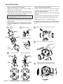
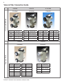
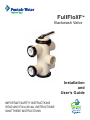
FullFloXF™ Backwash Valve Installation and User’s Guide IMPORTANT SAFETY INSTRUCTIONS READ AND FOLLOW ALL INSTRUCTIONS SAVE THESE INSTRUCTIONS i Customer Service / Technical Support If you have questions about ordering Pentair Water Pool and Spa (“Pentair”) replacement parts, and pool products, please use the following contact information: Customer Service (8 A.M. to 5 P.M. — Eastern and Pacific Times) Technical Support Phone: (800) 831-7133 Phone: (919) 566-8000 Sanford, North Carolina (8 A.M. to 5 P.M. ET) Fax: (800) 284-4151 Fax: (919) 566-8920 Web site Moorpark, California (8 A.M. to 5 P.M. PT) visit www.pentairpool.com or www.staritepool.com to find information about Pentair products. Phone: (805) 553-5000 (Ext. 5591) Fax: (805) 553-5515 Table of Contents General Installation Information ....................... i Important Warning and Safety Instructions ..... Installation and Operation ................................ ii Cleaning and/or Replacing O- Rings on Diverter and End Cap 3 1 Valve Reassembly 4 Maintenance ...................................................... 5 Valve Connection and Filter Position 1 Installing the Valve onto the Filter 2 Valve Care 5 Important Installation Guidelines 2 Winterizing 5 Normal Operation 2 Troubleshooting ................................................ 6 Backwashing 2 Valve Dimensions .............................................. 6 3 Replacement Parts ............................................ 7 Servicing ............................................................. Removing Diverters for Inspection or Service 3 Cleaning and/or Replacing Diverters 3 Illustrated Parts List 7 Valve Head Loss Curves 7 Valve Connections: Quick Reference Guide 8 General Installation Information The following information should be read carefully since it outlines the proper manner of care and operation for your filter system. You can expect maximum efficiency and life from your filtration system by following these instructions and taking the necessary preventative care. • Have a trained pool professional perform all pressure tests. • Do not connect the system to a high pressure or city water system. • Trapped air in the system can create a hazardous condition. BE SURE to purge all air from the system before operating or testing equipment. • DO NOT pressure test with compressed air! • • • • • • Piping must conform to local/state plumbing and sanitary codes. Support piping independently to prevent strains on filter or valve. Fittings restrict flow; for best efficiency, use the fewest possible fittings. A check valve installed ahead of the filter inlet will prevent contaminants from draining back into the pool. A check valve installed between the filter and heater will prevent hot water from backing up into the filter and deforming the internal components. All wiring, grounding and bonding of associated equipment must meet local and/or National Electrical Code standards. For information about the Virginia Graeme Baker Pool and Spa Safety Act, contact the Consumer Product Safety Commission at (301) 504-7908 or visit www.cpsc.gov. Important Note: Always turn off all power to the pool pump before installing the cover or working on any suction outlet. P/N 270505 Rev. B 4/19/12 FullFloXF™ Backwash Valve Installation and User’s Guide ii IMPORTANT WARNING AND SAFETY INSTRUCTIONS Important Notice: This guide provides installation and operation instructions for the FullFloXF™ Backwash Valve. Consult Pentair with any questions regarding this equipment. Attention Installer: This guide contains important information about the installation, operation and safe use of this product. This information should be given to the owner and/or operator of this equipment after installation or left on or near the valve. Attention User: This manual contains important information that will help you in operating and maintaining this valve. Please retain it for future reference. Before installing this product, read and follow all warning notices and instructions which are included. Failure to follow safety warnings and instructions can result in severe injury, death, or property damage. Call (800) 831-7133 for additional free copies of these instructions. Consumer Information and Safety The FullFloXF™ Backwash Valve is designed and manufactured to provide many years of safe and reliable service when installed, operated and maintained according to the information in this manual and the installation codes referred to in later sections. Throughout the manual, safety warnings and cautions are identified by the “ ” symbol. Be sure to read and comply with all of the warnings and cautions. SERIOUS BODILY INJURY OR DEATH CAN RESULT IF THIS VALVE IS NOT INSTALLED AND USED CORRECTLY. INSTALLERS, POOL OPERATORS AND POOL OWNERS MUST READ THESE WARNINGS AND ALL INSTRUCTIONS BEFORE USING THIS VALVE. This valve is intended for use in swimming pool applications. Most states and local codes regulate the construction, installation, and operation of public pools and spas, and the construction of residential pools and spas. It is important to comply with these codes, many of which directly regulate the installation and use of this product. Consult your local building and health codes for more information. To reduce risk of injury, do not permit children to use or operate this valve. When setting up pool turnovers or flow rates the operator must consider local codes governing turnovers as well as disinfectant feed ratios. DO NOT increase pump size; this will increase the flow rate through the circulating system and may exceed the maximum flow rate stated on the drain cover. Pumps are not a substitute for properly installed and secured pool drain covers. An ANSI/ASME A112.19.8 approved anti-entrapment drain cover must be used for each drain. Pools and spas should utilize a minimum of two drains per pump. If a drain cover becomes loose, broken or is missing, close the pool or spa immediately and shut off the pump until an approved anti-entrapment drain cover is properly installed with the manufacturer’s supplied screw. FullFloXF™ Backwash Valve Installation and User’s Guide FILTER OPERATES UNDER HIGH PRESSURE. When any part of the circulating system, (e.g., clamp, pump, filter, valve(s), etc.), is serviced, air can enter the system and become pressurized. Pressurized air can cause the lid to separate which can result in severe injury, death, or property damage. To avoid this potential hazard, follow these instructions: 1. Before repositioning valve(s) and before beginning the assembly, disassembly, or adjustment of the clamp or any other service of the circulating system: (A) Turn the pump OFF and shut OFF any automatic controls to ensure the system is NOT inadvertently started during the servicing; (B) open the manual air relief valve; (C) stand clear of the filter; (D) wait until all pressure is relieved. 2. Whenever installing the filter clamp FOLLOW THE FILTER CLAMP INSTALLATION INSTRUCTIONS EXACTLY. 3. Once service on the circulating system is complete FOLLOW SYSTEM RESTART INSTRUCTIONS EXACTLY. 4. Maintain circulation system properly. Replace worn or damaged parts immediately, (e.g., clamp, pressure gauge, valve(s), o-rings, etc). 5. Be sure that the filter is properly mounted and positioned according to instructions provided. The valve must be installed by a qualified pool serviceman in accordance with the National Electrical Code and all applicable local codes and ordinances. Always disconnect power to the pool equipment at the circuit breaker before servicing any of the equipment. Be sure that the disconnected circuit is locked out or properly tagged so that it cannot be switched on while you are working on the pool equipment. Failure to do so could result in serious injury or death to serviceman, pool users or others due to electric shock. Position the filter and the air relief valve to safely direct water drainage and purged air or water. Water discharged from an improperly positioned filter or valve can create an electrical hazard that can cause severe personal injury as well as damage property. A pool or spa pump must be installed by a qualified pool and spa service professional in accordance with the National Electrical Code and all applicable local codes and ordinances. Improper installation may create an electrical hazard which could result in death or serious injury to pool users, installers, or others due to electrical shock, and may also cause damage to property. For filters intended for use in other than single-family dwellings, a clearly labeled emergency switch shall be provided as part of the installation. The switch shall be readily accessible to the occupants and shall be installed at least 5 feet (1.52 m) away, adjacent to, and within sight of, the valve. Water temperature in excess of 100°F (37.7°C) may be hazardous to your health. Prolonged immersion in hot water may induce hyperthermia. Hyperthermia occurs when the internal temperature of the body reaches several degrees above normal body temperature of 98.6°F (37°). Effects of hyperthermia include: (1) Unawareness of impending danger. (2) Failure to perceive heat. (3) Failure to recognize the need to leave the spa. (4) Physical inability to exit the spa. (5) Fetal damage in pregnant women. (6) Unconsciousness resulting in danger of drowning. The use of alcohol, drugs, or medication can greatly increase the risk of fatal hyperthermia in hot tubs and spas. 1 Installation and Operation Do not operate this unit above the maximum operating pressure of the valve or the filter. Operating your system above maximum recommended pressure may cause your filter or valve to separate and result in severe injury, death, and property damage. Never connect the filter and valve unit to a pump, which can generate a pressure that exceeds the operating pressure of the filter or valve. Chemical fumes and/or spills can severely damage the structural components of the filter or valve. Structurally weakened components can cause the valve or the filter lid to separate and result in severe bodily injury, death, and property damage. If the valve is hard to rotate, shut the pump off before rotating between positions. Do not use excessive force. If shutting off the pump does not ease the rotation, service the valve as described in this manual. There may be foreign objects obstructing one of the internal components. Be careful not to allow any glue to get into the central bore of the valve body, as this can damage the internal components. Do not use excess amounts of glue. Valve Connection and Filter Position 1. The images below show the valve orientations that correspond to filter inlet position (depends if the inlet is on the top or the bottom). Valve Position: Filter Inlet on BOTTOM 2. Align the valve with the filter tank according to the part numbers listed below. Push the valve into the ports and turn the bulkhead nuts snugly on the tank fittings. Hand tighten the nuts - no tools are required. Valve Part Numbers: Filter Inlet on BOTTOM To Pool P/N 263081 Pentair P/N 262508 Sta-Rite P/N 262512 FullFloXF P/N 262511 No Fittings From Pump Filter Inlet Valve Position: Filter Inlet on TOP Valve Part Numbers: Filter Inlet on TOP Filter Inlet From Pump P/N 263080 Pentair P/N 262507 Sta-Rite To Pool P/N 262509 No Fittings FullFloXF™ Backwash Valve Installation and User’s Guide 2 Installing the Valve onto the Filter Important Installation Guidelines 1. Turn off all power to the system. 1. Piping size: 2-1/2” or 3” CPVC/PVC pipe fittings can be plumbed directly into valve port socket. 3” plumbing requires a 3” coupling or 90° elbow slipped over the valve port spigot. (Also can be used with any size PVC plumbing with appropriate adapters). Note: Be sure that no glue enters inside of valve body past the ports. The recommended pipe glue to use is WELD-ON® 724 CPVC, GRAY or glue types such as WELD-ON® 790™ MULTI-PURPOSE SOLVENT CEMENT. For retrofit installations only, follow steps a-d. For new installations, proceed to Step 2. a. Open the pressure relief valve on the top of the filter. Stand clear while air is released from the system. b. If the filter is below pool level, close the suction and return line valves to isolate the filtration system. c. Remove the drain plug from the filter to drain the water from the filter. d. Remove existing valve from the filter. 2. Place O-rings on the face of the union fittings, where the face of the backwash valve union will connect to the filter bulkheads. Be sure O-Ring is seated into the groove of each union piece. 1 Union Nut Adapter 2. Support piping in such a way that strain is not placed on the valve or filter. 3. The maximum operating pressure of this valve is 50 psi. The filter unit also has a maximum operating pressure listed on the filter nameplate. Normal Operation 1. Be sure the valve handle is pointing towards FILTER. 2. Turn on the filter pump. Check the system for normal water flow. 2 Backwashing 1. Turn off all system pump(s). 2. Release all pressure from the system at the main filter. 3. Turn the valve handle to the BACKWASH position. 4. Turn on the system pump(s) and run the system until the water runs clean. 5. Turn off all system pump(s). 6. Return the valve handle to the FILTER position. 7. Turn on system pump(s) and check for normal water flow. Retainer Ring 3 4 XF Union Installation Union Nut 3-Way Valve O-Ring Spa Pool OFF Filter Pump Sta-Rite Union Installation Pump Outlet (Pool Return) 3. Holding the valve upright, place onto the filter bulkheads. Tighten both union nuts to secure the valve on the filter. Filter 4. Plumb the discharge of the pump into the valve inlet labeled FILTER INLET. 5. Plumb the valve outlet labeled FILTER OUTLET to the heater or pool return lines. Pump Inlet (From Pump) 6. Plumb the WASTE ports as needed. Let the system dry for 24 hours. Backwash Valve To Waste Normal Operation FullFloXF™ Backwash Valve Installation and User’s Guide 3 Servicing Incorrect assembly of the internal components may cause your filter to dead head and could cause severe bodily and/or property damage. Use only use silicone based lubricants on the valve, other types of lubricant may damage the plastic or rubber components. Removing Diverters for Inspection or Service 1. Shut off the pump and open the manual relief valve on the filter to relieve all internal pressure. 2. If the filter is below the pool water level, close the suction and the return line valves to isolate the filtration equipment. 3. Drain the filter by moving the valve handle to the backwash position and removing the filter drain plug. 4. Remove the handle by firmly pulling the handle straight up. 5. Pull the tabs (if needed, insert two flat head screwdrivers behind the tabs) and rotate the top counter-clockwise to unlock. Remove the end cap. 6. Slowly pull out the diverter assembly. Note which diverter is on the top before reassembling. Removing the Handle Cleaning and/or Replacing the Diverters 1. DOW CORNING® 111 LUBRICANT or similar lubricant is recommended as a seal lubricant. Note: This lubricant is formulated to seal surfaces and extends the lubrication period. Many other lubricants are broken down quickly by pool water and have a short lubricating life. 2. Inspect all seals for nicks and cuts. Replace diverter if damaged. 3. Inspect the bore of the valve especially around the ports. Deep scratches and cuts in this area may cause leaks from the waste port. Replace valve if damaged. Removing the End Cap 4. Using a clean cloth, thoroughly clean all seals and the bore of the valve. End Cap 5. Apply liberal amounts of DOW CORNING® 111 LUBRICANT or similar lubricant to the surface of all seals. End Cap O-Ring Cleaning and/or Replacing the O-Rings on Diverter and End Cap Diverter O-Ring 1. Without over-stretching, remove and clean O-rings with a clean cloth. 2. Clean the O-ring grooves with a clean cloth. 3. Apply liberal amounts of DOW CORNING® 111 LUBRICANT or similar seal lubricant to the O-rings. 4. Replace the O-rings in their grooves. Cleaning the O-Ring FullFloXF™ Backwash Valve Installation and User’s Guide 4 Valve Reassembly 1. Insert the outlet diverter into the center diverter. Align the three keys as shown below. 2. Insert the inlet diverter into the center diverter. Align the fins as shown below. 3. Insert spring and seal into the correct key of the center diverter. Follow either configuration A or B below, based on the model part number: A. Inlet on TOP: P/N 263080, 262507, 262509 B. Inlet on BOTTOM: P/N 263081, 262508, 262511, 262512 Note: There are two possible positions for the seal, the text on the center diverters states which side to place the seal. 4. Lubricate all sealing surfaces on the seal and diverters with DOW CORNING® 111 LUBRICANT or similar lubricant. 1 & 3 2 5. Slide the diverter assembly into the body of the valve. Follow configuration A or B below. 6. Align the arrow and notch on the end cap and body. 7. Press the cap on and turn clockwise until the side snaps are locked into place. Note: End caps only fit one way and must be locked into place. 8. Partially install the handle and rotate until the arrow on the handle is between the two arrows on end cap. 9. Press the handle until it is locked into place. 10. Inspect the valve. When valve is in the filter position, the waste port should be blocked off with the waste seal. 6 A. Inlet on TOP Align the notch on the end cap with the arrow. Waste Seal Inlet Diverter Spring Center Diverter Fins to align B. Inlet on BOTTOM Spring 7 Press the cap down and turn clockwise. 8 Install handle. Rotate until arrow on handle is between the ‘Filter’ and ‘Backwash’ arrows. Keys to align Outlet Diverter Waste Seal A. Inlet on TOP 5 B. Inlet on BOTTOM Outlet Diverter Inlet Diverter Inlet Diverter Outlet Diverter FIL T H ER BACKW AS P/N 263081, FullFloXF™ Backwash Valve262508, Installation P/N and263080, User’s262507, Guide 262511, 262512 (Inlet on BOTTOM) 262509 (Inlet on TOP) 5 Maintenance Continuing to operate a valve with damaged components could result in sudden failure of valve structural components, which could possibly cause flooding or serious personal injury due to a sudden release of filter system pressure. Inspect and service your valve regularly as described in this section. To extend valve life, periodically inspect shaft seals and valve bore for dirt and clean as described in the Servicing section on page 3. To extend seal life, remove diverters and lubricate periodically. Valve Care Proper care and valve maintenance will add many years of service to the pool. The service life of the valve is determined by factors such as dirt, heat, weather exposure, etc. Follow the suggestions described in this section to maximize the life of the valve. 1. Dirt Dirt particles may accumulate on the seals and can scratch the valve body during normal filter operation and backwashing. These scratches can accumulate on the bore which cannot be repaired. Replace valve or diverters when the seals can no longer function properly from dirt accumulation 2. Heat This valve is not damaged by temperatures found in correctly plumbed pool and spa installations. Heat damage can be caused by: • Improper heater installation or operation: Heaters should be located after the pool filtration equipment and must have a check valve or similar device that ensures super heated water cannot backup into the valve when the pump is switched off. • Circulation pump operating with no flow: Pumps transfer heat into the water; if there is no water flow due to a closed valve or loss of prime, water in the pump will become very hot and can damage any pool equipment inline and close to the pump. • Always be sure the system valves are open so that water is free to flow through the pool equipment. 3. Weather Exposure All materials are affected to some degree by weather exposure. Materials used in this valve are suitable for outdoor use. • • • To extend valve life, protect from weathering, especially direct sunlight. Years of outdoor exposure can cause materials to become structurally weakened. Always replace valve components that show signs of deterioration, such as cracked surfaces and/or significant discoloration. 4. Chemical Damage • • • • Maintain pool water chemistry properly. Pool chemistry is a specialized area and you should consult your pool service specialist for specific details. Always introduce chemicals into the pool after water flow passes through the pool filtration equipment. Use only silicone based lubricants. Other lubricants may damage valve components. Always install a check valve between in-line chlorinators and pool equipment to prevent chlorine gas from backing up into the pool equipment. 5. Lubrication Thick silicone grease allows O‑rings to glide easily over stationary plastic surfaces. Lubrication makes handle actuation easy and ensures seals are not damaged when passing over internal passageways in the valve. • Frequency of lubrication depends on: -- Frequency of actuation -- Water chemistry -- Water quality -- Water temperature • Inspect seals and the small shaft seal after three (3) months to be sure they are well lubricated. • Valve may be reassembled and checked again in three (3) more months. • O-rings that have been cut, nibbled out, or twisted may be signs of inadequate lubrication. Damaged O-rings must be replaced. Winterizing 1. Consult your filter operation and user’s manual for winterizing instructions. 2. If possible, remove, clean and lubricate the O-rings and diverters as described on page 3. 3. Store the parts in an airtight container or sealed plastic bag that protects from light and air. 4. Store away from heat. Note: If the diverters will be left in the valve body during the winter, lubricate the valve first to be sure the diverters will actuate easily after several months without movement. FullFloXF™ Backwash Valve Installation and User’s Guide 6 Troubleshooting Problem Possible Cause Corrective Action Leak to waste. Dirt on seal, damaged seal. Service valve (see servicing instructions on page 3). Scratched valve bore. Replace valve. Heat damage to valve bore (oversized or out of round). Replace valve. Dirt on small diverter O-rings or damaged seal. Service valve (see page 3). Damaged end cap or diverter. Replace end cap or diverter. Dirt or damage to end cap O-ring. Service valve (see page 3). Sealing surface on the body damaged. Replace valve. End cap O-ring groove damaged. Replace end-cap. Seals and/or small shaft seals and/or diverters need lubrication or are damaged. Service valve (see page 3). Valve bore is badly scratched. Lubricate seals frequently. If it is still hard to actuate, replace the valve. Valve body damaged by heat. Replace valve. Foreign objects stuck between the diverters and the body. Service valve (see page 3). Leak around shaft exiting from cap. Leak between end-cap and valve body. Handle is hard to actuate. Valve Dimensions 8.1 3.4 17.4 7.5 3.5 SPIGOT FOR 3" PVC COUPLING 3.5 12.175 6.100 3.4 4.2 9.5 FullFloXF™ Backwash Valve Installation and User’s Guide 7 Replacement Parts Item No. Part No. Description 1 270187z Handle 2 270190z End Cap, 2 required 3 270197z O-Ring #2-244 Buna (two required) 4 192039 O-Ring #2-116 Buna (two required) 5 270199z Outlet Diverter 6 270200z Inlet Diverter 7 274426z Pentair Union Assembly 8 274416z Center Diverter 9 274417z Waste Seal 10 274421z Waste Seal Spring 11 274494 O-Ring #2-332 Buna 12 261067z Sta-Rite Union Assembly 13 U9-362 O-Ring #2-231 Buna 14 411101z XF Union Kit 13 2 5 6 Rebuild Kit: Items 3 (Qty. 2), 4 (Qty. 2), 5, 7, 10 - 270513z O-Ring Kit: Items 3 (Qty. 2), 4 (Qty. 2) 0 0.59 2.26 5.32 9.49 13.74 Pressure PSI 0 0.5428 2.0792 4.8944 8.7308 12.6408 Pressure Ft 0.0 1.3 4.8 11.3 20.1 29.2 10 9 270514z Pressure PSI 8 14 - 0 63.7 124.8 188.4 249.2 298.6 3 4 7 (Not Shown) flow (gpm) 1 12 flow (gpm) Pressure PSI 0 62.2 125.6 188.4 250.1 300.2 Valve Head Loss Curves 11 pressure Ft 0 0.12 0.4 0.84 1.41 1.89 0 0.276792 0.92264 1.937544 3.252306 4.359474 FullFloXF Valve Head Loss Curves - Filter Mode FullFloXF ValveHead Head Loss Loss Mode Curve Mode Head LossCurves Curve--Filter -Filter Filter Mode 14 35 35 70 70 25.0 30 30 60 60 25 25 50 50 20 20 6 40 40 4 15 15 30 30 10 10 20 20 20.0 8 15.0 6 10.0 4 2 2 5.0 0 0 0.0 0 0 50 50 100 100 150 150 200 Flow, GPM Flow FlowRate Rate-- GPM GPM 200 250 250 300 300 262508, 263080, 263081 262507,262507, 262508, 263080, 263081 (2” plumbing) 262509. 262511, 262512 Pressure Drop --PSI Pressure Drop -PSI PSI Pressure Drop 8 10 Head Loss,- Ft. Head Loss Ft. 10 80 80 30.0 12 Pressure Drop,- PSI Pressure Drop PSI Pressure Drop - PSI 12 FullFloXF Loss Curve HeadHead Loss Curve - -Backwash Mode FullFloXF Head Loss Curve -Backwash BackwashMode Mode 40 40 5 5 10 10 0 0 0 0 0 0 50 50 100 100 150 150 Flow Rate - GPM Flow Rate - GPM Flow Rate - GPM 200 200 Head Loss Ft. Head Loss---Ft. Ft. Head Loss 14 250 250 Backwash Head Loss Curve Backwash Head Loss Curve 262509, 262511, 262512 (3” plumbing) FullFloXF™ Backwash Valve Installation and User’s Guide 8 Filter Inlet - TOP Filter Inlet- BOTTOM Valve & Filter Connection Guide PENTAIR STA-RITE XF FILTERS P/N 263081 P/N 262508 P/N 262512 Filter P/N Pentair Filters Filter P/N Sta-Rite Filters Filter P/N XF Filters Filter P/N XF Filters 180006 FNS Plus FNSP24 S7D75 System 3 DE Filter 188626 XF Q-60 DE 188618 XF F-36 DE 180007 FNS Plus FNSP36 S8D110 System 3 DE Filter 188627 XF Q-80 DE 188619 XF F-48 DE 180008 FNS Plus FNSP48 S7S50 System 3 Sand Filter 188613 XF Q-100 DE 188620 XF F-60 DE 180009 FNS Plus FNSP60 S8S70 System 3 Sand Filter 188616 XF Q-120 DE 188621 XF F-72 DE Filter P/N PENTAIR STA-RITE P/N 263080 P/N 262507 Pentair Filters Filter P/N Pentair Filters Filter P/N Sta-Rite Filters 188592 Quad DE 60 140264 TR 60 Sand PLDE 36 System 2 Mod DE 188593 Quad DE 80 140210 TR 100 Sand PLDE48 System 2 Mod DE 188594 Quad DE 100 140243 TR 140 Sand S7MD60 System 3 Mod DE 140212 TR 60 Sand 140335 TR 100 HD S7MD72 System 3 Mod DE 140236 TR 40 Sand 140315 TR 100C Sand 140249 TR 50 Sand 140316 TR 140C Sand FullFloXF™ Backwash Valve Installation and User’s Guide SAVE THESE INSTRUCTIONS © 2012 Pentair Water Pool and Spa, Inc. All rights reserved. 1620 Hawkins Ave., Sanford, NC 27330 • (919) 566-8000 10951 West Los Angeles Ave., Moorpark, CA 93021 • (805) 553-5000 This document is subject to change without notice. FullFloXF™, Sta-Rite®, and Pentair Water Pool and Spa® are trademarks and/or registered trademarks of Pentair Water Pool and Spa, Inc. and/or its affiliated companies in the United States and/or other countries. Weld-On® is a registered trademark of IPS Corporation and Dow Corning® is a registered trademark of Dow Corning Corporation. Unless noted, names and brands of others that may be used in this document are not used to indicate an affiliation or endorsement between the proprietors of these names and brands and Pentair Water Pool and Spa, Inc. Those names and brands may be the trademarks or registered trademarks of those parties or others. *270505* P/N 270505 Rev. B 4/19/12