1
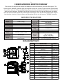
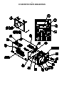
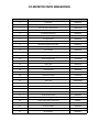
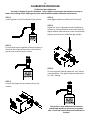
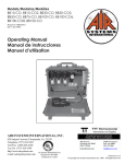
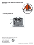
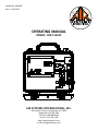
Manual No. MON006
Rev. 5 April 2013
OPERATING MANUAL
MODEL: CO91-14LAC
Air Systems International, Inc.
829 Juniper Crescent, Chesapeake, Va, 23320
Telephone (757) 424-3967
Toll Free 1-800-866-8100
Fax No. (757) 424-5348
http://www.airsystems.com
e-mail: [email protected]
2
cArBon monoXiDe monitor oVerVieW
The monitor will analyze the air sample and display the CO concentration in parts per million (ppm). The
system’s green “NORMAL” operation light will illuminate and the red “HIGH CO” light will flicker approximately
every second when the CO level is below 10ppm (5ppm Canadian). If the CO concentration level exceeds the
alarm set point, the green “NORMAL” light will turn off, the red “HIGH CO” light will illuminate, the audible
alarm will sound, and the remote alarm connections will energize. Once the CO concentration levels drop below the alarm set point, all alarm indicators will deactivate and the unit will return to “NORMAL” operation.
MONITOR SPECIFICATIONS
Size
Weight
Case
Voltage
Shielding
Fuse
Operating
Temperature
Humidity
Range
Flow
Requirement
Display
2.75”H X 6.57”L X 5.1”W
2.8 lBS. (1.27kg.)
Extruded Aluminum - anodized black
115 VAC and/or 9-16 VDC
Internal RFI/EMI filters
115 VAC/1 amp fast acting
4° to 113° Fahrenheit
(-15.5° to 45° Celcius)
10% to 90% relative humidity
50 - 100 cc/min
3 digit LCD
CO concentration
Test Circuit
Sensor Type
Accuracy
Response
Detectable
Range
Calibration
Alarm Setting
Warning
Signals
Warranty
Manually activated
Sealed electrochemical sensor for
Carbon Monoxide
+/-1% full scale
90% in 10-15 seconds
0-200 ppm CO
Manual CO zero and span adjustments
10 ppm CO (5 ppm - Canadian)
Normal operation - Green Light
High CO - Red Light
High CO - Audible Alarm
Low Battery - Amber Light
2 years from original date of purchase
REPLACEMENT PARTS
ITEM #
1
2
3
4
5
6
7
8
9
10
11
12
13
14
15
16
17
18
19
DESCRIPTION
CARBON MONOXIDE MONITOR
AUDIBLE ALARM
RED LED
CLEAR LENS
REMOTE ALARM JACK
REMOTE ALARM JACK COVER
GREEN LED
PLUG
HOSE CLAMP
AIR SAMPLE HOSE (PER FOOT)
HANSEN 3000 SERIES PLUG
AIR SAMPLE SOCKET
1/4” STREET TEE
120 VAC RECESSED PLUG
AIR SAMPLE INLET
FLOWMETER
PRESSURE GAUGE
PRESSURE REGULATOR
RELIEF VALVE
PART #
CO-91
ELLS004
MONC004
ELDS013
ELJP004
ELJP005
MONC005
MONC002
HOS056
HOS004
QDH3PL2M
QDCSL4M
BR4TS
ELJP006
QDCSL4M
WL033NS
GA1560S
WL013A
VR2125BR
3
setup/operation
Step 1)
Secure a low pressure Grade-D air source, under 150 PSI.
Step 2)
Attach sample hose to the air sample inlet located on the right side of the
case and to the air source, 125 PSI max.
Note: A sample hose is provided with two fittings so that a set up for
a standard 1/4” fitting or a retrofit for an ambient air pump can be
achieved. For an air pump set up, remove the pressure gauge and install a
street tee in to the gauge port. Screw the socket into the street tee; this is
the connection port for the monitor. Install the quick connect plug on the
sample hose and secure with the clamp provided.
See page 4.
Step 3)
Adjust the regulator pressure to a maximum reading of 20 PSI.
Step 4)
Adjust the flowmeter so the ball hovers between 50 and 100 cc/min.
Step 5)
Place the “ON/OFF/TEST” switch to the “ON” position. Allow 30 seconds
for the readout to stabilize. If a reading other than “ZERO” is displayed,
calibration of the monitor may be necessary. If the CO concentration level
exceeds the alarm set point, the green “NORMAL” light will turn off, the
red “HIGH CO” light will illuminate, the audible alarm will sound, and the
remote alarm connections will energize. Once the CO concentration level
drops below the alarm set point, all alarm indicators will deactivate and
the unit will return to “NORMAL” operation.
AIR SAMPLE INLET
LOCATED ON RIGHT
SIDE OF CASE
1/4” INDUSTRIAL
INTERCHANGE PLUG
RETRO-FIT KIT FOR
AMBIENT AIR PUMP
4
UNIVERSAL AIR PUMP ADAPTER KIT FOR CO91-14LAC
STEP 1
Remove existing gauge from bushing.
STEP 2
Install street tee in bushing. Install colder socket and
gauge in street tee as shown.
STEP 3
Slide hose clamp over end of hose. Slide colder plug
onto hose and crimp hose clamp over colder plug.
ADAPTER HOSE FROM L.P. AIR SOURCE TO CO91-14LAC
STEP 1
Slide hose clamp over end of hose. Slide
1/2” plug onto hose and crimp hose clamp over hose
barb.
STEP 2
Install 1/4” plug on Breather BoxTM or other air source
to be tested. Maximum pressure 125 PSI.
cAUtion: Always depressurize the
5 system before performing service.
Filter Housing/Bowls: Periodic cleaning of the polycarbonate bowls may become necessary. Remove the auto
drains and clean the bowls with a mild soapy solution. The auto drains may also be cleaned with a mild soapy
solution at this time. Dry and reinstall into the filter housing.
Filter Change: The filtration system consists of filter change indicators which will gradually change from green to
orange when filter life is spent.
Note: Air must be flowing through the filters before the filter change indicators will function.
With system pressurized, close inlet ond outlet ball valves. Release the filter trio pressure by pressing the manual
SYSTEM
MAINTENANCE
drain assembly to the side. Remove the
bowl assemblies
by releasing the lock ring.
Calibration: Monitor calibration should be done monthly or whenever the reading may be questionable. A calibration date sticker should be affixed for future reference. To obtain an accurate calibration, we recommend the
use of Air Systems calibration kits.
Part Number:
BBK-10
Canadian calibration kit for CO monitor; 10ppm CO, zero air, regulator and case - 17 liter size.
BBK-20
Calibration kit for CO monitor; 20ppm CO, zero air, regulator and case - 17 liter size.
BBK-20103 Calibration kit for CO monitor; 20ppm CO, zero air, regulator and case - 103 liter size.
DECAL085 Calibration decal, sold in sheet of 14.
To assure sensor accuracy, calibration of monitor is required. If you cannot obtain an accurate calibration, sensor
replacement may be necessary. Consult Repair Service Department before ordering.
Part Number:
CO-91NS Replacement CO sensor
monitor BAttery rePlAcement
These batteries provide the required continuous bias voltage to the CO sensor and power the monitor in the
event of AC power loss. If AC and DC power are removed for a period of 2 hours or more, a 1 hour restabilization period is required on the sensor as eratic readings may occur.
Battery Replacement: Replace 9 volt batteries when the amber “Low Battery” light illuminates. If the monitor
is not used for 90 days, check the 9 volt batteries and replace if necessary.
6
CO MONITOR PARTS BREAKDOWN
7
CO MONITOR PARTS BREAKDOWN
ITEM #
DESCRIPTION
PART #
1
LCD Display
MONC703
2
Span Potentiometer
MONC702A
3
Alarm Set Point Potentiometer
MONC702A
4
Zero Potentiometer
MONC702
5
Air Sample Inlet Socket
MONC001
6
Air Sample Plug
MONC002
7
Air Exhaust Port
MONC003
8
On/Off/Test Switch
MONC007
9
Recessed Plug With Fuse Holder
MONC020
10
1 Amp Fast Acting Fuse, 5 X 20Mm
ELF001
11
15 Pin Socket
MONC520
12
Faceplate/Endplate Screw
MONC023
13
Main Circuit Board Assembly
CO-91PCB
14
Power Supply Board
CO-91PSB
15
Sensor Connector (Soldered To PCB)
MONC509
16
Battery Box
MONC006
17
9 Volt Battery
ELB9V
18
Calibration Tool
MONC028
19
End Plate
CO-91BEP
20
Aluminum Housing
CO-91HOU
21
Led Socket
MONC009LA
22
Yellow Led
MONC008NS
23
Led Socket And Yellow Led
CO-91LED
24
PPM/Serial No. Sticker
MONC031
25
Battery Box Connector (Soldered To PCB)
MONC516
26
Led Connector (Soldered To PCB)
MONC511
27
12 VDC Power Socket
MONC522
28
12 Volt Power Plug (Optional)
ELJP018
29
12 Volt Cable (Order By The Foot)
ELCB035
30
CO Sensor
CO-91NS
31
CO Sensor Holder
MONC810
32
CO Sensor Electrical Leads
CO-91SL
33
90° Hose Barb
MONC811
8
SenSor rePlAcement
Replacement sensors are shipped with a metal spring installed between the electrodes. Do not remove the
clip until the sensor is to be installed into the monitor.
SteP 1)
SteP 2)
Disconnect all external connections. Remove the four screws from the
Remove CO monitor from the unit. monitor’s left endplate.
SteP 3)
Remove endplate to gain access to
the sensor cup.
UNUSED
CONTROL
(BLACK)
REFERENCE
(BLUE)
SENSING
(RED)
SteP 4)
Remove sensor from sensor cup and remove leads. Take the
new sensor and remove the metal spring. Reattach leads to
the proper colored terminals on the new sensor. Install new
sensor into sensor cup.
SteP 5)
Reassemble monitor and reinstall in
unit. Connect all cables and air sample hose. Allow monitor to stabilize
30 minutes to 1 hour and recalibrate.
9
cAliBrAtion ProceDUre
Do not use inert gases to zero the monitor. This will cause premature failure of the sensor.
CO Monitor Zero Adjustment
To zero the monitor, follow the steps below. Zero calibration gas should be used to properly “zero” the
monitor and assure that a valid calibration is achieved. If zero adjustment cannot be made as indicated, sensor replacement may be necessary. After each monitor adjustment outlined in the steps, allow time for the
changes to stabilize.
SteP 1)
Place the “ON/OFF/TEST” switch in the “ON” position.
SteP 6)
Turn the knob on the regulator counterclockwise to
allow the flow of gas thru the hose. Verify flow of
gas thru the hose via touch or sound.
SteP 2)
Allow 30 seconds for the readout to stabilize. The
green indicator will illuminate.
SteP 3)
Hold the “ON/OFF/TEST” switch in the “TEST” position. The following will occur:
Audible alarm will sound
Green LED will flash
Amber Low Battery indicator on monitor will
illuminate
Red LED will be on
This test ensures the circuitry is operable and continuity to the sensor is proper. Release the switch.
SteP 4)
Remove the air sample inlet tube.
SteP 7)
Attach the clear tubing with the male plug to the air
sample inlet on the monitor.
SteP 8)
Allow digital readout to stabilize approximately 1530 seconds.
SteP 9)
Adjust the “zero” adjustment screw (clockwise to
increase or counterclockwise to decrease) until a
reading of “00” is obtained.
SteP 5)
Install regulator on the zero air cylinder reference
gas.
SteP 10)
Turn the regulator off and disconnect the regulatorfrom the zero gas cylinder.
10
cAliBrAtion ProceDUre
CO Monitor Span Adjustment
Use only 10-20ppm CO gas for calibration. Using a higher concentration may decrease accuracy at
lower scale readings. Note: 10ppm gas must be used to satisfy Canadian calibration requirements.
SteP 1)
Install regulator on the CO calibration gas cylinder.
SteP 4)
Allow digital readout to stabilize 15-30 seconds.
SteP 5)
Adjust the “span” adjustment screw (clockwise to
increase or counterclockwise to decrease) until the
digital readout reads the same as the concentration
(ppm) as printed on the calibration gas cylinder.
SteP 2)
Turn the knob on the regulator counterclockwise to
allow the flow of gas thru the hose. Verify flow of
gas thru the hose via touch or sound.
SteP 6)
Turn the regulator off and repeat the “zero” adjustment procedure. The digital readout should return
to a “00” reading.
SteP 3)
Connect the plug to the air sample inlet on the
monitor.
The monitor is now calibrated and should be
recalibrated monthly or if accuracy is questionable. Check local requirements and recalibrate as
required.
11
WArrAnty DiSclAimer
Air Systems’ manufactured equipment is warranted to the original user against defects in workmanship or materials under normal use for one year from the date of purchase. Any part which is determined by Air Systems
to be defective in material or workmanship will be, as the exclusive remedy, repaired or replaced at Air Systems’ option. This warranty does not apply to electrical systems or electronic components. Electrical parts are
warranted, to the original user, for 90 days from the date of sale. During the warranty period, electrical components will be repaired or replaced at Air Systems’ option.
no otHer WArrAnty, eXPreSSeD or imPlieD, AS to DeScriPtion, QUAlity, mercHAntABility, FitneSS
For A PArticUlAr PUrPoSe, or Any otHer mAtter iS GiVen By Air SyStemS in connection HereWitH. UnDer no circUmStAnceS SHAll tHe Seller Be liABle For loSS oF ProFitS, Any otHer Direct
or inDirect coStS, eXPenSeS, loSSeS, or DAmAGeS AriSinG oUt oF DeFectS in, or FAilUre oF tHe
ProDUct or Any PArt tHereoF.
The purchaser shall be solely responsible for compliance with all applicable Federal, State and Local OSHA and/
or MSHA requirements. Although Air Systems International believes that its
products, if operated and maintained as shipped from the factory and in accordance with our “operations
manual”, conform to OSHA and/or MSHA requirements, there are no implied or expressed warranties of such
compliance extending beyond the limited warranty described herein. Product designs and specifications are
subject to change without notice. Rev. 2, 12/98
Air leaks are not covered under warranty except when they result from a defective system component, i.e. an
on/off valve or regulator or upon initial delivery due to poor workmanship. Air leaks due to poor delivery or
damage will be covered under delivery claims. Minor air leaks are part of routine service and maintenance and
are the responsibility of the customer just as are filters and oil changes.
Air SyStemS internAtionAl, inc.
829 Juniper Crescent, Chesapeake, Va, 23320
Telephone (757) 424-3967
Toll Free 1-800-866-8100
Fax No. (757) 424-5348
http://www.airsystems.com
e-mail: [email protected]
Printed in the U.S.A. ©Copyright Air Systems International, Inc. 2012 All Rights Reserved