1
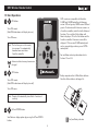
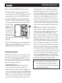
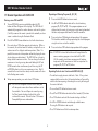
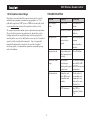
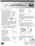
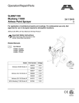
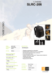
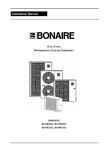
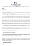
®
SLRC Remote Control
Owner’s Manual
®
OFF
ON
SLRC Wireless Remote Control
Contents
1.1System Components................................................................3
1.2Basic Operation.......................................................................4
1.3Standard Functions..................................................................5
1.4Hidden Functions.....................................................................5
1.5Installation of Wireless Receiver................................................6
1.6Setting Security Codes.............................................................7
1.7Remote Operation with SLRC-HH.............................................8
1.8Information About Range.........................................................9
1.9Firmware Compatibility..........................................................10
1.10 FCC Notice..........................................................................10
®
Residential/Light Commercial
Remote Control for all SmartLine Controllers; SL800, SL1600,
SL1620, SL1624 and SL4800
Introduction
The SmartLine Remote Control (SLRC) system saves time and
energy. For starters, SLRC eliminates walking back and forth to
the controller to start and stop manual operation. It also provides
for a remote start of any watering program in the controller and
allows for remote activation of the patented SmartLine Valve Locator
feature. SLRC saves time and extra manpower for maintenance
and repair work, simplifies winterization, and allows for quick valve
location.
SLRC provides two connection modes for ultimate flexibility. A
numeric contractor code can be set in the SmartLine controller
(01-99), allowing a single remote to operate any number of units by
simply setting the same code in the SLRC-HH handheld remote. A
second option is to “Join” the SLRC-HH handheld remote to a single
controller. This mode is typically for property owners who will only
use the remote on a single SmartLine controller.
SLRC-HH handheld remote features an LCD display with large,
easily visible digits. Four easy to use keys control all functions. Two
AAA batteries power the handheld remote. The remote turns itself
off after two minutes of inactivity to save battery life.
Congratulations! Your life just got easier.
SLRC Wireless Remote Control
®
1.1 System Components
Available
in 2011
®
®
®
SLRC-ADAPTER
OFF
ON
SLRC-HH
Handheld
Remote
SLRC-ADAPTER
SLHUB-RF
SLRC-CLIP
Receiver with 24 inch
RJ11 Pigtail
SmartLine ® communication
hub (wireless model)
Belt Holster for SLRC-HH
Available
in 2011
®
®
®
Available
in 2011
SLRC-ADAPTER
OFF
ON
SLRC-KIT-HUB
Contains both the SLRC-HH
and the SLHUB-RF
OFF
ON
SLRC-KIT-ADP
Contains both the SLRC-HH
and the SLRC-ADAPTER
SLRC-LINK
25 foot extension cable with
outdoor RJ11 connection port
SLRC Wireless Remote Control
®
1.2 Basic Operations
1
ON button:
SLRC remotes are compatible with SmartLine
SL1600 and SL4800 controllers with firmware
version 3.05 and greater; SL800 version 2.00 and
greater. To determine which firmware version is in
a SmartLine controller, rotate the dial to Advanced
Functions. Press an Adjust Value button until
About is displayed. Press the Next button and the
SmartLine controller’s firmware version will be
displayed. Older version SL1600 control panels
can be upgraded by purchasing a new SLCPSA
control panel.
®
Turns ON remote.
(Hold ON button down until display turns on.)
Turns ON zones.
Note: The first time you use the remote,
turn on zone 1 to automatically
download zone count from
SmartLine controller.
OFF
ON
For installation and setup information refer to
Sections 1.5 and 1.6.
Antenna indicates two-way transmission
of signal.
2
OFF button:
Battery compartment for 2 AAA alkaline batteries.
Substitute Lithium batteries for longer life.
Turns OFF remote.
(Hold OFF button down until display turns off.)
Turns OFF zones.
Note: Remote will automatically turn off after 2 minutes of
inactivity.
3
UP and DOWN button:
Scroll between display options by pressing the UP and DOWN
buttons.
(Lo) Low Battery indicator.
SLRC Wireless Remote Control
®
1.3 Standard Functions
1
2
(1 to 48) Indicates zone number. Use UP and
DOWN buttons to select zone. Press ON to start
zone. Zones will run for the user defined maximum
run time set in the remote (range 1-90 min, default
2 min). Refer to section 1.4 for instructions on
setting maximum run times. Press OFF to stop zone
before the maximum run time has expired.
2
(PA, PB, PC, PD) Operates all zones assigned to the
selected program for the time set in the Smartline
controller. Use the UP and DOWN buttons to
select desired program. Press ON to start. Once a
program is activated, it will complete its cycle and
turn off automatically. Press OFF to stop program.
3
(LC) Valve Locator function will “chatter” valve
solenoids for quick field locating (Note: Water
supply must be turned off for Valve Locator
operation). Press UP and DOWN buttons to select
Valve Locator (LC). Press ON button to begin
pinging zone 1. Use UP and Down buttons to index
to desired zone. Press OFF button to stop.
Note: The hourglass ICON is displayed on the
display while setting the maximum run
time.
3
4
1.4 Hidden Functions
(J) Joins SLRC-HH remote control to a single
SmartLine controller with SLHUB-RF communication
hub. Refer to section 1.6 in this manual.
Note: In SLRC-KIT-ADP and SLRC-KIT-HUB kits,
remote is pre-joined to receiver.
Press UP and DOWN buttons simultaneously to
access hidden functions.
Note: After 5 seconds of no activity, Hidden
Functions will close, the changes will
be saved and the remote will return to
Standard Functions.
(Cd) Contractor Code allows for remote access to
SmartLine controller. Valid codes are 01–99. After
accessing hidden functions, press ON button to
display code (Cd). Use UP or DOWN buttons and
scroll to select desired code. Once selected, wait 5
seconds for your contractor code to be stored.
Select identical code on SmartLine controller:
Rotate the dial to Advanced Functions. Press Adjust
Value button until WIRELESS is displayed. Press
Next button to display INSTALL and press Adjust
Value button to display SET CODE. Press Next
button and use the Adjust Value buttons to set
desired code.
Note: The Valve Locator function will override
rain and freeze sensor shutdown.
1
(1 to 90) Sets maximum run time when remotely
operating zones. Default setting is 2 minutes. Once
selected, wait 5 seconds for your maximum run
time to be stored.
SLRC Wireless Remote Control
®
1.5 Installation of Wireless Receiver
Option 2: Installing the SLRC-LINK
Wireless remote communication may be accomplished using either the
SLHUB-RF or the SLRC-ADAPTER. If an existing SmartLine installation
already has the SLW15 wireless weather station in place, you may
proceed to the next section, 1.6 Setting the Security Code.
• The SLRC-LINK may be used in lieu of the SLHUB-RF installation. The SLRC-LINK has a 25’, phone cable for outdoor connection to
the SLRC-ADAPTER. The SLRC-LINK provides remote access for
the servicing contractor or the SLRC-ADAPTER may be permanently
mounted outside to allow remote wireless communication for
SmartLine Controllers installed in a basement or any other nonaccessible location. Note: The SLRC-ADAPTER housing is water
resistant, but it should be mounted in a well protected area at a
height safe from ground flooding and direct spray from sprinklers. Option 1: Installing the SLHUB-RF • Open the control panel of the SmartLine SL1600 or the main panel
of the SL4800. The connector
location for the SLHUB-RF is
SLHUB Pin
Connector
located in the upper right-hand
corner. Carefully insert the
SLHUB-RF into the connector
1
2
terminal. The SLHUB-RF antenna
should be hanging down inside
3
the controller. Use the provided
machine screw to secure the
4
SLHUB-RF to the controller
housing.
• The SLRC-LINK cable is designed to minimize the possible effects
of electrical noise. Splicing or extending the cable may result in
remote malfunction.
FUSE
• Route the SLRC-LINK cable from the
outdoors to the controller. The cable
can be routed in the conduit with the
valve wiring for convenience or it may
be placed separately. When routing
with the valve wiring, insert a tee and
a ¾” slip elbow in the valve wiring
conduit. The elbow opening should be a
minimum of 1-foot above ground level. HOT POST
P/MV
COM
COM
SEN
SEN
AUX PWR
AUX PWR
• On the SL800, the SLHUB-RF
is installed in the back of the
housing before the controller is
mounted. Remove and discard
the compartment cover on the
back of the controller. Install the
SLHUB-RF as described above. The antenna will hang down
beneath the controller.
• Insert the RJ11 into the tee and route to the controller location.
• Insert the ¾” slip SLRC-LINK cap
into the tee. The cap will protect
the RJ11 port in the cap, but it is
not waterproof.
• Route the cable into the controller
either through the valve wiring
conduit or a separate knockout.
• Connect to RJ11 port on
SmartLine.
SLHUB
Compartment
SL4800 Controller
SLHUB Pin
Connector
FUSE
RJ11
Connectors
1
2
HOT POST
P/MV
COM
COM
SEN
SEN
AUX PWR
AUX PWR
3
4
SLRC Wireless Remote Control
®
Option 3: Installing the SLRC-ADAPTER directly to the SmartLine
the dial back to RUN. Turn on the SLRC-HH remote by holding
down the ON button until a zone number is displayed. Press and
hold the UP and DOWN buttons simultaneously until the maximum
run time appears (hourglass icon). Press the ON button one time
to display CD. Use the UP or DOWN button to select the same
code entered in the SmartLine controller.. Wait 3-5 seconds until
the remote changes to the flashing zone number. As soon as you
activate a zone with the remote, the zone count will be downloaded
from the SmartLine controller indicated by the flashing tower icon.
• If the SmartLine controller location is an existing system with a
wired SLW weather station, the SLRC-ADAPTER may be used for the
remote operation in lieu of the standard SLHUB-RF installation. • Mount the SLRC-ADAPTER in a convenient wall location beside
the controller using the two provided mounting screws. Make sure
the location chosen allows for routing the 2-foot cable to the RJ11
port in the SmartLine
controller. The SLRCADAPTER cable may
be extended using the
SLRC-LINK. Do not
splice or extend the
cable beyond the cable
length supplied with the
SLRC-LINK.
RUN MANUAL PROGRAM
®
PGM
• JOIN (J) function marries SLRC-HH remote control to a single
SmartLine controller. To JOIN the remote to your SmartLine
controller, rotate the controller dial to Advanced Functions. Using
the Adjust Value buttons, find the WIRELESS option and press
Next. The SmartLine Controller screen will flash the word INSTALL. Holding the SLRC-HH in front of the controller, press and hold the
ON button until a zone number is displayed. Then press and hold
down the UP and DOWN buttons simultaneously until a number
appears in the display with an hourglass icon. Press ON button
twice to select J in the display. Press UP button to join the Remote
to the SmartLine controller. A flashing tower icon will be displayed
on the remote when a successful marriage has occurred. In some
cases, it may take a few attempts to Join successfully. Note: As soon
as the SLRC-HH is joined to a SmartLine controller, the number of
zones will be downloaded to the remote. The Valve Locator (LC)
and manual program (PA, PB, PC, PD) features will not be available
on the remote until it is joined to the SmartLine controller.
NEXT
®
ADJUST VALUE
S LR C-A DA PTE R
BACK
MODE
AUTO ADJUST
STANDARD
ACTIVE
BYPASS
SENSOR
• Route the RJ11 cable through any access hole on the bottom of the
controller for SL1600 or SL4800 installation. The RJ11 port on the
SL800 is located on the left exterior of the housing. 1.6 Setting Security Codes
Your SLRC remote system features security code capabilities to insure
your irrigation system cannot be operated unintentionally. Note: If
you purchased the SLRC-KIT-HUB or SLRC-KIT-ADP, your remote and
receiver are pre-joined at the factory with an exclusive security code. Skip Section 1.6 and proceed to Section 1.7.
Note: When installing the remote using either Contractor Code
or the Join function, the tower icon will flash indicating a
successful install. The tower icon will flash for approximately
5 seconds and then become static.
• CONTRACTOR CODE SET (Cd) allows the contractor to set
a unique code for access to the SmartLine controller. To set
Contractor Code, rotate the SmartLine Controller dial to Advanced
Functions. Using the Adjust Value buttons, find the WIRELESS option
and press Next. The SmartLine controller screen will flash the word
INSTALL. Press one of the Adjust Value buttons to display SET CODE
and press Next. Select the Code number you want to use. Rotate
SLRC Wireless Remote Control
®
1.7 Remote Operation with SLRC-HH
Operating a Watering Program (A, B, C, D)
Turning a zone ON and OFF
1
Press and hold ON button to turn on remote.
1
Turn on SLRC-HH by pressing and holding down the ON
button until Zone # appears in the display. The SLRC-HH will
automatically recognize the number of zones active on the system
(1 to 48) as soon as the remote is joined to the controller, or when
a zone is activated using the Contractor Code.
2
Use UP or DOWN button to rotate to the selected watering
program (PA, PB, PC or PD). If the program options are not
displayed on the remote, try turning on a single zone to download
the zone and program data from the SmartLine controller.
3
2
Press UP or DOWN arrow button to select to the desired zone.
3
Press and release ON button again to start watering. Within a
few seconds, the selected zone will activate, and you will see an
antenna icon in the display to confirm operation. (Note: It is
possible for a zone to start operation without displaying the icon
due to distance or obstructions.) The SLRC-HH has a 2-minute
factory default maximum run time. You can change the default
maximum run time by pressing down and holding the UP and
DOWN arrow buttons simultaneously and then using the UP
or DOWN button to select a new maximum run time. Wait 5
seconds for the new time to be stored, and the remote will return
to the flashing zone number.
Press and release ON button to start operation of the program. The SmartLine controller will begin operating the selected program
using the run times set on the controller.
4
Press and release OFF button to stop operation of the program. 4
Note: If SLRC-HH is turned off or taken out of range before the
zone or watering program is turned off with the SLRCHH, the remotely started zone or program will continue
to operate until the maximum run time has expired or the
program (PA, PB, PC or PD) finishes.
Operating Valve Locator Function with SLRC-HH (LC)
• Turn off water supply at main cutoff valve. Note: If the system is
equipped with a master valve, the Locator function will prevent the
master valve from opening, eliminating the necessity of turning off
the main cutoff valve.
To stop zone operation, press and release OFF button. Note: The SLRC-HH recognizes a rain or freeze delay and
will not operate a zone when those conditions exist at
the controller. You can still operate a zone by using
the Valve Locator function described later in this
section of the manual. Refer to Section 1.9 Firmware
Compatibility for more information.
• Press and hold ON button to turn on remote.
• Press UP or DOWN button to rotate to Valve Locator (LC) function.
• Press ON button to activate Valve Locator starting with Zone 1.
• Use UP or DOWN button to index through available zones. Pressing the ON button is not required.
• Press OFF button to end Valve Locator operation.
SLRC Wireless Remote Control
®
1.8 Information About Range
troubleshooting
Many claims are made about the range of various wireless remote
control systems (irrigation, auto alarms, garage doors, etc). The
published range for the SLRC System is 1000 feet line-of-sight, which
means no obstructions between the transmitter and the receiver.
The range of any remote control system is dependent on many factors. These include the terrain at any particular site, obstructions such as
buildings and walls, the strength of various interfering signals, the
sensitivity of the receiver, the ability of the receiver to reject “unwanted
signals,” and the strength of the transmitter. Since it is impossible
to control the obstructions, terrain at a site, and the strength of
interfering signals, it is impossible to guarantee an operating range
under all conditions.
Problem
Cause(s)
Solution(s)
SLRC display is
blank
SLRC is OFF
Hold down ON
button
Batteries are dead
Replace AAA
batteries
Obstructions
prevent return
signal
Zone may operate
anyway
Remote turns off
Sleep mode occurs
after two minutes of
inactivity
Press ON button
Remote has short
range
Obstructions
preventing or
limiting radio signal
transmission
Try different location
or install the SLRCADAPTER to improve
performance
No transmission
Controller code
set to 00 or reset
to another code
number
Check codes set
in controller and
remote to be sure
they are the same
(Section 1.6)
SLRC not joined
Join SLRC to
SmartLine (Section
1.6)
No signal icon
Move to another
location
SLRC Wireless Remote Control
®
The SLRC-HH transmitter has been designed to transmit the maximum
power allowed by the FCC for the 2.4 GHz band. The SLRC circuitry
is also designed to maintain maximum power until just before the
batteries go dead. Additionally, the SLRC-LINK phone cable provides
maximum protection from interfering signals. The SLRC System is
designed to give you simple, reliable signals for many years.
reception, which can be determined by turning the equipment On and
Off, the user is encouraged to try to correct the interference by one or
more of the following measures:
• Re-orient or relocate the receiving antenna.
• Increase the separation between the equipment and the receiver.
• Connect the equipment to an outlet on a circuit different from that
to which the receiver is connected.
1.9 Firmware Compatibility
• Consult the dealer or an experienced radio/TV technician for help.
The SLRC Remote Control System is compatible with all SmartLine
firmware with the following exceptions:
The user is cautioned that changes and modifications made to the
equipment without the approval of the manufacturer could void the
user’s authority to operate this equipment.
• SLRC will not operate with firmware versions prior to 3.05 on the
SL1600/4800, and 2.00 on the SL800. An upgrade to a SmartLine
panel with more current firmware is required.
FCC DECLARATION OF CONFORMITY
• SmartLine control panel upgrades are available for purchase - part
number SLCPSA.
TRADE NAME
MODEL NUMBER
1.10 FCC Notice
COMPLIANCE TEST REPORT NUMBER
Transmitter FCC ID OLPSLHHR24
COMPLIANCE TEST REPORT DATE
• This device may not cause harmful interference.
RESPONSIBLE PARTY
• This device must accept any interference received, including
interference that may cause undesired operation.
ADDRESS
This equipment has been tested and found to comply with the limits
for Class B digital devices, pursuant to Part 15 of the FCC Rules. These limits are designed to provide reasonable protection against
harmful interference in a residential installation. This equipment
generates, uses and can radiate radio frequency energy and if not
installed and used in accordance with the instructions, may cause
harmful interference to radio communications. However, there is no
guarantee that interference will not occur in a particular installation. If
this equipment does cause harmful interference to radio or television
TELEPHONE
10
Remote Control Device
SLRC-HH
37576RUS1
4/6/2010
Telsco Industries
3301 West Kingsley Road, Garland, TX, USA
972-278-6131
SLRC Wireless Remote Control
®
This equipment has been tested and found to comply with the limits for
Class B digital devices, pursuant to Part 15 of the FCC Rules. These
limits are designed to provide reasonable protection against harmful
interference in a residential installation. This equipment generates,
uses and can radiate radio frequency energy and if not installed
and used in accordance with the instructions, may cause harmful
interference to radio communications. However, there is no guarantee
that interference will not occur in a particular installation. If this equipment does cause harmful interference to radio or television
reception, please refer to your user’s manual for instructions on
correcting the problem.
I, the undersigned, hereby declare that the equipment specified above
conforms to the above requirements. PLACE: Garland, TX Full Name: Venkat Bangalore
DATE: May 24, 2010 Position: Engineering Manager
11
®
AD808