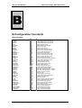
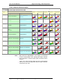
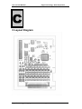
1
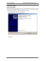
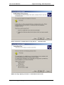
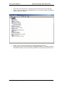
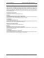
PCI 773 Series
PCI PnP Analog Board
User’s Manual
PCI773T16, PCI773R16
Eagle Technology – Cape Town, South Africa
Copyright © 2001-2002
www.eagle.co.za
PCI 773 User Manual
Eagle Technology - Data Acquisition
Analog Boards
Data Acquisition and Process Control
© Eagle Technology
31-35 Hout Street • Cape Town • South Africa
Phone +27 21 423 4943 • Fax +27 21 424 4637
Email [email protected]
Eagle Technology © Copyright 2001-2002 – www.eagle.co.za
i
PCI 773 User Manual
Eagle Technology - Data Acquisition
Copyright
All rights reserved. No part of this publication may be reproduced, stored in a retrieval system,
or transmitted, in any form or any means, electronic, mechanical, by photographing,
recording, or otherwise without prior written permission.
Copyright © Eagle Technology, South Africa
May 2002
Revision 1.5
Information furnished in this manual is believed to be accurate and reliable; however no
responsibility is assumed for its use, or any infringements of patents or other rights of third
parties, which may result from its use.
Trademarks and Logos in this manual are the property of their respective owners.
Product Warranty
Eagle Technology, South Africa, warrants its products from defect in material and
workmanship from confirmed date of purchase for a period of one year if the conditions listed
below are met. The product warranty will call the Eagle Technology Data Acquisition Device
short as ETDAQD.
•
•
•
The warranty does not apply to an ETDAQD that has been previously repaired, altered,
extended by any other company or individual outside the premises of Eagle Technology.
That a qualified person configure and install the ETDAQD, and damages caused to a
device during installation shall make the warranty void and null.
The warranty will not apply to conditions where the ETDAQD has been operated in a
manner exceeding its specifications.
Eagle Technology, South Africa, does not take responsibility or liability of consequential
damages, project delays, damaging of equipment or capital loss as a result of its products.
Eagle Technology, South Africa, holds the option and final decision to repair or replace any
ETDAQD. Proof of purchase must be supplied when requesting a repair.
Eagle Technology © Copyright 2001-2002 – www.eagle.co.za
ii
PCI 773 User Manual
Eagle Technology - Data Acquisition
TABLE OF CONTENTS
1.
INTRODUCTION
1
Features
1
Applications
1
Key Specifications
1
Software Support
1
Contact Details
2
2.
3
INSTALLATION
Package
3
Operating System Support
3
Hardware Installation
3
Software Installation
Windows 98/2000/ME
Post installation
Windows NT
4
4
7
9
Accessories
9
3.
INTERCONNECTIONS
10
External Connectors
PCI773T16 and PCI773R16
10
10
Connector Pin Assignments
PCI773
11
11
Signal Definitions
11
Analog Input Connections
12
4.
13
PROGRAMMING GUIDE
EDR Enhanced API
13
Digital Inputs/Outputs
Reading the Digital Inputs
Writing to the Digital Outputs
14
14
14
Analog Input
Reading a single voltage from a channel
15
15
Analog Input Gain Codes – PCI773
Error! Bookmark not defined.
Temperature Calculation
Eagle Technology © Copyright 2001-2002 – www.eagle.co.za
15
iii
PCI 773 User Manual
5.
CALIBRATION
Requirements
Calibrating the Analog Input Subsystem
A.
Eagle Technology - Data Acquisition
17
17
Error! Bookmark not defined.
SPECIFICATIONS
19
Analog Input Characteristics – PCI773
Input Characteristics
Conversion Characteristics
19
19
19
Digital Input Characteristics
19
Digital Input Characteristics
20
Other
20
B.
21
CONFIGURATION CONSTANTS
Query Codes
21
Error Codes
22
Analog Input Gain Codes – PCI773-T/R 16
22
ThermoCouple Type Codes
22
Color codes for thermocouples
23
C.
LAYOUT DIAGRAM
24
D.
ORDERING INFORMATION
25
Eagle Technology © Copyright 2001-2002 – www.eagle.co.za
iv
PCI 773 User Manual
Eagle Technology - Data Acquisition
Table of Tables
Table 2-1 Operating System Support ........................................................................................ 3
Table 3-1 Pinouts for PCI773 (External Connector – DB37) ................................................... 11
Table D-1 Ordering Information ............................................................................................... 25
Eagle Technology © Copyright 2001-2002 – www.eagle.co.za
v
PCI 773 User Manual
Eagle Technology - Data Acquisition
1. Introduction
The PCI773 series data acquisition boards have 32-bit PCI bus architecture. They are
available in two models, the RTD or Thermocouple version. The PCI773 contains 16 digital
input and 16 output ports and 16 differential inputs. The PCI773 has only got one range
setting witch is controlled by hardware. The range is calculated and set when manufactured.
This gain was designed to give you the optimal accuracy for the application it is to be used
for.
Features
The PCI773 does have some very unique features and are short listed below:
•
•
•
•
•
32-bit PCI bus Revision 2.2 compliant at 33MHz.
PCI Bus 3.3V or +5V slot compatible.
Fully individually programmable analog-in channels.
Fully programmable digital input channels.
Fully programmable digital output channels.
Applications
The PCI773 can be used in the following applications:
• Temperature measurements logging.
Key Specifications
•
•
•
•
Analogue resolution is 14-bit.
+/- 2.5V full-scale deviation @ 10 KHz maximum sampling rate.
16 digital inputs, 74HCT373 compatible.
16 digital outputs, 74HCT374 compatible
Software Support
The PCI773 is supported by EDR Enhanced and comes with an extensive range of examples.
The software will help you to get your hardware going very quickly. It also makes it easy to
develop complicated control applications quickly. All operating system drivers, utility and test
software are supplied on the Eagle Technology CD-Rom. The latest drivers can also be
downloaded from the Eagle Technology website. For further support information see the
Contact Details section.
Eagle Technology © Copyright 2001-2002 – www.eagle.co.za
1
PCI 773 User Manual
Eagle Technology - Data Acquisition
Contact Details
Below are the contact details of Eagle Technology.
Eagle Technology
PO Box 4376
Cape Town
8000
South Africa
Telephone +27 (021) 423 4943
Fax +27 (021) 424 4637
E-Mail [email protected]
Website http://www.eagledaq.com
Eagle Technology © Copyright 2001-2002 – www.eagle.co.za
2
PCI 773 User Manual
Eagle Technology - Data Acquisition
2. Installation
This chapter describes how to install and configure the PCI773 for the first time. Minimal
configuration is necessary; almost all settings are done through software. The PCI BIOS or
operating system will take care of all resource assignments.
Before using the board calibration of the voltage offsets is necessary.
Package
PCI773 package will contain the following:
• PCI773 PCI board
• IDC40-DB37 extender cable
• Software CD-Rom
Operating System Support
PCI773 support the following operating systems
Board Type
PCI773T16
PCI773R16
Revision
Revision 1
Revision 1
Operating Systems
Windows 2000/98/ME/XP
Windows 2000/98/ME/XP
Driver Type
WDM PnP
WDM PnP
Table 2-1 Operating System Support
Hardware Installation
This section will describe how to install your PCI board into your computer.
•
Switch off the computer and disconnect from power socket.
Failure to disconnect all power cables
can result in hazardous conditions, as
there may be dangerous voltage levels
present in externally connected
cables.
•
•
•
•
•
•
Remove the cover of the PC.
Choose any open PCI slot and insert PCI board
Insert bracket screw and ensure that the board sits firmly in the PCI socket.
Replace the cover of the PC.
Reconnect all power cables and switch the power on.
The hardware installation is now completed.
Eagle Technology © Copyright 2001-2002 – www.eagle.co.za
3
PCI 773 User Manual
Eagle Technology - Data Acquisition
Software Installation
Windows 98/2000/ME
Installing the Windows 98/2000 device driver is a very straightforward task. Because it is plug
and play Windows will auto detect the PCI board as soon as it is installed. No setup is
necessary. You simply have to supply Windows with a device driver.
Wait until Windows detects the new hardware
Select Next
Eagle Technology © Copyright 2001-2002 – www.eagle.co.za
4
PCI 773 User Manual
Eagle Technology - Data Acquisition
Select “Search for a suitable driver for my device…” and select next
Make sure only “Specify a location” is selected and select next
Eagle Technology © Copyright 2001-2002 – www.eagle.co.za
5
PCI 773 User Manual
Eagle Technology - Data Acquisition
Select the browse button and search for the PCI773.inf file on the Eagle CD-Rom.
The driver is normally located in the <CDROM>:\EDRE\DRIVERS\WDM\PCI773
directory.
Eagle Technology © Copyright 2001-2002 – www.eagle.co.za
6
PCI 773 User Manual
Eagle Technology - Data Acquisition
Select next when found.
Select next again.
When done you might have to restart your computer.
Post installation
When done with the driver installation the device manager can be open to make sure the
installation was a success.
Eagle Technology © Copyright 2001-2002 – www.eagle.co.za
7
PCI 773 User Manual
Eagle Technology - Data Acquisition
•
•
First make sure that the driver is working properly by opening the Device Manager.
Check under the Eagle Data Acquisition list if your board is listed and working
properly. See picture below.
•
•
Clearly you can see that the PCI device is listed and working properly.
Further open the control panel and then the EagleDAQ folder. This dialog should list
all installed hardware. Verify your board’s properties on this dialog. See picture below
Eagle Technology © Copyright 2001-2002 – www.eagle.co.za
8
PCI 773 User Manual
Eagle Technology - Data Acquisition
Now the first part of your installation has been completed and ready to install the EDR
Enhanced Software Development Kit.
•
Run edreapi.exe found on the Eagle CD-Rom and follow the on screen instructions
Windows NT
Windows NT does not require any special setup procedure. The Windows NT driver does not
support plug and play. If Windows 2000 detects a new device simply install a default driver, or
so called placeholder. This will disable the device in the plug and play manager.
To install the Windows NT drivers simply run edrewinnt.exe on the Eagle CD-Rom. This will
automatically install the device drivers. Restart your computer when done. Open the
EagleDAQ folder in the control panel to check if your installation was successful.
Accessories
The PCI773 has got a wide variety of accessories that it can be connected too. See the Eagle
Technology catalog for more information.
Eagle Technology © Copyright 2001-2002 – www.eagle.co.za
9
PCI 773 User Manual
Eagle Technology - Data Acquisition
3. Interconnections
The PCI773 has two connectors, an internal IDC40 connector for digital I/O and an external
connection situated on the card’s bracket for differential analog-in and power.
A wide variety of genuine accessories available from Eagle Technology also make interfacing
to the PCI773 very easy. Accessories are available in the form of cables, screw terminals and
application modules.
External Connectors
PCI773T16 and PCI773R16
The PCI773 has an IDC40 and a DB37 male connector. A conversion cable is included that
changes the IDC40 to a DB37 male connection that can be mounted on your PC case like a
PCI card. Application modules include the PC73C. Adaptors would be the ADPT3740.
Eagle Technology © Copyright 2001-2002 – www.eagle.co.za
10
PCI 773 User Manual
Eagle Technology - Data Acquisition
Connector Pin Assignments
PCI773
Pin
1
2
3
4
5
6
7
8
9
10
Name
AGND
+12VFUSED
CJCTEMP
CH15+
CH14+
CH13+
CH12+
CH11+
CH10+
CH9+
Pin
11
12
13
14
15
16
17
18
19
20
Name
CH8+
CH7+
CH6+
CH5+
CH4+
CH3+
CH2+
CH1+
CH0+
-12VFUSED
Pin
21
22
23
24
25
26
27
28
29
30
Name
AGND
CH15CH14CH13CH12CH11CH10CH9CH8CH7-
Pin
31
32
33
34
35
36
37
Name
CH6CH5CH4CH3CH2CH1CH0-
Table 3-1 Pinouts for PCI773 (External Connector – DB37)
Pin
1
3
5
7
9
11
13
15
17
19
21
23
25
27
29
31
33
35
37
39
Name
DI0
DI2
DI4
DI6
DI8
DI10
DI12
DI14
DGND
DO0
DO2
DO4
DO6
DO8
DO10
DO12
DO14
DGND
+5VFUSED
DGND
Pin
2
4
6
81
10
12
14
16
18
20
22
24
26
28
30
32
34
36
38
40
Name
DI1
DI3
DI5
DI7
DI9
DI11
DI13
DI15
DGND
DO1
DO3
DO5
DO7
DO9
DO11
DO13
DO15
DGND
DGND
+5VFUSED
Table 3-2 Pinouts for PCI773 (Internal Connector – DB37)
Signal Definitions
This sections deal with all the signals abbreviations.
Signal
CH0-15+
CH0-15AGND
DI/O 0-15
+/-12VFUSED
+/- 5VFUSED
DGND
Description
Analog inputs positive
Analog input negative
Analog ground
Digital inputs/outputs
Power output
Power output
Digital Ground
Table 3-2 Signal definitions
Eagle Technology © Copyright 2001-2002 – www.eagle.co.za
11
PCI 773 User Manual
Eagle Technology - Data Acquisition
Analog Input Connections
WARNING!!
All unused analog inputs must be
connected to analog ground. The
analog input system of the PCI773 can
be damaged or become unstable when
scanning channels that is left floating.
Eagle Technology © Copyright 2001-2002 – www.eagle.co.za
12
PCI 773 User Manual
Eagle Technology - Data Acquisition
4. Programming Guide
The PCI773 is supplied with a complete software development kit. EDR Enhanced (EDRE
SDK) comes with drivers for many operating systems and a common application program
interface (API). The API also serves as a hardware abstraction layer (HAL) between the
control application and the hardware. The EDRE API makes it possible to write an application
that can be used on all hardware with common sub-systems.
The PCI773 can also be programmed at register level, but it is not recommended. A detailed
knowledge of the PCI773 is needed and some knowledge about programming Plug and Play
PCI devices. We recommend that you only make use of the software provided by Eagle
Technology.
EDR Enhanced API
The EDR Enhanced SDK comes with both ActiveX controls and a Windows DLL API.
Examples are provided in many different languages and serve as tutorials. EDRE is also
supplied with a software manual and user’s guide.
The EDRE API hides the complexity of the hardware and makes it really easy to program the
PCI773. It has got functions for each basic sub-system and is real easy to learn.
Figure 4-A EDR Enhanced Design
Eagle Technology © Copyright 2001-2002 – www.eagle.co.za
13
PCI 773 User Manual
Eagle Technology - Data Acquisition
Digital Inputs/Outputs
The PCI773 has got 16 digital input and 16 digital output lines that can all be used for digital
control purposes. The EDRE API supports auto direction configuration. By writing to or
reading from a port, it is automatically configured as an output or input. A port is defined as a
collection of simultaneous configurable entities. Thus in the case of the PCI773 each port is
only 16-bit wide. The PCI773 has got two ports, the one can only be used as an input and the
other as an output only.
Reading the Digital Inputs
A single call is necessary to read a digital I/O port.
API-CALL
Long EDRE_DioRead(ulng Sn, ulng Port, ulng *Value)
The serial number, port, and a pointer to variable to hold the result must be passed by the
calling function. A return code will indicate if any errors occurred.
ACTIVEX CALL
Long EDREDioX.Read(long Port)
Only the port-number needs to be passed and the returned value will either hold an error or
the value read. If the value is negative an error did occur.
Writing to the Digital Outputs
A single call is necessary to write to a digital I/O port.
API-CALL
Long EDRE_DioWrite(ulng Sn, ulng Port, ulng Value)
The serial number, port, and a value must be passed by the calling function. A return code will
indicate if any errors occurred.
ACTIVEX CALL
Long EDREDioX.Write(long Por, ulng Value)
The port number and value to be written needs to be passed and the returned value holds an
error or the value read. If the value is negative an error did occur.
Eagle Technology © Copyright 2001-2002 – www.eagle.co.za
14
PCI 773 User Manual
Eagle Technology - Data Acquisition
Analog Input
The PCI773 has got 16 differential analog inputs that can be configured for a number of gain
settings. Using different gain setting will give you a higher degree of accuracy.
Reading a single voltage from a channel
To read a single ADC channel you need to know the voltage range and gain.
API-CALL
Long EDRE_ADSingle (ulng Sn, ulng Channel, ulng Gain, ulng Range, plong uVoltage)
Parameter
Sn
Channel
Gain
Range
uVoltage
Return
Type
Unsigned long
Unsigned long
Unsigned long
Unsigned long
Pointer to a long
Long
Description
Board’s serial number
ADC Channel
NOT USED
NOT USED
Voltage read from channel
Error Code
ACTIVEX CALL
Long EDREADX.SingleRead (long Channel)
Parameter
Channel
Return
Type
Long
Long
Description
ADC Channel
Voltage returned from channel.
Make sure to set the Gain properties of the ADC ActiveX control. This will in turn set the gain
when reading the ADC channel.
Temperature Calculation
To calculate the temperature for thermocouple probes you need to read the ambient
temperature for the CJCTemp channel and convert it to temperature.
Converting CJCTemp
API-CALL
Long EDRE_CalcCJCmC(long cjcuv)
ACTIVEX CALL
Long EDREADX.CalcCJCmC(long cjcuv)
Parameter
cjcuv
Return
Type
Long
Long
Description
CJCTemp channel uVolts
Mille Degrees Celsius
Eagle Technology © Copyright 2001-2002 – www.eagle.co.za
15
PCI 773 User Manual
Eagle Technology - Data Acquisition
Calculating Temperature for Thermocouples
API-CALL
Long EDRE_CalcTCmC(long tctype, long tcuv, long ambientmc)
ACTIVEX CALL
Long EDREADX.CalcTCmC(long tctype, long tcuv, long ambientmc)
Parameter
tctype
tcuv
ambientmc
Return
Type
Long
Long
Long
Long
Description
Type Thermocouple used. (See appendix for details)
Voltage read from channel uVolts
Ambient temperature mille Degrees
Mille Degrees Celsius
Calculating Temperature for RTD
API-CALL
Long EDRE_CalcRTDmC(long rtduv)
ACTIVEX CALL
Long EDREADX.CalcRTDmC(long rtduv)
Parameter
rtduv
Return
Type
Long
Long
Description
Voltage read from channel uVolts
Mille Degrees Celsius
Eagle Technology © Copyright 2001-2002 – www.eagle.co.za
16
PCI 773 User Manual
Eagle Technology - Data Acquisition
5. Calibration
Calibrating the PCI773 is simple task. EDR Enhanced must be installed and the calibration
software. Both can be found on the Eagle Technology Software CD-Rom
(<EAGLECD>\EDRE\APPS\PCI700CAL\PCI700CAL.EXE). The latest version will also be
available on http://www.eagledaq.com.
Before using the PCI773 data acquisition board in a new computer it is very important
that the voltage offset levels is recalibrated. Calibration of the gain levels is not
necessary.
Requirements
1.
2.
3.
4.
1 x PCI773 with cable and adaptor.
Installed software
High accuracy calibration source,
Digital Thermometer.
Calibrating the PCI-773 with the RTD adaptor
i)
ii)
iii)
iv)
v)
vi)
vii)
viii)
ix)
x)
xi)
xii)
xiii)
xiv)
Calibration is done on all the channels. The recommended connector wiring is to
connect all the channels RTD + inputs together and all the RTD - inputs together.
All cables should be as short as possible.
The H2 header should be set to the CAL position.
You can now start the calibration software (PCI700CCAL.EXE).
When setting Step 1, you need to supply 0Volts to the +-CAL inputs on CON2.
Step 2 – Step 17 is setting the offset values of the 16 channels. You should supply in
0Volt signal the all of these inputs.
Then hardware gain step is not done with the RTD adaptor.
With Step 19 you need to set the H2 header to CJC position. Now set the CJC (VR1)
pot so that the reading on the screen is the same as the ambient temperature.
SAVE SETTINGS!
Calibrating the ADAPTOR.
If you are using PT100, set H3 to 10mA position and for PT1000 to the 1mA
position.
Connect a 100 ohm 0.1% resistor to the RTD adaptor as shown below, to channel 0.
Set the REF (RV2) pot so that you measure 1000mVolts at across the +- of channel 0.
Great you’re done.
Eagle Technology © Copyright 2001-2002 – www.eagle.co.za
17
PCI 773 User Manual
Eagle Technology - Data Acquisition
RTD Connection Diagram
Calibrating the PCI-773 with the THERMOCOUPLE adaptor
i)
ii)
xv)
iii)
iv)
v)
vi)
vii)
viii)
Calibration is done on all the channels. The recommended connector wiring is to
connect all the channels + inputs together and all the - inputs together.
All cables should be as short as possible.
You can now start the calibration software (PCI700CCAL.EXE).
Step 1 you can set until voltage is as close as possible to 0Volts.
Step 2 to Step 17 you need to supply 0Volts to all the channels and calibrate until the
reading is as close to 0Volts as possible.
Before doing the Hardware Gain calibration, you need to supply a very accurate
50mVolt signal to all the channels. Gain setting is done automatically.
Step 19 is to calibrate the CJC reading. Set CJC CAL (VR1) until the reading is the
same as the ambient temperature.
SAVE SETTINGS!
Great you’re done.
Eagle Technology © Copyright 2001-2002 – www.eagle.co.za
18
PCI 773 User Manual
Eagle Technology - Data Acquisition
A.Specifications
Analog Input Characteristics – PCI773
Input Characteristics
Input Signal Ranges
MODEL
PCI-773R16
PCI-773T16
Input Coupling
Maximum Working Voltage
Channel
Gain
+/-1
+/-30
Range
± 2.5 V
± 70 mV
DC
± 2.5V differential inputs
Conversion Characteristics
Maximum A/D Sampling Rate
Resolution
Maximum full scale error
10 kHz
14 bits
0.05%
Digital Input Characteristics
Number of Channels
Compatibility
I/O Characteristics
16
74HCT573
Level
Input Low Voltage
Input High Voltage
Low Level Input
Current
High Level Input
Current
Output
High
Voltage
Output
Low
Voltage
Low Level Output
Current
High Level Output
Current
Eagle Technology © Copyright 2001-2002 – www.eagle.co.za
Min
0V
2.0V
Max
0.8V
5.25V
- 100 uA
100 uA
2.4V
0.6V
-24 mA
4 mA
19
PCI 773 User Manual
Eagle Technology - Data Acquisition
Digital Input Characteristics
Number of Channels
Compatibility
I/O Characteristics
16
74HCT374
Level
Input Low Voltage
Input High Voltage
Low Level Input
Current
High Level Input
Current
Output
High
Voltage
Output
Low
Voltage
Low Level Output
Current
High Level Output
Current
Min
0V
2.0V
Max
0.8V
5.25V
- 100 uA
100 uA
2.4V
0.6V
-24 mA
4 mA
Other
Bus Interface
Power Requirements
PCI 2.2 Compatible
Master & Slave
3.3V or 5V
+5V (±5%) @ 1.3 A
Eagle Technology © Copyright 2001-2002 – www.eagle.co.za
20
PCI 773 User Manual
Eagle Technology - Data Acquisition
B.Configuration Constants
Query Codes
Name
APIMAJOR
APIMINOR
APIBUILD
APIOS
APINUMDEV
BRDTYPE
BRDREV
BRDYEAR
BRDMONTH
BRDDAY
BRDSERIALNO
DRVMAJOR
DRVMINOR
DRVBUILD
ADNUMCHAN
ADNUMSH
ADMAXFREQ
ADBUSY
ADFIFOSIZE
ADFIFOOVER
ADBUFFSIZE
ADBUFFOVER
ADBUFFALLOC
ADUNREAD
ADEXTCLK
ADEXTTRIG
ADBURST
ADRANGE
DANUMCHAN
DAMAXFREQ
DABUSY
DAFIFOSZ
CTNUM
CTBUSY
DIONUMPORT
DIOQRYPORT
DIOPORTWIDTH
INTNUMSRC
INTSTATUS
INTBUSCONNECT
INTISAVAILABLE
INTNUMTRIG
Value
1
2
3
4
5
10
11
12
13
14
15
20
21
22
100
101
102
103
104
105
106
107
108
109
110
111
112
113
200
201
202
203
300
301
400
401
402
500
501
502
503
504
Description
Query EDRE API major version number.
Query EDRE API minor version number.
Query EDRE API build version number.
Query EDRE API OS type.
Query number of devices installed.
Query a board’s type.
Query a board’s revision.
Query a board’s manufactured year.
Query a board’s manufactured month.
Query a board’s manufactured day.
Query a board’s serial number.
Query a driver’s major version number.
Query a driver’s minor version number.
Query a driver’s build version number.
Query number of ADC channel.
Query number of samples-and-hold channels.
Query maximum sampling frequency.
Check if ADC system is busy.
Get ADC hardware FIFO size.
Check for FIFO overrun condition.
Check software buffer size.
Check for circular buffer overrun.
Check if software buffer is allocated.
Get number of samples available.
Get status of external clock line – PCI30FG.
Get status of external trigger line – PCI30FG.
Check if burst mode is enabled.
Get ADC range.
Query number of DAC channels.
Query maximum DAC output frequency.
Check if DAC system is busy.
Get DAC FIFO size.
Query number of counter-timer channels.
Check if counter-timer system is busy.
Query number of digital I/O ports.
Query a specific port for capabilities.
Get a specific port’s width.
Query number of interrupts sources.
Queries interrupt system’s status.
Connect interrupt system to bus.
Check if an interrupt is available.
Check number times interrupted
Eagle Technology © Copyright 2001-2002 – www.eagle.co.za
21
PCI 773 User Manual
Eagle Technology - Data Acquisition
Error Codes
Name
EDRE_OK
EDRE_FAIL
EDRE_BAD_FN
EDRE_BAD_SN
EDRE_BAD_DEVICE
EDRE_BAD_OS
EDRE_EVENT_FAILED
EDRE_EVENT_TIMEOUT
EDRE_INT_SET
EDRE_DA_BAD_RANGE
EDRE_AD_BAD_CHANLIST
EDRE_BAD_FREQUECY
EDRE_BAD_BUFFER_SIZE
EDRE_BAD_PORT
EDRE_BAD_PARAMETER
EDRE_BUSY
EDRE_IO_FAIL
EDRE_BAD_ADGAIN
EDRE_BAD_QUERY
EDRE_BAD_CHAN
EDRE_BAD_VALUE
EDRE_BAD_CT
EDRE_BAD_CHANLIST
EDRE_BAD_CONFIG
EDRE_BAD_MODE
EDRE_HW_ERROR
EDRE_HW_BUSY
EDRE_BAD_BUFFER
EDRE_REG_ERROR
EDRE_OUT_RES
EDRE_IO_PENDING
Value
0
-1
-2
-3
-4
-5
-6
-7
-8
-9
-10
-11
-12
-13
-14
-15
-16
-17
-18
-19
-20
-21
-22
-23
-24
-25
-26
-27
-28
-29
-30
Description
Function successfully.
Function call failed.
Invalid function call.
Invalid serial number.
Invalid device.
Function not supported by operating system.
Wait on event failed.
Event timed out.
Interrupt in use.
DAC value out of range.
Channel list size out of range.
Frequency out of range.
Data passed by buffer incorrectly sized
Port value out of range.
Invalid parameter value specified.
System busy.
IO call failed.
ADC-gain out of range.
Query value not supported.
Channel number out of range.
Configuration value specified out of range.
Counter-timer channel out of range.
Channel list invalid.
Configuration invalid.
Mode not valid.
Hardware error occurred.
Hardware busy.
Buffer invalid.
Registry error occurred.
Out of resources.
Waiting on I/O completion
Analog Input Gain Codes – PCI773-T/R 16
Name
GAIN 1.00
SET BY HARDWARE (default 30.0)
Value
0
1
Description
Gain of 1 (±2.5V)
Gain of 30 (±70mV)
ThermoCouple Type Codes
Thermocouple Type
Type J
Type K
Type E
Type T
Type S
Type R
Type B
Type N
Value
0
1
2
3
4
5
6
7
Eagle Technology © Copyright 2001-2002 – www.eagle.co.za
22
PCI 773 User Manual
Eagle Technology - Data Acquisition
Color codes for thermocouples
THERMOCOUPLE Codes, Conductor Combinations & National color coding for Insulation of
Thermocouple and Extension cable
Code
K
V
Conductor Combinations
+ leg
- leg
Nickel -Chromium
Nickel-Aluminium
British
(magnetic)
Copper
American German
Japanese
*
*
*
Copper-Nickel
*
T
French
Copper
Copper-Nickel
*
J
E
Iron
Copper-Nickel
(magnetic)
*
Nickel-Chromium
Copper-Nickel
*
R
S
B
U
Platinum-13% Rhodium Platinum
*
*
*
*
*
*
*
*
*
*
Platinum-10% Rhodium Platinum
*
*
Platinum-30% Rhodium Platinum-6% Rhodium
Copper
*
Copper-Low Value Nickel
*
Note:
*
With reference to ANSI/MC96.1 color coding, it is noted that
a brown overall sheath color, relacing that shown, denotes
the incorporation of thermocouple grade conductors where
relevant.
*
These color codes normally relate only to the compensating
cable for use with the appropriate thermocouple conductor
combination type code.
Eagle Technology © Copyright 2001-2002 – www.eagle.co.za
*
*
23
PCI 773 User Manual
Eagle Technology - Data Acquisition
C.Layout Diagram
Eagle Technology © Copyright 2001-2002 – www.eagle.co.za
24
PCI 773 User Manual
Eagle Technology - Data Acquisition
D.Ordering Information
For ordering information please contact Eagle Technology directly or visit our website
www.eagle.co.za. They can also be emailed at [email protected].
Board
PCI 773T16
PCI 773R16
Description
16 Channel thermocouple inputs, 16 digital inputs and 16 digital outputs
16 Channel RTD inputs, 16 digital inputs and 16 digital outputs
Table D-1 Ordering Information
Please visit our website to have a look at our wide variety of data acquisition products and
accessories.
Eagle Technology © Copyright 2001-2002 – www.eagle.co.za
25