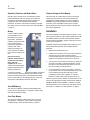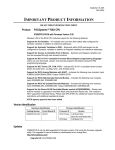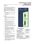
1
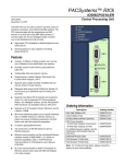
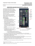
PACSystems™ RX3i
IC695CPU310-EP
Central Processing Unit
GFK-2329S
August 27, 2007
CPU OK
The RX3i CPU can be used to perform real time control of
machines, processes, and material handling systems. The
CPU communicates with the programmer and HMI
devices via a serial port using SNP Slave protocol. It
communicates with I/O and smart option modules over a
dual backplane bus that provides:
■
■
High-speed, PCI backplane for fast throughput of new
advanced I/O.
Serial backplane for easy migration of existing
Series 90-30 I/O
RUN
OUTPUTS DISABLED
I/O FORCE
BATTERY
SYSTEM FAULT
RESET
STOP
CPU310
RUN I/O
ENABLE
RUN OUTPUT DISABLE
COM 1
Features
■
Contains 10 Mbytes of battery-backed user memory
and 10 Mbytes of non-volatile flash user memory.
■
Provides access to bulk memory via reference table
%W.
■
Configurable data and program memory.
■
Programming in Ladder Diagram, Structured Text,
Function Block Diagram, and C.
■
Supports auto-located Symbolic Variables that can
use any amount of user memory.
■
Reference table sizes include 32Kbits for discrete %I
and %Q and up to 32Kwords each for analog %AI
and %AQ.
■
Supports most Series 90-30 modules and expansion
racks. For a list of supported I/O, Communications,
Motion, and Intelligent modules, see the PACSystems
RX3i Hardware and Installation Manual, GFK-2314.
■
Supports up to 512 program blocks. Maximum size for
a block is 128KB.
■
Bit-in-word referencing allows you to specify individual
bits in a WORD reference in retentive memory as
inputs and outputs of Boolean expressions, function
blocks, and calls that accept bit parameters.
■
In-system upgradeable firmware.
■
Two serial ports: an RS-485 serial port and an
RS-232 serial port.
■
Ethernet communications via the rack-based Ethernet
Interface module (IC695ETM001). For details on
Ethernet capabilities, refer to TCP/IP Ethernet
Communications for PACSystems User’s Manual,
GFK-2224.
■
PLC time synchronization to SNTP Time Server on
Ethernet network when used with Ethernet Release
5.0 or later module.
COM1 ACTIVE
COM2 ACTIVE
COM 2
BATT
Ordering Information
Description
Catalog Number
RX3i VME 300Mhz CPU
IC695CPU310
Lithium Battery Pack
IC698ACC701
Auxiliary Battery Module (optional)
IC693ACC302
RX3i Power Supplies
40 Watt High Capacity Universal AC
40 Watt High Capacity 24 VDC
For additional power supplies, see the
PACSystems RX3i System Manual,
GFK-2314.
IC695PSA040
IC695PSD040
[Optional] RS-232 Cable
IC200CBL001
Rx3i Standard 12 Slot Rack
IC695CHS012
Rx3i Standard 16 Slot Rack
IC695CHS016
Note: For Conformal Coat option, please consult the
factory for price and availability.
2
RX3i CPU
GFK-2329S
Operation, Protection, and Module Status
Firmware Storage in Flash Memory
Operation of this module can be controlled by the threeposition RUN/STOP switch or remotely by an attached
programmer and programming software. Program and
configuration data can be locked through software
passwords. The status of the CPU is indicated by the eight
CPU LEDs on the front of the module. (See “LED Operation”
on page 5)
This CPU uses non-volatile flash memory for storing the
operating system firmware. This allows firmware to be
updated without disassembling the module or replacing
EPROMs. The operating system firmware is updated by
connecting a PC compatible computer to the module’s
RS-232 serial port and running the software included with
the firmware upgrade kit.
Battery
Installation
A three-cell lithium battery
pack (IC698ACC701) is
installed as shown in the
figure below. The battery
maintains program and data
memory when power is
removed and operates the
calendar clock. When
replacing the battery, be
sure to install a new battery
before disconnecting the old
one.
Disposal of lithium
batteries must be done in
accordance with federal,
state, and local
regulations. Be sure to
consult with the appropriate
regulatory agencies before
disposing of batteries.
Mode Switch and Battery Compartment
To avoid loss of RAM
memory contents, routine maintenance procedures should
include scheduled replacement of the CPU’s lithium battery
pack. For information on estimating battery life, refer to the
PACSystems CPU Reference Manual, GFK-2222.
User RAM Memory
The CPU has 10 Mbytes of battery-backed CMOS RAM
memory for user data (program, configuration, register data,
and symbolic variable) storage.
User Flash Memory
The CPU has 10 Mbytes of built-in flash memory for user
data (program, configuration, register data, and symbolic
variable) storage. Use of this flash memory is optional.
It is the responsibility of the OEM, system integrator, or end
user to properly install the control system equipment for safe
and reliable operation. Product manuals provide detailed
information about installation, startup, and proper use of the
control system equipment.
Installation should not be attempted without referring to the
PACSystems RX3i Hardware and Installation Manual,
GFK-2314.
1.
Make sure that rack power is off.
2.
Install the CPU module in rack 0. The CPU requires two
slots and can use any slots except the highest
numbered (rightmost) slot. Ensure mounting screws are
tightened to completely secure the CPU in the rack.
3.
Turn on power. The module should power up. When the
CPU has successfully completed initialization, the OK
LED stays on and the RUN and EN LEDs are off. The
CPU is now ready to be programmed.
4.
Connect the battery to either of the battery connectors
on the module. (You can connect the battery at any step
in the installation process but it will begin to drain
immediately unless power is applied. To maximize
battery life, install it after power has been turned on).
After the program has been verified, the mode switch can be
moved to the appropriate operation mode position: RUN I/O
ENABLED, RUN OUTPUT DISABLE, or STOP. The LEDs
indicate the position of the mode switch and status of serial
port activity. For details, see “LED Operation” on page 5.
RX3i CPU
3
GFK-2329S
Serial Cable Lengths and Shielding
Programmer Connection
The programmer can communicate with the CPU via the
serial port 1, serial port 2, or the rack-based Ethernet
interface.
If you connect your programmer via an Ethernet TCP/IP
network, you will need a CAT5 standard Ethernet cable with
RJ-45 connectors. Before connecting the programmer and
RX3i to the Ethernet TCP/IP network you must set the IP
address, using the Initial IP Address software tool. After
setting the IP address, connect the RX3i and the computer
running the programming software to the Ethernet Interface.
For detailed information on programmer connection via
Ethernet TCP/IP, refer to the TCP/IP Ethernet
Communications for PACSystems User’s Manual,
GFK-2224.
For a description of programming functions, consult
Proficy™ Machine Edition Logic Developer-PLC Getting
Started, GFK-1918 and the software online help.
Serial Ports
The CPU has two independent, on-board serial ports,
accessed by connectors on the front of the module. These
ports provide serial interfaces to external devices.
The connection from a CPU serial port COM1 to the serial
port on a computer or other serial device requires a serial
cable. This connection can be made with the IC200CBL001
cable kit or you can build cables to fit the needs of your
particular application. See the PACSystems CPU Reference
Manual, GFK-2222 for more information on serial
communications, cables, and converters.
Maximum cable lengths (the total length from the CPU to the
last device attached to the serial cable) are:
■ Port 1 (RS-232) – 15 meters (50 ft.), shielded cable
optional
■ Port 2 (RS-485) – 1200 meters (4000 ft.), shielded cable
required
Port 1
Port 1 (COM1) is RS-232 compatible. It has a 9-pin, female,
D-sub connector with a standard pin out. This is a DCE (data
communications equipment) port that allows a simple
straight-through cable to connect with a standard AT-style
RS-232 port.
The COM1 Active LED provides the status of serial port
activity.
Protocols Supported
Protocol
Port 1 RS-232 Signals
Port 1
Pin
Number
Port 2
Signal
Name
Description
RTU (slave)
Yes
Yes
SNP Slave
Yes
Yes
1*
NC
No Connection
Yes
2
TXD
Transmit Data
Receive Data
Serial I/O
Yes
Firmware Upgrade
RX3i in STOP/No I/O mode
3
RXD
Message Mode
(C Runtime Library Functions:
serial read, serial write, sscanf,
sprintf)
Yes
4
DSR
Data Set Ready
5
0V
Signal Ground
6
DTR
Data Terminal Ready
7
CTS
Clear To Send
8
RTS
Request to Send
9
NC
No Connection
Yes
Serial Port Baud Rates
Protocol
Port 1
(RS-232)
Port 2
(RS-485)
Modbus RTU
Slave protocol
1200, 2400, 4800, 9600, 19.2K, 38.4K, 57.6K,
115.2K
Message
1200, 2400, 4800, 9600, 19.2K, 38.4K, 57.6K,
115.2K
Firmware
Upgrade via
Winloader
2400, 4800, 9600, 19.2K, 38.4K, 57.6K, 115.2K
SNP Slave
1200, 2400, 4800, 9600, 19.2K, 38.4K, 57.6K,
115.2K
Serial I/O
1200, 2400, 4800, 9600, 19.2K, 38.4K, 57.6K,
115.2K
*
Pin 1 is at the bottom right of the connector as viewed from the
front of the module.
4
RX3i CPU
GFK-2329S
Port 2
Configuration
Port 2 (COM2) is RS-485 compatible. Port 2 has a 15-pin,
female D-sub connector. This port does not support the
RS-485 to RS-232 adapter (IC690ACC901). This is a DCE
port.
The RX3i CPU and I/O system is configured with Machine
Edition PLC-Logic Developer programming software.
The COM2 Active LED provides the status of serial port
activity.
Port 2 RS-485 Signals
Pin
No.
Signal
Name
Description
1*
Shield
Cable Shield
2
NC
No Connection
3
NC
No Connection
4
NC
No Connection
5
+5VDC
Logic Power**
6
RTS(A)
Differential Request to Send
7
0V
Signal Ground
8
CTS(B‘)
Differential Clear To Send
9***
RT
Resistor Termination
10**
RD(A‘)
Differential Receive Data
11
RD(B‘)
Differential Receive Data
12
SD(A)
Differential Send Data
13
SD(B)
Differential Send Data
14
RTS(B)
Differential Request To Send
15
CTS(A’)
Differential Clear To Send
*
Pin 1 is at the bottom right of the connector as viewed from the
front of the module.
**
Pin 5 provides isolated +5VDC power (300mA maximum) for
powering external options.
*** Termination resistance for the RD A’ signal should be
connected on units at the end of the line. To make this
termination, connect a jumper between pins 9 and 10 inside
the 15-pin D-shell.
The CPU verifies the actual module and rack configuration at
power-up and periodically during operation. The actual
configuration must be the same as the programmed
configuration. Deviations are reported to the CPU alarm
processor function for configured fault response. Refer to the
Proficy Machine Edition Logic Developer-PLC Getting
Started Manual, GFK-1918 and the online help for a
description of configuration functions.
Ethernet Global Data (EGD)
Each RX3i CPU supports up to 255 simultaneous Ethernet
Global Data (EGD) exchanges across all Ethernet interfaces
in the PLC. EGD exchanges must be configured in the
programming software and stored into the CPU. The EGD
configuration can also be loaded from the CPU into the
programming software. Both produced and consumed
exchanges can be configured. RX3i CPUs support using
only part of a consumed EGD exchange. EGD exchange
production and consumption can use the broadcast IP
address of the local subnet.
The RX3i CPU supports 2msec EGD exchange production
and timeout resolution. RX3i EGD exchanges can be
configured for a production period of 0, indicating the
exchange is to be produced every output scan. These “as
fast as possible” exchanges are not produced more often
than 2msec. RX3i CPUs support enhanced EGD freshness,
providing better EGD timeliness than Series 90-30 CPU
products.
During EGD configuration, RX3i Ethernet interfaces are
identified by their Rack/Slot location.
Firmware Upgrades
The CPU receives firmware upgrades through a CPU serial
port. To install a firmware upgrade, connect WinLoader to
the CPU RS-232 or RS-485 serial port. Since you are
connecting directly to the CPU, there is no need to specify
the Rack/Slot location. For upgrades to smart modules (the
IC695ETM001, for example), which are performed indirectly
via the CPU serial port, you must specify a rack/slot location.
RX3i CPU
5
GFK-2329S
LED Operation
The following table lists the CPU LED functions during normal operation (after initialization sequence is complete).
LED State
On
Blinking
CPU Operating State
Off
CPU OK
On
CPU has passed its powerup diagnostics and is functioning properly.
CPU OK
Off
CPU problem. RUN and OUTPUTS ENABLED LEDs may be blinking in an error
code pattern, which can be used by technical support for troubleshooting. This
condition and any error codes should be reported to your technical support
representative.
CPU OK, OUTPUTS ENABLED,
RUN
Blinking in unison
RUN
On
RUN
Off
CPU is in boot mode and is waiting for a firmware update through serial port.
CPU is in Run mode
CPU is in Stop mode.
OUTPUTS ENABLED
On
Output scan is enabled.
OUTPUTS ENABLED
Off
Output scan is disabled.
I/O FORCE
On
Override is active on a bit reference.
BATTERY
Blinking
Battery is low.
BATTERY
On
Battery is dead or not attached.
SYSTEM FAULT On
COM1
COM2
Blinking
Blinking
CPU is in Stop/Faulted or Stop/Halted mode.
Signal activity on port.
Specifications*
IC695CPU310
Battery: Memory retention
For estimated battery life under various conditions, refer to the PACSystems CPU
Reference Manual, GFK-2222.
Program storage
Up to 10 Mbytes of battery-backed RAM
10 Mbytes of non-volatile flash user memory
Power requirements
+3.3 VDC: 1.25 Amps nominal
+5 VDC: 1.0 Amps nominal
Operating Temperature
0 to 60°C (32°F to 140°F)
Floating point
Yes
Boolean execution speed, typical
0.195ms per 1000 Boolean contacts/coils
Time of Day Clock accuracy
Maximum drift of 2 seconds per day
Elapsed Time Clock (internal timing)
accuracy
0.01% maximum
Embedded communications
RS-232, RS-485
Serial Protocols supported
Modbus RTU Slave, SNP, Serial I/O
Backplane
Dual backplane bus support: RX3i PCI and 90-30-style serial
PCI compatibility
System designed to be electrically compliant with PCI 2.2 standard
Program blocks
Up to 512 program blocks. Maximum size for a block is 128KB.
Memory
%I and %Q: 32Kbits for discrete
%AI and %AQ: configurable up to 32Kwords
%W: configurable up to the maximum available user RAM
Symbolic: configurable up to 10 Mbytes
*
For environmental specifications and compliance to standards (for example, FCC or European Union Directives), refer to
the PACSystems RX3i Hardware and Installation Manual, GFK-2314.
6
RX3i CPU
GFK-2329S
Release Information
Firmware release 5.00 contains the new features listed in “New Features and Enhancements” on page 8 and corrects the
issues listed in “Problems Resolved by this Revision of Product” on page 7. This release supports Proficy Process Systems
Release 1.00.
Updates
IC695CPU310 can be field-upgraded to firmware version 5.00 using the firmware upgrade utility. The upgrade kit,
44A752290-G16, can be downloaded at no charge from http://support.gefanuc.com or purchased.
Release History
Catalog Number
Firmware Version
Date
IC695CPU310-EP
5.00
Aug. 07
IC695CPU310-EN
3.83
Nov. 06
IC695CPU310-EM
3.82
Jul. 06
IC695CPU310-EL
3.81
May 06
IC695CPU310-DK
3.52
Jan. 06
IC695CPU310-DJ
3.51
Nov. 05
IC695CPU310-DH
3.50
Sep. 05
IC695CPU310-CG
3.12
Aug. 05
IC695CPU310-CF
3.11
Jun. 05
IC695CPU310-CD
3.00
Apr. 05
IC695CPU310-CC
2.90
Dec. 04
IC695CPU310-CB
2.80
Nov. 04
IC695CPU310-CB
2.51
Nov. 04
IC695CPU310-BB
2.51
Jul. 04
IC695CPU310-AA
2.50 (initial release)
Jun. 04
CPU Functional Compatibility
Subject
Description
Programmer Version
Requirements
Proficy® Machine Edition Logic Developer 5.7 is required to use the new Release 5.0 features
with the RX3i CPU.
Proficy Machine Edition Logic Developer 5.5 with Service Pack 2 Sim 4 is required to use the
new CMM serial modules with the RX3i CPU.
Proficy Machine Edition Logic Developer 5.5 with Service Pack 1 is required to use the 8 ETM
feature with the RX3i CPU.
Proficy Machine Edition Logic Developer 5.5 or later must be used to for new features in
PACSystems 3.50 and later.
Proficy Machine Edition Logic Developer 5.0 or later must be used to configure and program
the RX3i. Service Pack 3 is required to support the new features in PACSystems 3.00.
C Toolkit Compatibility
C Toolkit Release 5.00 Build 16C1 is required when the PACSystems CPU contains firmware
Release 5.00 or later.
C Toolkit Release 3.50 Build 34A1 is required for new features in PACSystems Release 3.50
and later (Use of variables in C Blocks).
The C Toolkit for PACSystems is also distributed with Proficy® Machine Edition Logic
Developer 5.0 or greater. Toolkit Release 2.50 build 50A1 or later is required for use with the
RX3i. Please note: The Series 90 Toolkit (IC641SWP709/719) is not compatible with
PACSystems.
Note:
All C blocks must be recompiled using the new toolkit before downloading to a PLC
CPU that contains Release 5.00 firmware.
RX3i CPU
7
GFK-2329S
Backplanes, power
supplies and system
modules
As listed in the PACSystems RX3i System Manual, GFK-2314C or later.
Problems Resolved by this Revision of Product
Subject
Description
GBC30 or "smart" analog In RX3i PLC systems with a very high level of interrupt activity, the CPU could lose
modules could stop
communication with GBC30, ALG222, ALG223, ALG442. This will not occur using Release 5.0.
communicating with PLC
CPU310
PLC Total Used Memory
showed used memory
greater than available
memory
In certain rare occasions after repeated stores of User Logic or Run-Mode-Stores of User Logic,
the PLC may indicate that the Total Used memory exceeds the available User memory in the
PLC. The PLC will subsequently reject any store requests with an error message indicating that
there is not enough memory available, even after clearing User memory. This behavior has
been corrected.
"Address out of range"
message is vague
A new error code (59) has been added to the application faults (group 22). It occurs when a
parameterized subroutine block is called by a block whose %L or %P memory is not large
enough
Reference data not
loaded from flash
In rare instances, during a power up, reference table data was preserved in RAM even if "Load
from Flash" was specified and a good battery was connected to the CPU. This failure only
occurred if the CPU had been powered down while loading reference tables from flash during a
previous power up with the battery connected.
With this release (5.0), a "Controller Sequence Store Failure" Fault appears in the PLC fault
table and the PLC enters STOP FAULT mode when this condition occurs.
Deleting many blocks in a Deleting a large number of blocks (approximately 100 or more) could cause the watchdog timer
run mode store caused
to expire at the default setting. The number of blocks required to cause this increased as the
watchdog expiration
watchdog timeout was increased. This problem has been resolved in version 5.00.
Some very large writes to In previous releases, a very large target, especially one that contained a large %W memory
flash failed
table, may not write to flash successfully. During the download, Proficy Machine Edition would
automatically disconnect and the CPU may enter STOP HALT mode. The error “Fatal Store
Failure – User Flash has been cleared” would appear in the fault table. A power cycle recovered
the PLC to a normal state. This behavior has been corrected.
Incorrect RX3i hot swap Removing an IC693APU300 and replacing a different module into that slot would cause the PLC
action could cause STOP CPU to enter STOP HALT mode. This behavior has been corrected.
HALT mode.
Download of projects
A project containing a large number of EGD produced exchanges with large (more than 200
with many EGD variables variables) exchanges could not be downloaded to the PLC. The PLC fault table displayed a
could fail
"Controller sequence store failure". This behavior has been corrected.
Extraneous fault bits
When a remote rack was lost, all fault locating references for the entire local rack would be set.
were set for remote (e.g. With this release, only the appropriate bits are set.
GNIU, GR7) loss-of-rack
faults
8
RX3i CPU
GFK-2329S
New Features and Enhancements
Scan Set I/O – The SCAN_SET_IO function block scans the I/O of a specified scan set number. Modules are assigned to
scan sets in hardware configuration. An operand of the block specifies whether the Inputs and/or Outputs of the associated
scan set will be scanned. The Scan Set IO function skips modules that do not support DO_IO scanning.
Quality Function Blocks – This group of instructions adds capabilities to determine the quality of the data that is used in an
application. The quality functions will determine whether a data item was transmitted without error from an input device into
an I/O module or from an I/O module to an output device.
Optional Parameters in UDFBs - The ArgPresent function allows logic inside a UDFB or PSB to know if an input argument
for a particular parameter was present or not present. This is useful for optional parameters.
IEC Transitionals - The IEC 61131-3 PLC programming standard defines two edge detector function blocks. The “Rising
edge trigger” R_TRIG and “Falling edge trigger” F_TRIG detect the changing state of a Boolean signal.
Synchronizing the High-resolution Time of Day Clock to an SNTP Network Time Server – This new synchronization
capability allows you to set a consistent time across multiple systems. Once the CPU TOD clock is synchronized with the
SNTP time, all produced EGD exchanges will use the CPU’s TOD for the time stamp. Using this feature requires the Ethernet
Advanced User Parameter “ncpu_sync” and a COMMREQ in the user logic. Also, use of this feature requires both CPU
firmware release 5.00 or later and Ethernet firmware release 5.00 or later.
CPU Restrictions and Open Issues
Subject
Description
Battery installation
When installing a new battery, when there currently is no battery installed, the battery
must be installed while the CPU has power. Failing to follow this procedure could
result in the CPU not powering up.
If a battery is installed while power is off (and there was no battery previously
installed), and the CPU fails to power up, simply remove the battery, power cycle the
CPU and then install the battery.
Hot Swapping some Analog
modules slowly may result in
modules not being recognized
Occasionally during a hot insertion (hot swap) of IC695 Non-Isolated Analog Input
Modules, input channels may take up to 2 seconds to reflect actual input values after
the module OK bit is enabled in the module status word. This delay has only occurred
when the hot insertion has been done slowly (i.e. approximately 1.5 seconds to insert
the module)
Ethernet Disconnect During
Word-for-Word Change
If the Ethernet connection is broken during a word-for-word change, the programmer
may not allow a subsequent word-for-word change after reconnecting due to the fact
that it thinks another programmer is currently attached. If this occurs, you should go
offline and then back online again.
Simultaneous Clears, Loads
and Stores Not Supported
Currently, PACSystems CPUs do not support multiple programmers changing CPU
contents at the same time. The programming software may generate an error during
the operation. Simultaneous loads from a single PLC are allowed.
Hardware Configuration and
Initial Values May Not Load
From Flash
If no user logic exists in the CPU RAM when a write to flash is performed, the CPU
may not properly load from flash after a power cycle. In order to guarantee proper
power up from flash, insure that both hardware configuration and logic have been
stored to RAM before writing to flash.
Power Cycle During Write to
Flash
If the CPU is power cycled during the process of writing to flash, and is configured to
power up from flash, a fault will be generated on power up.
Hardware Configuration Not
Equal After Changing Target
Name
If the user stores a hardware configuration to flash that sets “Logic/Config Power up
Source” to “Always Flash” or “Conditional Flash” and then subsequently changes the
name of the target in the programming software, the hardware configuration will go Not
Equal and will not Verify as equal.
PLC and IO Fault Tables May
Need to be Cleared Twice to
Clear Faulted State
Both PLC and IO fault tables may need to be cleared to take the CPU out of Stop/Fault
mode. If one of the tables contains a recurring fault, the order in which the tables are
cleared may be significant. If the CPU is still in Stop/Fault mode after both tables are
cleared, try clearing the fault tables again.
RX3i CPU
9
GFK-2329S
Subject
Description
Setting Force On/Off by
Storing Initial Value
Once a force on or force off has been stored to the PLC, the user cannot switch from
force on to force off or vice-versa directly by downloading initial values. The user can
turn off the force by doing a download, and then change the force on or off by another
download.
Number of Active Programs
Returned as Zero
The SNP request Return Controller Type and ID currently returns the number of active
programs as zero.
Serial I/O Failure at 115K
During Heavy Interrupt Load
Rare data corruption errors have been seen on serial communications when running at
115K under heavy interrupt load on the PLC. Under heavy load applications, users
should restrict serial communications to 57K or lower.
SNP ID not always provided
Unlike the Series 90-30, the RX3i CPU’s SNP ID will not appear in the Machine Edition
programmer Show Status display. Service Request 11 will always return zeros.
Second programmer can
change logic while in Test &
Edit mode
While currently active in a Test and Edit session using Machine Edition on one PC,
Machine Edition running on another PC is not prevented from storing new logic to the
PLC.
Must Have Logic If PoweringUp From Flash
If the application will configure the CPU to retrieve the contents of flash memory at
power-up, be sure to include logic along with hardware configuration when saving to
flash memory.
Two loss of module faults for
Universal Analog Module
Occasionally, the hot removal of the Universal Analog Input Module (IC695ALG600)
results in two “Loss of I/O Module” faults instead of one.
Power up of HSC may take as
long as 20 seconds
As power is applied to a 90-30 High-Speed Counter, the "module ready" bit in the
status bits returned each sweep from the module may not be set for as long as 20
seconds after the first PLC sweep, even though there is no "loss of module" indication.
I/O data exchanged with the module is not meaningful until this bit is set by the
module. For details, see “Data Transfer Between High Speed Counter and CPU” in the
Series 90-30 High Speed Counter User’s Manual, GFK-0293C.
Info fault at power up
Intermittently during power-up, an Informational non-critical CPU software fault may be
generated with fault extra data of 01 91 01 D6. This fault will have no effect on the
normal operation of the PLC. But, if the hardware watchdog timer expires after this
fault and before power has been cycled again, then the outputs of I/O modules may
hold their last state, rather than defaulting to zero.
Extended Memory Types for IO
Triggers
%R, %W and %M cannot be used as IO triggers.
Possible Machine Edition
inability to connect
Infrequently, an attempt to connect a programmer to a PLC via Ethernet will be
unsuccessful. The normal connection retry dialog will not be displayed. Rebooting the
computer that is running the programmer will resolve the behavior.
SNP Update Datagram
message
If an Update Datagram message requests 6 or less bits or bytes of data, the PLC will
return a Completion Ack without Text Buffer. The protocol specifies that the returned
data will be in the Completion Ack message, but it may not be.
GBC30 may not resume
operation after power cycle
In rare instances, a GBC30 in an expansion rack may not resume normal operation
after a power cycle of either the expansion rack or the main rack.
Configuration of third-party
modules
Do not specify a length of 0 in the configuration of a third-party module. The module
will not work properly in the system.
Power supply status after CPU
firmware update
The PLC will report a “Loss of or missing option module” fault for the IC695PSD140
RX3i power supply following an update of PLC CPU firmware. Also, the slot will
appear empty in the programmer’s online status detail view. The power supply
continues to operate normally. Power cycle to restore normal status reporting.
Power supply status after
power cycling
Rarely, turning a power supply on or off may not result in an add or loss fault. Also, the
slot will appear empty in the programmer’s online status detail view. The power supply
continues to operate normally. Power cycle to restore normal status reporting.
Don’t use multiple targets
In a system in which the hardware configuration is stored from one target and logic is
stored from a different target, powering-up from flash will not work. The observed
behavior is that, following a power up from flash, ME reports hardware configuration
and logic "not equal".
10
RX3i CPU
GFK-2329S
Subject
Description
Missing “Loss of terminal
block” fault
The IC695ALG600/608/616 analog input modules do not produce a “Loss of terminal
block” fault when hardware configuration is stored or the module is hot-inserted, and
the terminal block is not locked into place.
Sequence Store Failure
In systems with very large hardware configurations, it is possible to encounter a “PLC
Sequence Store Failure” error when writing the configuration to flash. To work around
this error, either:
1. Perform an explicit clear of flash prior to performing the write.
2. Increase the operation timeout used by Machine Edition software prior to
performing the write.
IC694MDL754: Must configure
module status bits
Always configure 16 bits of module status when using this module. Configuring 0 bits
of module status will result in invalid data in the module’s ESCP status bits.
IC695ALG600 Lead Resistance
Compensation setting
A configuration store operation will fail if a channel is configured for 3-wire RTD and
Lead Resistance Compensation is set to Disabled. A Loss of Module fault will be
logged in the I/O Fault table at the end of the store operation. To recover the lost
module, the configuration must be changed to enable Lead Resistance Compensation
and module must be power cycled.
C Toolkit PlcMemCopy
Documentation Incorrect
This routine does allow the destination and source pointers to be outside of reference
memory. If the destination points to discrete reference memory, overrides and
transitions will be honored. Note that the header for PlcMemCopy has been updated in
Release 3.50 of the C toolkit.
Flash clear operation may fail
unexpectedly
Occasionally flash clears may fail when the CPU is configured to load hardware config
and logic from flash with a battery attached. If this occurs, remove the battery and
power cycle to resolve the issue.
WinLoader may stop operating
On computers running Windows 2000 and using some versions of Symantec Antivirus
protection, WinLoader will fail if used in advanced mode. Recovery requires cycling
the computer's power.
Storing a Configuration w/EGD
to Mismatched Module
Prevents Future Stores
Storing a configuration that causes a mismatch for an Ethernet module with EGD
configured causes the CPU to get into a state where all future stores will fail. The
remedy is pulling the battery and power cycling.
Issues Related to the IC693DNM200 DeviceNet Master Module
Please see GFK-2194C or later for open issues related to the IC693DNM200 DeviceNet Master Module.
RX3i CPU
11
GFK-2329S
CPU Operational Notes
Subject
Description
Length of Serial
I/O buffer
(Release 5.0 or later) The "Set Up Input Buffer Function" always allocates a buffer containing
2049 bytes. This is one byte more than previous PACSystems releases.
Important
Installation
Instructions for
Battery
The CPU unit is shipped with the battery located behind the battery door on the faceplate, but not
connected. Do not connect the battery until the CPU is installed in the rack and the rack is
powered on. The battery may then be attached to either of the two terminals in the battery
compartment. Once that is done, the CPU may be powered down and normal battery backup
operation will begin. To save battery life, do not connect the battery for the first time until the CPU
is powered up.
LD-PLC
operations
Machine Edition LD-PLC no longer supports a function that connects to the PLC, downloads, then
disconnects from the PLC. The connect and download functions are now separate. To perform a
download to the PLC, you must first connect to the PLC.
Logic Executed in
Row Major
Instead of Column
Major
Logic execution in PACSystems RX3i is performed in row major order (similar to the Series
90-30). This is different from the Series 90-70, which executes in column major order. This
means that some complicated rungs may execute slightly differently on PACSystems RX3i and
Series 90-70. For specific examples, see the programming software on-line help.
NaN Handled
Differently Than in
90-30
The PACSystems RX3i CPU may return slightly different values for Not A Number as compared
to Series 90-30 CPUs. In these exception cases (e.g., 0.0/0.0), power flow out of the function
block is identical to Series 90-30 operation and the computed value is still Not A Number.
PID Algorithm
Improved
The PID algorithm used in PACSystems has been improved and therefore PID will function
slightly differently on PACSystems RX3i than on the Series 90-30. The differences are that the
elapsed time is computed in 100 μS instead of 10 mS units. This smoothes the output
characteristic, eliminating periodic adjustments that occurred when the remainder accumulated to
10mS.
Also, previous non-linear behavior when the integral gain is changed from some value to 1
repeat/second was eliminated.
Some Service
Requests different
from 90-30 or no
longer supported
Service Requests 6, 15, and 23 have slightly different parameters. Refer to GFK-2222.
PACSystems PLCs support Service Request 26/30 functionality via fault locating references.
Service Request 13 requires a valid value in the input parameter block (Refer to GFK-2222 for
details). On the Series 90-30 and Series 90-70 the parameter block value was ignored.
Service Requests 48 and 49 are no longer supported (there is no auto-restart) because most
faults can be configured to be not fatal.
IL and SFC
IL and SFC are not available.
DO I/O Instruction
The Series 90-30 Enhanced DO I/O instruction is converted to a standard DO I/O instruction (the
ALT parameter is discarded and ignored.)
END Instruction
The Series 90-30 END instruction is not supported. Alternate programming techniques should be
used.
Non-nested
JUMP, LABEL,
MCR, & ENDMCR
Instructions
Non-nested JUMPs, LABELs, MCRs, & ENDMCRs are translated to the corresponding nested
JUMPs, LABELs, MCRs, & ENDMCRs when converting from Series 90-30 to PACSystems RX3i.
Changing IP
Address of
Ethernet Interface
While Connected
Storing a hardware configuration with a new IP address to the RX3i while connected via Ethernet
will succeed, then immediately disconnect because the RX3i is now using a different IP address
than the Programmer. You must enter a new IP address in the Target Properties in the Machine
Edition Inspector window before reconnecting.
Duplicate Station
Address for
Modbus Will
Conflict with
Other Nodes
The default serial protocol for the RX3i is Modbus RTU. The default Station Address is 1. If the
PLC is added to a multi-drop network, care must be taken that the PLC is configured with a
unique Station Address. Nodes with duplicate Station Addresses on the same network will not
work correctly.
12
RX3i CPU
GFK-2329S
Subject
Description
Timer Operation
Care should be taken when timers (ONDTR, TMR, and OFDTR) are used in program blocks that
are NOT called every sweep. The timers accumulate time across calls to the sub-block unless
they are reset. This means that they function like timers operating in a program with a much
slower sweep than the timers in the main program block. For program blocks that are inactive for
large periods of time, the timers should be programmed in such a manner as to account for this
catch up feature.
Related to this are timers that are skipped because of the use of the JUMP instruction. Timers
that are skipped will NOT catch up and will therefore not accumulate time in the same manner as
if they were executed every sweep.
Constant Sweep
Constant Sweep time, when used, should be set at least 10 milliseconds greater than the normal
sweep time to avoid any over-sweep conditions when monitoring or performing on-line changes
with the programmer. Window completion faults will occur if the constant sweep setting is not
high enough.
Large Number of
COMMREQs Sent
to Module in One
Sweep Causes
Faults
A large number of COMMREQs (typically greater than 8) sent to a given board in the same sweep
may cause Module Software faults to be logged in the PLC fault table. The fault group is
MOD_OTHR_SOFTWR (16t, 10h) and the error code is COMMREQ_MB_FULL_START (2).
When this occurs, the “FT” output of the function block will also be set. To prevent this situation,
COMMREQs issued to a given board should be spread across multiple sweeps so that only a
limited number (typically 8 or less) of COMMREQs are sent to a given board in each sweep. In
addition, the FT output parameter should be checked for errors. If the FT output is set (meaning
an error has been detected), the COMM_REQ could be re-issued by the application logic.
C Block Standard
Math Functions Do
Not Set errno
In C Blocks, standard math functions (e.g. sqrt, pow, asin, acos) do not set errno to the correct
value and do not return the correct value if an invalid input is provided.
Upgrading Firmware
The process of upgrading the CPU firmware with the WinLoader utility may fail when multiple IO
modules are in the main rack, due to the time it takes to power cycle the rack system. If the
upgrade process fails, move the CPU to a rack without IO modules and restart the upgrade
process.
Winloader initial connect baud rate is fixed at 19200 baud. Note that the firmware download will
occur at 115.2K baud by default.
Note that if you have hyperterm open on a port, and then try to use Winloader on the same port,
Winloader will often say “Waiting for Target” until the hyperterm session is closed.
Hot Swap
Hot Swap of power supplies or CPUs is not supported in this release
Serial Port
Configuration
COMMREQs
With the following combination of circumstances, it is possible to render serial communications
with the CPU impossible:
User configuration disables the Run/Stop switch
User configures the power up mode to Run or Last
Logic is stored in FLASH and user configures CPU to load from FLASH on power up
User application issues COMMREQs that set the protocol on both of the serial ports to
something that does not permit communications to the ME programmer.
Incorrect
COMMREQ Status
For Invalid Program
Name
The program name for PACSystems is always "LDPROG1". When another program name is used
in a COMM_REQ accessing %L memory, an Invalid Block Name (05D5) error is generated.
FANUC I/O Master
and Slave operation
Scan sets on the master do not work properly for the first operation of the scan set after entering
RUN mode. They do work properly for subsequent scans.
After downloading a new hardware configuration and logic, a power cycle may be required to
resume FANUC I/O operation.
Use PLCs of similar performance in FANUC I/O networks. If a master or slave is located in an
RX3i system, the other PLCs should be RX3is or Series 90-30 CPU374s.
Repeated power up/down cycles of an expansion rack containing FANUC I/O slaves may result in
failure of the slaves’ operation, with the RDY LED off.
Lost count at power
up for Serial IO
Processor
The serial IO Processor (IC693APU305) will lose the first count after every power up or every
time the module receives a configuration.
RX3i CPU
13
GFK-2329S
Subject
COMMREQ Status
Words Declared in
Bit Memory Types
Must Be ByteAligned
Description
In previous releases, the CPU allowed configuration of COMMREQ Status Words in bit memory
types on a non-byte-aligned boundary. Even though the given reference was not byte-aligned,
the firmware would adjust it the next-lowest byte boundary before updating status bits, overwriting
the bits between the alignment boundary and specified location. To ensure that the application
operates as expected, release 3.50 requires configuration of COMMREQ Status Words in bit
memory types to be byte-aligned. For example if the user specified status bit location of %I3, the
CPU aligns the status bit location at %I1. Release 3.50 firmware requires the user to specify the
appropriate aligned address (%I1) to ensure that the utilized location is appropriate for their
application. Note that the actual reference location utilized is not changed, but now is explicitly
stated for the user.
Installation in Hazardous Locations
The following information is for products bearing the UL marking for Hazardous Locations:
WARNING - EXPLOSION HAZARD - SUBSTITUTION OF COMPONENTS MAY IMPAIR SUITABILITY FOR
CLASS I, DIVISION 2;
WARNING - EXPLOSION HAZARD - WHEN IN HAZARDOUS LOCATIONS, TURN OFF POWER BEFORE
REPLACING OR WIRING MODULES; AND
WARNING - EXPLOSION HAZARD - DO NOT CONNECT OR DISCONNECT EQUIPMENT UNLESS
POWER HAS BEEN SWITCHED OFF OR THE AREA IS KNOWN TO BE NONHAZARDOUS.
EQUIPMENT LABELED WITH REFERENCE TO CLASS I, GROUPS A, B, C & D, DIV. 2 HAZARDOUS
LOCATIONS IS SUITABLE FOR USE IN CLASS I, DIVISION 2, GROUPS A, B, C, D OR NON-HAZARDOUS
LOCATIONS ONLY
The tightening torque range for the control terminals is 9.6-11.5 in. lb. Use only wire rated for 90°C. Be sure to
observe any additional ratings that are provided with the modules.
Batteries: Replace Battery with Matsushita Part No. BR2477A Only. Use of another battery may present a risk
of fire or explosion.” “Caution, Battery may explode if mistreated. DO NOT recharge, disassemble or dispose
of in fire.” The correct battery type is available as Accessory Kit IC698ACC701.