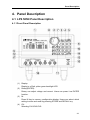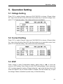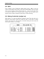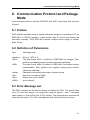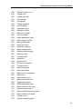
1
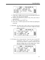
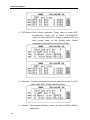
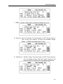
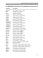
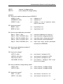
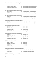
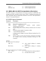
LPS 505N Programmable DC Power Supply User’s Manual Edition July 2005 P/N ZOM-505ME Storage. Freight. Maintenance. Disposal Legal Notices The information in this document is subject to change without notice. MOTECH makes no warranty of any kind with regard to this manual, including, but not limited to, the implied warranties of merchantability and fitness for a particular purpose. MOTECH shall not be held liable for errors contained herein or direct, indirect, special, incidental or consequential damages in connection with the furnishing, performance, or use of this material. MOTECH 6F, NO. 248, Pei-Shen Rd., Sec. 3, Shen Keng Hsiang, Taipei Hsien 222, Taiwan Copyright Notices. Copyright 2005 MOTECH, all rights reserved. Reproduction, adaptation, or translation of this document without prior written permission is prohibited, except as allowed under the copyright laws. Warranty Warranty All MOTECH instruments are warranted against defects in material and workmanship for a period of one year after date of shipment. MOTECH agrees to repair or replace any assembly or component found to be defective, under normal use during this period. MOTECH's obligation under this warranty is limited solely to repairing any such instrument, which in MOTECH's sole opinion proves to be defective within the scope of the warranty when returned to the factory or to an authorized service center. Transportation to the factory or service center is to be prepaid by purchaser. Shipment should not be made without prior authorization by MOTECH. This warranty does not apply to any products repaired or altered by persons not authorized by MOTECH, or not in accordance with instructions furnished by MOTECH. If the instrument is defective as a result of misuse, improper repair, or abnormal conditions or operations, repairs will be billed at cost. MOTECH assumes no responsibility for its product being used in a hazardous or dangerous manner either alone or in conjunction with other equipment. High voltage used in some instruments may be dangerous if misused. Special disclaimers apply to these instruments. MOTECH assumes no liability for secondary charges or consequential damages and in any event, MOTECH's liability for breach of warranty under any contract or otherwise, shall not exceed the purchase price of the specific instrument shipped and against which a claim is made. Any recommendations made by MOTECH for use of its products are based upon tests believed to be reliable, but MOTECH makes no warranty of the results to be obtained. This warranty is in lieu of all other warranties, expressed or implied, and no representative or person is authorized to represent or assume for MOTECH any liability in connection with the sale of our products other than set forth herein. MOTECH INDUSTRIES INC. 6F, NO. 248, Pei-Shen Rd., Sec. 3, Shen Keng Hsiang, Taipei Hsien, 222, Taiwan Telephone : (886-2) 2662-5093 Facsimile : (886-2) 2662-5097 Email : t&[email protected] URL : www.motech.com.tw Storage. Freight. Maintenance. Disposal ※※※ Storage. Freight. Maintenance. Disposal ※※※ Storage When don’t use the device, please pack it properly and store under a good environment. (The packing is no needed when the device under appropriate environment.) Freight Please use the original packing material when move the device. If the packing material is missing, please use the equivalent buffer material to pack and mark it fragile and waterproof to avoid the device damage during movement. The device is precision equipment, please use qualified transportation as possible. And, please avoid heavy hitting to damage the device. Maintenance There is no maintenance operation for the general user (except for the note in the manual). Please contact our company or agent when the device occurred the user judgment abnormal. Don’t maintain by yourself to avoid occurred unnecessary danger and serious damage to the device. Disposal When the device in badly condition and can’t be used or repaired, please discard it according to your company disposal procedures or local legal procedures. Don’t discard arbitrary to avoid polluting environment. Index Index 1. Introduction.................................................................................................................1-1 1.1 An Overview of Product ...............................................................................1-1 1.2 Features .........................................................................................................1-1 2. Specification ...............................................................................................................2-1 3. Notices before Using ................................................................................................3-3 3.1 Confirm Attachment before Using ..............................................................3-3 3.2 The Description of Using .............................................................................3-3 3.3 Ambient Environment...................................................................................3-3 3.4 Storage ...........................................................................................................3-3 3.5 Power-Line Voltage ......................................................................................3-4 3.6 Fuse ................................................................................................................3-4 3.7 Warming up....................................................................................................3-4 3.8 End Test..........................................................................................................3-4 4. Panel Description ......................................................................................................4-1 4.1 LPS 505N Panel Description ......................................................................4-1 4.1.1 Front Panel Description .......................................................................................... 4-1 4.1.2 Rear Panel Description........................................................................................... 4-9 5. Operation Setting ......................................................................................................5-1 5.1 Voltage setting...............................................................................................5-1 5.2 Current setting...............................................................................................5-1 5.3 OVP.................................................................................................................5-1 5.4 OCP ................................................................................................................5-2 5.5 Rotary controller (During voltage output) ..................................................5-2 6. RS-232/RS-485/USB/Etheret communication protocol and package mode6-1 6.1 Preface ...........................................................................................................6-1 6.2 Definition of parameters...............................................................................6-1 6.3 Error message list.........................................................................................6-1 6.4 MOTECH LPS series compatible command list ......................................6-5 6.5 IEEE-488.2 & SCPI Compatiable information ..........................................6-9 6.5.1 SCPI frequent command ........................................................................................ 6-9 6.5.2 SCPI command for subsystem............................................................................ 6-10 6.6 7. Rules of statuts definition ..........................................................................6-12 Accessories ................................................................................................................7-1 Introduction 1. Introduction 1.1 An Overview of Product Motech LPS 505N is a triple outputs and programming DC power supply. LPS 505N comes with 12 bits resolution. Total 210W power output is provided by triple independent outputs. Double output provide 0~30V/3A, the other one provides 0~10V/5A 30W. For the 0~10V/5A output, users can use auto-ranging while constant 30W power output. This is the unique feature and it differs from other traditional power supplies. Those two 0~30V/3A outputs are required to output in serial or parallel mode. Tracking function is convenient and changeable for users in circuit application. LPS 505N has rotary and number key for user to easily operation. The configuration can be stored in memory (Max.100). Timer (1 sec~100 hrs) control when output can be switched off. It can provide the safety for burning room and electroplating application. OVP, OCP can be controlled and monitored by front panel. Users will not change the original setting because of the key lock function. When source and load change, LPS 505N has stable output due to 0.01% load and line regulation and max. 50 us respond time. Average measurement time is 50 ms to increase the production quantity. 1.2 Features 1. Triple output: Voltage Ranges : 0~30V (CH1&CH2) / 0~10V (CH3) Current Ranges : 0 ~ 3A (CH1&CH2) /0~ 5A (CH3) Power Ranges : 0 ~ 90W (CH1&CH2) / 0~30W (CH3) The third output is an auto-ranging output. Users can change voltage and current as they want based on maximum 30W output. For example, output 10V/3A or 6V/5A voltage and current should be within the output range. 2. Digital rotary, number key, function key setting: Digital rotary can change voltage rapidly. Simulate the surge of the voltage output. It provides the solution for the trigger circuit testing. User can set up voltage by number key quickly. It differs from original VR adjusting. Function key provide users operation more friendly and easily. 3. Precious measurement on voltage & current: Besides precise output, LPS 505N provides voltage and current measurement. Users can reduce the measurement equipment budget and space. 1-1 Introduction 4. Memory and timer function: LPS 505N has large memory to memorize 100 settings. Operators are unnecessary to remember the settings. It can be easily to recall the settings. For safety issue, timer function will automatically switch off the machine when they are burning in burning room. LPS 505N can also provides time control good current resolution for electroplate application as customers’ need. 5. OVP, OCP & lock protection function: OVP, OCP provide the safety for the laboratory. The setting will not be changed due to the key lock function. 6. Series, parallel mode: In serial mode, CH1/CH2 can output maximum 60V with positive/negative output. It can be used for OP circuit design. In parallel mode, CH1/CH2 can output 6A maximum. 7. Dual tracking: Users only needs to setup CH1 output voltage and current, LPS 505N will output the same voltage/current at CH2. This is convenient to test two samples at the same time. 1-2 Specification 2. Specification Model LPS 505N Channel NO. CH1 & CH2 CH3 Output Voltage 0~30V 0~15V Output Current 0~3A 0~5A 90W 30W Output Power (CH3 Auto Ranging) Line Regulation ±(% of output +offset) Voltage 0.01% + 2mV Current 0.01% + 300uA Load Regulation ±(% of output +offset) Voltage ≦3mV Current ≦5mV 0.01% + 300uA Ripple and Noise Normal Mode Voltage 300uVrms / 3mVpp 1mVrms / 20mVpp Normal Mode Current <1mA <5mA Programming 10mV / 1mA 10mV / 2mA Readback 10mV / 1mA 3mV / 2mA Resolution Programming Accuracy ±(% output +offset) Voltage 0.05% + 20mV 0.05% + 6mV Current 0.05% + 3mA 0.05% + 4mA Readback Accuracy ±(% output +offset) Voltage 0.05% + 20mV 0.05% + 6mV Current 0.05% + 3mA 0.05% + 4mA Temperature Coefficient per℃ ±(% output +offset) Voltage <0.1% + 3mV Current <0.2% + 2mA Tracking Accuracy ±(% of output +offset) Voltage Transient Response Time Stability﹐constant output & temperature 0.1% + 40mV <50uS ±(% of output +offset)﹐8hrs Voltage <0.2% + 2mV Current <0.1% + 1mA 2-1 Specification Voltage Programming Speed Rising Time at Full Load 1mSec 2mSec Rising Time at No Load 1mSec 2mSec Falling Time at Full Load 5mSec 8mSec Falling Time at No Load 300mSec 100mSec General AC Line Input Voltage Ranges 115/220 VAC ± 10%(47Hz ~ 63Hz) Temperature Ratings Operating( 0°C ~ 40°C),Storage (- 10°C ~ 70°C) Common-Mode Voltage Dimensions ( W×H×D )mm Weight ±240Vdc ( 216 × 135 × 432 ) 6.5 kg LPS 505N Feature: LCD display, triple independent output and display on LCD CH3 auto-ranging output Low Ripple、Low Noise Number and function key Store and recall settings (100) Timer (1 sec ~ 100 hours) Precise voltage and current measurement OVP, OCP and key lock Serial and parallel mode Dual Tracking Mode Average measurement time 50m sec Standard RS232, USB interface Option: I/O port, GPIB, LAN interface 2-2 Notices before Using 3. Notices before Using 3.1 Confirm Attachment before Using Please follows the below items to protect your rights as you receive this instrument. 1. If there is ruin or scratch bad condition on product overlook. 2. The standard attachment as table 10-1, please confirm if there is any missing. ※ If above conditions, please inform us for prompt service. 3.2 The Description of Using The tester is an accurate instrument. Please read through this manual to prevent improper operation and arbitary using from causing this instrument damaged. Please calibrate once a year for keeping accuracy. 3.3 Ambient Environment 1. Do not use the tester in a dusty, vibrating, sunlight and corrosive gas. Please use this instrument under the ambient temperature is 0~40°C and the relative humidity is 20%~80%. If the temperature is over 40°C, please don’t use temporary until the temperature is down to normal. Please check to avoid the unit damage which result from over temperature. 2. The tester is equipped with a cooling fan on the rear panel to keep the internal temperature down, so adequate ventilation should be ensured. The tester should be located at least 10cm from any object or wall behind it. Do not block the ventilation holes to keep the tester in good precision. 3. The tester has been carefully designed to prevent the noise from the AC power source. However, it should be used in the noise-free environment as low as possible. If noise is inevitable, please install a power filter. 3.4 Storage The tester should be stored within the temperature range -20°C ~ 70°C, the relative humidity 80% RH. If the unit is not to be in use for a long time, please store it in the original or similar package and keep it from direct sunlight and humidity. 3-3 Notices before Using 3.5 Power-Line Voltage The tester is an instrument which uses AC power 115V/230V 50Hz/60Hz. Before plugging in the power cord, make sure the power switch is in the off position and the voltage of the rear panel is the same as the required voltage. 3.6 Fuse There is one fuse installed in the rear panel. When replacing the fuse, please notice the following: 1. Please turn off the power and disconnect the AC power cord and all the other connections to the power supply. 2. The checking of fuse can’t sure with the eyes, the testing value under 15Ω is normal. 3. When replacing the fuse, the cap jut out the rear panel on fuse stand using flat type screwdriver or pressing softly by hand. Mark Center Voltage Range Fuse 115 115V 100V~125V Slow 220 220V 200V~250V Slow Warning: For continues protection against fire hazard, replace only with the same type and rating of fuse as specified. 3.7 Warming Up This tester activates at power on. However, in order to meet the accuracy in the specification, please warm it up for 30 minutes or longer. 3.8 End Test When tests are done and the tester is not in use or need to leave for a while during usage, make sure to turn off the power switch. 3-4 Panel Description 4. Panel Description 4.1 LPS 505N Panel Description 4.1.1 Front Panel Description (1) (2) (3) (4) Display: Display is a 20x4 yellow green backlight LCD Rotary(ENTER): Rotary can adjust voltage and current. Users can press it as ENTER function. M: Press M key to memory configuration display. Users can select which setting to store and recall by pressing STORE and RECALL key. CH: Selecting CH1/CH2/CH3 4-1 Panel Description (5) ON/OFF: Switching power output on or off of the instrument (6) Number Key: Input number by number key. To set the voltage or current, press the “V” or “A” key after the number input. (7) ►(STORE): When the output is on, press the key to move the cursor to select digit for adjustment. Users can adjust the digit by rotary. In memory function, store into memory by pressing this key. (8) ◄(RECALL): When the output is on, press the key to move the cursor to select digit for adjustment. Users can adjust the digit by rotary. In memory function, recall from the memory by pressing this key. (9) DISP: Press this key to select the display to show the voltage/current or power/resistance readout. (10) V(Voltage): Press this key to set voltage after number input. (11) A(Current): Press this key to set current after number input. (12) Config: Press this key to enter the configuration setting. There 16 items to be set in this mode. 1. Timer: The initial value is OFF. Press the rotary to enter timer configuration. 4-2 Panel Description A. Using rotary or ◄►to move the cursor onto the digit and input the number. Timer: 00:00:00 (HH:MM:SS) B. Switching CH1/CH2/CH3 by press CH key. Then press rotary to switch ON/OFF C. Start Timer when press ON/OFF key D. Press rotary + CLEAR to pause the timer. Restart by repeating the same step 2. TRACKING: The initial value is OFF, switch to ON by pressing the rotary. The CH2 will have the same voltage and current setting as the CH1. 3. OVP setting: Over voltage protection. Press the rotary to enter OVP Configuration. Press “CH” to select CH1/CH2/CH3. Users can press ON/OFF to enable or disable OVP and input the voltage value via the number keys. Please remember to press rotary to save the settings. 4-3 Panel Description 4. OCP setting: Over current protection. Press rotary to enter OCP Configuration. Press “CH” to select CH1/CH2/CH3. Users can press ON/OFF to enable or disable OCP and input current value via the number keys. Please remember to press rotary to save the settings. 5. Baud rate: Transmission speed. Users can select baud rate for 1200, 2400, 4800, 9600, 19200, 38400 by rotary. 6. Interface: Transmission interface. Users can select RS232, USB by using rotary. 4-4 Panel Description 7. BEEP: Buzzer. Press rotary to switch the buzzer on or off. 8. Key lock: Key lock function. The initial value is OFF. Press rotary to turn on key lock function. All keys are disabled except Rotary + CLEAR can disable the key lock. 9. Parallel out: Parallel output. The initial value is OFF. Press rotary to turn on parallel output. The total output current is 6A because the CH1 and CH2 are connected parallelized. 4-5 Panel Description 10. Serial out: Serial output. The initial value is OFF. Press rotary to turn on serial output. The total output voltage is 60V because the CH1 and CH2 are connected serialized. 11. Address: GPIB address setting. Acceptable range is 00~31. Users can input the number and press rotary to save the settings. 12. Hot Key: Express function key. The initial value is OFF. Press rotary to turn on hot key. The users can recall the correspondent settings from the memory via input 0~9. 13. Initial Mode: Memorize the settings before the instrument shutdown. The initial value is OFF. Press rotary to turn on the function. When the function is enable, all setting will be saved before the instrument shutdown and recalled after the instrument power on. 4-6 Panel Description 14. Out Mode: Output mode. The initial value is single. Press rotary to switch to multi mode. In the multi mode, CH1/CH2/CH3 output on or off will synchronize by press the ON/OFF key. 15. Factory Preset:Reset to default settings 16. Back Main Menu:Quit configuration and save the settings PS : Setting will be saved, after the last item (16. Back Main Menu) is entered. 4-7 Panel Description (13) ﹒(LCL): (14) (15) (16) (17) 4-8 Use as a decimal point. Or, users can press the key to reset to LOCAL mode when in REMOTE connection. CLEAR(ESC): Clear the number input. Or, back to the previous display. Power Switch(POWER ON/OFF) Power switch, █ is OFF, ▄ is ON. Please read Notices before Using before power on. CH1/CH2/CH3 Power Output: Please recognize the mark on front panel and notice the positive and negative pole. GND: Connected to the ground. Please note that the power core has the third pin, or it will not work. Panel Description 4.1.2 Rear Panel Description (18) AC Power Input: The plug connected to the AC source. It uses for 115V/220V. (19) Fuse: The fuse used for power source. When the switch set to 115V, using 5A slow fuse; set to 220V, using 2.5A slow fuse. (20) Remote Sense/Local Sense dip switch: When the switch set to ON, it becomes to local sense mode, which means positive pole connect to +Sense, negative pole connect to -Sense. When the switch set to OFF, it becomes to remote sense mode. It has voltage compensation when it collaborate with ±Sense. (21) CH1 ±S / CH2 ± S: When the switch set to OFF, it becomes to local sense mode. It has 4-9 Panel Description (22) (23) (24) (25) (26) 4-10 voltage compensation when it collaborates with ±Sense. CH1 +Sense and positive pole connect to DUT positive pole. CH1 -Sense and negative pole connect to DUT negative pole. RS232 Interface USB Interface 115V/220V Power switch (At the bottom of the instrument near the front panel) Cooling Fan: Depends on the current of the load, it will adjust the rotation speed of the fan. It is a fuzzy fan. Optional Interface: There are GPIB, LAN, I/O port. Operation setting 5. Operation Setting 5.1 Voltage Setting Press “CH” to select channel, there are CH1/CH2/CH3 to choose. (Please follow the * sign in the left side of the LCD) Use the number key to input the voltage. And, press “V” to finish the setting. The voltage will be set immediately. 5.2 Current Setting Press “CH” to select Channel, there are CH1/CH2/CH3 to choose. (Please follow the * sign in the left side of the LCD) Use the number key to input the current. And, press “A” to finish the setting. The current will be set immediately. 5.3 OVP Press “Config” to enter Configuration display, adjust rotary or ◄► to move the cursor to OVP setting. Press rotary to enter OVP setting display. Users can press “CH” to select channel of setting. (Please follow the * sign in the left side of the LCD) Press the ON/OFF key to choose enable or disable. Use the number key to input the voltage. Please remember to press rotary to finish the setting. 5-1 Operation setting 5.4 OCP Press “Config” to enter Configuration display, adjust rotary or ◄► to move the cursor to OCP setting. Press rotary to enter OCP setting display. Users can press “CH” to select channel of setting. (Please follow the → sign in the left side of the LCD) Press the ON/OFF key to choose enable or disable. Use the number key to input the current. Please remember to press rotary to finish the setting. 5.5 Rotary Controller (output on) When output is on, users can adjust the voltage by rotary. Press ◄ or ► key to adjust the cursor position. Adjust the voltage by rotary. If users want to change channel, just press “CH”. This provides a convenient testing tool when users are observing the variation of the voltage. 5-2 Communication Protocol and Package Mode 6. Communication Protocol and Package Mode Communication protocol includes MOTECH and SCPI instructions and low-error Protocol. 6.1 Preface SCPI interface provides users to operate the power supply by connecting to PC via IEEE-488.2 or RS-232 interface. It also allows users to control and monitor the instrument remotely. SCPI IEEE-488 supports multiple power supply to control. (Max. 32 set) 6.2 Definition of Parameters Type Valid arguments <boolean> <NR1> ON or 1 / OFF or 0 The data format <NR1> is defined in IEEE-488.2 for integers. Zero, positive and negative integer numeric values are valid data. The data format <NRf> is defined in IEEE-488.2 for flexible numeric representation. Zero, positive and negative floating point numeric values are valid data. Characters are enclosed by single or double quotes. New line, hex code is 0x0Ah Return, hex code is 0x0Dh end or identify <NRf> <string> <NL> <Rtn> <END> 6.3 Error Message List The SCPI maintains an Error/Event Queue as defined by SCPI. The queue holds up to 10 errors and events. It is queried by using the system : error ? command which reads in a First In/First Out (FIFO) manner. The read operation removes the entry from the queue. The *CLS command will clear all entries from the queue. 6-1 Communication Protocol and Package Mode Code -001 -002 -003 -004 -005 Description no error GET not allowed Parameter not allowed Missing parameter Command Header Error -006 -007 -008 -009 -010 -011 -012 Header Separator Error Program mnemonic too long Undefined header Header suffix out of range Numeric data error Invalid character in number Exponent too large -013 -014 -015 -016 -017 -018 -019 -020 -021 Too many digits Numeric data not allowed Suffix error Invalid suffix Suffix too long Suffix not allowed Character data error Invalid character data Character data too long -022 -023 -024 -025 -026 -027 -028 -029 -030 -031 -032 -033 -034 -035 -036 -037 Character data not allowed String data error Invalid string data String data not allowed Block data error Invalid block data Block data not allowed Expression error Invalid expression Expression data not allowed Macro error Invalid outside macro definition Invalid inside macro definition Macro parameter error Execution error Invalid while in local 6-2 Communication Protocol and Package Mode -038 -039 -040 -041 -042 -043 -044 -045 -046 -047 -048 -049 -050 -051 -052 -053 -054 -055 -056 -057 -058 -059 -060 -061 -062 -063 -064 -065 -066 -067 -068 -069 -070 -071 -072 -073 -074 -075 Settings lostdue to rtl Trigger error Trigger ignored Arm ignored Init ignored Trigger deadlock Arm deadlock Parameter error Settings conflict Data out of range Too much data Illegal parameter value Data corrupt or stale Data questionable Hardware error Hardware missing Mass storage error Missing mass storage Missing media Corrupt media Media full Directory full File name not found File name error Media protected Expression Error Math error in expression Macro error Macro syntax error Macro execution error Illegal macro label Macro parameter error Macro definition too long Macro recursion error Macro redefinition not allowed Macro header not found Program error Cannot create program 6-3 Communication Protocol and Package Mode -076 -077 -078 -079 -080 -081 -082 -083 -084 -085 -086 -087 -088 -089 -090 -091 -092 -093 -094 -095 -096 -097 -098 -099 -100 -101 -102 -103 -104 -105 -106 -107 -108 -109 -110 -111 6-4 Illegal program name Illegal variable name Program currently running Program syntax error Program runtime error Device-specific error Missing media Corrupt media Media full Directory full File name not found File name error Media protected Expression Error Math error in expression Macro error Macro syntax error Macro execution error Illegal macro label Macro parameter error Macro definition too long Macro recursion error Macro redefinition not allowed Macro header not found Program error Cannot create program Illegal program name Illegal variable name Program currently running Program syntax error Program runtime error Device-specific error Syntax error Data type error nput voltage overwrite error nput current overwrite error Communication Protocol and Package Mode 6.4 MOTECH LPS Series Compatible Command List Command Description ============================================================== ADDRess set the address of the machine BEEP set beep on(1) or off(0) CALi calibration procedure CURR[1] channel 1 current setting CURR[1]? CURR2 CURR2? CURR3 CURR3? CURRENT[1] return channel 1 current setting channel 2 current setting return channel 2 current setting channel 3 current setting return channel 3 current setting channel 1 current setting CURRENT[1]? CURRENT2 CURRENT2? CURRENT3 CURRENT3? HOTKey IOUT[1][?] IOUT2[?] IOUT3[?] ISET[1] return channel 1 current setting channel 2 current setting return channel 2 current setting channel 3 current setting return channel 3 current setting set hot key function, on(1) or off(0) channel 1 current readback channel 2 current readback channel 3 current readback channel 1 current setting ISET[1][?] ISET2 ISET2? ISET3 ISET3? LOCK MODEL OCP[1] OCP2 OCP3 OISET[1] OISET[1]? OISET2 OISET2? return channel 1 current setting channel 2 current setting return channel 2 current setting channel 3 current setting return channel 3 current setting set rotary and keypad lock on(1) or off(0) display model NO. set channel 1 current protect to off(0) or on(1) set channel 2 current protect to off(0) or on(1) set channel 3 current protect to off(0) or on(1) set channel 1 overcurrent protect return channel 1 overcurrent value set channel 2 overcurrent protect return channel 2 overcurrent value 6-5 Communication Protocol and Package Mode OISET3 OISET3? OUT[1] OUT2 OUT3 OVP[1] OVP2 OVP3 OVSET[1] OVSET[1]? OVSET2 OVSET2? OVSET3 OVSET3? PARAllel SERIal STATUS? TRACK VERSION? VOLT[1] VOLT[1]? VOLT2 VOLT2? VOLT3 VOLT3? VOLTAGE[1] VOLTAGE[1]? VOLTAGE2 VOLTAGE2? VOLTAGE3 VOLTAGE3? VOUT[1][?] VOUT2[?] VOUT3[?] VSET[1] VSET[1]? VSET2 VSET2? 6-6 set channel 3 overcurrent protect return channel 3 overcurrent value set channel 1 output on(1) or off(0) set channel 2 output on(1) or off(0) set channel 3 output on(1) or off(0) set channel 1 voltage protect to off(0) or on(1) set channel 2 voltage protect to off(0) or on(1) set channel 3 voltage protect to off(0) or on(1) set channel 1 overvoltage protect return channel 1 overvoltage value set channel 2 overcurrent protect return channel 2 overcurrent value set channel 3 overcurrent protect return channel 3 overcurrent value set parallel output on(1) or off(0) set seial output on(1) or off(0) current NLPS working status set CH2=CH1 display version NO. channel 1 voltage setting return channel 1 voltage setting channel 2 voltage setting return channel 2 voltage setting channel 3 voltage setting return channel 3 voltage setting channel 1 voltage setting return channel 1 voltage setting channel 2 voltage setting return channel 2 voltage setting channel 3 voltage setting return channel 3 voltage setting channel 1 voltage readback channel 2 voltage readback channel 3 voltage readback channel 1 voltage setting return channel 1 voltage setting channel 2 voltage setting return channel 2 voltage setting Communication Protocol and Package Mode VSET3 VSET3? channel 3 voltage setting return channel 3 voltage setting example: Q1. How to set machine address (same GPIB ID)? ADDR 10 <NL> ==> address is 10 ADDRESS 5 <NL> ==> address is 5 ADDR 70 <NL> ==> address is out of maxinum value, refer to error code Q2. How to set beep? BEEP 1 <NL> ==> triger beep to on BEEP off <NL> ==> triger beep to off Q3. How to enter calibration procedure? Step 1: CALI 1 <NL> ==> Step 2: CALI 7.5010203 <NL> ==> Step 3: CALI 23.123456 <NL> ==> Step 4: CALI 0.7510203 <NL> ==> Step 5: CALI 2.2567890 <NL> ==> enter the calibration for channel 1 input low scale voltage parameter input high scale voltage parameter input low scale current parameter input high scale current parameter and stored to EEPROM Q4. How to exit calibration procedure? CALI OFF <NL> Q5. How to set voltage? VSET 10 <NL> VSET2 5.123 <NL> VOLT3 3.3V <NL> VOLTAGE1 35 <NL> ==> ==> ==> ==> set channel 1 voltage to 10V set channel 2 voltage to 5.123V set channel 3 voltage to 3.3V set channel 1 voltage to 35V is fail, due to out of range Q6. How to read the voltage setting value? VSET? <NL> ==> VSET2? <NL> ==> return channel 1 voltage setting return channel 2 voltage setting Q7. How to set current? ISET : 1.1 <NL> ISET2 : 2.1A <NL> set channel 1 current to 1.1A set channel 2 current to 2.1A ==> ==> 6-7 Communication Protocol and Package Mode CURR3 4.3022 <NL> CURRENT1 0.250 <NL> ==> ==> set channel 3 current to 4.3022A set channel 1 current to 250mA Q8. How to read the current setting value? ISET? <NL> ==> ISET2? <NL> ==> return channel 1 current setting return channel 2 current setting Q9. How to read the voltage output value? VOUT2?; ==> VOUT; ==> return channel 2 voltage output return channel 1 voltage output Q10. How to read the current output value? IOUT2?; ==> IOUT; ==> return channel 2 current output return channel 1 current output Q11. How to set the tracking mode? TRACK 1 <NL> TRACK : ON; TRACK 0 <NL> TRACK OFF <NL> CH2 = CH1 CH2 = CH1 tracking off tracking off ==> ==> ==> ==> Q12. How to set the parallel output mode? PARA 1; ==> PARALLEL ON <NL> ==> PARA 0 <NL> ==> PARALLEL OFF <NL> ==> parallel on parallel on parallel off parallel off Q13. How to set the serial output mode? SER : 1 <NL> ==> SERIAL : ON <NL> ==> SER 0 <NL> ==> SERIAL OFF; ==> serial on serial on serial off serial off Q14. How to read back calibration parameter? CAL? ; ==> return the calibration data CALI? <NL> ==> return the calibration data Q15. How to lock keypad and knob? 6-8 Communication Protocol and Package Mode LOCK : 1; LOCK ON <NL> ==> ==> lock the keypad and knob lock the keypad and knob 6.5 IEEE-488.2 & SCPI Compatiable Information The SCPI conforms to all specifications for devices as defined in IEEE-488.2 and complies with SCPI command syntax version 1995.0. Confirmed Commands are those commands which are approved commands in the SCPI 1995 Specification, Volume 2: Command Reference. 6.5.1 SCPI Frequent Command Command Description ============================================================== *CLS *IDN? *RCL *RST *SAV *WAI Clear status (include error code) Returns: <Manufacturer>, <model>, <serial number>, <firmware type & version> Recalls settings from memory. Memory locations from 0 to 99 are valid. Resets the power supply to its power on state. 1. Saves defined parameters 2. Saves current settings to memory. Memory locations from 0 to 99 are valid. Sets the device to wait until all previous commands and queries are complete before executing commands following the *WAI command. example: Q1. How to save V/I to memory? *SAV : 15; SAV 0 <NL> ==> ==> save current settings to memory location 15 save current settings to memory location 0 Q2. How to recall memory V/I variable to output? *RCL : 3 <NL> ==> recall setting from memory location 3 RCL 120; ==> the data value is invaild 6-9 Communication Protocol and Package Mode Q3. How to save parameter? SAV; *SAV <NL> Q4. How to do the software reset procedure? *RST; RST <NL> Q5. How to return the device identification? *IDN?; IDN? <NL> 6.5.2 SCPI Command for Subsystem OUT[n] [:STATe] <bool> <NL> TRACK <NL> PARAllel <NL> SERial <NL> NORMAL <NL> on/off subsystem enable/disable output action enable track mode enable parallel mode enable serial mode resume normal mode STATus <NL> ERRor[?] <NL> status subsystem. read back machine status read back machine error code DISPlay :0 :1 :2 :3 :4 :5 :6 :7 :8 :9 :VOLT :AMP display subsystem simulate keypad action 6-10 simulate V key action simulate A key action Communication Protocol and Package Mode :OUTput :Channel :LEFT :RIGHT :MEMory :CLEAR :ESC :CLR :ENTer :MULTI :1 :2 :3 :CLEAR :ESC :CLR :DISPlay :CONFIG :KNOB :LEFT :RIGHT simulate ON/OFF key action simulate CH key action currsor shift left currsor shift right into memory item simulate CLEAR key simulate CLEAR key simulate CLEAR key simulate enter key simulate double key into calibration mode for channel 1 into calibration mode for channel 2 into calibration mode for channel 3 unlock key or pause timer action unlock key or pause timer action unlock key or pause timer action select V,A/W,OHM select into config iotem simute knob action simulate knob turns left simulate knob truns right example: Q1. How to set tracking mode? OUT TRACK <NL> Q2. How to set serial output mode? OUT SER <NL> OUT SERIAL <NL> Q3. How to set parallel output mode? OUT PARA <NL> OUT PARALLEL <NL> Q4. How to resume normal output mode? OUT NORMAL <NL> Q5. How to read back machine status? 6-11 Communication Protocol and Package Mode STATUS? <NL> Q6. How to read back machine error code? STAT ERR <NL> STATUS ERR? <NL> STATUS ERROR <NL> STAT? ERROR? <NL> Q7. How to simulate keypad? DISPLAY 0 <NL> DISP 5 <NL> DISPLAY VOLT <NL> DISP AMP <NL> DISPLAY OUTPUT <NL> DISP CHANNEL <NL> DISPLAY LEFT <NL> DISP RIGHT <NL> DISPLAY MEMORY <NL> DISP CLEAR <NL> ==> ==> ==> ==> ==> ==> ==> ==> ==> ==> simulate keypad '0' simulate keypad '5' simulate keypad "V" simulate keypad "A" simulate keypad "ON/OFF" simulate keypad "CH" simulate keypad "◄" simulate keypad "►" simulate keypad 'M' simulate keypad "CLEAR" Q8. How to simulate double key? DISPLAY MULTI 1 <NL> DISP MULTI ESC <NL> ==> ==> simulate keypad "ENTER" & "1" simulate keypad "ENTER" & "CLEAR" Q9. How to simulate rotary? DISPLAY KNOB LEFT <NL> DISP KNOB RIGHT <NL> ==> ==> simulate rotary left scroll simulate rotary right scroll 6.6 Rules of Status Definition byte 0: 6-12 bit 7 bit 6 bit 5 bit 4 bit 3 bit 2 bit 1 channel 3 on/off status channel 2 on/off status channel 1 on/off status channel 3 OVP setting flag channel 2 OVP setting flag channel 1 OVP setting flag channel 3 OCP setting flag Communication Protocol and Package Mode bit 0 channel 2 OCP setting flag bit 7 bit 6 bit 5 bit 4 bit 3 bit 2 bit 1 bit 0 channel 1 OCP setting flag output mode status; 0: single output 1: multi-output power on status; 0:output off,1: use pre-setting status hot-key flag serial output mode parallel output mode track output mode beep trigger flag byte 2: bit 7 bit 6 bit 5 bit 4 bit 3 bit 2 bit 1 bit 0 reserved reserved remote flag reserved machine running at time mode machine running at sub-menu mode machine running at configuration sub-menu mode machine running at memory item mode byte 3: bit 7 bit 6 bit 5 bit 4 bit 3 bit 2 bit 1 bit 0 machine running at power on status keypad & Rotary lock flag machine running at EPROM write or read mode machine running at synchize mode display I/V or W/ohm flag machine running at LCD process mode detect double- key flag machine running at key-pad process mode byte 4: bit 7 bit 6 bit 5 bit 4 bit 3 bit 2 bit 1 bit 0 channel 3 CV/CC status channel 2 CV/CC status channel 1 CV/CC status channel 3 OVP is occur flag channel 2 OVP is occur flag channel 1 OVP is occur flag channel 3 OCP is occur flag channel 2 OCP is occur flag byte 1: 6-13 Communication Protocol and Package Mode byte 5: byte 6: 6-14 bit 7 bit 6 bit 5 bit 4 bit 3 bit 2 bit 1 bit 0 channel 1 OCP is occur flag relay switch flag reserved reserved machine running at DAC read-back mode timer pasue flag machine running at calibration mode reserved PWM value. Accessories 7. Accessories Model :LPS 505N Serial number: Accessories Date: No Description P/N Q’ty Selection 1. Power cord ZPO-640MI 1 □Yes □No 2. Black & Red Test Lead ZTP-LPSMI-1 3 □Yes □No 3. User’s manual ZOM-505ME 1 □Yes □No Version: 1.0 7-1 ZOM-505ME