1
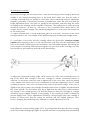
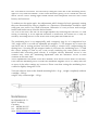
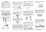
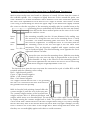
Mounting, Setup and Operations Instructions for brinkmann Tonearm 10.5
Mark a point on the tone arm board at a distance of exactly 243 mm from the center of
the turntable spindle. Use a compass to lightly draw two circles around this point, one
with a diameter of 20 mm and another with a diameter of 24 mm. Mark three points on
the outer circle equidistant to each other at 120° angles as shown. Drill out the 20 mm
circle using a woodcutting bit. Bevel the upper edge of the drilled hole slightly towards
the center so that the top plate of the mounting assembly with its rounded seam at the
mounting sleeve underneath will fit flush on the tone arm board.
Next drill out the three marked points on the outer circle for M3
size machine screws.
Insert
that
when
two
must
the mounting assembly into the 20 mm diameter hole making sure
the setscrew for fixing the tone arm in the mounting sleeve is easily
accessible. The slotted mounting plate and sleeve act like a clamp
the setscrew is tightened. To clamp the sleeve it is necessary that the
M3 mounting screws to the left and right of the slot allow some
movement. They are therefore supplied with copper washers and
not be fixed too tightly. The third mounting screw opposite the slot is
tightened without a washer.
Insert the tone arm into the mounting sleeve. With the arm sitting
firmly in the tone arm rest align it perpendicular to the front of
the turntable. As long as the setscrew in the mounting plate has
not been tightened the arm shaft in the sleeve can be moved up
and down using the height adjustment screw (10).
The internal wires from the tone arm must be connected to a pair of either RCA or XLR
terminals with the following color-coding:
Red = right channel positive
Green = right channel negative
White = left channel positive
Blue = left channel negative
The copper-colored fifth litz wire is for grounding
the arm. It is connected to the tone arm base and
the ground lead to the preamp.
With its beveled side pointing forward slide the
counter weight (2) onto the rear of the tone arm.
The counter weight consists of the beveled base
weight and two discs of different thickness and
weight, which move on a threaded shaft. The tracking force of the stylus can be adjusted
by simply moving the counter weight back or forth. The position of the counter weight
can be fixed with a small setscrew in the base weight. When using a very heavy cartridge
the two discs may have to be moved all the way back. With very light cartridges you may
have to remove one or the other of the weight discs. When using both discs make sure
that they are screwed tightly against each other to avoid resonance.
Mounting the Cartridge
Mount the cartridge into the head shell (1) with the mounting screws sitting in about the
middle of the slotted mounting holes in the head shell. Make sure that the sides of
cartridge and head shell run parallel to each other. We recommend using an adjustment
template, preferably a Dennesen Geometric Soundtracktor. Move the tone arm with the
height adjustment screw (10) until it is parallel to the turntable, and then align the stylus
according to the markings on the template (Geopoint). The tracking force at the stylus tip
should be between 1.8 and 2 g, not more or less if possible. More about that in the
chapter on the counter weight. The antiskating adjustment (7) at the tone arm should not
be set at this point.
To adjust azimuth take a strong magnifying glass (at least 10X) and look at the stylus
exactly from the front. The triangle of the diamond stylus tip should point straight down.
If a correction is necessary and the cartridge allows this procedure, exercise extreme
caution when inserting a piece of 0.8 mm diameter steel wire into the small lateral drill
hole in the round rod that presses the transducer onto the rubber damper. By turning the
rod in minute increments (without loosening the tiny set screws at the cartridge) you also
turn transducer and cantilever and with it the diamond tip.
To adjust the horizontal tracking angle (HTA) loosen one of the two mounting screws on
top of the head shell enough to turn the cartridge in minute increments inward or
outward. To check the result you must re-tighten the screw every time. Check by playing
a very familiar tune about one to two centimeters in from the beginning of the LP. Most
revealing would be a solo voice recorded in the center of the stereo image. If the voice is
slightly to the left of center the cartridge should be turned ever so slightly inwards towards
the center spindle. The increments may be so slight that the naked eye could not detect
any change. If the sound gets too soft and the image too hazy the cartridge as a whole
should be moved slightly forward. Consequently, if the sound gets brittle it should be
moved slightly back. These adjustments should be checked again after the cartridge is
broken in. Please note that the setting for antiskate will also slightly influence HTA.
Hence, changing the antiskating force amounts to a small adjustment in HTA.
Now adjust the vertical tracking angle (VTA). If you determine that after the correct setting
of the horizontal tracking angle highs are too dull and bass is too plump and uncontrolled
the VTA must be increased. You do that by raising the tone arm in the mounting sleeve,
again in very small increments. If the sound becomes glassy you’ve raised the arm too
much. At the correct setting highs sound natural and transparent and bass runs sound
bouncy and sonorous.
To underscore the point again: Any adjustments which change the basic geometric setting
that was determined by using a template or a Dennesen Soundtracktor should be done
with great care and in very small increments. Otherwise it is easy to loose track and get
further and further away from the desired results.
The rest on the tone arm lift can be height-adjusted by loosening the setscrew (11) and
raising or lowering it. If the upward extension is insufficient, the whole lift (5) may be
raised by loosening the hex screw at the front of the plate that holds the lift.
The antiskating force is set magnetically with a magnetic ring (6). It is magnetized at a
120° angle and it is set with an adjustable pin magnet (7). The magnets try to move the
arm back into its resting position and thus creating a counter force compensating the
skating force. Screwing the pin magnet further in increases the antiskating force. To find
the correct setting it is best to use a test record containing sine wave pulses or music
recorded with increasing peak velocity. If at higher velocity distortion occurs in one
channel only, move the antiskating adjustment until the distortion occurs in both
channels at the same time.
These adjustments only make sense after azimuth, HTA and VTA have been set correctly.
If the desired antiskating force exceeds the maximum magnetic force it is likely that one
or more of the other settings are incorrect. Please note that setting the antiskating force
could also slightly change the HTA.
Tonearm effective mass at the slotted mounting holes: 10 gr. , weight completely (without
cartridge) : 280 gr.
weight only counterweight : 150 gr.
brinkmann
Im Himmelreich 13
88147 Achberg
Germany
tel: 08380 981195
fax: 08380 981233
mail: [email protected]