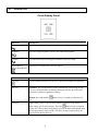
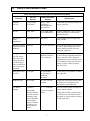
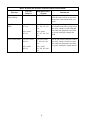
1
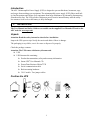
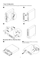
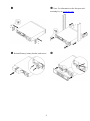
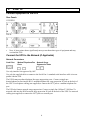
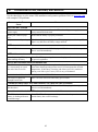
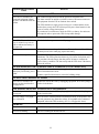
User Manual
English
APC Smart-UPS® SC
1000/1500 VA
110/120/230 Vac
2U Tower/Rack-Mount
Uninterruptible Power Supply
990-1851B, 05/2005
Introduction
The APC Uninterruptible Power Supply (UPS) is designed to prevent blackouts, brownouts, sags,
and surges from reaching your equipment. The uninterruptible power supply (UPS) filters small utility line fluctuations and isolates your equipment from large disturbances by internally disconnecting
from the utility line. The UPS provides continuous power from its internal battery until the utility
line returns to safe levels or the battery is fully discharged.
1:
INSTALLATION
The User Manual and Safety Guide are accessible on the supplied User Manuals CD and on the
APC web site, www.apc.com.
Unpack
Attention: Read the safety instruction sheet before installation.
Inspect the UPS upon receipt. Notify the carrier and dealer if there is damage.
The packaging is recyclable; save it for reuse or dispose of it properly.
Check the package contents:
Attention: The UPS comes with battery disconnected.
q
UPS
q
UPS literature kit containing:
q
Product documentation, safety and warranty information
q
Smart-UPS® User Manuals CD
q
PowerChute Business Edition® CD
q
Serial communication cable
q
Rack-mounting hardware
q
230 V models: Two jumper cables
Position the UPS
1
Tower Configuration
Note: Illustrations in this document may appear different than the actual hardware.
Œ
•
Ž
•
Mount the UPS in a Two-Post Rack
Œ
•
Remove battery bracket screws, battery
bracket, and battery.
2
Ž
• Note: For information on the four-post rackmounting kit, see www.apc.com.
• Reinstall battery, battery bracket, and screws.
3
‘
2:
START UP
Connect Equipment to the UPS
Rear Panels
110/120 V:
230 V:
•
Note: A laser printer draws significantly more power than other types of equipment and may
overload the UPS.
Connect the UPS to the Network (if Applicable)
Network Connectors
Serial Port
Modem/Telephone/Fax
Ports
Network Surge
Suppression Ports
Use only interface kits approved by APC.
Use only the supplied cable to connect to the Serial Port. A standard serial interface cable is incompatible with the UPS.
The UPS features modem/telephone/fax surge suppression ports. Connect a single modem/telephone/fax line into the RJ-11 modem/telephone/fax surge protection IN jack on the back of
the UPS. Use telephone cabling (not supplied) to connect the OUT jack to a modem/telephone/fax
port.
The UPS also features network surge suppression. Connect a single line 10 Base-T/ 100 Base-Tx
network cable into the RJ-45 network surge protection IN jack on the back of the UPS. Use network
cabling (not supplied) to connect the OUT jack to a network port.
4
Start the UPS
1.
Plug the UPS into a two-pole, three-wire, grounded receptacle only. Avoid using extension
cords. 110/120 V models: The power cord is attached to the UPS. The input plug is a NEMA 515P. 230 V models: The power cord is supplied in the UPS literature kit.
2.
110/120 V models: Check the site wiring fault LED
located on the rear panel. It will be illuminated if the UPS is plugged into an improperly wired utility power outlet (see Troubleshooting).
3.
Turn on all connected equipment. To use the UPS as a master on/off switch, be sure all connected equipment is on.
Press the button on the front panel to power the UPS.
4.
Note: The battery charges fully during the first four hours of normal operation. Do not expect
full battery run capability during this initial charge period. Refer to www.apc.com for on battery
runtimes.
5.
For optimal computer system protection, install PowerChute Business Edition management software to fully configure UPS shutdown and alarm settings.
5
3:
OPERATION
Front Display Panel
INDICATOR
DESCRIPTION
Online
The UPS is supplying utility power to the connected equipment.
On Battery
The UPS is supplying battery power to the connected equipment.
Overload
The connected loads are drawing more than the UPS power rating.
Replace Battery/
Battery Disconnected
The battery is disconnected or must be replaced.
FEATURE
FUNCTION
Power On
Press this button to turn the UPS on or off. (Read on for additional capabilities.)
Self-Test
Automatic: The UPS performs a self-test automatically when turned on, and
every two weeks thereafter (by default). During the self-test, the UPS briefly
operates the connected equipment on battery.
Manual: Press and hold the
test.
Cold Start
button for a few seconds to initiate the self-
Supply battery power to the UPS and connected equipment in the absence of
utility voltage (see Troubleshooting). Press the
button for one second and
release. The UPS will beep briefly and go quiet. Press and hold the button again,
but for approximately three seconds. The unit will emit a sustained beep. Release the button during this beep.
6
4:
USER CONFIGURABLE ITEMS
NOTE: SETTINGS ARE ADJUSTED THROUGH POWERCHUTE SOFTWARE
FUNCTION
FACTORY
DEFAULT
USER SELECTABLE
CHOICES
DESCRIPTION
Automatic
Self-Test
Every 14 days
(336 hours)
Every 7 days
(168 hours),
On Startup Only,
No Self-Test
Set the interval at which the UPS will
execute a self-test.
UPS ID
UPS_IDEN
Up to eight characters (alphanumeric)
Uniquely identify the UPS, (i.e. server
name or location) for network management purposes.
Date of Last
Battery
Replacement
Manufacture Date
mm/dd/yy
Reset this date when you replace the
battery module.
Minimum Capacity
Before Return from
Shutdown
0 percent
0, 15, 50, 90 percent
Specify the percentage to which batteries will be charged following a lowbattery shutdown before powering
connected equipment.
Voltage Sensitivity
High
High sensitivity,
Medium sensitivity,
Low sensitivity
Note: In situations of poor power quality, the UPS may frequently transfer to
battery operation. If the connected
equipment can operate normally under
such conditions, reduce the sensitivity
setting to conserve battery capacity
and service life.
Alarm Delay After
Line Fail
5 seconds
30 second delay,
At low battery
condition,
No alarm
Set the delay to avoid alarms for minor
power glitches.
Shutdown Delay
60 seconds
60, 180, 300, 600
seconds
Set the interval between the time when
the UPS receives a shutdown command and the actual shutdown.
Low Battery
Warning
2 minutes
2, 5, 7, 10 minutes
PowerChute
Business Edition
software provides
automatic, unattended shutdown
when approximately 2 minutes
of battery operated runtime remains.
(Times are approximate.)
The UPS will beep when 2 minutes of
battery runtime remains.
The UPS detects
and reacts to line
voltage distortions
by transferring to
battery operation to
protect connected
equipment.
7
Change the low battery warning interval setting to the time that the operating system or system software requires
to safely shut down.
NOTE: SETTINGS ARE ADJUSTED THROUGH POWERCHUTE SOFTWARE
FUNCTION
FACTORY
DEFAULT
USER SELECTABLE
CHOICES
DESCRIPTION
Synchronized
Turn-on Delay
0 seconds
0, 15, 45, 75 seconds
Specify the time the UPS will wait
after the return of utility power before
turn-on (to avoid branch circuit overload).
High Transfer
Point
110/120 V model:
127 Vac
110/120 V model:
127, 130, 133, 136
Vac
230 V model:
253 Vac
230 V model:
253, 257, 261, 265
Vac
Set the high transfer point higher to
avoid unnecessary battery usage when
the utility voltage is usually high and
the connected equipment is specified
to operate with input voltages this
high.
110/120 V model:
106 Vac
110/120 V model:
97, 100, 103, 106
Vac
230 V model:
208 Vac
230 V model:
196, 200, 204, 208
Vac
Low Transfer Point
8
Set the low transfer point lower when
the utility voltage is usually low and
the connected equipment is specified
to operate with input voltages this low.
5:
STORAGE AND MAINTENANCE
Storage
Store the UPS covered in a cool, dry location, with the battery fully charged.
At -15 to +30 °C (+5 to +86 °F), charge the UPS battery every six months.
At +30 to +45 °C (+86 to +113 °F), charge the UPS battery every three months.
Battery Replacement
The UPS battery life differs based on usage and environment. Consider replacing the battery every three years.
This UPS has an easy to replace, hot-swappable battery. Replacement is a safe procedure, isolated from electrical hazards. You may leave the UPS and connected equipment on during the replacement procedure. See your
dealer or contact APC (see Contact Information) for information on replacement batteries.
Note: Upon battery disconnection, equipment is not protected from power outages.
For the battery replacement procedure, refer to applicable steps in Mount the UPS in a Rack.
Be sure to deliver the spent battery to a recycling facility or ship it to APC in the replacement
battery packing material.
9
6:
TROUBLESHOOTING, SHIPPING, AND SERVICE
Use the chart below to solve minor UPS installation and operation problems. Refer to www.apc.com
with complex UPS problems.
PROBLEM AND/OR POSSIBLE
CAUSE
SOLUTION
UPS WILL NOT TURN ON
UPS not connected to utility
power supply.
Check that the power cord from the UPS to the utility power supply is securely connected at both ends.
Battery not connected properly.
Ensure that the battery is properly connected.
Very low or no utility voltage.
Check the utility power supply to the UPS by plugging in a table lamp. If the
light is very dim, have the utility voltage checked.
UPS WILL NOT TURN OFF
Internal UPS fault.
Do not attempt to use the UPS. Unplug the UPS, disconnect the battery, and
have it serviced immediately.
UPS BEEPS OCCASIONALLY
Normal operating UPS beeps
when running on battery.
None. The UPS is protecting the connected equipment from occasional utility power irregularities.
UPS IS NOT PROVIDING EXPECTED BACKUP TIME
The UPS battery is weak due
to a recent outage or is near
the end of the service life.
Charge the battery. Batteries require recharging after extended outages, and
wear faster when frequently put into service or when operated at elevated
temperatures. If the battery is near the end of the service life, consider replacing even if the replace battery LED is not yet illuminated.
ONLINE AND OVERLOAD LEDS ARE FLASHING ALTERNATELY
The UPS was shut down
through PowerChute.
None. The UPS will restart when utility power returns.
ONLINE AND ON-BATTERY LEDS ARE FLASHING, OR, OVERLOAD LED IS FLASHING
Internal UPS fault. The UPS
has shut down.
Do not attempt to use the UPS. Turn off the UPS, unplug the battery, and
have it serviced immediately.
ALL LEDS ARE OFF AND THE UPS IS PLUGGED INTO A WALL OUTLET
The UPS is shut down or the
battery is discharged from an
extended outage.
None. The UPS will return to normal operation when the power is restored
and the battery has a sufficient charge.
10
PROBLEM AND/OR POSSIBLE
CAUSE
SOLUTION
THE OVERLOAD LED IS ILLUMINATED AND THE UPS EMITS A SUSTAINED ALARM TONE
The UPS is overloaded. The
connected equipment is drawing more VA than the UPS can
sustain.
The connected equipment exceeds the specified “maximum load.”
The alarm remains on until the overload is removed. Disconnect nonessential equipment from the UPS to eliminate the overload.
The UPS continues to supply power as long as it is online and the circuit
breaker does not trip; the UPS will not provide power from batteries in the
event of a utility voltage interruption.
If a continuous overload occurs while the UPS is on battery, the unit turns
off output in order to protect the UPS from possible damage.
THE REPLACE BATTERY/BATTERY DISCONNECTED LED IS ILLUMINATED
This LED flashes and a short
beep is emitted every two seconds to indicate the battery is
disconnected.
Check that the battery connector is fully engaged.
Weak battery.
Allow the battery to recharge for 24 hours. Then, perform a self-test. If the
problem persists after recharging, replace the battery.
Failure of a battery self-test.
The UPS emits short beeps for one minute and the replace battery LED
illuminates. The UPS repeats the alarm every five hours. Perform the selftest procedure after the battery has charged for 24 hours to confirm the
replace battery condition. The alarm stops and the LED clears if the battery
passes the self-test.
THE SITE WIRING FAULT LED ON THE REAR PANEL IS ILLUMINATED (110/120 V MODEL ONLY)
The UPS is plugged into an
improperly wired utility power
outlet.
Wiring faults detected include missing ground, hot-neutral polarity reversal,
and overloaded neutral circuit.
Contact a qualified electrician to correct the building wiring.
THE INPUT CIRCUIT BREAKER HAS TRIPPED
The UPS is overloaded. The
plunger on the circuit breaker
has popped out.
Reduce the load on the UPS by unplugging equipment. Press in the plunger
on the circuit breaker.
UPS OPERATES ON BATTERY ALTHOUGH UTILITY VOLTAGE EXISTS
The UPS input circuit breaker
has tripped.
To reduce the load on the UPS, unplug equipment and press in the plunger
on the circuit breaker.
The line voltage is very high,
low or distorted.
Move the UPS to a different outlet on a different circuit, as inexpensive fuel
powered generators may distort the voltage. If acceptable to the connected
equipment, reduce the UPS sensitivity (see User Configurable Items).
ONLINE LED
There is no illumination.
The UPS is running on battery, or it must be turned on.
The LED is blinking.
The UPS is running an internal self-test.
11
Shipping and Service
Prepare the UPS for shipping:
Shutdown and disconnect any equipment attached to the UPS. Shut down the UPS, and disconnect
the UPS from the utility power outlet. Disconnect the battery.
If the UPS requires service do not return it to the dealer. Follow these steps:
1.
Review the problems discussed in Troubleshooting to eliminate common problems.
2.
If the problem persists, contact APC Customer Service through the APC web site, www.apc.com/support.
n
Note the model number of the UPS, the serial number, and the date purchased. If you call APC Customer Service, a technician will ask you to describe the problem and attempt to solve it over the phone.
If this is not possible, the technician will issue a Returned Material Authorization Number (RMA#).
n
If the UPS is under warranty, repairs are free.
3.
Pack the UPS in its original packaging. If this is not available, refer to www.apc.com/support for information about obtaining a new set.
n
Pack the UPS properly to avoid damage in transit. Never use Styrofoam beads for packaging. Damage
sustained in transit is not covered under warranty.
n
Always DISCONNECT THE BATTERY before shipping in compliance with U.S. Department of
Transportation (DOT), and IATA regulations. The battery module(s) may remain in the UPS; it
does not have to be removed.
4.
Mark the RMA# on the outside of the package.
5.
Return the UPS by insured, prepaid carrier to the address given to you by Customer Service.
Contact Information
U.S. Customers - Refer to www.apc.com/support.
International Customers - Refer to www.apc.com, select the appropriate country from the country selection
field, and select the Support tab at the top of the web page.
12
7:
REGULATORY AND WARRANTY INFORMATION
110/120 V models
This equipment has been tested and found to comply with the limits for a Class A digital device, pursuant to part 15 of the FCC Rules. These limits are designed to provide reasonable protection against
harmful interference when the equipment is operated in a commercial environment. This equipment
generates, uses, and can radiate radio frequency energy and, if not installed and used in accordance
with the instruction manual, may cause harmful interference to radio communications. Operation of
this equipment in a residential area is likely to cause harmful interference in which case the user will
be required to correct the interference at his/her own expense.
Shielded signal cables must be used with this product to ensure compliance with the Class A FCC
limits.
230 V models
This is a Class A product. In a domestic environment this product may cause radio interference, in
which case the user may be required to take corrective actions.
13
Limited Warranty
American Power Conversion (APC) warrants its products to be free from defects in materials and workmanship
for a period of two years from the date of purchase. Its obligation under this warranty is limited to repairing or
replacing, at its own sole option, any such defective products. To obtain service under warranty you must obtain
a Returned Material Authorization (RMA) number from customer support. Products must be returned with
transportation charges prepaid and must be accompanied by a brief description of the problem encountered and
proof of date and place of purchase. This warranty does not apply to equipment that has been damaged by accident, negligence, or misapplication or has been altered or modified in any way. This warranty applies only to the
original purchaser who must have properly registered the product within 10 days of purchase.
EXCEPT AS PROVIDED HEREIN, AMERICAN POWER CONVERSION MAKES NO WARRANTIES,
EXPRESSED OR IMPLIED, INCLUDING WARRANTIES OF MERCHANTABILITY AND FITNESS FOR
A PARTICULAR PURPOSE. Some states do not permit limitation or exclusion of implied warranties; therefore, the aforesaid limitation(s) or exclusion(s) may not apply to the purchaser.
EXCEPT AS PROVIDED ABOVE, IN NO EVENT WILL APC BE LIABLE FOR DIRECT, INDIRECT,
SPECIAL, INCIDENTAL, OR CONSEQUENTIAL DAMAGES ARISING OUT OF THE USE OF THIS
PRODUCT, EVEN IF ADVISED OF THE POSSIBILITY OF SUCH DAMAGE. Specifically, APC is not liable for any costs, such as lost profits or revenue, loss of equipment, loss of use of equipment, loss of software,
loss of data, costs of substitutes, claims by third parties, or otherwise.
Entire contents copyright 2005 by American Power Conversion Corporation. All rights reserved.
Reproduction in whole or in part without permission is prohibited.
APC, the APC logo, Smart-UPS, and PowerChute are registered trademarks of American Power
Conversion Corporation. All other trademarks are the property of their respective owners.
14