1
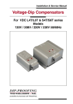
Instruction Manual for Motion Checker MCH-5
Warning
Read this manual before use for safe operation.
After reading, please keep this manual where you can refer to it anytime.
1. Safety precautions
● Do not use in damp areas or areas where the temperature is always high.
● If an electric current is supplied continuously to the motor, the motor will get hot.
Be careful not to get burned or to distort resins.
● To avoid electric shock hazards, do not disassemble or modify the device.
● A malfunction or a failure may occur on electrical products.
When using the product, caution must be taken not to damage human life, body or property.
● If a foreign matter gets into the body case, pull out the power cord first and remove the foreign matter.
● Use a motor that is within the rated range. Otherwise, a fuse may be blown or the motor may overheat,
causing a burn.
● Tighten the screw on a lead wire to the terminal block so that the stripped portions of adjoining lead wires
do not come in contact with each other. If they come in contact, it may cause a failure.
● If an abnormality (unusual noise, foreign odor or smoking) occurs, pull out the power cord.
● Do not touch the AC adapter with a wet hand. It may cause electric shock hazards.
● Do not cover the machine body or the AC adapter with a blanket, etc.
It may cause a deformation of the case or a fire.
2. Check the contents
Check the contents of the product. Each one of the following parts is included:
● MCH main body
● AC adapter (DC12V, 2A)
● Power cord (2-prong plug for MCH-5U/B-J, 3-prong plug for MCH-5 U/B-E)
● Stepping motor (PFCU25 type for MCH-5U, PFCU20 type for MCH-5B)
● Motor connecting cable (5 lead wires for MCH-5U, 4 lead wires for MCH-5B)
● Flat head screwdriver
● Instruction Manual (English and Japanese)
3. Names of portions
4
3
2
1
7
1
2
3
4
5
PJ1 (AC adaptor connecting plug jack)
MOTOR (Motor connecting terminal)
OUTPUT (External output terminal)
INPUT (External input terminal )
Main body mounting hole, use of M4 tapping screw,
effective depth 10mm
6 ORG (origin) display.
7 Counter display
8 Panel switches
6
MCH-5
12-24VDC
ENABLE
10
INPUT
1
6 OUTPUT 1
6 MOTOR 1
SETUP
Std
LSPD
L
PULSE
H
LSPD
L
ACC/DEC
t
SP
HSPD
ACC/
DEC
WAIT
H
PATTERN
ORG
CW
n
n
n
n
n
HSPD
n
CYCLE
CW/CCW
PAUSE
ORG
ENABLE
START
RESET
MODE
STOP
CHOICE
EXCITATION
ORG
MENU
Pr*
(CW/CCW)
C
Pn/Et ORG
FULL/
HALF
Or
P
t
E
Or*
: MENU
: SHIFT + MENU
SET : MODE OR n-KEY
SHIFT
PROGRAM:START
INCHING:SHIFT+START
JOG
:SHIFT+START(1sec)
8
5
4. Product Specifications
Electrical
Specifications
Input voltage
12Vdc (2A) to 24Vdc (1A), 24Watt or less
(Power is supplied by AC adapter)
Protective fuse
2A fuse is mounted on the line of the motor power
Output
current
MCH-5U
Rating 250mA per phase (NP-2671 Drive IC)
MCH-5B
Rating 400mA per phase (NP-3775 Drive IC)
Driving
system
MCH-5U
Unipolar constant voltage
MCH-5B
Bipolar constant voltage
Excitation mode
Full-step (2-2 phase excitation) or half-step (1-2 phase excitation)
Setting change
100,000 times (EEPROM used)
Operating temperature
Environmental
Operating humidity
Specifications
Storage temperature
External dimensions
0 to 80% RH(No condensation)
-10 to 70℃
122mm(L)×80mm(W)×27mm(H)
Mass (main body)
140g or less
Environmental quality
RoHS compliance
Cooling method
Air cooling without blower
Accessories MCH-5U
Other
Specifications
0 to 40℃
MCH-5B
MCH-5U/B
-J
MCH-5U/B
-E
Motor: PFCU25-24C1G(1/20)-01
Rated 12V, coil resistance 120O/phase
0.75deg/step (at 2-2 phase excitation)
Motor: PFCU20-40S4GA2(1/10)-10
Rated 12V, coil resistance 160O/phase
0.9deg/step (at 2-2 phase excitation)
AC Power cord: Domestic specification
AC Power cord: Overseas (USA) specification
AC adaptor: 100 to 240VAC input / 12VDC, 2A output)
Plug: Inside diameter of φ2.1mm, Outside diameter of φ5.5mm,
Center (+) pole
● Input voltage is used for driving motor.
Use the power supply voltage corresponding to the motor rating.
● If a motor other than the supplied motor is used, use the motor within the rating
range of the motor and the motion checker.
5. Mounting/Wiring procedure
1) Connect a motor connecting cable to the stepping motor.
2) Connect the lead wires of the motor to the MCH main body as indicated in Table 1. Retain the lead wires
with a flat head screwdriver so that adjoining lead wires don’t come into contact with each other.
3) The MCH-5 has external input and output functions. Connect wires according to Tables 2 and 3 as needed.
4) Connect the power cord to the AC adapter and the plug to the jack PJ1 on the MCH main body.
5) The main body can be mounted on the chassis by using the mounting hole at the back of the body as needed.
The mounting/wiring procedure is completed.
<Precautions on mounting/wiring>
● Before connecting or removing the lead wires of motor, turn off the ENABLE switch.
● While the power is ON, power voltage is being supplied from the OUTPUT terminal. Before wiring,
pull out the power cord from the outlet.
● The depth of M4 tapping hole for mounting should be within 10mm
<Table 1> MOTOR terminal (Standard colors of lead wires for NPM Motor)
CN1
6
5
4
3
2
4φ
2φ
3φ
1φ
COM
Unipolar U spec (MCH-5U)
Yellow
Orange
Brown
Black
Red
B
B
A
A
Bipolar B spec (MCH-5B)
Yellow
Red
Orange
Brown
<Table 2> OUTPUT terminal (Open collector output, 26V or less, 30mA or less)
CN2
6
5
4
3
2
1
ORG
BSY
+5V
-PO
+PO
GND
1
COM
(Red)
-
<Table 3> INPUT terminal (Contact input with GND line)
CN3
10
9
8
7
6
5
4
ORG
-SD
+SD
-EL
+EL
ORG-RV
ENB
3
CW/CCW
(PAUSE)
2
1
ST/SP
GND
<Explanation of signs in Tables 2 and 3>
±PO
: Pulse output terminal.
Pulse is output and it can be connected to an external driver.
BSY
: External output terminal for signal during operation
H= Under stop / L= Under operation
ORG
: Origin signal. If external input ORG is received, an external output ORG (L) will be sent.
ST/SP
: External input terminal for start/stop.
H= Stop / Leg = Start
CW/CCW : External input terminal for switching the rotating direction.
H= CW / L= CCW
(PAUSE)
Pauses or restarts a program during operation.
Leg = pause, restart
ENB
: External input terminal for ENABLE.
H= Disenable / L= Enable
ORG-RV
: External input terminal for start/stop of zero return operation.
H= Stop / Leg= Return start
±EL
: Input terminal for end limit signal.
H= Normal / L= EL detection
±SD
: Input terminal for slow down signal.
H= Normal / L= Low speed
(Leg indicates the down edge of signal.)
6. Explanation of operation
1) Turning on the power
Insert the power cord to the outlet. “.000000” will be displayed.
2) Excitation
Press the “ENABLE” switch, and “  ̄ ” will comes on in the seventh digit on the indicator, and electric
current is supplied to the motor.
3) Setting rotation direction
“.” in the seventh digit on the display will come on (indicates clockwise rotation) or go off (indicates
counterclockwise rotation) alternately by pressing the CW/CCW switch. The CW/CCW switch specifies the
rotation direction during inching and jog operations and the operation when “2 Origin sensor valid” is set
in ⑭ ORG-REV in Section 7. Setting.
4) Inching and jog operations
The inching operation is performed when the START switch is pressed (for one second or less) with
SHIFT being pressed while “  ̄ ” is lit.
If the START switch is pressed for one or more second while keeping SHIFT pressed, jogging operation
will start after inching operation.
The motor stops when the STOP switch is pressed during the jog operation, and the counter also stops.
When not used, turn off the ENABLE switch to prevent the motor from overheating.
5) Starting the program
The program starts operation when the START switch is pressed while “  ̄ ” is lit.
The program stops when it is executed the number of times set in ⑪ Number of program repetition times
in Section 7. Setting.
The motor and the counter stop when the STOP switch is pressed during program operation.
6) PAUSE function
When the PAUSE switch is pressed during program operation, the program stops temporarily on completion of
a step under execution.
(When a value other than “0” is set for step under execution in ⑧ Stop time period in Section 7. Setting.)
A program restarts execution from the subsequent step by pressing the PAUSE switch in the state where
the program temporarily stopped.
7) Switching display during program operation
When the SHIFT switch is pressed during program operation, the display switches from “Counter display”
to “Step No. under execution”, and “Current number of repetition times.”
The display returns to “Counter display” automatically when the motor stops.
8) Resetting the counter display
The counter will be cleared when the RESET switch is pressed while the motor is stopped.
9) ORG Switch
When the ORG switch is pressed, the homing operation set in ⑭ ORG-REV in 7. Setting is executed.
When the “2 Homing sensor valid” is set, specify the rotation direction with the CW/CCW switch.
10) Setting mode
Press the MENU switch to shift from the counter display screen to the setting mode for changing settings
such as speed increase/decrease time, number of repetition times, and exciting system.
In the setting mode, pressing the MENU switch moves to the next item and pressing the MENU switch
together with the SHIFT switch returns to the previous item.
However, in the Std screen, the display does not return to the main screen but shifts to the Or-1 screen.
Press the SHIFT switch together with MODE switch to return from the Std screen to the main screen and
return to the counter display screen.
Numeric values are set by pressing the panel switch “n” to count up and pressing the “n” switch together
with the SHIFT switch to counts down. Use the MODE switch for the other settings.
(See Section 7. Setting for the detailed setting flow.)
11) Initializing the set values
Pressing the SHIFT switch together with the MENU switch for three or more seconds while the motor is
stopped will restore all the set items to their initial states.
7. Setting
1
.000000
Pr1…6
MENU
2
Std
MODE
Pr1
CW/
CCW
MENU
3
5
6
7
CW/CCW
H000600
<FL
HSPD
t000100
4
13
14
MENU
CW/CCW
SP−1
C000001
Pn
CHOICE
2−2
EXCITATION
P001000
P001000
PULSE
5
L100010
=0
LSPD
L600010
=0
LSPD
6
H100600
<FL
HSPD
H600600
<FL
HSPD
ACC/DEC
CYCLE
12
CW/
CCW
PULSE
PATTERN
11
MENU
MODE
Pr6
L000010
=0
LSPD
>1600
10
MODE
7
t100100
>1600
8
ACC/DEC
E101000
WAIT
9
Or1−0
ORG(Or1)
Initial value: Pn
Setting: Pn
Validates the panel switches mounted on the main unit.
Et1
Validates the INPUT terminals ST/SP, CW/CCW, ENB, and ORG-REV become effective (Latching).
Et2
Validates the INPUT terminals ST/SP, CW/CCW, ENB, and ORG-REV become (Momentary).
●When the external input Et1 or Et2 is set, the PAUSE switch enters momentary operation.
⑬ Excitation mode (FULL/HALF)
Use the MODE switch to set either Full step or Half step.
Initial value: 2-2 (Full step)
Setting:
2-2 (Full step)
1-2 (Half step)
⑭ ORG-REV (ORG switch)
Set the homing method with either the ORG switch mounted on the panel or the INPUT terminal
ORG-REV. (Switching between panel operation and external input ⑫ is set by the MODE switch.)
Initial value: Or -1
Setting:
1
Default homing *1
2
Home sensor valid
*1
t600100
>1600
ACC/DEC
E601000
WAIT
Or6−0
ORG(Or6)
Or −1
ORG(Or)
Saving set values
① Main display (current counter display)
② Step selection screen
Select either the basic common settings (Std) such as the number of repetition times of program operation,
the exciting system, and the settings for each steps (Pr*) with the MODE switch, and press the MENU
switch to set the common items or the items for each step.
Display:
Std or Pr1 to 6
③ Direction setting
Select the rotation direction in each step on the step selection screen with the CW/CCW switch.
(The display is made by the highest 7-segment dot. CW: lit, CCW: unlit).
Initial value:
“.” dot lit (CW)
④ Preset
Set the number of moving pulses for positioning operation with the value n in each digit switch.
Initial value:
P001000
Setting range: 0 to 999999pulse
●When the preset value is set to be “0” to Pr2 through Pr6, the execution will be performed up to the step
immediately preceding that step. At this time, if “0 Origin sensor invalid” is not set in ⑨ ORG-REV,
the setting of ⑨ ORG-REV will be given priority.
⑤ Low-speed operation (LSPD)
Set the rotation speed (pulse/sec) at low-speed rotation with the value n in each digit switch.
Initial value: L*00010 (* is the step number)
Setting range: 1 to 999pps
⑥ High-speed operation (HSPD)
Set the rotation speed (pulse/sec) at high-speed rotation with the value n in each digit switch.
Initial value: H*00600 (* is the step number)
Setting range: 1 to 7999pps
⑦ Acceleration/deceleration time (ACC/DEC)
Set the speed increase/decrease time (100 to 1600msec) between low speed and high speed with the value n.
Note that the setting will be changed automatically if the value exceeds the allowable setting range.
Initial value: t*00100 (* is the step number)
Setting range: 100 to 1600msec (in 100msec units)
⑧ Stop time (WAIT)
Set the stop time after the end of each step during program operation with the value n in each digit switch.
Initial value: E*01000 (* is the step number)
Setting range: 100 to 4900ms (in 100ms units)
● When the value is set to be 0, a program temporarily stops its operation at the end of each step.
Press the PAUSE switch during temporary stop to restart a program from the next step.
⑨ ORG-REV (with Program mode)
When ORG-REV is set with the MODE switch, zero return operation is executed during program operation.
Setting: 0 Home sensor invalid
1 Default the homing *1
2 Home sensor valid
3 Uses +EL as home sensor
4 Uses –EL as home sensor
●When any one of 2 through 4 is set, it is necessary to specify the rotation direction by setting CW/CCW.
If the motor rotates to a direction where there is no origin sensor, the motor will either be stopped by
the EL sensor or continues to rotate. Therefore, this setting should be made with care.
●Program operation can be continued without emergency stop even when the +EL sensor and +EL
sensor are detected when 3 and 4 are set, respectively.
In this case, it is necessary to make the motor rotate to an opposite direction detected by EL in the
next step. (counterclockwise when 3 is set and clockwise when 4 is set)
●The setting of ⑨ ORG-REV is given priority over the zero setting of ④ Preset.
⑩ Setting low speed and increase/decrease in speed
Select SP1 or SP2 with the MODE switch.
Initial value: SP1
Setting:
SP1 Low-speed setting of jog or homing operation with the ORG switch
SP2 High-speed setting of jog and homing operation with the ORG switch
⑪ Number of program repetition times
Set the number of times program operation is repeated with the value n in each digit switch.
Initial value: C000001
Setting range: 0 to 9999 (0 sets infinite number of times and 1 sets single operation.)
⑫ Switching between panel operation and external input
Use the MODE switch to set either panel operation or external input.
When “1 Default zero return” is set by ORG-REV in ⑨ or ⑭, high-speed movement is made to the
counterclockwise direction until the first –EL signal is input. If –SD is input during the motion, the speed
will be decreased.
After stop by –EL input, the movement switches to the clockwise direction and stops when the origin signal
ORG is input.
Other Functions
1) Canceling the settings
The current setting is canceled by pressing the MENU switch for three or more seconds in the setting mode
② through ⑭, and the display returns to the main screen ① with the values set before entering the setting
mode.
2) Initializing the set values
To return all the set values to their initial states, press the SHIFT switch together with the MENU switch for
three or more seconds in ① main display.
<Precautions on operation>
● When “Err” is displayed, the set values may not be written or read normally.
● Do not turn on the power immediately after turning it off.
This may cause errors in saved data or may cause malfunction.
● If the power is turned off while returning from the setting mode to the main screen, the data will not be
saved normally.
● Unless the set value of operation pattern becomes FL<FH, the next menu cannot be operated.
● The counter display during continuous operation returns to 0 when overflow occurred. If overflow
occurred 16 times, the display becomes inaccurate.
● If the moving amount < pulse required for speed up/down is set, the speed will decrease before reaching
the high speed setting.
● Even if the time of speed-up/down “t” is within the setting range, “1023” will be automatically set
when the rate set value exceeds 1023 (3FF hex).
(HSPD set value - LSPD set value) × Rate set value
Acceleration/deceleration time [sec]=
4915200[Hz]
●
Only with acceleration/deceleration operation will work when it is operated by the program mode.
8. Torque curve of the supplied motor (Pull-out torque, Reference value)
Motor A
Model: PFCU25-24C1G (1/20)-01
Drive system: Unipolar constant voltage drive
Drive circuit: MCH-5U
(Drive IC: NP2671)
Gear strength (Ordinary): 20mN・m
Motor B
Model: PFCU20-40S4GA (1/10)-10
Drive system: Bipolar constant voltage drive
Drive circuit: MCH-5B
(Drive IC: NP3775)
Gear strength (Ordinary): 10mN・m
9. Troubleshooting
● Power doesn’t turn on.
- Has the power cord connected to the AC adapter fully and make sure the plug is connected to body fully?
● Motor doesn’t run.
- When using MCH-5, check that the ENABLE “ ̄”lights up.
- Has the sheath of cable been caught in the connecting portion of the motor lead wire and the terminal block?
Check that the core of the cable has been inserted properly.
- Motor has the characteristic that a limit of high-speed (Max. pull-out rate).
Has the set value exceeded the limit of the motor specification?
On MCH-5, decrease the set value of HSPD.
- Has a bipolar motor been connected to the MCH-5U as unipolar type?
● Abnormal movement.
- Has the motor been connected according to Table 1?
- Is a different manufacturer’s motor used? The terminals of different manufacturer’s motor may be
different from those of Table 1. Check the motor spec.
- Has the sheath of cable been caught in the connecting portion of the motor lead wire and the terminal
block? Check that the core of the cable has been inserted properly.
10. Guarantee
The guarantee term is one year from the purchase date.
If a failure due to defect caused in manufacturing occurs during the guarantee term, we will repair or exchange
this product at no charge.
11. Contact
For technical inquiries or questions on this product, contact the following address:
<Asia/Europe>
Nippon Pulse Motor Co., Ltd. Asia/Europe Sales Group
2-16-13 Hongo, Bunkyo-ku, Tokyo 113-0033, Japan
TEL: 81-3-3813-8841
Web:http://www.pulsemotor.com
E-mail: [email protected]
<North/South America>
Nippon Pulse America, Inc.
4 Corporate Drive, Radford, VA 24141 U.S.A.
TEL: 1-540-633-1677
Web:http://www.nipponpulse.com
E-mail: [email protected]
Specifications of various models can be downloaded at our website.
No.YA7101-E/0