1
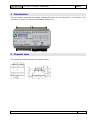
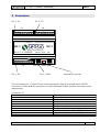
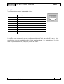
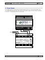
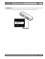
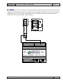
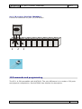
Title: Page 1 of 15 Edition 2 SC-1 User Manual Document SC-1_Ver_1-4_User_Manual.doc Date 11.02.2013 Author Tore Revised Approved SC-1 User Manual Contents 1 2 3 3.1.1 3.1.2 4 5 6 7 7.1 8 9 9.1 9.1.1 9.1.2 10 11 Introduction .............................................................................................. 2 Physical view............................................................................................. 2 Connectors ................................................................................................ 3 Comm. connector ................................................................................... 4 Ethernet connector ................................................................................. 5 Power Supply ............................................................................................ 6 Network .................................................................................................... 7 Temperature probes .................................................................................. 8 Potential free contact inputs ..................................................................... 9 Pulse power meters .............................................................................. 10 Relay ....................................................................................................... 11 Connecting IR sensors and emitter ......................................................... 12 IR sensor, standard type with positive going pulse .................................... 12 IR emitter............................................................................................ 13 IR receiver Everlight IRM8601S .............................................................. 14 Commands and programming ................................................................. 14 Specifications .......................................................................................... 15 SENSIO AS • MALERHAUGVN 25 • 0661 OSLO, www.sensio.no 1 Title: SC-1 User Manual Page 2 of 15 Edition 2 1 Introduction This document describes the usage and specifications for the Sensio SC-1 Controller. The controller is built in a DN rail mountable plastic box. 2 Physical view The physical measurements are shown below. felles:Produkt:SC-1:SC-1_Ver_1-4_User_Manual.doc 2 Title: Page 3 of 15 Edition 2 SC-1 User Manual 3 Connectors Pin 1, C1 Pin 1, C2 C1 C2 T1 T2 T3 T4 T5 T6GaBzGn D1D2D3D4R1R2R3R4V+ SC-1 SC-1 P5Gn In Io Ii V+RpRmGn C3 Pin 1, C3 RS232 Reset RS232 Eth Reset Eth Pin 1, RJ45 Internal IR receiver The connectors C1, C2 and C3 are screw connectors with 9 terminals each. RS232 connector is RJ45 and Eth connector is RJ45. Between RS232 and Eth connector is the reset switch. Connector C1 Pin 1 2 3 4 5 6 7 8 9 felles:Produkt:SC-1:SC-1_Ver_1-4_User_Manual.doc Description Temperature 1 Temperature 2 Temperature 3 Temperature 4 Temperature 5 Temperature 6 Analog ground (common NTC) Buzzer out (active pull to GND) GND 3 Title: Page 4 of 15 Edition 2 SC-1 User Manual Connector C2 Pin 1 2 3 4 5 6 7 8 9 Description Digital input 1 (internal pull up) Digital input 2 (internal pull up) Digital input 3 (internal pull up) Digital input 4 (internal pull up) Relay driver 1 (active pull to GND) Relay driver 2 (active pull to GND) Relay driver 3 (active pull to GND) Relay driver 4 (active pull to GND) +12V supply voltage Connector C3 Pin 1 2 3 4 5 6 7 8 9 Description +5V regulated out (25 mA) GND IR neg. input, IR channel 2 in SW IR output IR input standard, IR channel 1 in SW +12V supply voltage RS485 positive RS485 negative GND Note: The internal IR receiver is channel 3 in SW. 3.1.1 Comm. connector The communication connector has pins for RS232 port A and B. Pin Description 1 AUX input (do not connect) 2 AUX output (do not connect) 3 +12V supply voltage 4 GND 5 Port B RX 6 Port B TX 7 Port A RX 8 Port A TX felles:Produkt:SC-1:SC-1_Ver_1-4_User_Manual.doc 4 Title: SC-1 User Manual Page 5 of 15 Edition 2 3.1.2 Ethernet connector The Ethernet connector is standard 4 wire. Pin Description 1 TX+ 2 TX- 3 RX+ 4 GND 5 GND 6 RX- 7 +12V 8 +12V Note! The power connections here are for supplying +12V through the Ethernet cable as an option. This is not PoE, i.e. not compatible with IEEE 802.3af (which is 48V). The connections are not compatible with certain Apple products, i.e. Apple AirPort, in which case only connections to pins 1,2,3,6 must be used. felles:Produkt:SC-1:SC-1_Ver_1-4_User_Manual.doc 5 Title: Page 6 of 15 Edition 2 SC-1 User Manual 4 Power Supply The power supply is connected to screw terminals C3 Pin 6 (+12V) and 9 (GND). The SC-1 itself will draw less than 150 mA from the power supply, but each relay coil driven by the SC-1 may add 20-200 mA to the total. T1 T2 T3 T4 T5 T6GaBzGn D1D2D3D4R1R2R3R4V+ SC-1 SC-1 P5Gn In Io Ii V+RpRmGn 12V RS232 12V Eth GND 220V felles:Produkt:SC-1:SC-1_Ver_1-4_User_Manual.doc 6 Title: SC-1 User Manual Page 7 of 15 Edition 2 5 Network The SC-1 is connected to a switch/router with a normal Ethernet patch-kabel. T1 T2 T3 T4 T5 T6GaBzGn D1D2D3D4R1R2R3R4V+ SC-1 P5Gn In Io Ii V+RpRmGn SC-1 RS232 12V felles:Produkt:SC-1:SC-1_Ver_1-4_User_Manual.doc Eth 7 Title: Page 8 of 15 Edition 2 SC-1 User Manual 6 Temperature probes Temperature probes (Sensio type) are connected to SC-1 between terminals T1-T6 (C1 Pin 1-6) and analog ground (C1 Pin 7). Svart Hvit T1 T2 T3 T4 T5 T6GaBzGn D1D2D3D4R1R2R3R4V+ SC-1 P5Gn In Io Ii V+RpRmGn SC-1 RS232 12V Eth The Temperature probes are of type NTC with nominal value of 50 KOhm and Beta value of 3950. The probes are internally connected in a bridge with 47Kohm as the other leg. Different NTC values are possible, but should not be far away from the default values to maintain the accuracy. The Telnet commands for changing the NTC configuration resistance and Beta is “ntcr” and “ntck”, see FW manual. felles:Produkt:SC-1:SC-1_Ver_1-4_User_Manual.doc 8 Title: Page 9 of 15 Edition 2 SC-1 User Manual 7 Potential free contact inputs Potential free contacts are connected to the SC-1 between terminals D1-D4 (C2 Pin 1-4) and digital ground Gn (C1 Pin 9). The terminal are internally connected to +5V with a 10 KOhm resistor (0.5 mA contact current). The input terminals are voltage limited through a 10KOhm resistor (clamped to GND or +5Volt with zenerdiode). This means the input terminals may be connected to a voltage source, and the tripping point will be around 2 Volt. T1 T2 T3 T4 T5 T6GaBzGn D1D2D3D4R1R2R3R4V+ SC-1 P5Gn In Io Ii V+RpRmGn felles:Produkt:SC-1:SC-1_Ver_1-4_User_Manual.doc SC-1 RS232 12V Eth 9 Title: Page 10 of 15 Edition 2 SC-1 User Manual 7.1 Pulse power meters Power meters with pulse output (S0) are also connected to the D1-D4 terminals. The pulse outputs are normally opto isolator outputs, and the positive side (collector) is connected to D1-D4 and the negative side (emitter) is connected to ground. Shown connection to type M1DC-23005-1: T1 T2 T3 T4 T5 T6GaBzGn D1D2D3D4R1R2R3R4V+ SC-1 P5Gn In Io Ii V+RpRmGn felles:Produkt:SC-1:SC-1_Ver_1-4_User_Manual.doc SC-1 RS232 12V Eth 10 Title: Page 11 of 15 Edition 2 SC-1 User Manual 8 Relay Relays are connected to the SC-1 between the terminals R1-R4 (C2 Pin 5-8) and +12Volt supply (C2 Pin 9). The R1-R4 terminals are open collector pull down transistor drivers with a 300 mA current limiter (PTC resistor). 4 Relè 1 2 + - T1 T2 T3 T4 T5 T6GaBzGn D1D2D3D4R1R2R3R4V+ SC-1 P5Gn In Io Ii V+RpRmGn felles:Produkt:SC-1:SC-1_Ver_1-4_User_Manual.doc SC-1 RS232 12V Eth 11 Title: Page 12 of 15 Edition 2 SC-1 User Manual 9 Connecting IR sensors and emitter 9.1 IR sensor, standard type with positive going pulse Connect to C3, Pin 2,5,6 with GND and +voltage wires as shown. GND + T1 T2 T3 T4 T5 T6GaBzGn D1D2D3D4R1R2R3R4V+ SC-1 P5Gn In Io Ii V+RpRmGn SC-1 RS232 12V Eth signal felles:Produkt:SC-1:SC-1_Ver_1-4_User_Manual.doc 12 Title: SC-1 User Manual Page 13 of 15 Edition 2 9.1.1 IR emitter Connect to C3, Pin 2,4 with positive on Pin 4 and negative on GND (channel 0) or R1-4 (channel 1-4). T1 T2 T3 T4 T5 T6GaBzGn D1D2D3D4R1R2R3R4V+ SC-1 SC-1 P5Gn In Io Ii V+RpRmGn RS232 12V Eth T1 T2 T3 T4 T5 T6GaBzGn D1D2D3D4R1R2R3R4V+ SC-1 P5Gn In Io Ii V+RpRmGn SC-1 RS232 12V Eth felles:Produkt:SC-1:SC-1_Ver_1-4_User_Manual.doc 13 Title: SC-1 User Manual Page 14 of 15 Edition 2 9.1.2 IR receiver Everlight IRM8601S Connect to connector C3, Pin 1,2,3 as shown. 1 2 3 10 Commands and programming The SC-1 is SW compatible with AHC3000. The only difference is in number of IO ports and physical configuration. See AHC3000 User Manual for description. felles:Produkt:SC-1:SC-1_Ver_1-4_User_Manual.doc 14 Title: SC-1 User Manual Page 15 of 15 Edition 2 11 Specifications Ø Ø Ø Ø Ø Ø Ø Ø Ø Ø Ø Ø Ø DIN rail, 6 modules 12VDC input voltage – 10V-15V (2 W) Ethernet interface 1 (4) IR transmitter driver (variable frequency) 4 relay coil open collector driver outputs (12 V relays), current limited 4 NO/NC switch inputs (pull up 3.3V) 6 channel temperature measurement input (NTC) Internal temperature sensor (channel 7) 2 serial communication channels RS232 IR code receiver (optical) 2 IR code receiver inputs (wire-or’ed), one positive going pulse and one negative going pulse Internal battery backup for storage of state information during power loss Operating temperature range is 0-50 deg. Celsius. felles:Produkt:SC-1:SC-1_Ver_1-4_User_Manual.doc 15