1
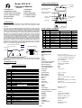
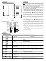
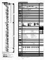
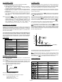
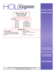
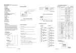
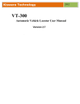
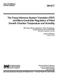
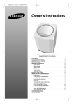
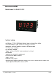
User's Manual
FDC-8130
Self-Tune Fuzzy / PID
Process Temperature Controller
3. FRONT PANEL DESCRIPTION
Model: FDC-8130
Instruction Manual
°F Indicator
CONTENTS
1. INTRODUCTION
7. CALIBRATION
2. NUMBERING SYSTEM
8. OPERATION
3. FRONT PANEL DESCRIPTION
9. ERROR MESSAGES
4. INPUT RANGE & ACCURACY
10. COMMON FAILURES
5. SPECIFICATIONS
11. T/C COLOR CODES
C
F
PV
°C Indicator
Process Value Display
( 0.4" red LED)
SV
Setpoint Value Display
( 0.3" green LED)
OUT1 OUT2
ALM1 ALM2
Control Outputs
Alarm Outputs
Scroll Key
Down Key
6. INSTALLATION
AT
Return Key
Up Key
1. INTRODUCTION
This manual contains information for the installation and operation of the
Future Design model FDC-8130 Fuzzy Logic micro-processor based
controller.
The Fuzzy Logic is an essential feature of this versatile controller. Although
PID control has been widely accepted by industries, yet it is difficult for PID
control to work with some sophistic systems efficiently, for examples
systems of second order, long time-lag, various setpoints, various loads,
etc. Because of disadvantage of controlling principles and fixed values of
PID control, it is inefficient to control the systems with plenty of varieties,
and the result is obviously frustrating for some systems. The Fuzzy Logic
control can overcome the disadvantage of PID control, it controls the system
in a efficient way by experiences it had before. The function of Fuzzy
Logic is to adjust the PID values indirectly in order to making the manipulation
output value MV adjusts flexibly and quickly adapt to various processes.
By this way, it enables a process to reach its predetermined setpoint in the
shortest time with minimum overshooting during tuning or external
disturbance. Different from PID control with digital information, the Fuzzy
Logic is a control with language information.
FDC-8130
4. INPUT RANGE & ACCURACY
PID control when properly tuned
PID + F uzzy control
PID + FUZZY CONTROL
Temperature
Setpoint
SYSTEM
+
+
Warm Up
_
PID
+
Time
(1) (2) (3) (4) (5) (6) (7) (8)
90-264VAC
20-32VAC/VDC
Other
(2) Signal Input
9
Configurable
(Universal)
Other
(3) Range Code
1
9
Configurable
Other
(4) Control Mode
3
PID/ON-OFF Control
(5) & (6) Output 1 & Output 2 Option
0
None
1
2
3
Relay rated 3A/240VAC
5A/240VAC
resistive
Resitive
SSR Drive rated 20mA/24V
4-20mA linear, max. load 500 ohms (Module OM93-1)
4
0-20mA linear, max. load 500 ohms (Module OM93-2)
5
0-10V linear, min. impedance 500K ohms (Module OM93-3)
9
Other
(7) Alarm Option
(8)
0
None
2
9
Dual relay rated 2A/240VAC resistive
Other
Communication
0
None
1
RS-485
2
4-20mA
retransmission
3
0-20mA
retransmission
9
Input Type
-50
Range (°C)
to 999 °C
Accuracy
±2 °C
1
K
Chromel-Alumel
-50
to 1370 °C
±2 °C
2
T
Copper-Constantan
-270 to 400 °C
±2 °C
3
E
Chromel-Constantan
-50
to 750 °C
±2 °C
4
B
Pt30%RH/Pt6%RH
300
to 1800 °C
±3 °C
5
R
Pt13%RH/Pt
0
to 1750 °C
±2 °C
6
S
Pt10%RH/Pt
0
to 1750 °C
±2 °C
7
N
Nicrosil-Nisil
-50
to 1300 °C
8
RTD
PT100 ohms (DIN)
-200 to 400 °C
9
RTD
PT100 ohms (JIS)
-200 to 400 °C
±0.4 °C
10
Linear
-10mV to 60mV
-1999 to 9999
±0.05%
±2 °C
±0.4 °C
INPUT
Load Disturbance
(1) Power Input
5
Iron-Constantan
5. SPECIFICATIONS
FUZZY
2. NUMBERING SYSTEM
5
9
J
SV
In addition, this instrument has functions of single stage ramp and dwell,
auto-tuning and manual mode execution. Ease of use is also an essential
feature with it.
4
Sensor
0
PV
MV
Model No.-
IN
Other
Thermocouple (T/C):
type J, K, T, E, B, R, S, N.
RTD:
PT100 ohm RTD ( DIN 43760/BS1904 or JIS )
Linear:
-10 to 60mV, configurable input attenuation
Range:
User configurable, refer to Table above
Accuracy:
Refer to Table above
Cold Junction Compensation:
0.1 °C / °C ambient typical
Sensor Break Protection:
Protection mode configurable
External Resistance:
100 ohms max.
Normal Mode Rejection:
60dB
Common Mode Rejection:
120dB
Sample Rate:
3 times / second
CONTROL
Proportion Band:
0-200 °C ( 0-360 °F )
Reset ( Integral ):
0-3600 seconds
Rate ( Derivative ):
0-1000 seconds
Ramp Rate:
0-200.0 °C / minute ( 0-360.0 °F / minute )
Dwell:
0-3600 minutes
ON-OFF:
With adjustable hysteresis ( 0-20% of SPAN )
Cycle Time:
0-120 seconds
Control Action:
Direct ( for cooling ) and reverse ( for heating )
POWER
Rating:
90-264VAC, 50/60Hz
Consumption:
Less than 5VA
ENVIRONMENTAL & PHYSICAL
Operating Temperature:
-10 to 50 °C
Humidity:
0 to 90% RH ( non-codensing )
Insulation:
20M ohms min. ( 500 VDC )
Breakdown:
AC2000V, 50 / 60Hz, 1 minute
Vibration:
10-55Hz, amplitude 1mm
Shock:
200 m / s2 (20g )
Net Weight:
260 grams
Housing Materials:
Poly-Carbonate Plastic
Safety:
UL, CSA, CE
Page 1
7. CALIBRATION
6. INSTALLATION
6.1. DIMENSIONS & PANEL CUTOUT
Note: Do not proceed through this section unless their is a genuine need
to re-calibrate the controller. All previous calibration data will be lost. Do
not attempt recalibration unless you have available appropriate calibration
equipment. If calibration data is lost, you will need to return the controller
to your supplier who may apply a charge for re-calibration
.
Prior to calibration ensure that all parameter settings are correct (input
type, °C / °F, resolution, low range, high range).
3.62"
1. Remove sensor input wiring and connect a standard input simulator of
the correct type to the controller input. Verify correct polarity. Set
simulated signal to coincide with low process signal (e.g. zero degrees).
2. Use the Scroll Key until the "
to 8.2.)
" appears on the PV Display. (Refer
3. Use the Up and Down Keys until the SV Display represents the simulated
input.
1.77"
Panel
Panel Cutout
4. Press the Return Key for at least 6 seconds ( maximum 16 seconds ),
then release. This enters the low calibration figure into the controller's
non-volatile memory.
2.55"
Figure 6.1. Mounting Dimensions
6.2. WIRING DIAGRAM
5. Press and release the Scroll Key. "
This indicates the high calibration point.
FDC-8130
_
Control
OUT 1
+
90-264 VAC
Power Input
C
N.O
C
C
N.O
N.C
AC1
AC2
6. Increase the simulated input signal to coincide with high process signal
( e.g. 100 degrees).
Interface
I/O
7. Use the Up and Down Keys until the SV Display represents the simulated
high input.
Alarm2 Com.
8. Press the Return Key for at least 6 seconds ( maximum 16 seconds ),
then release. This enters the high calibration figure into the controller's
non-volatile memory.
Alarm2 N/O
V
_
+
11
12
13
14
15
16
17
18
19
20
+
Control
OUT 2
Tx1
C
Tx2
N.O
_
_
1
2
3
4
5
6
7
8
9
10
+
Alarm1 N/O
Alarm1 Com.
N.O
" appears on the PV Display.
B
B
RTD
A
9. Turn power off the unit, remove all test wiring and replace sensor
wiring (observing polarity).
8. OPERATION
8.1. KEYPAD OPERATION
* With power on, it has to wait for 12 seconds to memorize the new values of parameters once it been changed.
TOUCHKEYS
FUNCTION
AT
Press
for 6 seconds
AT
Press
for 6 seconds
Press
and
and
Press
for 6 seoncds
AT
AT
DESCRIPTION
Scroll Key
Advance the index display to the desired position.
Indexs advanced continuously and cyclically by pressing this
keypad.
Up Key
Increases the parameter
Down Key
Decreases the parameter
Return Key
Resets the controller to its normal status. Also stops auto-tuning,
output percentage monitoring and manual mode operation.
Long Scroll
Allows more parameters to be inspected or changed.
Long Return
1. Executes auto-tuning function
2. Calibrates control when in calibration level
Output Percentage
Monitor
Allows the set point display to indicate the control output value.
Manual Mode
Execution
Allows the controller to enter the manual mode.
Page 2
8.3. PARAMETER DESCRIPTION
8.2 FLOW CHART
PROCESS VALUE DISPLAY
SETPOINT VALUE DISPLAY
Level 0
INDEX
CODE
SV
Long
(6 seconds)
** DEFAULT
SETTING
DESCRIPTION ADJUSTMENT RANGE
Setpoint Value of Control
* Low Limit to High Limit Value
Undefined
Alarm Setpoint Value
* Low Limit to High Limit Value. (if
or
= 0, 1, 4 or 5)
* 0 to 3600 minutes ( if
= 12 or 13)
* Low Limit minus set point to High Limit minus set point value ( if
or
= 2, 3, 6 to 11 )
200 °C
Ramp Rate for the process value to limit an abrupt change of process ( Soft Start)
* 0 to 200.0 °C (360.0 °F) / minute ( if
= 0 to 9 )
* 0 to 3600 unit / minute ( if
= 10 )
Offset Value for Manual Reset ( if
* 0 to 100%
0 °C / min.
=0)
0.0%
Offset shift for process value
* -111 °C to 111 °C
0 °C
Address Code for Digital Transmission
* 0 - 31 : For Digital Transmission
Level 1
0
Proportional Band of Output 1
* 0 to 200 °C ( set to 0 for on-off control )
10 °C
Proportional Band of Output 2
* 0 to 4.0 ( of PB )
1.0
Dead Band
* -100% to + 100% ( % of PB )
5%
Integral (Reset) Time
* 0 to 3600 seconds
120 sec.
Derivative (Rate) Time
* 0 to 1000 seconds
30 sec.
Local Mode
0: No control parameters can be changed
1: Control parameters can be changed
1
Parameter Selection ( allows selection of additional parameters to be accessible
at level 0 security)
Long
(6 seconds)
0: None
1:
2:
3:
,
4:
,
5:
6:
7:
8:
9:
1 0:
1 1:
,
,
,
,
,
,
1 2:
1 3:
1 4:
1 5:
,
,
,
,
,
,
,
,
0
,
Relay
Pulsed Voltage
Linear Volt/mA
Proportional Cycle Time of Output 1
* 0 to 120 seconds
20
1
0
Proportional Cycle Time of Output 2
* 0 to 120 seconds
Input Mode Selection
0: J type T/C
6: S type T/C
1: K type T/C
7: N type T/C
2: T type T/C
8: PT100DIN
3: E type T/C
9: PT100JIS
4: B type T/C
10: Linear Voltage or Current
5: R type T/C
(Note: T/C - Close solder gap J3, RTD open J3)
Level 2
Alarm Mode Selection
0: Process High Alarm
1: Process Low Alarm
2: Deviation High Alarm
3: Deviation Low Alarm
4: Inhibit Process High Alam
5 Inhibit Process Low Alarm
6: Inhibit Deviation High Alarm
7: Inhibit Deviation Low Alarm
( 12 & 13 only available with alarm 1)
8: Outband Alarm
9: Inband Alarm
10: Inhibit Outband Alarm
11: Inhibit Inband Alarm
12: Alarm Relay OFF as Dwell
Time Out
13: Alarm Relay ON as Dwell
Time Out
Hysteresis of Alarm 1
* 0 to 20% of SPAN
T/C
0
RTD
8
Linear
10
0
0.5%
°C / °F Selection
0: °F , 1: °C
1
Resolution Selection
0: No Decimal Point
2: 2 Digit Decimal
1: 1 Digit Decimal
3: 3 Digit Decimal
( 2 & 3 may only be used for linear voltage or current
= 10 )
0
Control Action
0: Direct (Cooling) Action
1
1: Reverse (Heat) Action
Error Protection
Long
(6 seconds)
Level 3
The "return" key can be pressed at any time.
This will prompt the display to return to the
Process value/Setpoint value.
Power Applied:
1.
2.
Displayed for 4 seconds.
(Software Version 3.4 or higher)
LED test.
All LED segments must be lit for 4 seconds.
3. Process value and setpoint indicated.
0:
1:
2:
3:
4:
5:
6:
7:
Output 1 Output 2 Alarm 1
OFF
OFF
OFF
OFF
OFF
ON
ON
OFF
OFF
ON
OFF
ON
OFF
OFF
OFF
OFF
OFF
ON
ON
OFF
OFF
ON
OFF
ON
Alarm 2
OFF
OFF
OFF
OFF
ON
ON
ON
ON
8:
9:
1 0:
11:
1 2:
1 3:
1 4:
15:
Output 1 Output 2 Alarm 1 Alarm 2
OFF
ON
OFF
OFF
OFF
ON
ON
OFF
ON
ON
OFF
OFF
ON
ON
ON
OFF
OFF
ON
OFF
ON
OFF
ON
ON
ON
ON
ON
OFF
ON
ON
ON
ON
ON
Hysteresis for ON/OFF Control
* 0 to 20% of SPAN
1
0.5%
Low Limit of Range
-50 °C
High Limit of Range
1000 °C
Low Calibration Figure
0 °C
High Calibration Figure
800 °C
NOTES: * Adjusting Range of the Parameter
** Factory settings. Process alarms are at fixed temperature points. Deviation
alarms move with the setpoints value.
Page 3
8.4. AUTOMATIC TUNING
8.7. RAMP & DWELL
1. Ensure that controller is correctly configured and installed.
2. Ensure Proportional Band 'Pb' is not set at '0'.
3. Press Return Key for at least 6 seconds (maximum 16 seconds).
This initialises the Auto-tune function. (To abort auto-tuning
procedure press Return Key and release).
4. The Decimal point in lower right hand corner of PV display flashes to
indicate Auto-tune is in progress. Auto-tune is complete when the
flashing stops.
5. Depending on the particular process, automatic tuning may take up
to two hours. Processes with long time lags will take the longest to
tune. Remember, while the display point flashes the controller is
auto-tuning.
NOTE: If an AT error (
) occurs, the automatic tuning process is
aborted due to the system operating in ON-OFF control (PB=0). The
process will also be aborted if the setpoint is set to close to the
process temperature or if there is insufficient capacity in the
system to reach setpoint (e.g. inadequate heating power available).
Upon completion of Auto-tune the new P.I.D. settings are
automatically entered into the controller's non-volatile memory.
8.5. MANUAL P.I.D. ADJUSTMENT
Whilst the auto-tuning function selects control settings which should prove
satisfactory for the majority of processes, you may find it necessary to
make adjustments to these arbitrary settings from time to time. This may be
the case if some changes are made to the process or if you wish to 'finetune' the control settings.
The FDC-8130 controller can be configured to act as either a fixed setpoint
controller or as a single ramp controller on power up. This function enables
the user to set a pre-determined ramp rate to allow the process to gradually
reach setpoint temperature, thus producing a 'Soft Start' function.
A dwell timer is incorporated within the FDC-8120 and the alarm relay can
be configured to provide either a dwell function to be used in conjunction
with the ramp function.
The ramp rate is determined by the ' ' parameter which can be adjusted
in the range 0 to 200.0 °C/minute. The ramp rate function is disabled when
the ' ' parameter is set to 'o'
The soak function is enabled by configuring the alarm output to act as a
dwell timer. The parameter
needs to be set to the value 12. The alarm
contact will now operate as a timer contact, with the contact being closed
at power up and opening after the elapsed time set at parameter
.
If the controller power supply or output is wired through the alarm contact,
the controller will operate as a guaranteed soak controller.
In the example below the Ramp Rate is set to 5°C/minute,
=12 and
=15(minutes). Power is applied at zero time and the process climbs
at 5°C/minute to the setpoint of 125°C. Upon reaching setpoint, the dwell
timer is activated and after the soak time of 15 minutes, the alarm contact
will open, switching off the output. The process temperature will eventually
fall at an undetermined rate.
It is important that prior to making changes to the control settings that you
record the current settings for future reference. Make slight changes to
only one setting at a time and observe the results on the process. Because
each of the settings interact with each other, it is easy to become confused
with the results if you are not familiar with process control procedures.
150
TUNING GUIDE
125
°C
Process Value
100
Proportional Band
Symptom
Solution
75
Slow Response
Decrease PB Value
50
High Overshoot or Oscillations
Increase PB Value
25
15 minutes
ON
Alarm Output
Integral Time (Reset)
Sympton
Solution
Slow Response
Decrease Integral Time
Instability or Oscillations
Increase Integral Time
OFF
t(minutes)
0 10 20 30 40 50 60 70 80 90
Derivative Time (Rate)
Symptom
Solution
Slow Response or Oscillations
Decrease Deriv. Time
High Overshoot
Increase Deriv. Time
The dwell function may be used to operate an external device such as a
siren to alert when a soak time has been reached.
need to be set to the value 13. The alarm contact will now operate
as a timer contact, with the contact being open on the initial start up. The
timer begins to count down once the setpoint temperature is reached.
After the setting at
has elapsed, the alarm contact closes.
8.6. MANUAL TUNING PROCEDURE
Step 1: Adjust the integral and derivative values to 0. This inhibits the rate
and reset action
Step 2: Set an arbitrary value of proportional band and monitor the control
results
Step 3: If the original setting introduces a large process oscillation, then
gradually increase the proportional band until steady cycling occurs.
Record this proportional band value (Pc).
Step 4: Measure the period of steady cycling
9. ERROR MESSAGES
Symptom
Cause (s)
Solution(s)
Sensor break error
Replace RTD or sensor
Use manual mode operation
Process display beyond the low
range setpoint
Re-adjust
value
Process display beyond the high
range setpoint
Re-adjust
value
Analog hybrid module damage
Replace module. Check for
outside source of damage such as
transient voltage spikes
Record this value (Tc) in seconds
Incorrect operation of auto tune
procedure Prop. Band set to 0
Repeat procedure. Increase Prop.
Band to a number larger than 0
Step 5: The Control Settings are determined as follows:
Manual mode is not allowable for
an ON-OFF control system
Increase proportional band
Check sum error, values in
memory may have changed
accidentally
Check and reconfigure the control
parameters
PV
PV(Process value)
Tc
TIME
Proportional Band (PB) = 1.7 Pc
Integral Time (TI) = 0.5 Tc
Derivative Time (TD) = 0.125 Tc
Page 4
10.0 COMMON FAILURE CAUSES
ommon Failure Causes and Corrective Actions
Symptom
Probable Causes
Corrective Actions
- No power to instrument
- Power supply defective
- LED display or LED lamp defective
- Related LED driver defective
- Clean contact area on PCB
- Replace keypads
- Check power line connections
- Replace power supply board
- Replace LED display or LED lamp
- Replace the related transistor or IC chip
4) Display Unstable
- Analog portion or A-D converter defective
- Thermocouple, RTD or sensor defective
- Intermittent connection of sensor wiring
- Replace related components or board
- Check thermocouple, RTD or sensor
- Check sensor wiring connections
5) Considerable error in temperature
indication
- Wrong sensor or thermocouple type, wrong
input mode selected.
- Analog portion of A-D converter defective
- Check sensor or thermocouple type and if
proper input mode was selected
- Replace related components or board
6) Display goes in reverse direction
( counts down scale as process warms )
- Reversed input wiring of sensor
- Check and correct
7) No heat or output
- No heater power ( output ), incorrect output
device used
- Output device defective
- Open fuse outside of the instrument
- Check output wiring and output device
- Replace output device
- Replace output fuse
8) Heat or output stays on but indicator
reads normal
- Output device shorted, or power service
shorted
- Check and replace
9) Control abnormal or operation incorrect
- CPU or EEPROM ( non-volatile memory )
defective. Key switch defective
- Incorrect setup values
- Check and replace
- Read the setup procedure carefully
10) Display blinks; entered values change
by themselves
- Electromagnetic interference ( EMI ), or
Radio Frequency interference ( RFI )
- EEPROM defective
-Bad connection between PCB & keypads
1) Keypad no function
2) LED's will not light
3) Some segments of the display or
LED lamps not lit or lit erroneously.
- Suppress arcing contacts in system to
eliminate high voltage spike sources.
Separate sensor and controller wiring from
" dirty " power lines, ground heaters
- Replace EEPROM
11.0 T/C COLOR CODES
hermocouple Cable Color Codes
Thermocouple
Type
Cable
Material
British
BS
American
ASTM
German
DIN
French
NFE
T
Copper ( Cu )
Constantan
( Cu-Ni )
+ white
blue
* blue
+ blue
red
* blue
+ red
brown
* brown
+ yellow
blue
* blue
J
Iron ( Fe )
Constantan
( Cu- Ni )
+ yellow
blue
* black
+ white
red
* black
+ red
blue
* blue
+ yellow
black
* black
K
Nickel-Chromium
( Ni-Cr )
Nickel-Aluminum
( Ni-Al )
+ brown
blue
* red
+ yellow
red
* yellow
+ red
green
* green
+ yellow
purple
* yellow
R
S
Pt-13%Rh,Pt
Pt-10%Rh,Pt
+ white
blue
* green
+ black
red
* green
+ red
white
* white
+ yellow
green
* green
B
Pt-30%Rh
Pt-6%Rh
Use
Copper Wire
+grey
red
* grey
+red
grey
* grey
Use
Copper Wire
* Colour of overall sheath
Page 5
Notes:
Page 6
User's Manual
FDC-8130 Process / Temperature Controller
7524 West 98th Place
Bridgeview, IL 60455
Phone 888-751-5444
Fax
888-307-8014