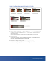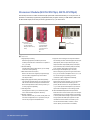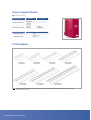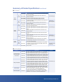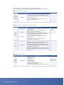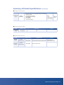
1
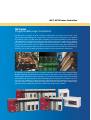
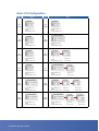
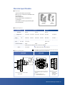
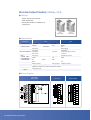
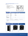
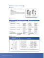
NX7, NX70 Series Controllers
Selection Guide
One Family of Programmable Logic Controllers
for Every Application and Budget
OE MAX ▶▶
Maximizing Operating Earnings for OEMs
OE MAX is a value-driven global brand offering
competitive control products and performancedesigned automation components developed
specifically to help small independent machine
builders maximize their operating earnings. OE MAX
offers the most complete and competitive one-stop
service for top quality, reliable components such as
PLCs, distributed I/O, servo drives, operator interface
panels and other industrial control products to meet
the needs of original equipment manufacturers.
With our professional team, we search the world for
products that offer the best quality for your
application. We understand the importance of
instilling confidence and trust in establishing longterm relationships with all our customers, regardless
of size. We seek to build relationships that lead to
mutual success for the benefit of our people, their
families, and their communities.
OE MAX is a unique
brand that delivers the best
products from all over
the world to you by a
network of distributors who
understand your control
and automation needs.
OE MAX provides performance-designed automation
components at a price less than you expect to pay to
help independent OEMs maximize operating earnings.
Moreover, OE MAX optimizes the cost of equipment
and is committed to delivering the most cost-effective
control components that meet the specifications for
your machine.
Through our catalogs and full featured web site, you
will find the most suitable automation products that
meet your specific needs. OE MAX will grow to meet
your needs through the continued introduction of new
products and strives to be one of the best suppliers of
industrial automation products.
NX7, NX70 Series Controllers
NX Series
Programmable Logic Controllers
The NX series is a family of small, modular programmable controllers from OE MAX. They
deliver power and flexibility with a wide range of communication configurations, user features
and memory options. The NX series offers a breadth of controllers that satisfies a wide variety of
OEM applications. This ensures you’ll find a world class PLC that fits your application as easily as
one that fits your budget. This integrated and ultra-compact PLC series is equipped with
advanced control functions and up to 384 I/O points, easily handling most OEM applications. In
addition, the NX series products have built-in real-time clocks and user-defined communication
functions, such as ASCII, satisfying the diverse needs of original equipment manufacturers
All members of the NX series share a common architecture and use the same industry leading
WinGPC programming software, so you don’t have to reprogram or learn a new system as your
needs change. With the NX series controllers, you can finally have the ideal blend of functionality
and compact size, at a price that is more reasonable than you might expect. The NX7 is an all-inone micro PLC suitable for compact machinery, offering task-specific dedicated control at a very
low price. NX70 is a modular, small PLC designed to handle an extensive range of applications,
expansion I/O up to 384 digital points and a wide range of optional I/O modules.
Table of Contents
NX7 Series
Product Overview
5
Features and Functions
5
Basic I/O Configurations
6
Specifications
7
Output Wiring Diagrams
10
Product Dimensions
14
Summary of Product Specifications
15
NX70 Series Product Overview
i I Table of Contents
17
Features and Functions
17
System Configuration
18
Basic Configurations and I/O Control Points
19
Processor Module (NX70-CPU70p1, NX70-CPU70p2)
20
Power Supply Module
22
I/O Backplane
22
Discrete Input Module
23
Discrete Output Module - (1) Relay, SSR
24
Discrete Output Module - (2) Transistor
25
Discrete Combo I/O Module
26
Analog Input Module (A/D Module)
27
Analog Output Module (D/A Module)
28
RTD (Resistance Temperature Detector) Module
29
Thermocouple (TC) Module
30
High-Speed Counter (HSC)
31
High-Performance High-Speed Counter (4CH)
33
Pulse I/O Module (4CH)
35
Serial Communication Unit (SCU)
37
MW-Link Module
38
Cables for Processor Module (NX70-CPU70p1, NX70-CPU70p2)
39
Cables for NX70 SCU Module
40
WinGPC Programming Software
41
Product Dimensions
42
Summary of Product Specifications
44
NX7 Series
Micro Logic Controller
Features of NX7S
�Control 10,14,20,28,40,48 digital I/O points
�2 serial ports (1 RS-232C, 1 RS485 with Modbus RTU)
�Program memory size up to 2K words
�Built-in backup flash memory
�Built-in HSC, Pulse output(for TR output module only)
Features of NX7
�Basic control to 28, 48 points and up to 104 digital I/O points
� Enable 2 expansion module
� 2 serial ports (2 RS232C/RS485 with Modbus RTU)
� Program memory size up 9K words
�Built-in HSC, Pulse catch, Pulse output
(for TR output module)
� Built-in real-time clock, PID function
Model Classification Series
NX7S
The perfect controller for
small applications and small
budgets. This little powerhouse
is both compact and inexpensive,
but it's big on performance-providing high-speed advanced
networking and a full suite of
control capabilities. Among the
advantages of the NX7 are a
compact design that takes up
little panel space and fast
program scan time that keeps
your machines on the
cutting edge.
Basic
Points
10 points
14 points
20 points
28 points
40 points
48 points
Power
Supply
AC100/220
AC100/220
AC100/220
AC100/220
AC100/220
AC100/220
DC IN/
Relay Out
NX7S-10ADR
NX7S-14ADR
NX7S-20ADR
NX7S-28ADR
NX7S-40ADR
NX7S-48ADR
DC IN/
TR(sink) Out
NX7S-10ADT
NX7S-14ADT
NX7S-20ADT
NX7S-28ADT
NX7S-40ADT
NX7S-48ADT
Power
Supply
AC100/220
DC 24V
AC100/220
DC 24V
-
DC IN/
Relay Out
NX7-28DDR
NX7-28DDR
NX7-48DDR
NX7-48DDR
NX7-28EDR
DC IN/
TR(sink) Out
NX7-28ADT
NX7-28ADT
NX7-48ADT
NX7-48ADT
NX7-28EDT
NX7
Basic
Points
28 points
28 points
48 points
48 points
Expansion
NX7 Series Small Logic Controller I 5
Basic I/O Configuration
Point
NX7s
Point
NX7
28
points
10
points
Input
6 points (R0.0 to 0.5)
Output
4 points (R16.0 to 16.3)
Input
16 points (R0.0 to 1.7)
Output
12 points (R16.0 to 17.3)
48
points
14
points
Input
8 points (R0.0 to 0.7)
Output
6 points (R16.0 to 16.5)
Input
28 points (R0.0 to 3.3)
Output
20 points (R16.0 to 18.3)
56
points
20
points
Input
32 points (R0.0 to 1.7)
Output
24 points (R16.0 to 17.3)
Input
12 points (R0.0 to 1.3)
Output
8 points (R16.0 to 16.7)
(R8.0 to 9.7)
(R2.4 to 25.3)
76
points
28
points
Input
16 points (R0.0 to 1.7)
Output
12 points (R16.0 to 17.3)
Input
44 points (R0.0 to 3.3)
Outputt
32 points (R16.0 to 3.3)
(R8.0 to 9.7)
(R24.0 to 25.3)
84
points
40
points
Input
24 points (R0.0 to 2.7)
Output
16 points (R16.0 to 17.7)
Input
48 points (R0.0 to 1.7)
Output
36 points (R16.0 to 17.3)
(R8.0 to 9.7)
(R12.0 to 14.7)
(R24.0 to 25.3)
(R28.0 to 29.3)
104
points
48
points
Input
28 points (R0.0 to 3.3)
Output
20 points (R16.0 to 18.3)
6 I NX7 Series Small Logic Controller
Input
60 points (R0.0 to 1.7)
Output
44 points (R16.0 to 18.3)
(R8.0 to 9.7)
(R12.0 to 13.7)
(R24.0 to 25.3)
(R28.0 to 29.3)
Features and Functions, Basic I/O Configurations
Specifications
■ Performance specifications
Item
NX7s
10xxx
14xxx
20xxx
NX7
28xxx
40xxx
48xxx
28xxx
2K words
Program Memory
48xxx
9K words
Data Memory
R000.00 to R31.15 (512 Points, 32 Words)
I/O (R)
512 Points
(R32 to R127 for the special functions
Internal relay (M)
M000.00 to M127.15 (2,048 Points, 128 Words)
Keep relay (K)
2,048 Points
K000.00 to K127.15 (1,024 Points, 64 Words)
1,024 Points
W0000 to W2,047 (2,048 Words
2048 words (Keep data)
Data register (W)
256 Channels, Setting value range: 0 to 65535
Timer/Counter (TC)
TC000 to TC063: 0.01 sec time base
256 Channels
TC064 to TC255: 0.1 sec time base
Special Contact(F)
F000.00 to F015.15 (256 Points, 16 Word
256 Points
Special Area (SR)
SR000 to SR511 (512 Words)
(512 Words)
Basic I/O Points
Maximum
10
14
20
28
40
48
84
104
Base I/O
10
14
20
28
40
48
28
48
No. of input
6
8
12
16
24
28
12
28
4
6
8
12
16
20
16
20
28
28
No. of output
Expansion I/O Points
Expansion quantity
2 Modules
2
2
COM1
RS-232C (D-sub 9pin)
RS-232C/RS485 (Dsub 9pin)
COM2
RS485 (Modular type)
RS-232C/RS485(Modular)
Communication Port
Modbus RTU
Yes (Com2 port)
User Define Protocol
Yes (Com2 port)
Special Function
High Speed Counter
1 Ch ( 5KHz/2 Phase, 10KHz/1 Phase), 32Bit, 1*)
Input Pulse Catch
Pulse Output
4 points
2 Ch(for TR Output module), PWM/Pulse(PTO) mode, 10KHz, 32Bit, 1*)
Real Time Clock
Built-in
PID Function
Yes (8 loop)
Program Backup
EEPROM
SRAM or EEPROM
Data Backup
EEPROM
SRAM w/Battery
Service Power(24Vdc)
200 mA
400 mA
DIN Rail or Panel
Mounting
Dimension(W*H*D)
100*90*80
146*90*80
100*90*80 146*90*80
*1 : F/W Version 2.0 이상에서만 32 bits 가능
*2 : NX7s 의 경우 Timer/Counter 의 Back up 이 일부만 지원됨 (상세내용은 매뉴얼 참조)
NX7 Series Small Logic Controller I 7
Specifications continued
■ General specifications
Item
Specifications
Power voltage
Allowed momentary
power failure
Operating temperature
110V ac, 220V ac (50 to 60 Hz) free voltage
20 ms or less
0 to 55�
C
Storage temperature
-10 to 75�
C
Operating humidity
30 to 85%, Non-condensing
Storage humidity
30 to 85%, Non-condensing
Vibration immunity
Shock immunity
Noise immunity
Isolation resistance
Withstand voltage
Frequency 16.7 Hz, 3 mm peak, 2 hours per axis
(X, Y, Z)
10 g, two times per each X, Y, Z direction
Noise voltage 1500 Vp-p with 100 ns to 1μ
s pulse width
(The tests are based on our company’
s rule.)
20 M Ω or more at 500 mega V dc between ac
external terminal and frame ground (FG) terminals.
1500V ac for 1 minute between the ac external
terminal and frame ground (FG) terminal
Grounding
3-type grounding or more
Ambience
No corrosive gas, no excessive dust
Structure
Open, wall-mounted type
Value retention
Up to 10 days at 25�
C (retains retentive relay values)
■ Power specifications
Type
AC
Specifications
Rated voltage
110V to 220V ac, free voltage
Voltage range
85 to132V ac, 170 to 264V ac
Frequency
Power consumption
Output current
capacity
DC
8 I NX70 Series Small Logic Controller
47 to 63 Hz,
Max. 33 Watts
Internal: 2.0A at 5V External (for services)
: 0.4A at 24V
Rated voltage
24V dc
Voltage range
21.6 to 26.4V dc
Output
Internal: 2.0A at 5V, External: 0.4A at 24V
current
(direct connection)
Specifications continued
■ Input specifications
Item
DC Input
Rated voltage
12 to 24V dc input
Voltage range
10.8 to 26.4V
Max. input current
10 mA or less
Min. on voltage/current
10.0V or more/3.0 mA or more
Max. off voltage/current
5.0V or less/0.6 mA or less
Input impedance
Approx. 3.6 K Ω
Response
Off → On
2 ms or less
time
On → Off
2 ms or less
Polarity
No polarity
Common method
8 points/COM, 16 points/COM
Internal circuits (transistor output)
■ Output specifications
Item
Transistor output
Rated load voltage
12 to 24V dc
Load voltage range
10 to 30V dc
Polarity
Sink Type, NPN
Max. load current
Response
time
Internal circuits (dc input)
0.4A/point, 1A/COM
Off → On
10 ms or less
On → Off
10 ms or less
Common method
1, 4, 6 points/COM
Internal 0v
GND
10 to 30v dc
External power supply
Item
Relay output
Rated load voltage
250V ac, 30V dc
Load voltage range
85V to 264V ac
Polarity
3A or less
No polarity
Max. load current
Response
time
Internal circuit (relay output)
2A/point, 6A/COM
Off → On
10 ms or less
On → Off
10 ms or less
Common method
1, 4, 6 points/COM
5 to 30v dc or
100 to 220v ac
NX7 Series Small Logic Controller I 9
Output Wiring Diagrams
■ NX7s-10ADR Output Wiring Diagrams
Internal circuit
Vcc
OUT 2A
load
COM 5 to 30V dc
100/220V ac
■ NX7s-10ADT Output Wiring Diagrams
VDC
Internal circuit
OUT 60 to 400mA
load
Vcc
COM
Internal 0V
10 to 30V dc
■ NX7s-14ADR Output Wiring Diagrams
Internal circuit
Vcc
OUT 2A
load
COM 5 to 30V dc
100/220V ac
10 I NX7 Series Small Logic Controller
Output Wiring Diagrams continued
■ NX7s-14ADT Output Wiring Diagrams
VDC
Internal circuit
OUT 60 to 400mA
load
Vcc
COM
10 to 30V dc
Internal 0V
■ NX7s-20ADR Output Wiring Diagrams
Internal circuit
Vcc
OUT 2A
load
COM 5 to 30V dc
100/220V ac
■ NX7s-20ADT Output Wiring Diagrams
Internal circuit
24Vdc
Internal power
OUT 60 to 400mA
load
Vcc
COM
Internal 0V
10 to 30V dc
■ NX7-28ADR, NX7s-28ADROutput Wiring Diagrams
Internal circuit
Vcc
OUT 2A
load
COM 5 to 30V dc
100/220V ac
NX7 Series Small Logic Controller I 11
Output Wiring Diagrams continued
■ NX7-28ADT, NX7s-28ADT Output Wiring Diagrams
Internal circuit
24Vdc
Internal power
OUT 60 to 400mA
load
Vcc
COM
Internal 0V
10 to 30V dc
■ NX7-28DDR Output Wiring Diagrams
Internal circuit
Vcc
OUT 2A
load
COM 5 to 30V dc
100/220V ac
■ NX7-28DDT Output Wiring Diagrams
Internal circuit
24Vdc
Internal power
OUT 60 to 400mA
load
Vcc
COM
Internal 0V
■ NX7s-40ADR Output Wiring Diagram
12 I NX7 Series Small Logic Controller
10 to 30V dc
Output Wiring Diagrams continued
■ NX7s-40ADT Output Wiring Diagram
■ NX7-48ADR, NX7s-48ADR Output Wiring Diagram
■ NX7-48ADT, NX7s-48ADT Output Wiring Diagram
■ NX7-48DDR Output Wiring Diagram
■ NX7-48DDT Output Wiring Diagram
NX7 Series Small Logic Controller I 13
Product Dimensions
10 to 28-points PLC
35mm
mounting
DIN rail
100.0mm
¥ 4.2
9.5
81.0
90.0
87.0
9.5
1.5
3.0
40 to 48-points PLC
35mm
mounting
DIN rail
146.0mm
¥ 4.2
10.0
126.0
87.0
10.0
1.5
3.0
14 I NX7 Series Small Logic Controller
Summary of Product Specifications
■ Base Controllers
Catalog
Number
Input
Power
NX7-48ADR
100 to
240V ac
power
supply
16-point dc input
12-point transistor output
28-point dc input
20-point relay output
NX7-48ADT
28-point dc input
20-point transistor output
NX7-28DDR
16-point dc input
12-point relay output
NX7-28DDT
16-point dc input
12-point transistor output
NX7-48DDR
24V dc
power
supply
28-point dc input
20-point relay output
NX7-48DDT
28-point dc input
20-point transistor output
NX7s-10ADR
6-point dc input
4-point relay output
NX7s-10ADT
6-point dc input
4-point transistor output
NX7s-14ADR
8-point dc input
6-point relay output
NX7s-14ADT
8-point dc input
6-point transistor output
NX7s-20ADR
12-point dc input
8-point relay output
NX7s-20ADT
NX7s-28ADR
Remarks
16-point dc input
12-point relay output
NX7-28ADR
NX7-28ADT
I/O specifications
100 to
240V ac
power
supply
12-point dc input
8-point transistor output
16-point dc input
12-point relay output
NX7s-28ADT
16-point dc input
12-point transistor output
NX7s-40ADR
24-point dc input
16-point relay output
NX7s-40ADT
24-point dc input
16-point transistor output
NX7s-48ADR
28-point dc input
20-point relay output
NX7s-48ADT
28-point dc input
20-point transistor output
� BuiIt-in 9k steps memory
� Several μ
s per step processing speed
� Built-in 1 HSC input channel
� Built-in 2 pulse output channels built in
� 2 communication ports
�Expandable to up to two
expansion modules
(NOTE: Some relevant
contacts are unavailable
when HSC input or pulse
output channels are used.)
�Built-in 2k steps memory
�Several μ
s per step processing speed
� Built-in 1 HSC input channel
�Built-in 2 pulse output channels built in
�2 communication ports
COM1 : RS232C
COM2 : RS485
� Expansion unsupported
(NOTE: Some relevant
contacts are unavailable
when HSC input or pulse
output channels are used.)
NX7 Series Small Logic Controller I 15
Summary of Product Specifications continued
■ Expansion Modules
Catalog
Number
Input
Power
I/O specifications
NX7-28EDR
24V dc
power
supply
16-point dc input
12-point relay output
NX7-28EDT
24V dc
power
supply
16-point dc input
12-point transistor output
Remarks
� 16-point 24V dc input
�12-point relay output
2A per point
� 16-point 24V dc input
�12-point transistor output
4A per point
■ Programming Software
Catalog
Number
Specifications
Remarks
Allows you to perform the following tasks on a
remote computer.
� PLC program editing anf monitoring
�file management
WinGPC
(Windows)
� Program back up
� online editing (instruction change only)
� error and status check-up
For Windows 95/98/
2000/NT
� network status check-up
� I/O mappinging
� Itime chart monitioring
■ Cables
Catalog
Number
NX_CBLCPU02
NX_CBLCPU05
16 I NX7 Series Small Logic Controller
Specifications
PLC to PC communication (WinGPC)
cable length : 2m
Same functions PLC to PC communication (WinGPC)
cable length : 5m
Remarks
Communication cable
for both RC232C and RS485
NX70 Series
Small Logic Controller
Features
�Fast, powerful processors
High speed basic instructions-performance-0.2μ
sec/STEP
�Control up to 384 digital I/O points
The 12-slot NX70 allows up to 384 points (192 points
using terminal blocks)
�Various I/O types and specialty modules
Digital In : 24V dc (16 point, 32 point), 110V ac, 220V ac
Digital Out : relay, transistor (16 point, 32 point), SSR,
combo I/O
Special I/O: A/D (8Ch,4Ch), D/A (4Ch, 2Ch), RTD (4Ch),
TC (4Ch), PULSE (4Ch HSC)
SCU (2Ch Serial Data Comm. ) and link network
�Range of I/O base options (up to 12 slot)
When configuring a system, PLC NX Series enables you
to choose a backplane from 2, 3, 5, 6, 8, 10, and 12 slots
Whatever your control
needs are, you will find an
answer with the NX70 series.
The NX70 is filled with
features and options designed to
handle an extensive range of
OEM applications. Advantages of
the NX70 include: Scalable
program memory and backplane
options to ensure you only buy
what you need. A wide range of
optional I/O modules to match
your machines' unique
specifications. Run time editing
for faster machine start-up,
commissioning and process
improvements, without costly
down-time. Best of all, you get
all this functionality and quality
at a really great price.
�High capacity programming and memory backup option
Program memory size is from 9.6k words (NX70CPU70P1) up to 20k words (for NX70-CPU70P2). Built-in
flash EEPROM retains all ladder logic
�Built-in PID capabilities
Supports 8-loop PID controls (Only for NX70-CPU70P2 module)
�Built-in RTC (Real Time Clock)
Built-in real time clock supports programming by time
and date. (Only for NX70-CPU70P2 module)
�Built-in RS 232C and RS 485, 2port (NX70-CPU70p2 module)
Two communication channels for simple connectivity to
computers, operator interface, modem and other
controllers to exchange large volumes of data with high
speed. COM2 port supports user defined communications
to connect you to barcode readers, inverters, modbus
slave, or servos. (Binary communications available)
�Superior diagnostics
Self-diagnostics to minimize system errors and to
maximize diagnostic efficiency
�WinGPC programming software
WinGPC programming software lets you create, modify
and monitor CPU, forced I/O, I/O configuration. It is a
powerful, easy-to-use tool for program upload/download
NX70 Series Small Logic Controller I 17
NX70 Series Small Logic Controller
System Configuration
Processor
Module
∙ NX70-CPU70p1
9.6k words
1 Comm. port
∙ NX70-CPU70p2
20k words
2 Comm. ports
Power Supply
Module
∙ AC Type
1) NX70-POWER1
(110/220V input,
free voltage)
3.5A at 5V, 0.3A at 24V
2) NX70-POWER2
(110/220V input,
free voltage)
4.5A at 5V
∙ DC Type
1) NX70-PWRDC
(24V dc input)
4.5A at 5V
18 I NX70 Series Small Logic Controller
Discrete Module
Analog Module
Special Module
∙ 8 points I/O module
∙ 4, 8 channel A/D module
∙ 1,2,4 channel HSC module
∙ 16 points I/O module
∙ 2, 4 channel D/A module
∙ 4 channel Pulse output moduel
∙ 32 points I/O module
∙ 4 channel RTD module
∙ Serial Communication module
∙8 points input, 8 points
∙ 4 channel TC module
∙ Multi-Wire Link module
output combo module
∙16 points input, 16 points
output combo module
*
I/O Backplane
∙ 2-slot type
∙ 3-slot type
∙ 5-slot type
∙ 6-slot type
∙ 8-slot type
∙ 10-slot type
∙ 12-slot type
Basic Configuration and I/O Control Points
■ 2-Slot Type
■ 3-Slot Type
■ 5-Slot Type
■ 6-Slot Type
up to 32 points with 16-point I/O
up to 48 points with 16-point I/O
up to 80 points with 16-point I/O
up to 96 points with 16-point I/O
up to 64 points with 32-point I/O
up to 96 points with 32-point I/O
up to 160 points with 32-point I/O
up to 192 points with 32-point I/O
■ 8-Slot Type
■ 10-Slot Type
up to 128 points with 16-point I/O
up to 160 points with 16-point I/O
up to 256 points with 32-point I/O
up to 320 points with 32-point I/O
■ 12-Slot Type
up to 192 points with 16-point I/O
up to 384 points with 32-point I/O
■ Flexible System Configuration: 7 Types of Backplane (2-, 3-, 5-, 6-, 8-, 10- and 12-Slot)
The NX70 PLC has 7 types of backplane (2-, 3-, 5-, 6-, 8-, 10 and 12-slot type), providing you with very
flexible I/O configuration.
Backplane, I/O, power supply and specialty modules are available regardless of processor type.
■ Number of Slots
The last 2 digits of the catalog number of a backplane (for example, 12 in NX70-BASE12) indicate the
total number of I/O and specialty modules that can be mounted.
■ Maximum of 384 I/O Control Points
With 12-slot NX70 PLC, you can use up to 384 I/O points (using 32-point module).
With terminal block type PLC, up to 192 points are available (using 16-point module).
The NX70 PLC is not expandable to other racks.
NX70 Series Small Logic Controller I 19
Processor Module (NX70-CPU70p1, NX70-CPU70p2)
The NX70 processor module combines high speed with multi-functionality in a compact size. It
provides convenient programming capabilities with program memory of 9.6k words (20k words
for NX70-CPU70p2) and a fast processing speed of 0.2 ㎲ per instruction.
Communication cable
(NX_CBLCPU2/CBLCPU5)
NX70-CPU70p1
NX70-CPU70p2
∙ 9.6K word memory
∙ 20K word memory
∙ 1 port(RS232/RS485)
∙ 2 port(RS232/RS485)
∙ Battery and Flash memory
∙ Flash ROM backup
backup
PC
(WinGPC software)
∙ User defined protocol
∙ Built-in RTC
∙ PID
■ Features
1. High-speed processing
7. Supports various I/O types and special modules
With the high-speed IC, the NX70 processor
The CPU70px processor module supports 24V dc input
module processes basic instructions at a speed of
(16/32 points), 110V ac input, 220V ac input, relay
0.2 ㎲ per step.
output, transistor output (16/32 points), SSR output,
2. Runtime Editing
The NX70-CPU70px module allows you to modify
instruction while operating.
3. Built-In Real Time Clock (RTC)
A/D (4 channels), D/A (4 channels), RTD (4 channels),
TC (4 channels), high-speed counter, and SCU.
8. Various types of backplane (up to 12 slots)
When configuring a system using an NX70 series
Built-in real time clock supports programming by
PLC, you can choose a backplane from 2, 3, 5, 6, 8,
time and date. (Supported only for the NX70-
10, and 12 slot types, providing you with
CPU70p2 module.)
4. High-capacity program memory and memory backup
maximum system configuration flexibility.
9. Control up to 384 I/O points
The CPU70px module allows you to program up to
With 12-slot processor module, you can use up to
20K words for NX70-CPU70p2, and 9.6k words for
384 I/O points (with terminal block type, 192
NX70-CPU70p1. Built-in flash memory allows you
points). NX70 series PLC is not expandable. That
to save programs separately.
is, you must replace the backplane if you want to
5. Self-diagnostics
Self-diagnostics allows you to minimize system
errors and maximize diagnostic efficiency.
6. WinGPC software
expand the configuration of an existing system.
10. Built-in RS232C/RS485 ports (NX70-CPU70p2 module)
With two built-in communication ports, the CPU70p2
module allows you to connect directly to computers
WinGPC software lets you create, modify CPU and
or touch panels and exchange a high volume of data
forced I/O configurations. It is a powerful, easy-to-
at high speed. The COM2 port supports a simple
use tool for program unload/download.
user-defined communication, and allows you to
connect to barcode readers, inverters, or servo
motors. (Binary communication is available.)
20 I NX70 Series Small Logic Controller
Processor Module (NX70-CPU70p1, NX70-CPU70p2) continued
■ Specifications
Processor Type
NX70-CPU7p1
Control method
NX70-CPU7p2
Stored program, cyclic operation
Number of I/O
384 points (32-point module/12 slots)
Instructions
Basic
28 types
Advanced
150 types
Basic
Process speed
Advanced
Program memory
0.2 ㎲ per step
1.0 to several tens of ㎲ per step
9.6k words
Local I/O(R)
Link contact(L)
Internal contact(M)
Keep contact(K)
Special contact(F)
Data memory
20k words
R0.0 to R127.15 (2,048 points)
L0.0 to L63.15 (1,024 points)
M0.0 to M127.15 (2,048 points)
(Note: Available as link contact for NX70-CPU70p2, 64 words)
K0.0 to M127.15 (2,048 points)
SR000 to SR511 (512 words)
256 channels (Timer + Counter), Set value range: 0 to 65535
Timer / Counter
Timer: 0.01 second: CH000 to CH063 (64 channels),
(TC or TIM)
0.1 second: CH064 to CH255 (192 channels)
Counter: CH000 to CH255 (256 channels)
Data register(W)
Special register(SR)
W0000 to W2047 (2,048 words)
W3072 to W5119 (4,096 words)
SR000 to SR511(512 words)
Not applicable
Real time clock
Year, Month, Date, Hour,
Minute, Second, Day of the week
Port 1
Supports both RS232C and RS485, 4800/ 9600/ 19200/ 38400 bps
Not applicable
Communications
W0000 to W2047,
Port 2
Supports both RS232C and
RS485, 4800 to 38400 bps
Supports a user-defined protocol
Backup using flash memory
built-in processor module
. Keep contact (K), data register (W), and counter’s preset value register retain their last values before power was removed.
. The super capacitor in the processor module backups all user programs and specific registers for up to 48 hours, even in the event of a power
failure.
■ General Specifications
Specification
Item
Temperature
Humidity
Operating
0 ℃ to +55 ℃ (32 ℉ to 131 ℉)
Storage
-25 ℃ to +70 ℃(-13 ℉ to ℉ 158 )
Operating
30 to 85% RH (Non-condensing)
Storage
30 to 85% RH (Non-condensing)
Withstand voltage
1500V ac for 1 minute between I/O terminal (ac) and frame ground (power supply module)
1500V dc for 1 minute between I/O terminal (dc) and frame ground (power supply module)
Isolation resistance
10 M Ω or more at 500 mega V dc between I/O terminal (ac) and frame ground (power supply module)
Vibration immunity
10 to 55 Hz 1 sweep per minute, 0.75 mm peak to peak, 10 minutes per axis (X, Y, Z)
Shock immunity
15 g peak acceleration (11 ms duration) 3 times, each X, Y, Z direction
Noise immunity
1500 Vp-p with 50 ns to 1 ㎲ pulse width (generated by noise simulator)
Ambience
No corrosive gases, no excessive dust
NX70 Series Small Logic Controller I 21
Power Supply Module
■ Specifications
Catalog number
NX70-POWER1
NX70-POWER2
Rated input voltage
110 to 220V ac, free voltage
Input voltage range
85 to 264V ac
Input power frequency
47 to 63 Hz
Inrush current
20A or less
Rated output current at 5V
3.5A at 5V
4.5A at 5V
Rated output current at 24V
0.3A at 24V
Not applicable
Catalog number
NX70-PWRDC
Rated input voltage
24V dc
Input voltage range
24V dc ± 10%
Rated output current
4.5A at 5V
Power Supply Module
I/O Backplane
2-slot backplane
(NX70-BASE02)
8-slot backplane
(NX70-BASE08
3-slot backplane
(NX70-BASE03)
10-slot backplane
(NX70-BASE10)
5-slot backplane
(NX70-BASE05)
6-slot backplane
(NX70-BASE06)
12-slot backplane
(NX70-BASE12)
NOTE The last 2 digits of the catalog number of a backplane (for example, 12 in NX70-BASE12) indicates the total number of I/O and specialty
modules that can be mounted.
22 I NX70 Series Small Logic Controller
Discrete Input Module
■ Features
�16-point and 32-point input modules
�Both of + and - commons are available for the
DC input type.
�Status display LED
�Photocoupler isolation available for all
module types.
�The 32-point connector type provides higher
input point density.
16-point
32-point
Input Module
Input Module
■ Specifications
DC Input
Input type
Catalog number
NX70-X16D
16points
Input point
Rated input voltage
Voltage range
Max. input current
12 to 24V dc
AC Input
NX70-X16D1 NX70-X32D
NX70-X32D1 NX70-X16A110
32points
24V dc
NX70-X16A220
16points
12 to 24V dc
24V dc
100 to 120V ac
10.2 to 26.4V dc 21.6 to 26.4V dc 10.2 to 26.4V dc 21.6 to 26.4V dc 85 to 132V
10 mA or less
200 to 240V ac
170 to 264V ac
20 mA or less
Operation
On
9.6V or more 20V or more
9.6V or more 20V or more
80V or more
160V or more
voltage
Off
2.5V or less
2.5V or less
30V or less
50V or less
Approx. 3K Ω
Approx. 15K Ω
Approx. 20K Ω
Input impedance
7V or less
7V or less
Response
Off → On
2.0 ms or less
15 ms or less
time
On → Off
2.0 ms or less
15 ms or less
Internal
current consumption
Common method
External connection method
Option
<50mA
8 points per common (Both of+ and - commons are available)
8 points per common
Terminal block(M3.0)
Two 20-pin connector
Terminal block(M3.0)
Not applicable
NX70_CBLDC expansion cables
Not applicable
■ Wiring Diagram
NX70-X16D
NX70-X16D1
(Note 1) The input voltage for the NX70-X16D1
module is 24V dc.
<80mA
<90mA
Note
The numbers (1~20) in the following diagram (NX70-X32D, NX70-X32D1) are
the numbers printed on the front of the product.
NX70-X32D
NX70-X32D1
NX70-X16A110
NX70-X16A220
※ The connectors (I) and (II) are positioned in
opposite directions. Please use caution prior to
connecting.
(Note 1) The input voltage for the
NX70-X32D1 module is 24V dc.
(Note 1) The input voltage
for the NX70X16A220 module is
200 to 240V ac.
NX70 Series Small Logic Controller I 23
Discrete Output Module-(1)Relay, SSR
■ Features
� 8-point, 16-point output module
� Status display LED
�Photocoupler isolation is available for all
module types
8-point
16-point
Output Module
Output Module
■ Specifications
Output type
Relay
Catalog number
NX70-Y16R
Output point
NX70-Y16RV
16points
SSR
NX70-Y8R
NX70-Y16SSR
8points
16points
Photo coupler
Isolation method
SSR
Rated load voltage
250V ac 30V dc
Rated load voltage range
85V ac 264V dc
Max. load current/com
1A per point
Response
Off → On
10ms or less
1 ms or less
time
On → Off
10ms or less
0.5CYCLE + 1ms or less
Internal current
consumption(5V)
Surge absorber
Rated fuse
Common method
Status Display
External connection
method
100V to 240V ac
85V to 264V ac
3A per point
100mA
NA
60mA
Varistor
250mA
Varistor
3.0A
None
8points per common
0.5A per point, 2A per common
1points x 4, 4 points x1 8 points per common
LED(NOTE : The 32 points for conversion are displayed every 16 points)
Terminal block (M 3.0)
■ Wiring Diagram
NX70-Y16R
NX70-Y16RV
24 I NX70 Series Small Logic Controller
NX70-Y8R
NX70-Y16SSR
Discrete Output Module-(2)Transistor
■ Features
� 16-point, 32-point output module
� Status display LED
�Photocoupler isolation is available for all
module types
�The 32-point connector type provides higher
output point density.
16-point
32-point
Output Module
Output Module
■ Specifications
Transistor
Output type
Catalog number
Output point
Isolation method
NPN
NX70-Y16T
NX70-Y32T
16points
32points
Photocoupler
Rated load voltage
12V to 24V dc
12V to 24V dc
Rated load voltage range
10V to 30V dc
10V to 30V dc
Max. load current
0.6A per points
0.4A per points
Response
Off → On
1 ms or less
time
On → Off
1 ms or less
Internal current
consumption(5V)
Surge absorber
Rated fuse
Common method
Status Display
External connection
method
Option
PNP
NX70-Y32P
140mA
80mA
Zener Diode
None
8points per common (-)
16points per common(+)
16points per common(-)
LED(NOTE : The 32 points for conversion are displayed every 16 points)
Terminal block (M 3.0)
Two 20-pin connectors
Not applicable
Two 1.5m NX70_CBLTR expansion cables
■ Wiring Diagram
NX70-Y16T
NX70-Y32T
NX70-Y32P
※ The connectors (I) and (II) are positioned
in opposite directions.
Please use caution prior to connecting.
※ The connectors (I) and (II) are positioned
in opposite directions.
Please use caution prior to connecting.
NX70 Series Small Logic Controller I 25
Discrete Mixed I/O Module
Discrete Combo I/O Module
■ Features
� 16-point and 32-point Combo I/O modules
�Both of + and - commons are available for the DC
input type.
� Status display LED
�Photocoupler isolation available for all module types.
�The 32-point connector type provides higher input
point density.
8-point dc input
8-point relay output
Combo I/O module
16-point dc input
16-point TR output
Combo I/O module
■ Specifications
Product name
16-point Discrete Combo I/O Module
(Combing dc input and relay output)
NX70-XY16
Catalog number
I/O points(16 points)
Isolation method
32-point Discrete Combo I/O Module
(Combing dc input and transistor output)
8 dc input points
8 relay output points
Photocoupler
NX70-XY32
16 dc input points
16 TR output points
Photocoupler
12 to 24V
Not applicable
12 to 24V
Not applicable
Voltage range
10.2 to 26.4V
Not applicable
10.2 to 26.4V
10 to 30V dc
Max. input current
10mA or less
Not applicable
10mA or less
Not applicable
Rated voltage/current
Not Applicable
250V ac, 30V dc,1A per point
Not Applicable
12 to 24V dc,0.4A per point
On voltage/On current
9.6V or less / 4mA or less Not applicable
9.6V or less / 4mA or less Not applicable
Off voltage/Off current
Rated input voltage
2.5V or less / 1.5mA or less Not applicable
2.5V or less / 1.5mA or less Not applicable
Input impedance
Approx. 3K Ω
Approx. 3K Ω
Not applicable
Surge absorber
Not applicable
Not applicable
Zenor diode
Not required
24V 200 mA or less
Not required
Not Applicable
Off → On
2ms or less
10ms or less
2ms or less
1 ms or less
On → Off
2ms or less
10ms or less
2ms or less
1 ms or less
8points per common(Both of
16 points per
External power supply
Response time
Not applicable
8points per common(Both of
Common method
External connection method
Recommended cable size
+and -commons are available.)
8 points per common
+and -commons are available.) common (-)
Terminal block (terminal screw : M3.0)
Two 20-pin connectors
0.5 to 1.25 mm2
0.2mm2
■ Wiring Diagram
NX70-XY16
NX70-XY32
NX70-XY16
※ We recommend you should purchase separately a connector harness (NX70_CBLDC for dc input,
NX_70CBLTR for transistor output) or pin type connector assembly (NX70_PIN20) for external
connections. For more information on wiring, refer to NX70 User Manual.
26 I NX70 Series Small Logic Controller
Analog Input Module (A/D Module)
Sensor
Temperature, speed, pressure, and flow
Transducer
Electric measurements (Voltage, current,
power, and frequency)
Measurement
instrument
Sensors
MQ laser sensor,
Displacement
Sensor
A/D Module (4CH)
(NX70-AI4V,
(NX70-AI4C)
A/D Module (8CH)
(NX70-AI8V,
(NX70-AI8C)
DSA displacement sensor
A/D Module
■ Features
Provides high-speed conversion speed and high-
4. Two programming methods
accuracy resolution, which are the deciding factors in
Provides two programming methods. You can
the performance of analog module.
select an appropriate method according to the
occupied I/O points:
1. Built-in 4 channels in a module
1. Using shared memory
2. High resolution
2. Using I/O contacts.
Provides max. resolution of 0.153 mV for voltage
5. Additional functions (e.g. scaling)
type, and 0.519 uA for current type. You can select
The A/D module is equipped with 16-bit A/D converter,
an appropriate resolution using the DIP switch.
providing high-accuracy conversion and high-speed
3. DC/DC converter and/or photocoupler insolation
processing of 1.25 ms per channel.
between the input channels and the internal circuit.
■ Specifications
Catalog numer
Analog input range
Numer of analog input channels
Digital conversion
Converter type
Votage Input
NX70-AI4V
Current Input
NX70-AI8V
Voltage : 0 to 10V, 0 to 5V, ± 10V, ± 5V,
4 channels
8 channels
NX70-AI8C
Current : 0 to 20mA, 4 to 20mA, ± 20mA
4 channels
8 channels
Signed 16-bit interger (2’s complement)
16-bit A/D conventer
0 to 10V (0 to 32767)
I/O characteristics *1
NX70-AI4C
0 to 20mA (0 to 32767)
0 to 5V (0 to 32767)
4 to 20mA (0 to 32767)
± 10V(-32767 to 32767)
± 20Ma(-32767 to 32767)
± 5V(-32767 to 32767)
Max. resolution *1
Overall accuracy
Conversion speed
0.153mV
0.519uA
± 0.2%/ full scale(25℃)
± 0.3%/full scale(25℃)
1.25ms per channel
External input impedance
500k Ω
249k Ω
Absolute maximum Input
Voltage :± 15V, Current :± 30mA
Voltage :± 7.5V, Current :± 30mA
Isolation method
Between input channel and internal circuits : DC/DC Converter, Photocoupler insulation
Between input channels : Non-isolation
Occupied I/O point
Other functions
∙ Shared memory type : 16points
Channel On/Off switching
Internal current consumption
Internal current (0.29A at 5V or less) (External 24V dc is not required.)
External connection method
Terminal block(terminal screw : M3.0)
*1. Both of I/O characteristics and maximum resolution can be set to from high to average by selecting the DIP switch located on the bottom of the
product. The conversion speed and stability for converted data depend on resolution.
NX70 Series Small Logic Controller I 27
Analog Output Module (D/A Module)
Inverter
M
Motor
Thermometer
D/A 2channels
(NX70-AO2V)
(NX70-AO2C)
D/A 4channels
(NX70-AO4V)
(NX70-AO4C)
D/A module
■ Features
Provides high-speed conversion speed and high-
4. Two programming methods for analog processing
accuracy resolution, which are the deciding factors in
Provides two programming methods. You can
the performance of analog module.
select an appropriate method according to the
1. Built-in 2 or 4 channels in a module
occupied I/O points:
2. DC/DC converter and/or photocoupler isolation between
1. Using shared memory
the input channels and the internal circuit.
2. Using I/O contacts.
3. High resolution
5. Additional functions (e.g. scaling)
Resolution is approximately max. 0.6 mV for
The D/A module contains a 14-bit D/A converter
voltage type and approximately max. 1.2 uA for
that processes data at high speed and accuracy.
current type.
■ Specifications
Catalog numer
Analog output range
Numer of analog output channels
Digital conversion
Converter type
Voltage output
NX70-A04V
NX70-A02V
Current output
NX70-A04C
± 10V, 0 to 10V, ± 5V, 0 to 5V
0 to 20mA, 4 to 20mA
4channels
4channels
2channels
NX70-A02C
2channels
Signed 16-bit integer(inary) (2’s complement)
14-bit D/A converter
1) ± 10V(-16,383 to 16,383)
I/O characteristics *1
2) 0 to 10V (0 to 16,383)
1) 0 to 20mA (0 to 16,383)
3) ± 5V(-16,383 to 16,383)
2) 4 to 20mA (0 to 16,383)
4) 0 to 5V (0 to 16,383)
Max. resolution *1
Overall accuracy
0.6mV
1.2 uA
± 0.2%/full scale(25℃ )
± 0.4%/full scale(25℃ )
Conversion speed
2.5 ms per channel
Output impedance
0.1 Ω or less
10M Ω or more
Output resistance
5K Ω or more
500 Ω or less
Isolation method
Occupied I/O points
Occupied I/O points
Other functions
Internal current consumption
External power supply
External connection method
∙Between output channel and internal circuits : DC/DC converter, photocoupler insulation
∙Between output channels : Non-insulation
∙Output contact type, 4 channels: 4 words (64 points), 2 channels: 2 words (32 points)
∙Shared memory type: 1 word (16 points)
∙Output contact type, 4 channels : 64-point output, 2channels : 32-point output
∙Shared memory type : 16 points
Data verification
0.33A or less at 5V
0.23A or less at 5V
0.6A or less at 5V
0.4A or less at 5V
Not required
Terminal block(terminal screw : M3.0)
*1. Both of I/O characteristics and maximum resolution can be set to from high to average by selecting the DIP switch located on the bottom of the
product. The conversion speed and stability for converted data depend on resolution.
28 I NX70 Series Small Logic Controller
RTD (Resistance Temperature Detector) Module
Three-wire RTD senser
(Pt100, JPt100...)
-200 to 850 ℃
-200 to 640 ℃
RTD module (4channels)
(NX70-RTD4)
RTD module
■ Features
Performs high-speed and high-accuracy processing
4. Two programming methods for analog processing
with an embedded 24-bit Σ-Δ A/D converter. It
Provides two programming methods. You can
features a variety of I/O ranges, as well as self-
select an appropriate method according to the
calibration.
occupied I/O points:
1. Built-in 4 channels in a module
1. Using shared memory
2. Supports various temperature sensor types
Available temperature sensor types should be of
2. Using I/O contacts.
5. Designed with high noise immunity
three-wire. Supported sensor types: pt100, pt200,
The analog and digital noise filters are attached on
pt500, pt1000, Jpt100, and Jpt200.
the inside of the module, which allows the module
3. Both Celsius (℃) and Fahrenheit (℉) data processing
You can select an option by adjusting the DIP
switch on the bottom of the module.
to resist environmental disturbances including
noise more effectively.
*Resistance Temperature Detector (RTD)
Based on the principle that resistance varies also as temperature varies.
It measures the voltage by flowing out a constant current into variable
resistance. V = I*R
■ Specifications
Catalog numer
RTD sensor
Digital conversion
Converter type
I/O characteristics(temperature
sensor and digital output)
NX70-RTD4(4 channels)
Three-wire type
Signed 16-bit integer (2’
s complement)
24-bit Σ-Δ A/D converter
① Pt100 (α
=0.00385, -200 to 850 ℃ => -2,000 to 8,500)
⑤ 300 Ω (10 m Ω per bit)
② Pt200, Pt500, Pt1000
⑥ 600 Ω (20 m Ω per bit)
③ JPt100 (α
=0.00385, -200 to 640 ℃ => -2,000 to 6,400)
⑦ 2000 Ω (100 m Ω per bit)
④ JPt200, JPt500, JPt1000
⑧ NI100, NI120, CU1
Max. resolution
0.1 ℃, 0.1 ℉, 10 m Ω, 20 m Ω
Overall accuracy
± 0.1% /full scale (25 ℃)
Conversion speed
External input impedance
Current source
Isolation method
Occupied I/O points
Internal current consumption
External power supply
External connection
60 ms per channel
10 M Ω
1 mA (excitation current)
Between input channel and internal circuit: DC/DC converter, photocoupler isolation
Between input channels: Non-isolation
∙ Input contact type: 4 words (64 points) ∙ Shared memory: 1 word (16 points)
0.3A or less at 5V
Not required
Terminal block (terminal screw: M3.0)
NX70 Series Small Logic Controller I 29
TC (Thermocouple) Module
Sevsor type
B, R, S, N, K, E, J, T, L ,U,C,D
JUNCTION
The temperture range differs
depending on sensor type.
TC module (4 channels)
TC module
(NX70-TC4)
■ Features
Performs high-speed and high-accuracy processing
4. Two programming methods for analog processing
with an embedded 24-bit Σ-Δ A/D converter. It
Provides two programming methods. You can
features a variety of I/O ranges, as well as self-
select an appropriate method according to the
calibration.
occupied I/O points:
1. Built-in 4 channels in a module
1. Using shared memory
2. Supports various temperature sensor types
2. Using I/O contacts.
Supported sensor types: B, R, S, N, K, E,
5.Temperature compensation
J,T,L,U,C,D.
When a thermocouple is connected to the module,it
3.Supports both Celicious(℃) and Fahrenheit(℉) data
is required to compensate the thermal differences
processing.You can select an option by adjusting
between the actual measurement point and the
the DIP switch on the bottom of the module.
module.The TC module has a built-in temperature
sensor to compensate those thermal differences.
■ Specifications
Catalog numer
Digital conversion
Converter type
Number of RTD input channels
I/O characteristics
NX70-TC4 (4 channels per module)
Signed 16-bit integer (2’s complement)
24-bit Σ-Δ A/D converter
4 channels
Type B/ R/ S/ N/ K/ E/ J/ T/ L/ U/ C/ D (The temperature range differs depending on sensor type)
(Uses temperature sensor and
± 32.7 mV (1 uV per bit)
digital output)
± 65.5 mV (2 uV per bit)
± 75 mV(10uV per bit)
Max. resolution
0.1 ℃, 0.1 ℉, 1 ㎶ , 2 ㎶ , 10 ㎶
Overall accuracy
± 0.1%/full scale (25 ℃)
Conversion speed
External input impedance
Temperature compensation sensor
Isolation method
Occupied I/O points
Internal current consumption
External power supply
External connection
30 I NX70 Series Small Logic Controller
60 ms per channel
10 M Ω
0~85 ℃(Cold Junction Compensation)
Between input channel and internal circuit: DC/DC converter, photocoupler isolation
Between input channels: Non-isolation
∙ Input contact type: 4 words (64 points) ∙ Shared memory type: 1 word (16 points)
0.3A or less at 5V
Not required
Terminal block (terminal screw M3.0)
HSC (High-Speed Counter) Module (1,2CH)
The high-speed counter has a quick response time of 100 Kcps, which allows for easy data
monitoring and setting. The NX70-HSC1 features one high-speed counting channel and one
pulse output channel, while the NX70-HSC2 features two high-speed counting channels.
■ Features
1. Quick pulse signaling at 100 Kcps
This module features a phase input mode that can count two-phase pulses
from a rotary encoder, and high-accuracy and high-speed positioning
capability. Counting is performed for both individual input and direction
control input by adjusting the DIP switch on the bottom of the module.
2. Wide range of counting value
The counting value range is from -16,777,216 to 16,777,215, signed 24-bit integer .
3. Easy data monitoring and setting
Shared memory allows the module to read or write data easily to the PLC.
High-speed counter module
NX70-HSC2: 2-channel module
NX70-HSC1: 1-channel module
4. Comparison and coincidence outputs (C=P, C>P)
These outputs can be used as a signal to reduce the motor speed or to stop the motor.
■ Specifications
Item1
Number of input points
Input specifications
Counter
Input voltage
NX70-HSC1
6 points (INA, INB, PR/INH) x 1
5 to 24V dc
5 to 24V dc
On voltage/current
4.5V or more / 3 mA or less
4.5V or more / 9.6V or more
Off voltage/current
1.5V or less / 0.6 mA or more
1.5V or less / 2.5V or less
Number of counter channel
2 channels (up-down counter)
1 channel (up-down counter)
Counting range
Signed 24-bit (-16777216 to 16777215)
Setting range
24 bits (binary type) (0 to 167772215)
Max. counting speed
Min. input pulse width
Isolation method
Output method
Common
NX70-HSC2
6 points (INA, INB, PR/INH) x 2
100 Kcps
5 us (individual input)
Photocoupler
Transistor output (NPN, open collector)
Rated load voltage
5 to 24V
Max. load current
50 mA
Residual voltage
0.5V or less
Leakage current
10 uA or less
2 points (OUT0, OUT1)
Number of output point
Output
specifications
Pulse
output
(OUT0,
OUT1)
200Hz to 40 kHz: Duty 50%
Output frequency
Low frequency
± 25%, variation ± 5%
None
output
(C=P, C>P)
4k to 40 kHz
Conversion time
100 ms to 500 ms
2 us or less
Number of output points
4 points (C=P, C>P) x 2
2 points (C=P, C>P)
Common terminal
2 points per common
2 points per common
Fuse
Response time
Internal current consumption
Others
200Hz to 5 kHz
High frequency
Ascending/descending time
Control
100 mA
I/O points
Status display
External connection
None
Off → On: 10 us or less, On → Off: 100 us or less
400 mA
350 mA
32 points
LED
20-pin terminal block (terminal screw M3.0)
∙NX70-CPU70p1, NX70-CPU70p2: Reads and writes high-
Reading and writing high-speed couter data
speed counter data with the advanced instructions READ
and WRITE, respectively.
NX70 Series Small Logic Controller I 31
■ Examples of HSC (High Speed Counter) Application
■The
following diagram shows an application example that counts motor revolutions from the
encoder output, compares these revolutions with the preset count, and then commands the
inverter to change the motor speed or stop the motor.
Using high-speed counting function
Inverter
Read data with the advanced instruction, READ.
If C (count) = P (preset),
output the speed change
command
M
Motor
E
Encoder
If C (count) > P (preset),
output the stop command
Input the output from encoder
in phase mode
Set conditions with the advanced instruction, WRITE.
HSC (High Speed Counter)
■
The following diagram shows an application example that counts motor revolutions and controls
the motor driver with two pulse outputs.
(For NX70-HSC1 module only)
Using pulse-output function
Motor driver
Read data with the advanced instruction, READ.
X-Y table
Motor
Output forward current
Output backward current
Encoder output
Set conditions with the advanced instruction, WRITE.
HSC (High Speed Counter)
32 I NX70 Series Small Logic Controller
HSC (High-Speed Counter) Module (4CH)
The high-performance high-speed counter (4CH) is equipped with the 4 channels of quick 200 Kcps
response time and provides 32-bit counting range. It features 4 high speed counting channels, 8 interrupt
inputs and 8 comparison outputs. In addition, up to 32 unused points can be used as regular I/O points.
Inverter
Read data with the advanced instruction, READ.
If C (count) = P (preset),
output the speed
change command
M
Motor
E
Encoder
If C (count) > P (preset),
output the stop command
Input the output from encoder
in phase mode
High-performance
high-speed counter
(NX70-HSC4)
Write data with the advanced instruction, WRITE.
High-speed counter (4CH)
It counts the revolutions from the encoder in the
outside of the HSC, compares these revolutions with
the preset count, and commands the inverter to change
motor speed or to stop the motor.
■ Features
1. Quick response with high-speed counting of 200K
5. Built-in 8 interrupt input points
counts per second
An interrupt program can be invoked when the
Provides you with refined control with 4 built-in
count reaches the preset, or in accordance with
input channels of max. 200 kHz high-speed
timing from an outside input signal. This
counting.
functionality allows you to control even a high
2. Wide range of counting value (signed 32-bit
integer)
The counting range is from -2,147,483,648 to
+2,147,483,647, signed 32-bit integer .
3. Input Time Constant function that prevents
speed device reliably without delay and
disturbance in an emergency.
6. Regular I/O function (mixed 32 I/O points)
The high-performance high-speed counter works
as a regular mixed I/O module of 16 inputs and 16
counting errors due to noise
outputs under the default conditions that the
Allows you to change the counting sensitivity with
mode setting switch remains unchanged and
the Input Time Constant function, which prevents
shared memory is not yet set. If a specific function
counting errors due to noise. (4, 8, 16, 32 us)
is assigned to a point, it works as assigned.
4. Built-in 8 comparison output points
The high-performance high-speed counter (4CH)
Otherwise, it works as a regular I/O point.
7. Cost-effective system configuration
includes 8 points that can be allocated randomly,
The 4-channel high-performance high-speed
and changes the level of counting speed. This
counter, NX70-HSC4, provides the features of
functionality can be used for motor speed change
high-speed counter, interrupt input, comparison
or stop signal when controlling a motor with an
output, and regular I/O in a module, allowing you
inverter.
to configure an economical and cost-effective
system.
NX70 Series Small Logic Controller I 33
■ Specifications
Item
High-performance high-speed counter (NX70-HSC4)
Isolation method
Rated input voltage
24V dc
Rated input current
Approx. 7.5 mA at 24V dc
Input impedance
Voltage range
Input
specification
6 mA at 19.2V
1.5 mA at 5.0V
Response
Off → On
1 us or less
time
On → Off
2 us or less
Number of counter channels
Counting range
Max. counting speed *1
Input modes
Min. input pulse width *1
Multiplication
Number of interrupt points *2
16 points per common
4 channels
Signed 32-bit integer (-2,147,483,648 to +2,147,483,647)
200 kHz
3 modes (Direction control: pulse + direction, Individual input: CW, CCW, phase input)
2.5 us
x1, x2, x4
None, 1 point per module, Max. 8 points per module
Interrupt processing delay
160 us or less
Isolation method
Photocoupler
Rated load voltage
Rated load voltage range
Max. load current
5V dc to 24V dc
4.75V dc to 26.4V dc
Between [Ⅱ] A1 to A8 and [Ⅱ] B1 to B4 terminal for 0.1A, between [Ⅱ] B5 to
B8 terminal for 0.8A
Max. Off state leak current
1 uA or less
Max. On state voltage drop
0.5V or less
Response
Off → On
1 us or less
time
On → Off
1 us or less
Surge absorber
Common method
Counter
None, 4 us, 8 us, 16 us, 32 us (Set in 2-input modules)
8 comparison outputs
Others
Output
specification
20.4V dc to 26.4V dc
Max. Off voltage/current
Common method
Interrupt
Approx. 3.2 k Ω
Min. On voltage/current
Input time constant setting
Counter
Photocoupler
External power
Voltage
supply
Currentat 24V dc
Comparison output
External terminal connection
Zener diode
16 points per common
20.4V dc to 26.4V dc
90 mA or less
Between [Ⅱ] A1 to A8 terminal for 8 points
Two 20-pin connectors (Two 20-pin connector-hoods are included.)
* 1. This value is obtained when there is no I/O time constant (filter) setting.
* 2. When using interrupts with the 1 point per module setting, the interrupt from the external input terminal [I] B1 (X8) or the interrupt program from
the comparison (one among INT16 to INT23) is booted.
34 I NX70 Series Small Logic Controller
Pulse I/O Module (4CH)
The pulse I/O module retains all of the features of the high-performance high-speed counter, NX70-HSC4,
such as 4 200-Kcps high speed counting channels, 32-bit counting range, 8 interrupt input, 8 comparison
outputs, and 32 regular I/O points. In addition, it provides the functionality of 4 channels of 100 kHz pulse
output or 40 kHz PWM output.
■ High-speed counter function (4Channels)
Inverter
Read data with the advanced instruction, READ.
If C (count) = P (preset),
output the speed
change command
M
Motor
E
Encoder
If C (count) > P (preset),
output the stop command
Input the output from encoder
in phase mode
Write data with the advanced instruction, WRITE.
Pulse I/O Module
■ Pulse output function (4 Channels)
Read data with the advanced instruction, READ.
Pulse I/O Module
(NX70-PULSE4)
Pulse Output
1) Direction control
output (pulse+
direction)
2) Individual output
(CW, CCW)
PWM Output
- 30 KHz output
(1 Hz module) Servo and stepping
motor drive
- Duty: 0 to100%
Servo and
stepping motor
Write data with the advanced instruction, WRITE.
Pulse I/O Module
■ Features
1. 4 channels of 100 kHz pulse output
6. Built-in 8 comparison output points
The maximum pulse output of this module is 100 kHz.
The pulse I/O module includes 8 points that can be
It has two output modes (Direction control output:
allocated randomly, and changes the level of counting
pulse + direction, and individual output: CW, CCW).
speed. This functionality can be used for motor speed
The output frequency can be set by 1 Hz. In addition,
change or stop signal when controlling a motor with
you can configure the settings so that inputs can be
an inverter.
given to the high-speed counter through internal
connection, which facilitates high-speed processing.
2. 4 channels of 30 kHz PWM output
7. Built-in 8 interrupt input points
An interrupt program can be invoked when the count
reaches the preset, or in accordance with timing from
The maximum PWM output of this module is 30 kHz.
an outside input signal. This functionality allows you to
Duty range is 0 to 100% and duty can be set by 1%.
control even a high speed device reliably without delay
3. Quick response with high-speed counter of
200K counts per second
and disturbance in an emergency.
8. Regular I/O function (mixed 32 I/O points)
Provides you with refined control with 4 built-in input
The pulse I/O module works as a regular mixed I/O
channels of max. 200 kHz high-speed counting.
module of 16 inputs and 16 outputs under the default
4. Wide range of counting value (signed 32-bit integer)
conditions that the mode setting switch remains
The counting range is from -2,147,483,648 to
unchanged and shared memory is not yet set. If a
+2,147,483,647, signed 32-bit integer.
specific function is assigned to a point, it works as
5. Input Time Constant function that prevents counting
errors due to noise
assigned. Otherwise, it works as a regular I/O point.
9. Cost-effective system configuration
Allows you to change the counting sensitivity with the
The pulse I/O module provides the features of high-
Input Time Constant function, which prevents
speed counter, interrupt input, comparison output,
counting errors due to noise. (4, 8, 16, 32us)
and regular I/O in a module, allowing you to configure
an economical and cost-effective system.
NX70 Series Small Logic Controller I 35
Pulse I/O Module (4CH) continued
■ Specifications
Item
Pulse I/O Module (NX70-PULSE4)
Isolation method
Rated input voltage
24V dc
Rated input current
Approx. 7.5 mA at 24V dc
Input impedance
Voltage range
Input
specification
6 mA at 19.2V
1.5 mA at 5.0V
Response
Off → On
1 us or less
time *1
On → Off
2 us or less
Number of counter channel
Counting range
Max. counting speed *1
Input modes
Min. input pulse width *1
Multiplication
Number of interrupt points *2
3 modes (Direction control: pulse + direction, Individual input: CW, CCW, phase input)
2.5 us
x1, x2, x4
None, 1 point per module, 8 points per module (with the mode setting switch)
Photocoupler
5V to 24V dc
4.75V to 26.4V dc
Between (Ⅱ) A1 to A8 and (Ⅱ) B1 to B4 terminal for 0.1A, between (Ⅱ) B5
to B8 terminal for 0.8A
Max. Off state leak current
1 uA or less
Max. On state voltage drop
0.5V or less
Response
Off → On
1 us or less
time
On → Off
1 us or less
External power
supply
Voltage
Current(when
using 24V DC)
Comparison output
External terminal connection
Number of channels
Max. output frequency *3
Output modes
Number of channels
output
200 kHz
Rated load voltage
Common method
PWM
Signed 32-bit integer (-2,147,483,648 to +2,147,483,647)
160 us or less
Surge absorber
output
4 channels
Isolation method
Max. load current
Pulse
16 points per COM
Interrupt processing delay
Rated load voltage range
Counter
None, 4 us, 8 us, 16 us, 32 us
8 comparison outputs
Others
Output
specification
20.4V to 26.4V dc
Max. Off voltage/current
Common method
Interrupt
Approx. 3.2 k Ω
Min. On voltage/current
Input time constant setting
Counter
Photocoupler
Max. load current
Zener Diode
16 points per common
20.4V to 26.4V dc
90 mA or less
Between A11 to A18 terminal for 8 points
One 40-pin connector (One 40-pin connector-hood is include)
4 channels ((Ⅱ) B1 to B8 terminals)
100 kHz
2 modes (direction control output: Pulse + direction, individual output: CW, CCW)
4 channels (B15 to B18 terminals)
0.8A
Cycle *3
1 Hz to 30 kHz (unit: 1 Hz)
Duty *3
0 to 100% (unit: 1%)
*1. This value is obtained when there is no I/O time constant (filter) setting.
*2. When using interrupts with the 1 point per module setting, the interrupt from the external input terminal B1 (X8) or the interrupt program from the
comparison (one among INT16 to INT23) is booted.
*3. Output waves at maximum load current or load resistance may be distorted, depending on the
amount of load current and the load type.
36 I NX70 Series Small Logic Controller
SCU (Serial Communication Unit) Module
The SCU module provides the capability of data input/output with a RS232C or RS485 communication
enabled device such as barcode reader (RS232C) and networked inverter (RS485). It allows you to
perform ASCII or HEX (binary) communication via ladder program.
Read data with the advanced
instruction, READ.
Networked
servo drive
Barcode reader
Networked inverter
SCU module
(NX70-SCU)
Write data with the advanced
instruction, WRITE.
Temperature
controller
■ Features
1. Equipped with two serial communication channels.
(RS232C and RS485, selectable)
2. Data input/output can be processed with simple sequence commands.
3. The advanced instruction READ reads data
from the SCU module, and the advanced instruction
WRITE writes data to the SCU module.
You do not need to create a complicated program
because the SCU module performs all the subsequent
processes through the shared memory between the
processor module and the SCU module.
4. Networking using RS232C and RS485 communication
�Data input/output with RS232 devices:
The SCU module allows your PLC system to connect to
and input/output data to/from IDX display, measurement
instruments, barcode reader and/or printer, etc.
�Data input/output with RS485 devices:
The SCU module allows your PLC system to connect to
and input/output data to/from temperature controller,
networked inverter and/or networked servo motor.
5. No limitation on the number of mountable modules.
Able to transmit 500 bytes at a time
6. Supports both of ASCII and HEX (binary) transmission code formats
■ Specifications
Items
Interface
Specifications (NX70-SCU)
RS232C / RS485 2 ports
Selectable by using DSW1 and DSW2 (DIP switches)
Transmission speed
1) For RS232C: 300/ 600/ 1200/ 4800/ 9600/ 19200/ 38400 bps
2) For RS485: 4800/ 9600/ 19200/ 38400 bps
Communication method
Half duplex
Synchronization method
Start-stop synchronization
Transmission distance
15 m for RS232C, 1.2 Km for RS485
Transmission code format
ASCII or HEX (Binary)
Stop bit: 1-bit/2-bit (Selectable)
Transmission data format
Parity: Yes/No (Even/Odd, Selectable)
Data length: 7-bit/8-bit (Selectable)
Data transmission order
Transmits from bit 0 by character
Transmission module
Message to the end terminal code (Length is variable.)
Maximum message length
Max. 500 byte/frame including the end and start terminal codes
Interface with CPU
Shared memory type
� For NX70-CPU70p1 (or CPU70p2): read/write with the advanced READ/WRITE instruction
I/O allocation
Allocation of 16 points for input and output, respectively
End terminal code setting
Select one among ① cr ② cr+LF and ③ ETX, or set code using the shared memory.
Start terminal code
Other special control
Start terminal code Yes/ No
End terminal code in the Cut Send/Receive mode (control by sequence commands). Convenient to print out
Soft reset (control by sequence commands)
NX70 Series Small Logic Controller I 37
MW-Link (Multi_Wire-Link) Module
The Multi-Wire-Link module allows you to configure a cost-effective PLC network by connecting up to 16
NX70 series PLC systems using twisted-pair cables. It enables 2-layer network configuration, and
provides the functionalities of PLC link, computer link, data transmission and remote programming.
■ Configuration
Max. number of connectable modules: 16 modules
NX70 series
MW-Link module
NX70 series
MW-Link
module
Twisted-pair cable
MW-Link
module
NX70 series
Twisted-pair cable
■ Specifications
Item
Specifications
Communication method
Token bus
Transmission method
Baseband
Number of connection
stations
Transmission cable
Transmission distance
Transmission speed
Total 2 layers with 16 stations per layer.
Twisted-pair (two-wire type)
800 m (total length)
0.5 Mbps
① PLC link, Max. 16 stations
② Data transmission, Max. 16 stations
Function /
NX70 PLC
MW-LINK module
(NX70-MWLINK)
Max. number of stations
③ Remote programming, Max. 16 stations
(Layer 1 only)
PLC link capacity per
Link relay (L): 1,024 points per layer.
module
*1Link register (Ld): 128 words
Interface
RS-485 multi-drop
RAS function
Hardware self-diagnostics
*1. L denotes Link Relay and W, Link Register for NX-CPU70p2 module
■ Features
1. You can configure a PLC network by
4. Concentrated management with 2-layer wire-link
connecting up to 16 NX70 series PLC systems
Up to 2 networking modules, including wire-link
viaMW-link module. (W-mode only)
module, can be mounted with 1 processor
2. East network configuration using twisted-pair
module. Configuring a 2-layer network by
cables
mounting 2 wire-link modules allows you to
By using economical twisted-pair cables, you can
manage the PLC contact points, data and
configure a cost-effective PLC network easily.
information in focus. (NOTE: Data transmission is
possible on the same layer only.)
5. Token bus type (Total length: 800m)
With MW-link module, your PLC network
configuration will be of bus type and cabling can
run up to 800 m without loop wiring.
38 I NX70 Series Small Logic Controller
Cables for Processor Module (NX70-CPU70p1, NX70-CPU70p2)
Catalog number
Cable length
NX_CBLCPU2
Applicable models
Remarks
2m
. NX7 PLC (NX7-28ADR, NX7-48ADR...)
. NX70 (NX70-CPU70p1, NX70-CPU70p2)
NX_CBLCPU5
5m
■ Cable wiring and configuration (NX_CBLCPU2, NX_CBLCPU5)
Processor module, 9 pins
Computer, 9 pins
NX70 System
2m / 5m
Processor module, 9 pins
Computer, 9 pins
Signal
Pin No.
Pin No.
Signal
TXD
2
2
RXD
RXD
3
3
TXD
-
4
4
DTR
S.G
5
5
GND
485(-)
6
6
DSR
485(+)
7
7
RTS
-
8
8
CTS
VCC
9
9
17JE-23090-02 (D1),
DDK (Male)
Communication cable
(NX_CBLCPU2, NX_CBLCPU5)
PC
(Female)
NX70 Series Small Logic Controller I 39
Cables for NX70 SCU Module
■ Cable Wiring for SCU Module (NX70-SCU)
SCU module COM port, 9 pins
Pin No.
Signal
Mnemonic
1
Frame ground
FG
2
Transmit data
TxD
3
Receive data
RxD
4
-
-
5
Signal ground
S.G
NX70 System
Barcode reader
6
485 transceiver -
485-
7
485 transceiver +
485+
8
-
-
9
Vcc
+5V
Networked
servo drive
Networked
inverter
■ RS232C wiring (3-wired type without flow control)
■ RS485 wiring
SCU module, 9 pins
SCU module, 9 pins
RS232 device, 9 pins
RS485 device
Signal
Pin No.
Pin No.
Signal
Signal
Pin No.
F.G
1
1
-
F.G
1
-
TXD
2
2
RXD
485-
6
485-
RXD
3
3
TXD
485+
7
485+
S.G
5
5
S.G
17JE - 23090 - 02 (D1),
DDK (Male)
40 I NX70 Series Small Logic Controller
17JE -13090-02 (D1), DDK
(Female)
Shielded Twist Pair
Signal
WinGPC -- Programming Software
WinGPC, our PLC programming software that supports Microsoft Windows, provides an integrated
computer-programming environment. It is flexible, scalable, and is complete with a variety of functions such
as ladder editing, monitoring, debugging, file management, and time-chart monitoring.
■ Configuration
NX70-CPU70p2 PLC system
Cable:NX_CBLCPU2
NX_CBLCPU5
WinGPC for Windows
WinGPC
■ Features
1. Optimized for Microsoft Windows operating system,
WinGPC allows you to enjoy the convenience and
functionality of a Windows-based application.
4. Features a variety of monitoring functions, including
ladder, mnemonic, time chart, and register monitoring.
5. Allows for automatic conversion of ladder and
2. Capable of editing multiple programs concurrently, it
mnemonic programs.
allows for comparing and copying programs during
6. Detects automatically all PLCs connected online.
programming process.
7. Provides easy online program editing.
3. Provides a variety of tools that make your programming
easier.
Ladder editing
Mnemonic editing
Project management
Register monitoring
Time-chart monitoring
Status monitoring
NX70 Series Small Logic Controller I 41
Product Dimensions
■ System dimensions (unit: mm)
A
105.0
88.0
Unit (mm)
Number of Slot
2 Slot
3 Slot
5 Slot
6 Slot
8 Slot
10 Slot
12 Slot
42 I NX70 Series Small Logic Controller
Catalog No.
NX70-BASE02
NX70-BASE03
NX70-BASE05
NX70-BASE06
NX70-BASE08
NX70-BASE10
NX70-BASE12
Size A
149.5
185.0
256.0
291.5
362.5
398.0
433.5
Size B
129.5
165.0
236.0
271.5
342.5
378.0
413.5
Size C
115.5
151.0
222.0
257.5
328.5
364.0
399.5
Product Dimensions continued
■ Power Supply Module Dimensions (unit: mm)
■ Processor, I/O, Special Module Dimensions (unit: mm)
Processor
module
8-, 16-point
module
32-point
module
MW-Link
module
SCU
module
NX70 Series Small Logic Controller I 43
Summary of Product Specifications
■ Processor Module
Module type
Catalog number
NX70-CPU70p1
Processor
Specifications
Remarks
- 9.6k step (built-in), 0.2 μs per step, built-in flash ROM
- Standard processor module
- 20k step (built-in), 0.2 μs per step, 2 ports, real time clock (RTC)
NX70-CPU70p2
function, built-in flash ROM,PID function
- Ehancend processor module
■ Communication Cable
Module type
Catalog number
Communicati
on cable
NX_CBLCPU2
3m
Specifications
NX_CBLCPU5
5m
Remarks
Communication cable between processor and personal
computer
■ Backplane
Module type
Backplane
Catalog number
Specifications
NX70-BASE02
2-slot type
NX70-BASE03
3-slot type
NX70-BASE05
5-slot type
NX70-BASE06
6-slot type
NX70-BASE08
8-slot type
NX70-BASE10
10-slot type
NX70-BASE12
12-slot type
Remarks
The last 2 digits of the
catalog number of a
backplane (for example,
12 in NX70-BASE12)
indicate the total
number of I/O and
specialty modules that
can be mounted.
■ Power Supply Module
Module type
Power supply
module
44 I NX70 Series Small Logic Controller
Catalog number
Specifications
NX70-POWER1
110 to 220V ac free voltage, 3.5A at 5V, 0.3A at 24V
NX70-POWER2
110 to 220V ac free voltage, 4.5A at 5V
NX70-PWRDC
24V dc input, 4.5A at 5V
Remarks
AC input type
DC input type
Summary of Product Specifications continued
■ I/O Module
Module
Catalog number
NX70-X16D
16
points
NX70-X16D1
Remarks
- polarities are available.)
24V dc, 20-pin terminal board, 8 points per common (both + and polarities are available.)
Terminal block type
NX70-X16A110 100 to 120V ac, 20-pin terminal board, 8 points per common
Input
NX70-X16A220 200 to 240V ac, 20-pin terminal board, 8 points per common
module
NX70-X32D
32
points
NX70-X32D1
8
points
NX70-Y8R
NX70-Y16R
NX70-Y16RV
Output
Specifications
12 to 24V dc, 20-pin terminal board, 8 points per common (both + and
16
points
NX70-Y16T
module
NX70-Y16SSR
NX70-Y32T
32
points
NX70-Y32P
12 to 24V dc, two 20-pin connectors, 8 points per common (both + and
- polarities are available.)
24V dc, two 20-pin connectors, 8 points per common (both + and -
Connector type
(Option: NX70_CBLDC)
polarities are available.
Relay output, 20-pin terminal board, 3A at 250V (one 4 points per
common, four 1 point per common)
Relay output, 20-pin terminal board, 1A at 250V, 8 points per common
Relay output, 20-pin terminal board, 1A at 250V, 8 points per common,
Terminal block type
Varistor
Transistor output (NPN), 20-pin terminal board, 0.6A at 12 to 24V, 8
points per common
SSR output, 20-pin terminal board, 0.5A at 100 to 220V, 8 points per
common
Transistor output (NPN), two 20-pin connectors, 0.4A at 12 to 24V, 16
points per common (-)
Transistor output (PNP), two 20-pin connectors, 0.4A at 12 to 24V, 16
Connector type
(Option: NX_CBLTR)
points per common (+)
12 to 24V dc, 8 points, 8 points per common (both + and - polarities
16
points
NX70-XY16
module
are available.)Relay output, 8 points, 1A at 250V, 8 points per
Terminal block type
common, 20-pin terminal board
Combo
32
points
Dummy module
NX70-XY32
12 to 24V dc, 16 points, 16 points per common (both + and - polarities
Connector type
are available.), two 20-pin connectorsTR output (NPN) 16 points, 0.4A
(Option:NX70_CBLDC,
at 12 to 24V, 16 points per common
NX70_CBLTR)
NX70-DUMMY Dummy module
■ Analog Module
Module
Catalog number
NX70-AI8V
Analog input (A/D)
NX70-AI8C
(For both voltage
and current)
NX70-AI4V
NX70-AI4C
NX70-AO4V
detector (RTD)
Thermocouple(TC)
Remarks
4 channels, voltage input, 16-bit A/D Converter, ± 5V, ± 10V, 0 to 5V,
0 to 10V resolution (0.153 mV to 1.0 mV), conversion speed 1.25 ms/CH
4 channels, Current Input, 16-bit A/D Converter, ± 20 mA, 0 to 20 mA,
4 to 20 mA resolution (0.519 uA to 2.0 uA), conversion speed 1.25 ms/CH
4 channels, voltage output, 14-bit D/A Converter, ± 10V, ± 5V, 0 to 10V,
0 to 5V resolution (0.305 mV to 1.0 mV), conversion speed 2.5 ms/CH
NX70-AO4C
4 channels, current output, 14-bit D/A Converter, 0 to 20 mA, 4 to 20
mA resolution (0.037 uA to 2.0 uA) 4 uA, conversion speed 2.5 ms/CH
NX70-AO2V
2 channels, voltage output, 14-bit D/A Converter, ± 10V, ± 5V, 0 to 10V,
0 to 5V resolution (0.305 mV to 1.0 mV), conversion speed 2.5 ms/CH
NX70-AO2C
2 channels, current output, 14-bit D/A Converter, 0 to 20 mA, 4 to 20
mA resolution (0.037 uA to 2.0 uA) 4 uA, conversion speed 2.5 ms/CH
NX70-RTD4
4 channels, 3-Wire type, Pt100, Pt200, Pt500, Pt1000, JPt100, JPt200,
JPt500, JPt1000, NI100, NI120, CU50, 300 Ω, 600 Ω, 2000 Ω resolution
0.1 ℃, 0.1 ℉, 10 m Ω, 20 m Ω, conversion speed 60 ms/CH
Analog output (D/A)
Resistance temperature
Specifications
8 channels, voltage input, 16-bit A/D Converter, ± 5V, ± 10V, 0 to 5V,
0 to 10V resolution (0.153 mV to 1.0 mV), conversion speed 1.25 ms/CH
8 channels, current input, 16-bit A/D Converter, ± 20 mA, 0 to 20 mA,
4 to 20 mA resolution (0.519 uA to 2.0 uA), conversion speed 1.25 ms/CH
NX70-TC4
Terminal block type
4 channels, Type: B/ R/ S/ N/ K/ E/ J/ T (Temperature range differs
depending on sensor type.) ± 30 mV (1 uV/bit), ± 60 mV (2 uV/bit)
resolution 0.1 ℃/0.1 ℉/1 uV/2 uV, conversion speed 60 ms/CH
NX70 Series Small Logic Controller I 45
Summary of Product Specifications continued
■ Communication Module
Module
Catalog number
Remarks
RS232C/RS485, 2 ports (Data processing with ladder program)
Serial
- sends and receives data through RS232C/RS485 communication
communication unit
Specifications
NX70-SCU
devices (Binary/ASCII code)
- connects to a networked inverter, a networked server, and a
(SCU)
networked temperature controller
■ High Speed Counter and Pulse Output Module
Module
Catalog number
Specifications
1 channel of high-speed counter input and a simple pulse output
NX70-HSC1
(200 Hz to 40 kHz)
24-bit binary up/down counter (-16,777,216 to 16,777,215)
High-
NX70-HSC2
Remarks
Includes simple
pulse
output function
2 channels of high-speed counter input
24-bit binary up/down counter (-16,777,216 to 16,777,215)
4 channels of high-speed counter input, 8 points of a interrupt
speed
input, and 8 points of a comparison output
counter
NX70-HSC4
-200 kcps, 32-bit binary up/down counter (-2,147,483,648 to
2,147,483,647)
- Multiplication (x1, x2, x4), Input time constant setting
(4,8,16,32W/us), pulse width: 2.5 us
Multi-function module: 4 channels of pulse output, 4 channels of
PWM output, 4 channels of high-speed counter input, 8 points of
interrupt input, and 8 points of comparison output
Pulse
I/O
-High-speed counter input: 200 kcps, 32-bit binary up/down counter, etc.
NX70-PULSE4
module
-Pulse output: 100 KHz output at 1 Hz module, direction control,
and individual input (CW, CCW)
-PWM output: 30 KHz output at 1 Hz module, Duty: 0 to 100% at 1% module
*Function: NX70-HSC4 + pulse output (4 channels) + PWM output
(4 channels)
■ Networking Module
Module
Catalog number
Specifications
NX70-MWLINK
Link function (W-mode)
�Functions:
-PLC link :16 stations
-Computer link
-Data transmission
-Remote programming
�Total of 2 layers with 16 stations per layer.
Transmission speed: 0.5 Mbps
�Transmission distance: total 800m, Interface: RS-485 multi-drop
Multi
Wire-Link
module
46 I NX70 Series Small Logic Controller
Remarks
Using twisted-pair
cables
Summary of Product Specifications continued
■ Programming Device
Module
Catalog number
Programming
WinGPC
software
(forWindows)
Specifications
Applicable model
�Writing PLC programs and checking PLC status on a computer:
-Network check-up
-I/O mapping and monitoring
-File management and saving
-Online editing
-Error searching
-Time chart monitoring
Remarks
�NX7
For
�NX70
Windows95
(NX70-CPU70p1) or higher
(NX70-CPU70p2)
■ Communication cable
Module
Catalog number
Specifications
Processor to PC
communication
cable
NX-CBLCPU2
2m
NX-CBLCPU5
5m
Remarks
■ Input/Output Harness
Module
Catalog number
Applicable model
Remarks
NX70 I/O
NX70_CBLDC
32-point dc input connector harness
(connector type)
NX70_CBLTR
Cable length: 1.5 m
32-point transistor output connector harness Number of pins: 20 pins
NX70 I/O
I/O connector
assembly
(connector type)
NX70_PIN20
20 pins (connector hood)
I/O cable
assembly
NX70 Series Small Logic Controller I 47
NX7, NX70 Series Controllers
Selection Guide
OE MAX Controls
www.oemax.com
Trademarks not belonging to OE MAX Controls
are property of their respective companies.
Copyright © 2005 OE MAX Controls
Table of Contents I ii