1
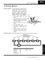
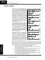
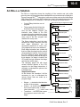
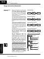
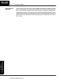
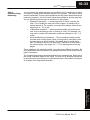
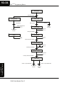
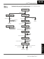
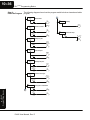
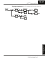
RLL PLUS
Programming Basics
110
In This Chapter. . . .
— Introduction
— An Example Machine
— An RLL Solution
— An RLL PLUS Solution
— Stage Instruction Execution
— Activating Stages
— Using Outputs in Stages
— Using Timers and Counters in Stages
— Using Data Instructions in Stages
— Using Comparative Contacts in Stages
— Parallel Branching Concepts
— Unusual Operations in Stages
— Two Ways to View RLL PLUS Programs
— Designing a Program Using RLL PLUS Instructions
10--2
RLL PLUS Programming Basics
Introduction
If you’ve ever been around some really accomplished RLL programmers you have
probably been amazed at how easily they seem to be able to create programs of
incredible complexity. Well, not everyone has years of experience in programming
PLCs. Because of this the DL330P CPU has RLL PLUS instructions that make it
considerably easier to design and create programming solutions. These instructions
are especially useful to those of you who aren’t that familiar with the interlocking
concepts commonly used in RLL programs.
You can still use the normal instructions you’ve already seen, plus you only have to
become familiar with a few new instructions that help you organize your program into
manageable pieces.
This programming method is similar to Sequential Function Chart programming and
literally allows you to design a flowchart of the program operation sequence and load
it into the CPU! You can expect to see several benefits by using this method.
S Considerably reduced program design time. We’ve seen many, many
cases where these few instructions have cut program design time by
well over 50%.
S Shorter, more simple programs. Later in this chapter we’ll show you why
your programs sometimes end up being a lot larger than you first
anticipated. The RLL PLUS instructions can help make your programs
simple for everyone to understand.
S Easier program troubleshooting. How many times have you tried to
troubleshoot or modify a program that was written by someone else? If
you’ve done this very often you know it’s not an easy task. This chapter
will show you a few instructions that will also help with this problem as
well.
The following paragraphs discuss several RLL PLUS programming concepts. We’ll
use a simple example to show you how to use the various types of instructions. Also,
we’ll show you the equivalent program without RLL PLUS instructions to give you an
idea of the differences between the two approaches.
RLLPLUS
Programming Basics
NOTE: The DL330P has several instructions that do not operate quite the same as
the equivalent instructions in the DL330 or DL340. If you want to take advantage of
the benefits associated with the RLL PLUS instructions, make sure you also take time
to review Chapter 12. This chapter discusses the instructions that are unique or
different with the DL330P CPU.
DL305 User Manual, Rev. D
10--3
RLL PLUS Programming Basics
An Example Machine
Machine Operation
Most any application can be described as
a sequence of events. The PLC program
merely makes sure the events are
completed in a specific order. Not only
does the program control normal
operation, but it also has to allow for
machine failures and emergency
conditions. Consider a simple example.
1. The operator presses the start
switch.
2. The machine checks for a part. If the
part is present, the process
continues. If not, the conveyor moves
until a part is present.
3. The part is locked in place with a
clamp.
4. The press stamps the part.
5. The clamp is unlocked and the
finished piece is moved out of the
press.
6. The process stops if the machine is in
one-cycle mode, or the process
continues if automatic mode is
selected.
On/Off
Switch
Press Arm
Part
Part
Detection
Sensor
Clamp
Machine Flowchart The following diagram provides a flowchart of this operations sequence.
The flowchart
breaks the program
into logical steps
Wait for
Start
Step 1
One
Cycle
Check for
Part
Lock the
clamp
Press the
Part
Unlock
clamp
Move
Conveyor
Step 2
Step 3
Step 4
Step 5
Step 6
Continuous
Check
Mode
Inputs
Start Switch
Part Present
Part Locked
Part Unlocked
Lower Limit
Upper Limit
Conveyor Indexed
One-Cycle Switch
Outputs
000
001
002
003
004
005
006
007
Clamp
Press
Conveyor
020
021
022
DL305 User Manual, Rev. D
RLLPLUS
Programming Basics
Step 7
10--4
RLL PLUS Programming Basics
An RLL Solution
RLLPLUS
Programming Basics
Why is RLL so popular? Simple. Before
the PLC arrived control problems were
generally solved with hardwired relays
and switches. About 30 years ago people
started experimenting with a way to
make quick and easy changes without
changing the actual panel wiring. Thus,
the PLC was born. Since the people
developing and using this new
technology were familiar with the relay
and switch solution, it made sense to
have this new technology emulate
something that was familiar to them.
That’s why RLL programs emulate a
relay panel solution.
When you supply power to a relay panel
the combination of contact and coil status
determines what actions take place.
Since the RLL program emulates the
relay panel solution, the entire program
is scanned left-to-right, top-to-bottom.
The program executes the operations
sequence when a certain combination of
contacts are activated. This process is
known as interlocking.
Since many PLCs do not have
instructions to help manage the
operations sequence, the programmer
has to make sure the program carries out
the correct sequence by adding the
required interlocks. One great thing
about the RLL solution is the individual
rungs are easy to understand. By
examining the contacts you can easily
determine if the output will be on or off.
Executes all rungs Left to Right, Top to bottom
Run
1 Cycle
Stop
RUN
OUT
160
163
011
160
Start
000
RUN
Part
Present
160
001
MCS
Part
Unlocked
Release
Clamp
003
162
Clamp
OUT
020
Clamp
020
Press
Lower
Limit
Index
Conveyor
Press
Complete
OUT
004
006
161
021
Press
Complete
161
Part
Locked
Lower
Limit
Press
Complete
002
004
161
Press
OUT
021
Press
021
Press
Complete
Upper
Limit
Release
Clamp
OUT
161
005
162
MCR
Press
Complete
161
Run
160
Part
Index
Unlocked Conveyor
003
Part
Present
006
Conveyor
OUT
022
001
1 Cycle
Index
Conveyor
007
006
1 Cycle
OUT
163
-- Interlock
Many accomplished RLL programmers use things such as Master Control Relays
and Subroutines to reduce the amount of interlocking required. However, these
instructions can sometimes make the program more difficult to understand. There
are several things you should notice about our simple press program.
S Most all rungs use some amount of interlocking.
S The number of interlocks is usually proportional to the number of tasks
in the operations sequence.
S Most of the instructions are devoted to processing the interlocks. (Plus,
since the program is larger, it takes more time to process.)
S It usually requires several attempts until a program is designed that is
not susceptible to inadvertent activation and deactivation.
S The program can be difficult to debug if you do not have a considerable
amount of RLL programming experience.
DL305 User Manual, Rev. D
RLL PLUS Programming Basics
10--5
An RLL PLUS Solution
The RLL PLUS instructions keep the simplicity of the contacts and coils while
removing some of the problems associated with the enormous amount of interlocks.
There are several RLL PLUS instructions, but the most often used are the Initial Stage
(ISG), Stage (SG), and Jump (JMP) instructions. Here’s the example press program
created using RLL PLUS instructions. There are two things you should notice.
Control Relay interlocks are not
required.
S The program directly follows the
flowchart of the press operation.
How can this happen? Simple. The
interlocks were added to the RLL
program to keep the outputs from coming
on at the improper time. This is because
every rung of the RLL program was
examined on every scan.
The Stage instructions (and the logic
between the Stage instruction and the
next stage instruction) are not
necessarily examined on every scan.
Only stages that are on are examined.
Each stage instruction has a status bit
that is on when the stage is active, and off
when the stage is inactive. On every scan
the CPU examines which stage status
bits are on and only examines the logic in
those stages. If a stage is inactive, the
CPU skips the logic between that stage
and the next active stage.
The following pages will talk about
several different aspects of the CPU
execution for the Stage Instructions. It
will help to understand the pieces of an
individual stage.
Stage Nomenclature
As we discuss the examples it will be
necessary for you to understand the
various pieces that can make up a
program stage.
S
S
S
Stages — a instruction that denotes
a piece of the program
Actions— an event in the program,
such as an output, jump, or some
other instruction.
Transitions — the event that causes
the program to move to the next
stage.
ISG
Wait for start
S000
Start
S1
JMP
000
SG
Check for a part
S001
Part
Present
S2
JMP
001
Part
Present
S5
JMP
001
SG
Lock the clamp
S002
Part
Locked
Clamp
SET
020
S4
JMP
002
SG
Press the part
S003
Press
Down
021
Lower
Limit
S4
JMP
004
SG
Unlock the clamp
S004
Top
Limit
Clamp
RST
020
005
Part
Unlocked
S5
JMP
003
SG
Index the conveyor
S005
Move
Conveyor
022
Conveyor
Moved
S6
JMP
006
SG
One cycle or automatic?
S006
One
Cycle
S0
JMP
007
One
Cycle
007
DL305 User Manual, Rev. D
S1
JMP
RLLPLUS
Programming Basics
S
Only executes logic in stages that are active
10--6
RLL PLUS Programming Basics
Stage Instruction Execution
Stage Instruction
Numbering
Stages are numbered in octal, so you
can’t have any stages with the numbers 8
or 9 in them. Notice the stages skipped
from 7 to 10 since the numbers 8 and 9
are not used. There are 128 (decimal)
stages available in the DL330P CPU,
numbered 0 through 177.
Since each stage has a unique status bit,
you cannot have stages with the same
address number. For example, since the
example program already has a Stage1,
we wouldn’t want to use that number
again.
There’s another advantage to having a
status bit for each stage. This allows you
to skip stage numbers as necessary. This
is a good practice to follow because it
makes it easier to insert stages later
without affecting the appearance of the
program flow.
The stage numbers do not necessarily
have to be numbered sequentially, but it
can be extremely helpful to use
sequential numbers if you are working
with large programs.
Also, the stages do not have to be
entered
sequentially
with
the
programming device. For example, you
could have Stage 100 be the first entry in
the program. This is not a good
programming practice, but since the
CPU looks at the active status bits to
determine which stages to execute, it
doesn’t care where the stages are
physically located in the program.
Octal Numbering
SG
S007
SG
S008
No Duplicate Numbers
SG
S001
SG
S001
RLLPLUS
Programming Basics
The section on Designing an RLL PLUS
Program at the end of this chapter
provides guidelines for assigning
numbers to the stage instructions.
DL305 User Manual, Rev. D
SG
S002
Skip Numbers if Necessary
SG
S010
SG
S020
SG
S030
Non-sequential Numbering
SG
S012
SG
S001
SG
S020
Only executes logic in stages that are active
SG
Press the part
S003
Press
Down
021
Lower
Limit
S4
JMP
004
ISG
Wait for start
S000
Start
NOTE: Remember, machines do break.
We recommend you use numbering that
matches the machine flowchart. Also, we
recommend you enter the program in the
same order whenever possible. This will
make troubleshooting much easier.
SG
S010
S1
JMP
000
SG
Check for a part
S001
Part
Present
S2
JMP
001
Part
Present
001
S5
JMP
RLL PLUS Programming Basics
A Few
Simple Rules for
Execution
10--7
Since the CPU will only examine the logic in those stages that are active, it is
important you understand how stages can be turned on and off. There are a few
simple rules that dictate how this works. This may seem like quite a few things to
remember, but it’s really pretty simple. We’ll show examples in the following pages
that show how each of these rules apply to the program execution.
1. Only active stages are executed. If a stage is inactive, the CPU skips the
logic between that stage and the next active stage.
2. You can turn stages on by the following methods.
2.a Initial Stages are automatically turned on when the CPU transitions
from Program Mode to Run Mode.
2.b A stage can be turned on when the program “jumps” from stage to stage
with the Jump (JMP) instruction.
2.c You can use the SET instruction to set a stage status bit just like you
would SET an output.
2.d A stage can be turned on when the program has power flow between
two stages that are tied together by a single transition element.
3. You can turn stages off by the following methods.
3.a An active stage is automatically turned off if the program jumps from the
active stage to another stage.
3.b You can use the Reset (RST) instruction to turn off a stage just like you
use Reset to turn off an output point.
3.c The current stage is automatically turned off if the program has power
flow between the current stage and the next stage.
RLLPLUS
Programming Basics
DL305 User Manual, Rev. D
10--8
RLL PLUS Programming Basics
Activating Stages
Using Initial Stages
Any initial stages (ISG instructions) are
automatically turned on when the CPU
goes from Program Mode to Run Mode.
For example, when the CPU executing
our example program enters Run Mode,
the Initial Stage (ISG 000) will be turned
on automatically. The other stages are
off, so the CPU only scans the portion of
the program associated with ISG 000.
Since there’s only one rung in Stage 0,
the CPU continually monitors the start
switch. Nothing else will happen until the
start switch is pressed.
Only executes logic in stages that are active
ISG
Wait for start
S000
Start
S1
JMP
000
SG
Check for a part
S001
Part
Present
S2
JMP
001
Part
Present
S5
JMP
001
RLLPLUS
Programming Basics
Although it is unusual, there may be times when you need more than one initial
stage. There is nothing at all wrong with this. If your application has a need for more
than one starting point, you can use more than one initial stage. For example, if you
had three initial stages, then those three stages would all be active when the CPU
entered the Run Mode.
DL305 User Manual, Rev. D
RLL PLUS Programming Basics
Using Jump
Instructions
When the operator presses the start
switch input 000 comes on. When 000
comes on the CPU executes the Jump
instruction and “jumps” to Stage 1.
Now the CPU only scans Stage 1. Stage
0 is no longer scanned after the program
jumped to stage 1. This means the Jump
instruction did two things.
S It activated the destination stage. In
this case, it activated stage 1.
S It deactivated the stage it came
from, which was stage 0 in this
case.
So, you can jump to a stage to turn it on,
and when you jump from a stage it turns
off.
10--9
Only executes logic in stages that are active
ISG
Wait for start
S000
Start
S1
JMP
000
SG
Check for a part
S001
Part
Present
S2
JMP
001
Part
Present
S5
JMP
001
SG
Lock the clamp
S002
Part
Locked
Clamp
SET
020
S3
JMP
002
This example only shows an action that initiates a jump to one destination. You can
use several jumps ORed together if necessary. Examples of this will be shown later.
Only executes logic in stages that are active
There’s also another type of Jump
instruction called a Not Jump. This
ISG
Wait for start
S000
instruction only works if the input
conditions are not true, whereas the
Start
S1
JMP
regular JMP instruction only works if the
000
input conditions are true.
SG
Check for a part
S001
In the previous example we examined a
Part
single contact to determine which part of
Present
S2
JMP
the program to jump to next. If the part is
001
present (001 closed), the program jumps
S5
NJMP
to Stage 2. If a part is not present (001
open), the program jumped to Stage 5.
SG
We could have used a single contact and
Lock the clamp
S002
the NJMP instruction.
Clamp
The program example to the right shows
SET
020
Part
how the NJMP instruction would be used
Locked
S3
JMP
in this situation. Notice there is one less
002
instruction required in this example
compared to the previous one.
DL305 User Manual, Rev. D
RLLPLUS
Programming Basics
NOTE: We strongly recommend you avoid using the NJMP instruction. This is
because program debugging can become more difficult, especially for those who
are not so familiar with structured programming concepts.
10--10
RLL PLUS Programming Basics
Using Set
Instructions with
Stages
When you examine the instruction set
more carefully you’ll notice the DL330P
CPU offers a Set (SET) instruction that
works similarly to a latching operation.
For example, you could use a SET
instruction to latch an output point. The
output point can then be unlatched with
the Reset (RST) instruction.
You can also use a SET instruction to turn
on a stage. To show how this works,
we’re going to add a stage to the
program. You may have noticed the
original flowchart did not contain a stop
switch. Well, we don’t want to make
these little widgets forever, so we’re
adding Stage 150, which monitors for a
stop switch. (This is also a good example
of how you can skip stage numbers.)
Notice we added a SET instruction in the
first stage. Now when the start switch is
pressed, two stages will be activated.
The CPU examines Stage 1, which
monitors for a part, and it also examines
Stage 150, which monitors the stop
switch.
Only executes logic in stages that are active
ISG
Wait for start
S000
Start
S0
JMP
000
SG
S150
SET
Check for a part
S001
Part
Present
S2
JMP
001
Part
Present
S5
JMP
001
SG
Lock the clamp
S002
Part
Locked
Clamp
SET
020
S3
JMP
002
SG
Monitor for stop
S150
Stop
020 -- 022
RST
010
S0 -- S6
RST
RLLPLUS
Programming Basics
S0
JMP
We did not absolutely have to use a SET instruction in the example. We could have
used a Jump, since you can jump to more than one stage. We just used a SET to
show how it works.
If you examine Stage 150, you’ll notice we do three things when the stop switch is
pressed.
S The RST 020 -- 022 instruction makes sure all the outputs are turned off.
(We’ll discuss this in more detail in the next section.)
S The RST S0--S6 instruction resets (turns off) stages 0 through 6. We
reset the entire range so that we guarantee we can stop the press no
matter which stage is currently executing. Notice we reset stages that
were not necessarily turned on with the SET instruction. The Reset
(RST) instruction can be used to turn off stages, no matter how they
were turned on. This is especially handy in larger, more complex
programs.
S The program jumps back to Stage 0 and starts over again. Note, just
because Stage 0 is an initial stage does not mean it can only be active
at a transition to Run Mode. You can return to an Initial Stage at any
time. It’s just the CPU automatically activates Initial Stages at the Run
Mode transition.
DL305 User Manual, Rev. D
RLL PLUS Programming Basics
Power Flow
Transitions
You do not always have to use a Jump
instruction to move from stage to stage. If
you only move to one stage, instead of
multiple stages, you can use what it is
called a power flow transition. For
example, we used Jump instructions in
our sample program. For those stages
that did not have multiple transition
possibilities, we could have just used
power flow transitions.
Look at Stage 2. Notice how the
transition contact, 002 now is directly
connected to the next stage, Stage 3.
You can only do this if you are moving
from one stage to one other stage.
If you examine Stage 1, you’ll notice we
have to use the Jump instructions
because the program can transition to
more than one stage.
10--11
Only executes logic in stages that are active
ISG
Wait for start
S000
Start
S1
JMP
000
SG
S150
SET
Check for a part
S001
Part
Present
S2
JMP
001
Part
Present
S5
JMP
001
SG
Lock the clamp
S002
Part
Locked
Clamp
SET
020
002
SG
Press the part
S003
Press
Down
021
Lower
Limit
004
NOTE: We suggest you use Jump Instructions instead of power flow transitions.
This is because we’ve seen many cases where we had to come back and add things
to the program. If you used Jumps from the beginning, you only have to add another
Jump instruction. If you used power flow transitions, the program edits can take a
little longer.
RLLPLUS
Programming Basics
DL305 User Manual, Rev. D
10--12
RLL PLUS Programming Basics
Using Outputs in Stages
Setting Outputs
with the SET
Instruction
Since the CPU only examines the logic in stages that are on, you have a lot more
flexibility in how you use outputs with the RLL PLUS instructions. Also, you don’t have
to worry about adding several permissive contacts to keep the output from coming
on at an inappropriate time. (If the stage is not on,the CPU doesn’t even scan the
stage, so the output can’t possibly be turned on by the logic in that stage.)
If you examine Stage 2, you’ll notice we
use a SET instruction to clamp the part in
ISG
Wait for start
S000
place. Why a set? Simple. If we used a
regular output the clamp will be
Start
S1
JMP
deactivated
when
the
program
000
S150
transitions to Stage 3. Remember, when
SET
you leave a stage the CPU no longer
SG
Check for a part
S001
scans that stage until it is turned on
Part
again. So if we had used a regular OUT
S2
Present
JMP
instruction, the CPU would have
001
automatically turned off the output, which
Part
S5
Present
would have unclamped the part.
JMP
001
The first example shows the program
SG
execution in Stage 2. The second
Lock the clamp
S002
example shows what happens on the
Clamp
next scan after the part is locked. Notice
SET
020
the clamp output is still on even though
Part
Locked
S3
the CPU is not scanning this portion of
JMP
002
the program. This is why we use the SET
instruction in this case. We want the
clamp to stay on while the press
completes the cycle.
Next Scan after part is locked
The clamp will stay on until the program
SG
enters Stage 4. Stage 4 unlocks the part
Lock the clamp
S002
by resetting output 020 when the press
Clamp
returns to the top limit.
SET
Part
Locked
020
S3
JMP
002
SG
Press the part
S003
Press
Down
021
Lower
Limit
S4
JMP
RLLPLUS
Programming Basics
004
SG
Unlock the clamp
S004
Top
Limit
005
Part
Unlocked
003
DL305 User Manual, Rev. D
Clamp
RST
020
S5
JMP
RLL PLUS Programming Basics
Using the OUT
Instruction
One other benefit with RLL PLUS is the
ability to use the same output in multiple
places. Instead of using the SET
instruction in Stage 2, we could have just
put the clamp output, 020, in all the
stages where we wanted the part to
remain clamped.
If you examine Stage 2 you’ll notice
output 020 is on because the stage is
active. The next example shows what
happens after the part is locked in place.
The program moves to Stage 3 from
Stage 2. Notice output 020 is now off in
Stage 2. However, since we included the
same clamp output in Stage 3, the part
remains clamped in place.
The clamp will automatically turn off
when the program enters Stage 4. Notice
Stage 4 does not have to have any kind of
Reset instruction, since the output is
automatically turned off when the
program exits Stage 3.
The concept of automatically turning off
the outputs sometimes confuses many
people. However, the CPU just uses a
very simple algorithm to determine if the
output should be turned off. The following
diagram shows how this algorithm
works.
ISG
Wait for start
S000
Start
S1
JMP
000
SG
10--13
S150
SET
Check for a part
S001
Part
Present
S2
JMP
001
Part
Present
S5
JMP
001
SG
Lock the clamp
S002
Clamp
OUT
020
S3
JMP
Part
Locked
002
Next Scan after part is locked
SG
Lock the clamp
S002
Clamp
OUT
020
S3
JMP
Part
Locked
002
SG
Press the part
S003
Press
Down
021
Clamp
OUT
020
Lower
Limit
Stage=On
No
S4
JMP
004
SG
Yes
Any outputs
on last
scan?
No
Unlock the clamp
S004
Top
Limit
Part
Unlocked
005
003
S5
JMP
Yes
Examine Logic,
AND results
with 0
Skip to next
active stage
DL305 User Manual, Rev. D
RLLPLUS
Programming Basics
Execute
Logic
10--14
RLL PLUS Programming Basics
Latching Outputs
with Stages
There’s one more way to control outputs
with the Stage instructions. You may
recall once a stage is turned on, you can
only turn it off by resetting it, or by having
a transition from it, either by a Jump or a
power flow.
What happens if you have a stage that
does not have any kind of transition?
What if it doesn’t have a Jump instruction
or any other kind of transition contact
leading to another stage? Simple. The
stage will stay on until it is reset by some
other part of the program that uses a
Reset instruction.
This makes it easy to use a stage without
a transition to latch an output. For
example, if you examine Stage 2 you’ll
notice we’ve now changed this part of the
program again. Now this stage sets
Stage 140,which will be used to control
the clamp.
Notice Stage 140 does not have any type
of transition. The only way to turn off the
clamp is to Reset Stage 140. This
instruction has now been included in
Stage 4. So, after the program transitions
to Stage 4, the Reset instruction will turn
off Stage 140.
ISG
Wait for start
S000
Start
S1
JMP
000
SG
S150
SET
Check for a part
S001
Part
Present
S2
JMP
001
Part
Present
S5
JMP
001
SG
Lock the Clamp
S002
Part
Locked
SET
S140
S3
JMP
002
Next Scan after part is locked
SG
Lock the clamp
S002
Part
Locked
SET
S140
S3
JMP
002
SG
Press the part
S003
Press
Down
021
Lower
Limit
S4
JMP
004
SG
Unlock the clamp
S004
Top
Limit
Clamp
RST
S140
005
Part
Unlocked
S5
JMP
003
RLLPLUS
Programming Basics
SG
S140
Clamp
Clamp
020
DL305 User Manual, Rev. D
RLL PLUS Programming Basics
10--15
Using Timers and Counters in Stages
Time Based
Transitions
Up to this point we’ve been using certain
events that triggered the transition from
stage to stage. There will probably be
many cases where the transition should
be related to a timer value. For example,
if you know the speed of the conveyor
you could use a timer to control the
conveyor movement.
If we used this approach we would
modify Stage 5 as shown. Notice the
timer does not have a preset value. The
timer begins incrementing as soon as it
becomes active. Since the timer does not
have a preset value, you do not have a
timer contact, so you have to use a
comparative instruction.
In the example shown, the conveyor will
be turned on for 5 seconds and then the
program will jump to the next stage.
Only executes logic in stages that are active
SG
Unlock the clamp
S004
Top
Limit
Clamp
RST
020
005
Part
Unlocked
S5
JMP
003
SG
Index the conveyor
S005
Move
Conveyor
022
TMR
T600 50
SG
T600
S6
JMP
One cycle or automatic?
S006
One
Cycle
007
One
Cycle
S0
JMP
S1
JMP
007
RLLPLUS
Programming Basics
DL305 User Manual, Rev. D
10--16
RLL PLUS Programming Basics
There will also be times when you need
to count things that happen throughout
the process. For example, you may want
to know the number of parts produced
during any given shift, or you may know
the presses generally require some type
of maintenance after a certain number of
cycles.
If we wanted to count the number of
widgets made on our simple press, we
could just add a counter to Stage 4 to
monitor how many times the press is
used. We’re also going to use the counter
as an automatic shutdown when the
press has made 5000 parts so we’ve
added a new rung in Stage 150 to
perform the shutdown operation.
Notice the counter does not have a reset
leg. This is true only when you use a
counter with the DL330P. (The other
CPUs have counters with reset legs.)
Even though this counter does not have a
reset leg, it can be reset with a Reset
instruction. This works just like an output
reset, so you could place this reset
wherever it is appropriate. We’ve placed
it in Stage 150 for this example.
When the parts count reaches 5000, the
program will finish the current cycle,
reset the part counter, and jump to Stage
0 to wait for another start cycle. You may
notice we added an additional input, 006.
This is what allows the program to finish
the current cycle. (You may recall 006
only came on after the part was unlocked
and the conveyor was indexed.)
RLLPLUS
Programming Basics
Using Counters
DL305 User Manual, Rev. D
SG
Lock the clamp
S002
SET
S150
S3
JMP
Part
Locked
002
SG
Press the part
S003
Press
Down
021
Lower
Limit
CNT
C600
004
S4
JMP
SG
Monitor for stop
S150
Stop
020 -- 022
RST
010
S0 -- S6
RST
S0
JMP
Parts Count
C600 K5000
Index
Conveyor
006
C600
RST
S0 -- S6
RST
S0
JMP
RLL PLUS Programming Basics
10--17
Using Data Instructions in Stages
Even though there are a few differences
in the way some of the instructions
operate between the various CPUs,
there are many of the normal instructions
that can be used inside an individual
stage. For example, you may need to
load data into the accumulator to perform
some type of math, or, you may need to
store values into register locations.
If you examine Stage 3, you’ll notice
we’ve added a couple of instructions.
These instructions store the current parts
count in a register.
Now the CPU will take the current parts
count, stored in R600, and load it into the
accumulator with the DSTR instruction.
Then this 4-digit BCD count will be
moved to R400 with the DOUT
instruction.
This is just one example of how you can
use the various types of data
instructions. There are many other
possibilities. Just remember, if the stage
is active, the instructions can be
executed. If the stage isn’t active, the
instructions will not even be examined.
SG
Lock the clamp
S0002
SET
S150
S3
JMP
Part
Locked
002
SG
Press the part
S0003
Press
Down
021
Lower
Limit
CNT
C600
004
DSTR
F50
R600
DOUT
F60
R400
S4
JMP
SG
Monitor for stop
S150
Stop
020 -- 021
RST
010
S0 -- S6
RST
S0
JMP
Parts Count
C600 5000
Index
Conveyor
006
CT0
RST
S0 -- S6
RST
S0
JMP
RLLPLUS
Programming Basics
DL305 User Manual, Rev. D
10--18
RLL PLUS Programming Basics
RLLPLUS
Programming Basics
Using Comparative Contacts in Stages
You may recall you had to use a
comparative instruction with the timers
and counters. The DL330P provides
several comparative contacts that are
very useful. You can use these contacts
to examine the relationship between a
counter or timer value and a constant or
register value.
For example, let’s assume the pressed
widgets move off the conveyor into a
holding bin. The bin can only hold 1000
widgets, so we’ll add another counter,
C601, to note how many widgets are in
the bin. Also, we want to use different
colored lights mounted on top of the
press to alert a forklift driver the bin
needs to be carried to the next operation.
We’ll use the following indicators.
Indicator Meaning Address Stage
Green
OK
040
21
Yellow
Soon
041
22
Red
Urgent
042
23
Reset
Emptied 030
Notice we’ve added a few more stages to
monitor this condition. For this example,
assume the press has made 750
widgets. This means the Yellow indicator
(Stage 22) should be active.
We also need a way to reset the bin
counter whenever the forklift driver
empties the bin. If you examine Stage 21
through Stage 23, you’ll notice we reset
the bin counter whenever the bin reset
(030) is active.
This example doesn’t show it, but you
would also have to make some changes
to other parts of the program. For
example, you’d need to modify the Stop
Stage to shut off these stages when the
machine was stopped.
SG
Press the part
S0003
Press
Down
021
Lower
Limit
CNT
C600
004
DSTR
F50
R600
DOUT
F60
R400
CNT
Bin counter
C601
S4
JMP
SG
Monitor lights for forklift
S0020
R601 K499
S21
SET
S22
RST
S23
RST
R601 500
R601
K899
S22
SET
S21
RST
R601 K900
S23
SET
S22
RST
SG
Bin level OK
S0021
040
OUT
Bin
Emptied
C601
RST
030
SG
Empty bin soon
S0022
041
OUT
Bin
Emptied
C601
RST
030
SG
Empty bin now
S0023
042
OUT
Bin
Emptied
030
DL305 User Manual, Rev. D
C601
RST
RLL PLUS Programming Basics
10--19
Parallel Branching Concepts
Branching
Methods
As you examined some of the previous examples you saw we could have more than
one stage being processed on any given scan. The CPU scanned the first active
stage and then moved on to the next active stage, skipping any inactive stages in
between. For some complex applications, you can easily have as many parallel
paths as necessary. This is often called branching or divergence.
There are a couple of approaches you can take when you want to turn on more than
one stage. The diagrams shown don’t necessarily apply to our press example, but
instead show the various approaches.
Only executes logic in stages that are active
In this example, you use one transition
contact to activate several stages.
ISG
Wait for start
S000
S The SET instruction sets a range of
Start
S20 -- S30
stages. These stages would remain
SET
on until they were reset, or, until
000
S2
any transition instructions contained
JMP
within the stages were executed.
S50
JMP
S There are two Jump instructions,
both activating different stages.
In this example, notice the stage that gets
activated depends on an extra condition.
For example, if the machine was capable
of producing three different patterns,
there may be a section of program for
each pattern.
There are other types of contacts that
can be used. For example, you may
recall we used Comparative contacts in
some earlier examples.
Notice we had to repeat the start switch in
a separate rung each time. At first glance
you would think you could simply have
one Start switch contact and OR the
remaining switches. The DL305 CPUs
do support midline outputs (which is what
this is called), but only in an AND
situation.
Only executes logic in stages that are active
ISG
Wait for start
S000
Start
Pattern 1
000
020
Start
Pattern 2
000
021
Start
Pattern 3
000
022
ISG
S0000
S100
JMP
S200
JMP
S300
JMP
Wait for start
Start
Pattern 1
000
020
Pattern 2
S100
JMP
S200
JMP
021
Pattern 3
S300
JMP
022
ISG
S000
S100
SET
000
001
S200
JMP
002
S300
JMP
000
023
DL305 User Manual, Rev. D
RLLPLUS
Programming Basics
You can also use midline outputs to
control branching conditions. Here’s an
example of branching instructions that
follow the guidelines for midline outputs.
(This example is not for the press
program, but merely shows how the
midline outputs would appear.)
10--20
RLL PLUS Programming Basics
There are many times you have to bring parallel branches back together at some
point in the program. You may recall the stages have status bits associated with
them. You can use this status bit as a contact to easily converge the parallel paths.
To illustrate this method, we’re going to use a simple press with two stations. Now a
widget must get pressed at each station before it is a finished product. Since there
are two stations, we must make sure both operations are complete before we move
the conveyor.
RLLPLUS
Programming Basics
Joining Parallel
Branches
DL305 User Manual, Rev. D
RLL PLUS Programming Basics
10--21
Here’s a flowchart that describes the two-station press. Please note we’ve changed
some of the stage numbers, input numbers, and output numbers, so they won’t
necessarily match the previous examples.
Check for
Stop
Stage150
Reset all stages
Jump to Start
Check for
Parts in
A&B
Stage 10
Lock the
clamp
Press the
Part
Unlock
clamp
Wait for
Station B
Move
Conveyor
Check
Mode
A Stage 20
Stage 21
Stage 22
Stage 23
Stage 40
Stage 50
Station A
Wait for
Start
Stage 0
No Part in A
Station B
Lock the
clamp
Press the
Part
Unlock
clamp
Station B
Finished
B Stage 30
Stage 31
Stage 32
Stage 33
Program must
converge into
a single path
again
No Part in B
One
Cycle
Continuous
You’ve already seen how the basic sequence of operations was executed. so we’re
only going to show the portions of the program that describe how the branches are
joined together.
RLLPLUS
Programming Basics
DL305 User Manual, Rev. D
10--22
RLL PLUS Programming Basics
Using Stage Bits
as Contacts
If you examine the flowchart you’ll notice
once the part is unclamped in station B,
the program transitions to Stage 33
which indicates Station B is complete.
If you look at that portion of the program
shown here, you’ll notice there are no
other instructions or actions that take
place in this stage. This is why we call it a
“dummy” stage. We’re just going to use
the status of the stage bit associated with
this dummy stage as a contact elsewhere
in the program to indicate station B is
finished.
You may be wondering how we can turn
off this stage. Since it does not have any
type of jump or power flow transition, the
only other option is to Reset the stage.
We’ll do this later in the program.
Station B
SG
Lock the clamp
S030
Clamp
SET
020
S31
JMP
Part
Locked
023
SG
Press the part
S031
Press
Down
021
Lower
Limit
S32
JMP
024
SG
Unlock the clamp
S031
Top
Limit
Clamp
RST
020
025
Part
Unlocked
S33
JMP
023
SG
S0033
Station B Finished
Check for
Stop
Stage 150
Reset all stages
Jump to Start
Station A
Wait for
Start
Stage 0
Check for
Parts in
A&B
Stage 10
Lock the
clamp
Press the
Part
Unlock
clamp
Wait for
Station B
Move
Conveyor
Check
Mode
A Stage 20
Stage 21
Stage 22
Stage 23
Stage 40
Stage 50
No Part in A
RLLPLUS
Programming Basics
Station B
Lock the
clamp
Press the
Part
Unlock
clamp
Station B
Finished
B Stage 30
Stage 31
Stage 32
Stage 33
No Part in B
One
Cycle
Continuous
DL305 User Manual, Rev. D
Program must
converge into
a single path
again
RLL PLUS Programming Basics
Stage Contact
Example
Since each stage has a status bit that is
either on or off, you can use this bit as a
contact in the program. If you examine
Stage 23 you’ll notice we’ve used a
contact labeled S33. This contact
reflects the status of Stage 33, which
indicated Station B was finished.
When S33 is on, the contact labeled S33
is also on and the program will transition
to Stage 40. In Stage 40 we use a reset
instruction to reset Stage 33 before we
move the conveyor.
10--23
Only executes logic in stages that are active
Station A
SG
Clamp the part
S020
Part
Locked
Clamp
SET
020
S21
JMP
002
SG
Press the part
S021
Press
Down
021
Lower
Limit
S22
JMP
004
SG
Unlock the clamp
S022
Top
Limit
Clamp
RST
020
005
Part
Unlocked
S23
JMP
003
SG
Wait for Station B to finish
S023
B
Finished
S40
JMP
S33
SG
Index the
conveyor
S040
B
Finished
RST
S33
Conveyor
022
Conveyor
Moved
S50
JMP
006
SG
One cycle or automatic?
S050
One
Cycle
S0
JMP
007
One
Cycle
S10
JMP
007
RLLPLUS
Programming Basics
DL305 User Manual, Rev. D
10--24
RLL PLUS Programming Basics
Unusual Operations in Stages
Using the Same
Output Multiple
Times
Over the last few pages you’ve learned how the CPU executes the Stage
instructions. However, there are a few unusual circumstances that may not work
exactly as the appear.
In the program shown it appears output
021 will be turned on at three separate
SG
times before the program jumps to the
S0010
next stage. However, the only time the
TMR
T600
output actually comes on is when the
final condition has been met.
T600 K100
021
Why? Remember if you use multiple
OUT
outputs in a program, the last rung
021
T600 K200 T600 K500
containing the output controls the status
OUT
that will be written to the module. This is
021
T600 900
no different in a program that uses
OUT
PLUS
instructions.
RLL
Finished
S20
In this example, the last comparison rung
JMP
001
says the output should be off until the
timer value reaches 90 seconds.
RLLPLUS
Programming Basics
In the previous example the same output
was used multiple times in the same
stage. The last use of the output
controlled the status of the output.
There may be occasions when you have
the same output in different stages. Even
though it’s not advisable to do this in
normal RLL programs, this is perfectly
acceptable with a program that uses
RLL PLUS instructions. However, if both
stages are active at the same time, then
the logic in the last stage will control the
status of the output.
In the example shown, if both stages are
active, then the logic in Stage 70 will
control the output status.
DL305 User Manual, Rev. D
SG
S0010
021
OUT
001
S002
JMP
002
SG
S070
021
OUT
010
011
S002
JMP
006
RLL PLUS Programming Basics
Using a Set Out
Reset (SET OUT
RST) Instruction
Output Placement
Many normal RLL programs use
one-shot instructions. In the DL305
instruction set, this instruction is called a
Set Out Reset (SET OUT RST).
In the program shown, input 001 will
trigger the SET OUT RST 160
instruction, which will in turn activate
output 021 for one scan.
However, what happens if 001 stays on
and Stage 10 is activated, deactivated,
and then activated again? At first glance
it appears the one shot only gets
executed one time since 001 stayed on
while Stage 10 was turning on and off. It
doesn’t work this way.
The logic in an inactive stage is not
executed. So even though the stage
became active the SET OUT RST
instruction did not see an off to on
transition, so the instruction is not
executed.
The SET OUT RST instruction will work
in an active stage as long as the input
transitions from off to on while the stage
is active.
Scan N
SG
One Shot is executed
S010
001
160
SET OUT RST
160
021
OUT
Scan N + 10
SG
Stage off,
One Shot is not executed
S0010
001
160
SET OUT RST
160
021
OUT
Scan N + 20
SG
S0010
One shot must see off to on
001
160
SET OUT RST
160
021
OUT
Incorrect Placement
SG
S0010
001
CNT
C600
021
OUT
003
S11
JMP
Correct Placement
SG
S0010
021
OUT
001
CNT
003
DL305 User Manual, Rev. D
C600
S11
JMP
RLLPLUS
Programming Basics
As you’ve seen in some of the previous
examples,
we
always
place
unconditional
outputs
immediately
following the Stage Instructions. There’s
a reason for doing this.
If you look at the example stage shown
here, the output is placed after a counter
box. The DirectSOFT software and the
Handheld Programmer will allow you to
enter this as shown. However, the CPU
will only turn on output 021 when the
counter input 001 is turned on. This is
because the CPU interprets the output as
being tied to the counter input leg instead
of the Stage power rail.
You can easily avoid this problem by
placing any unconditional actions at the
very beginning of the stage. Then, the
output will work the way you expect.
10--25
10--26
RLL PLUS Programming Basics
Two Ways to View RLL PLUS Programs
Throughout the example programs, we’ve consistently shown how the instructions
appear in when viewed as ladder instructions. However, with DirectSOFT, you also
have the capability to view the program as a flowchart. You can even view the
program flowchart (in Stage View) and view the ladder program at the same time
with a split screen feature. The DirectSOFT manual provides detailed information
on how to view the programs in this manner.
DirectSOFT
Stage View
ISG
S0
J
J
SG
Stage
SG
S1
SG
S150
Reference to
a Stage
DirectSOFT
Ladder View
J
SG
S2
S
SG
S140
J
SG
S6
J
SG
S3
J
ISG
S0
R
SG
S140
Transition
Logic
ISG
J
Wait for start
S000
Start
S1
JMP
000
SG
Check for a part
S001
Part
Present
S2
JMP
001
Part
Present
S5
JMP
001
RLLPLUS
Programming Basics
SG
Lock the clamp
S002
Part
Locked
Clamp
SET
020
S4
JMP
002
SG
Press the part
S003
Press
Down
021
Lower
Limit
004
DL305 User Manual, Rev. D
S4
JMP
Jump
S
Set Stage
R
Reset Stage
RLL PLUS Programming Basics
10--27
Designing a Program Using RLL PLUS Instructions
As with most any application problem, a thorough understanding of the tasks
combined with a good plan of execution often results in success. The RLL PLUS
instructions provide an easy way to load the plan of execution directly into the CPU.
The easiest way to make sure you understand the tasks is to make a flowchart. This
is often the most critical part of creating a program that uses RLL PLUS instructions.
There are a few simple steps you can follow to create a detailed flowchart.
1. Create a top-level flowchart.
2. Expand the flowchart by adding things that cause the transitions from step
to step.
3. Add any actions that must occur in each step.
4. Add any conditions that control the actions.
5. Add any special monitoring or alarm steps that must be performed.
6. Assign numbers to the stages (steps).
7. Add the I/O instructions and addresses (input contacts, output coils, jump
instructions, etc.)
8. Enter the program.
Use DirectSOFT to The DirectSOFT programming package allows you to quickly and easily create
programs with RLL PLUS instructions. The software has special features that allow
Save Time
you to create the flowcharts, add the transitions, actions, etc. Even if your programs
are fairly small, DirectSOFT can make the job much easier.
RLLPLUS
Programming Basics
DL305 User Manual, Rev. D
10--28
RLL PLUS Programming Basics
Step 1:
Design a Top-level
Flowchart
There are many different ways to design a flowchart of the application problem, but
there are a few guidelines that will make the job easier.
1. Start with a “top-level” flowchart that breaks the operation sequence into
simple pieces.
2. Each piece of the top-level flowchart should only represent one action.
Resist the temptation to group several operations into one part of the
flowchart.
3. Don’t try to add input or output addresses to the flowchart. Only use words
to describe the things that are taking place.
4. Don’t worry about special conditions, such as stop conditions, alarms, etc
at this point. These will be added later when you fully understand how the
main part of the operations sequence is organized.
You can draw the flowchart horizontally or vertically at any point in the design
process, the choice is yours. Here’s an example top level flowchart for our simple
one-station press.
The flowchart
breaks the program
into logical steps
Wait for
Start
RLLPLUS
Programming Basics
One
Cycle
DL305 User Manual, Rev. D
Check
for Part
Continuous
Check
Mode
Lock
Clamp
Press
Part
Unlock
Clamp
Move
Conveyor
RLL PLUS Programming Basics
Step 2:
Add Flowchart
Transitions
10--29
Once you have designed the basic operating sequence you should determine the
events that cause a transition from step to step. During this phase you may find
things need to be added to the flowchart. All you’re really doing is adding more detail
to the top-level flowchart. Once again, don’t try to use addresses yet. Concentrate on
using words to describe the events taking place. The following flowchart adds the
transition conditions for our one-station press.
Wait for Start
Transition
Symbol
Press Start Switch
Check for Part
Part in place
No Part
Lock the Clamp
Jump to
Move
Conveyor
Clamp Limit Switch
Press the Part
Press Lower Limit Switch
Unlock the Clamp
Unclamp Limit Switch
Move Conveyor
Conveyor Index Limit Switch
Check 1-cycle Switch ON
Jump to Wait
for Start
Check 1-cycle Switch OFF
Jump to
Check for
Part
DL305 User Manual, Rev. D
RLLPLUS
Programming Basics
Check Mode
10--30
RLL PLUS Programming Basics
Step 3:
Add Actions
After you determine the events that cause a transition from step to step you should
add any actions that need to take place during the sequence. Again, don’t try to use
addresses yet. Concentrate on using words to describe the actions taking place. The
following flowchart adds the actions that take place during each part of the program.
Wait for Start
Press Start Switch
Check for Part
Part in place
No Part
Jump to
Move
Conveyor
Lock the Clamp
Clamp On
Clamp Limit Switch
Action
Symbol
Press the Part
Press
Press Lower Limit Switch
Unlock the Clamp
Clamp Off
Unclamp Limit Switch
Move Conveyor
Conveyor On
Conveyor Index Limit Switch
RLLPLUS
Programming Basics
Check Mode
Check 1-cycle Switch ON
Jump to Wait
for Start
DL305 User Manual, Rev. D
Check 1-cycle Switch OFF
Jump to
Check for
Part
RLL PLUS Programming Basics
10--31
Step 4:
Some actions may only take place if certain conditions are met. Examine the
Add Conditions for program carefully to determine any conditions that should be added. The following
flowchart adds any conditions for the actions that take place during each part of the
Actions
program.
Wait for Start
Press Start Switch
Check for Part
Part in place
No Part
Jump to
Move
Conveyor
Lock the Clamp
Clamp On
Clamp Limit Switch
Press the Part
Press
Press Lower Limit Switch
Unlock the Clamp
Press Up
Clamp Off
Unclamp Limit Switch
Move Conveyor
Condition
Symbol
Conveyor On
Conveyor Index Limit Switch
Check Mode
Jump to Wait
for Start
Check 1-cycle Switch OFF
Jump to
Check for
Part
DL305 User Manual, Rev. D
RLLPLUS
Programming Basics
Check 1-cycle Switch ON
10--32
RLL PLUS Programming Basics
Step 5:
Add Alarm or
Monitoring
Operations
Many people are tempted to add alarm or monitoring operations earlier in the
flowchart design process. It is almost always easier to add them last because then
you know how they should affect the main part of the program. The following
flowchart adds an operation that monitors for the conditions that will stop the press.
Wait for Start
Press Start Switch
Check for Part
Monitor for Stop
Stop Switch
Part in place
Reset all Operations
Jump to Wait
for Start
No Part
Jump to
Move
Conveyor
Lock the Clamp
Clamp On
Clamp Limit Switch
Press the Part
Press On
Press Lower Limit Switch
Unlock the Clamp
Press Up
Clamp Off
Unclamp Limit Switch
Move Conveyor
Conveyor On
Conveyor Index Limit Switch
RLLPLUS
Programming Basics
Check Mode
Check 1-cycle Switch ON
Jump to Wait
for Start
DL305 User Manual, Rev. D
Check 1-cycle Switch OFF
Jump to
Check for
Part
RLL PLUS Programming Basics
Step 6:
Determine Stage
Numbering
10--33
You can number the stages any way you would like, but it’s usually best to follow
some type of sequence that matches the flow of the program. This makes it much
easier to understand. There are a few guidelines we have used to determine the best
numbering sequence. You don’t have to follow these guidelines, but they may help.
You can typically find these types of operations in any program.
S Sequential Operations — a certain sequence of events, one after the
other. This is usually the main part of the program. It’s usually best to
number these first. For example, you may want to always number these
stages from 0 -- 127 (octal).
S Independent Operations — these operations usually only perform one
task, such as activating a motor or turning on a horn. For example, you
may want to number all independent operations starting from 130 -- 147
(octal).
S Alarm and Monitoring Operations — These operations usually monitor
the main parts of the program. Since you may want to reset parts of the
program during an alarm condition, it is usually best to number these
last. This way you can use one Reset (RST) instruction to reset almost
the entire program. Use stages 150 -- 177 for alarming and monitoring
stages.
These guidelines are especially helpful if you have many different programs. By
using a standard numbering scheme, you always know where to look for the various
types of operations.
The example shows how we assigned numbers for the example press. Notice we’ve
also made a separate stage for the clamp. This was not an absolute requirement
because there are several ways you could have done this. We just did it to show you
an example of an independent operation.
RLLPLUS
Programming Basics
DL305 User Manual, Rev. D
10--34
RLL PLUS Programming Basics
Initial Stage 0
Wait for Start
Press Start Switch
Stage 1
Check for Part
Stage 150
Monitor for Stop
Stop Switch
Part in place
Reset all Operations
No Part
Jump to
Move
Conveyor
Stage 2
Lock the Clamp
Clamp On
Jump to Wait
for Start
Clamp Limit Switch
Stage 140
Clamp
Stage 3
Press the Part
Clamp
Press On
Press Lower Limit Switch
Stage 4
Unlock the Clamp
Press Up
Clamp Off
Unclamp Limit Switch
Stage 5
Move the Conveyor
Conveyor On
Conveyor Index Limit Switch
Stage 6
Check Mode
RLLPLUS
Programming Basics
Check 1-cycle Switch ON
Jump to Wait
for Start
DL305 User Manual, Rev. D
Check 1-cycle Switch OFF
Jump to
Check for
Part
RLL PLUS Programming Basics
10--35
The final step before you enter the program is to assign the I/O addresses and the
destinations for any Jump, Set, or Reset instructions.
Step 7:
Assign I/O
Addresses
Initial Stage 0
Wait for Start
Press Start Switch
Stage 1
Check for Part
Stage 150
Monitor for Stop
Stop Switch
000
010
Part in place
Reset All Operations
RST
S0 -- S140
Jump to
Wait for Start
001
No Part
Jump to
Move
Conveyor
Stage 2
Lock the Clamp
Clamp Limit Switch
Stage 140
Clamp
002
Clamp
SET
S140
Stage 3
Press the Part
Clamp
OUT
020
Press Lower Limit Switch
004
Press On
OUT
021
Stage 4
Unlock the Clamp
Press Up
Unclamp Limit Switch
005
003
Clamp
RST
S140
Stage 5
Move the Conveyor
006
Conveyor Index Limit Switch
Conveyor
OUT
022
Stage 6
Check Mode
Check 1-cycle Switch OFF
007 Closed
Jump to
Wait for Start
007 Open
Jump to
Check for
Part
DL305 User Manual, Rev. D
RLLPLUS
Programming Basics
Check 1-cycle Switch ON
10--36
RLL PLUS Programming Basics
Step 8:
Enter the Program
The following diagram shows how the program would look when viewed as a ladder
program.
ISG
Start
S1
JMP
000
SG
A
Wait forStart
S000
020
S2
JMP
001
S6
JMP
001
Clamp
SET
S140
S3
JMP
002
Press the part
S003
Press
Down
021
Lower
Limit
S4
JMP
004
Unclamp the part
S004
Top
Limit
Clamp
RST
S140
005
Part
Unlocked
S5
JMP
003
SG
Index the conveyor
S005
Move
Conveyor
022
Conveyor
Moved
S6
JMP
006
SG
RLLPLUS
Programming Basics
A
One cycle or automatic?
S006
One
Cycle
S0
JMP
007
One
Cycle
007
DL305 User Manual, Rev. D
SG
Check for Stop
S150
Stop
010
Clamp the part
S002
Part
Locked
SG
Clamp
OUT
Check for a Part
S001
Part
Present
SG
Clamp
S140
S150
JMP
Part
Present
SG
SG
S1
JMP
S0 -- S140
RST
S000
JMP
RLL PLUS Programming Basics
10--37
This diagram shows how a portion of the program would look when viewed as a
Stage Diagram in DirectSOFT.
Wait forStart
ISG
S0
Check for a Part
J
SG
S1
Clamp the part
J
SG
S2
J
SG
S6
Clamp
S
Press the part
J
Check for Stop
J
SG
S150
J
ISG
S0
R
SG
S140
SG
S140
SG
S3
RLLPLUS
Programming Basics
DL305 User Manual, Rev. D