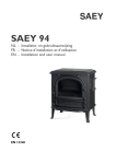
1
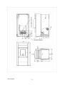
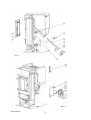
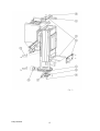
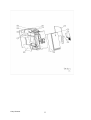
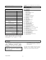
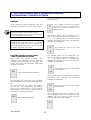
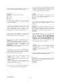
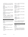
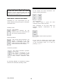
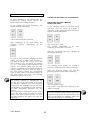
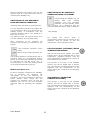
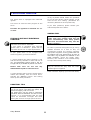
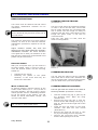
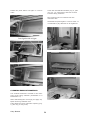
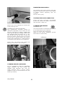
User manual Saey NEEMA
Supply combustion air
Smoke exhaust
Verwarmingssystemen voor
woningen
Saey Neema
2
Fig. 3
Afb. 4
Saey Neema
3
Saey Neema
4
Saey Neema
5
Table of contents
TECHNICAL DATA
9
OVERVIEW OF SPARE PARTS
9
PACKAGING
9
1. IMPORTANT INFORMATION
10
GENERAL WARNING AND SAFETY TIPS
10
2. WHAT ARE PELLETS?
10
PELLET STORAGE
10
3. TECHNOLOGY
10
OPERATING COMFORT - OPERATING SAFETY
11
HIGHEST EFFICIENCY – LOWEST EMISSIONS
11
4. AUTOMATIC SAFETY FUNCTION
11
POWER FAILURE
11
OVERHEATING
11
LOW TEMPERATURE SWITCHING OFF
11
ELECTRICAL CURRENT OVERLOAD PROTECION
11
5. INSTALLATION OF THE FIREPLACE STOVE
12
GENERAL NOTES
12
ESTABLISHING THE FIREPLACE CONNECTION
12
FLOOR PROTECTION
12
SAFE DISTANCES
12
ELECTRICAL CONNECTION
12
COMBUSTION AIR
12
SUPPLY OF EXTERNAL COMBUSTION AIR
13
Saey Neema
6
6. ASSEMBLY OF COVERING, OPTIONS
14
GENERAL
14
ASSEMBLY OF STONE COVERING
14
ASSEMBLY OF CONVECTION FAN (OPTIONAL)
14
7. OPERATION
15
BASIC INSTRUCTIONS
15
CONTROL AND INTERNAL SERVICE MODULE - FUNCTION
15
8. PUTTING THE APPLIANCE IN SERVICE/CONTROL
PROGRAMMING/CONTROL OPTIONS
16
GENERAL
16
PUTTING IN SERVICE THE FIRST TIME/PROGRAM SETTINGS
16
MAIN MENU - OPERATING RANGES
19
TAKING THE APPLIANCE OUT OF OPERATION
20
SWITCHING OFF FROM "MANUAL OPERATION (ON)"
20
SWITCHING OFF THE APPLIANCE FROM AUTOMATIC OPERATION
21
MANUAL AUTOMATIC STOP
21
SWITCHING OFF BY CHANGE OF OPERATING MODE TO STAND-BY
21
PELLET CONTROL (OPTIONAL) ROOM TEMPERATURE SENSOR
21
TELECONTROL (TELEPHONE CONTROL OPTIONAL)
21
9. ELEKTRICAL IGNITION
22
FIRING UP WITHOUT ELECTRICAL IGNITION
22
PRACTICAL TIPS
22
ADDING FUEL
22
10. CLEANING AND MAINTENANCE
23
BASIC INSTRUCTIONS
23
SERVICING HANDLE
23
WOOD AS FERTILIZER
23
CLEANING THE FIRE CUP
23
Saey Neema
7
CLEANING DOOR GLASS
23
CLEANING EXHAUST GAS PIPES
23
CLEANING EXHAUST MANIFOLD
24
CLEANING PELLET CONTAINER
25
INSPECTING DOOR SEALS
25
TESTING FIREPLACE CONNECTION
25
CLEANING AIR SENSOR
25
11. DISRUPTIONS – CAUSES - SOLUTIONS
26
12. ANNEX
28
MENU COMMANDS FOR PROGRAMMING INTERNAL CONTROL
28
LIST OF KEY WORDS, ABBREVIATIONS
29
13. WE GUARANTEE
30
Explanation of symbols
!
important communication
)
practical advice
consult the plan for assistance
Saey Neema
8
requested by the authorities or the chimneysweep.
TECHNICAL DATA
SPARE PARTS LIST
(Fig. 3 – Fig. 7)
(Fig. 1)
TECHNICAL DATA
No.
1
2
3
4
5
6
7
8
9
10
11
20
21
22
23
30
31
32
33
34
35
36
37
38
39
40
41
42
43
44
45
46
47
48
49
50
Size (mm) and weight (kg)
Height
1031
Width
520
Depth
626
Weight without casing
Weight with steel front
Weight with stone covering
Smoke pipe outlet diameter
Heat output range
Space heating power (m³)
depending on the building
insulation
Fuel consumption
Pellet container capacity
Mains connection
Average electronic power
consumption
127
250
100
2,4-8 kW
40-220
Up to 1,9
kg/h
32 kg
230V/50Hz
<100 W
Fuse
1,6 T
Flue gas flow
6,0 – 6-0
g/s
Exhaust gas
temperature
106 – 195 °C
Fireplace draw required
0 – 0 Pa
Owners of the small furnace installation or
persons with the right to use the small
furnace installation must keep the technical
documentation
and
produce
it
when
Designation
FR-door
FR-door seal
FR-door glass
Safety temperature limiter
Ignition element
Worm screw kpl.
Centering plate
Motor plate
Hexagonal head cap screw
Worm screw drive motor
Air sensor
Internal service module
Master fuse
System board
Tele-Control (optional)
Butterfly nut
RG access eye cover
False floor
upper/lower cleaning top
Flue gas fan housing
Flue gas fan motor
Hexagonal head cap screw
Low temperature switch
Smoke pipe adapter 100 mm
FR-door hinge
Container top (with type, warning plate)
Back wall
Spring-loaded latch back right kpl.
Back wall covering
Power supply cord with grounded plug
Spring-loaded latch right
Front covering bottom
Front covering top
Spring-loaded latch left
Spring-loaded latch back left kpl.
Ribbed cover kpl.
PACKAGING
Your first impression is important to us!
- The packaging of your new fireplace stove
offers
outstanding
protection
against
damage. During transport, however, damage
can occur to the stove and accessories
nonetheless
Therefore please check your fireplace stove
carefully when you receive it for damage and
completeness. Report any defects to your
dealer immediately!
Saey Neema
-
The packaging of your new fireplace
stove is environmentally neutral for
the most part.
The box and the plastic film (PE) can be
deposited in the district waste collection
locations for recycling without problems!
9
1. IMPORTANT INFORMATION
!
GENERAL WARNING AND SAFETY
TIPS
protection gloves for example or means of
operation (operating handles).
It is absolutely necessary to observe the
general introductory warning tips:
- Draw your children’s attention to this
special danger, and keep them away from the
heating appliance during heating operation.
- Before putting the stove in
thoroughly read the entire manual.
service,
- Putting objects that are not heat-resistant
on or near the heating appliance is
prohibited.
- For the transport of your heating
appliance, only authorized transport facilities
with sufficient load-bearing capacity can be
used.
- Do not put any laundry on the stove to dry
- Racks for drying clothing or the like must
be set up at a sufficient distance from the
heating appliance – FIRE HAZARD!
- Through the combustion of fuel, thermal
energy is released that leads to severe
heating of the surface of the heating
appliance, the doors, the door and service
handles, the door glass, the smoke pipes and
if applicable the front wall of the heating
appliance. Users must refrain from touching
these
parts
without
the
appropriate
protective clothing or aids, such as heat
- When your heating appliance is operating,
the processing of easily inflammable or
explosive materials in the same room or in
neighboring rooms is prohibited.
2. WHAT ARE PELLETS?
Pellets are produced from wood waste from
sawmills and carpentry works, as well as
from brash from forestry operations. These
“end products” are chopped up, dried and
compressed into “fuel” pellets without
binders.
Please demand tested fuel and a list of
monitored fuel manufacturers from your
pellet stove dealer.
The use of inferior or unreliable pellet
fuel restricts the functioning of your
pellet stove and furthermore can lead to
the cancellation of the guarantee, the
warranty and the product liability
connected with it. Please note that the
burning of trash is prohibited!
SPECIFICATIONS FOR HIGHQUALITY PELLETS:
Calorific value:
≥5,3 kWh/kg
Density:
650-700 kg/m3
Water content:
max. 8% of weight
Ash proportion:
max. 1% of weight
Diameter:
5 -6,5 mm
Length:
max. 30 mm
Content :
100% untreated wood
and without any addition of binders
(bark proportion max. 5%)
PELLET STORAGE
In
order
to
guarantee
problem-free
combustion of the wood pellets it is necessary
to keep the fuel as dry as possible and free of
dirt during storage.
3. TECHNOLOGY
The practical advantages of your pellet stove
are convincing:
Your new pellet stove holds a leading position
technologically as a result of many years of
test series in the laboratory and in the field.
Saey Neema
10
OPERATING COMFORT-OPERATING
SAFETY
HIGHEST EFFICIENCY–LOWEST
EMISSIONS
Electronic
monitoring
together
with
combustion temperature monitoring regulates
and controls the interaction of flue gas fan,
conveyor worm and temperature.
A very large heat exchange surface, together
with the optimum control of combustion air,
brings about a very good and full use of the
fuel.
A finely dosed input of pellets in an optimized
firing pot of high-quality grey iron brings
about nearly complete combustion with very
good flue gas values – and this is guaranteed
in every operating phase.
This monitoring system guarantees an
optimum combustion and operating state.
In this way your operating expenditure is
reduced to the minimum necessary – this
prevents operating errors with the optimum
operation at the same time.
4. AUTOMATIC SAFETY FUNCTION
POWER FAILURE
that resumes, the program for taking the
appliance out of service (cleaning, follow-up
phase) will be carried out. Depending on the
mode previously set, the stove will have to
be started up again.
After a short power failure the operating
functions that were set before the power
failure are continued.
ON mode (manual operation): The control
switches into the ST (start phase) and the
appliance then runs in the ON operation
again.
TM mode (automatic operation): The control
switches into the ST (start phase) and the
appliance then runs in the TM operating
mode again.
SB mode (read to operate, standby
operation): After ca. 2 seconds the control
switches into the SB operation again.
In the event of a power failure, a slight
amount of smoke can occur. This will not
continue for more than three to five minutes,
and does not represent any safety risk.
PLEASE NOTE: If overheating has
occurred, it is absolutely necessary that
maintenance or cleaning work be
performed!
LOW TEMPERATURE SWITCHING OFF
If the stove cools to below a minimum
temperature, the appliance switches off. This
switching off can also occur in the event of
delayed ignition.
ELECTRICAL CURRENT OVERLOAD
PROTECTION
OVERHEATING
A
safety
temperature
limiter
(STB)
automatically switches the stove off if it
overheats. After the fireplace stove cools off,
this will go back into the regular program.
Whether the heating operation continues
depends, however, on the amount of
remaining coals in the firing trough. If no reignition takes place during the fuel supplying
Saey Neema
The appliance is protected against current
overload with a master fuse (on the back
side of the appliance) (see “Technical Data”).
11
5. INSTALLATION OF THE FIREPLACE STOVE
3.
4.
GENERAL NOTES
The appliance must be connected with a
chimney that is approved for solid fuels. The
chimney must have a diameter of at least
120 mm.
FLOOR PROTECTION
Installation surface: The hearth must be set
up in relation to its size on an appropriate,
fire-proof surface. With combustible floors
(wood, carpet, etc.) a fire-proof underlay
(glass, sheet of steel, ceramic, or other) is
required.
The smoke venting system is based on low
pressure in the combustion chamber and a
slight overpressure in the flue gas outlet.
Therefore it is important that the flue gas
connection be installed correctly and that it
be airtight.
!
)
Minimum size of an appropriate underlay
(floor plate):
From the opening of the firing chamber to the
front: 50 cm
Only
use
heat-resistant
sealing
materials, as well as appropriate sealing
tape, heat-resistant silicon or mineral
wool.
From the opening of the firing chamber to the
left and the right: 30 cm (per side)
For assembly (or resp. checking and
approval
for
self-installation)
we
recommend the authorized specialist
firm.
SAFE DISTANCES:
(Fig. 2)
Furthermore, please take care that the
smoke tube does not extend into the free
cross section of the chimney.
!
Set the wall lining in the wall
Connect stove with smoke pipe to the
chimney
PLEASE NOTE: Please observe the
regional building regulations in effect.
Contact your master chimney sweep
regarding the regulations.
!
1. to non-combustible objects
a > 400 mm b > 100 mm
c > 100 mm
2. to combustible objects
a = 800 mm b = 200 mm
c > 200
ELECTRICAL CONNECTION
The stove is supplied with a ca. 2.5 m long
connection cable with plug. The average
electrical power consumption in heating
operation amounts to around 100 watts.
During the automatic ignition process
(duration around 10 minutes) ca. 350 watts.
The connection cable must be installed in
such a way that any contact with hot or sharp
edged outer surfaces of the stove is avoided.
Avoid flue outlets to the fireplace that are too
long.
Avoid too many changes in direction of the
flow of flue gases to the fireplace. (e.g. many
corners and bends).
To the extent that you cannot connect
directly to the fireplace, if possible use a
connection piece with an opening for
cleaning.
COMBUSTION AIR
ESTABLISHING THE FIREPLACE
CONNECTION
This air that is withdrawn must be supplied
to the living space again. With modern
homes, because of windows and doors that
are too airtight, it can happen that too little
air is resupplied. The situation is also
problematic due to additional ventilation in
the home (e.g. in the kitchen or the toilet). If
you cannot supply any external combustion
air, then air out the room several times a day
Every combustion process requires oxygen,
or air. As a rule this combustion air is drawn
from the living space for individual stoves.
Fig. 1
PROCEDURE
1. Measure
and
mark
the
fireplace
connection (taking into account any floor
plate reinforcement) (Fig. 1)
2. Chisel out (drill) the hole in the wall
Saey Neema
12
•
in order to avoid low pressure in the room or
poor combustion.
•
)
If one or more of these conditions is not met,
then usually poor combustion results in the
stove as well as low air pressure in the home.
We recommend, e.g. with a window near the
stove, installing an air grill for permanent
ventilation.
Furthermore there is the possibility of
drawing in the combustion air directly from
the outside or respectively from another
sufficiently
ventilated
space
(e.g.
a
basement).
SUPPLY OF EXTERNAL COMBUSTION
AIR
•
•
•
We recommend using steel pipes
Minimum diameter 5 cm / 2 inches
Plastic or aluminum pipes are
allowed!
Saey Neema
In order to guarantee a sufficient supply
of air, the pipe should not be longer than
ca. 4 m and should not have too many
bends.
If the pipe leads to the outdoors, it must
end with a 90° bend downwards or with
a wind protector (see sketch).
not
13
6. ASSEMBLY OF COVERING, OPTIONS
GENERAL
!
!
PLEASE NOTE: Undertake manipulations on
the appliance only when the stove’s electrical
plug is removed from the wall socket.
During assembly do not allow any small
objects (screws etc.) to fall into the fuel
container – they can block the conveyor
worm and damage the stove.
your stove must be switched off and cooled
off before manipulations are undertaken.
Picture 1 - Nut
ASSEMBLY OF STONE COVERING
(Fig. 6)
With the two nuts supplied, attach the
convection fan to the screws provided in the
back wall of the firing chamber (Illustration
1), putting the serrated lock washer under
each nut.
1. Lift the ribbed top out of the spring-loaded
latch (Fig. 6, part 50).
!
PLEASE NOTE: The stone is hanging from a
bolt underneath and attached in the back
with the back part of the covering over a
slot.
2. The spring-loaded latches left and right
are each held with a holder that is attached
with two hexagon head cap screws.
3. The two front stones (Fig. 6, part 47) are
attached to the bolts on the front framework.
Lay the electrical feed line in the supports
and put the two-pole plug in position III.
Now assemble the back side walls on the left
and right side again.
ASSEMBLY OF CONVECTION FAN
(OPTIONAL)
(Fig. 6)
Take off the back side walls (Fig. 6, part 42)
on the left and right by removing the
hexagonal head cap screws in the pellet
container and behind on the back wall. Watch
out for the feed line for the internal service
module.
Saey Neema
PLEASE NOTE: Installation of the convection
fan my be done only by the authorized
specialist.
14
!
7. OPERATION
BASIC INSTRUCTIONS
!
Display field
“MINUS” key
“ENTER” key
“ON/OFF” key
“+” key
The appliance may be put in service only in
its fully assembled state.
Your pellet stove is permitted exclusively for
the burning of pellets of wood with monitored
quality.
The burning of non-pellet solid fuel (straw,
corn, chopped wood, etc.) is not allowed!
Failure to observe these rules voids all
guarantee and warranty claims and could
restrict the safety of the appliance.
!
“Menu” key
Fig. 1 Internal service module; key layout.
With correct operation your pellet stove cannot
be overheated. Improper operation, however,
can shorten the service life of the electrical
stove components (fan, motors and electrical
controls) and is not allowed.
DISPLAY FIELD:
Display of the various operating conditions in
illuminated letters.
MENU:
Navigation in and to the various sub-menu
levels
ENTER:
Navigation in the main menus (SB, ON, TM)
and confirming of user input.
MINUS/PLUS:
Decreasing or increasing of user values
ON/OFF:
Switching the appliance on and off.
CONTROL AND INTERNAL SERVICE
MODULE – FUNCTION
(Fig. 4, part 20)
The pellet stove is equipped with a modern
programmable microprocessor control board.
The individual functions of the appliance can
be preset by the user with the Internal
Service Module mounted on the upper right
covering (keyboard with operating display).
For the graphical presentation of the menu
commands of the programming levels, see
ANNEX, page 27)
Possible operating areas
Your pellet fireplace stove can be pre-set to
three different operating modes.
Manipulations on the control unit (system
board) and on the operating board may be
carried out only by trained specialists or
respectively
the
service
department.
Improper fiddling with these parts will lead to
the loss of guarantee and warranty claims.
Manual operation
Automatic operation
Standby mode
You can change between the individual types
of operation through the selection “ENTER”.
Internal service module
All settings and functions can be regulated
through this unit.
Saey Neema
15
8. . PUTTING THE APPLIANCE IN SERVICE/CONTROL
PROGRAMMING /CONTROL OPTIONS
Now press “ENTER” and the following appears
on the display:
GENERAL
“S1” stands for start first heating
period, the number corresponds to
the time in hours (0 to 23) e.g.: see
Window 6:00
Check whether the pellet contained is full and
the burning chamber is clean and free of dirt.
!
PLEASE NOTE: During the ignition procedure
the firing chamber door must be closed.
The electrical ignition does not function when
the firing chamber door is open.
The heating period can be changed as you
wish in one-hour increments by pressing “+”,
or “-”. The desired value is confirmed with
“ENTER” and saved in this way. The following
appears on the display:
When the pellet container of the appliance is
loaded for the first time, for ca. 10 minutes
no pellets are supplied to the fire trough. You
can put a handful of pellets in the fire trough
to avoid a new start procedure.
“E1” stands for end of the first
heating period
PUTTING IN SERVICE THE FIRST
TIME/ PROGRAM SETTINGS
The heating period can be changed as you
wish in one-hour increments by pressing “+”,
or “-”. The desired value is confirmed with
“ENTER” and saved in this way. The following
appears on the display:
After filling the supply container and
attaching the appliance to the electrical
network, through pressing the “ON/OFF” key
on the internal service module the display SB
(Standby) is shown.
“S2” stands for start of the second
heating period
“SB” means standby operation
After inputting the second heating period and
confirming with “ENTER” the following
appears on the display:
Now program your control for your individual
needs as follows: (menu commands see page
27)
For every day of the week two heating
intervals can be programmed. No heating
periods are programmed in at the factory.
Press “MENU” on the service module and on
the display the following appears:
“E2” stands for end of the second
heating period
After inputting of the time to switch off the
second heating period and confirmation with
“ENTER” the new value is saved and the
following appears on the display:
“MO” stands for Monday
Saey Neema
16
If you want to maintain a specific heat output
between the programmed heating periods
(minimum operation), by pressing the “+” or
“-” key you can set the desired value:
After selection of the “MENU” key the next
day of the week appears on the display:
The number corresponds to the
heat output in percentage form
(e.g.: see 5% window).
“TU” stands for Tuesday
By pressing the “ENTER” key you come again
to the starting point of the first heating
period for Tuesday.
By activating the “ENTER” key the PE value is
saved and the following appears in the
display:
You now go through all the rest of the
heating period settings for the days of the
week (Wednesday “WE”, Thursday “TH”,
Friday “FR”, Saturday “SA”, Sunday “SU”) in
analogy to the procedure described above.
“CL” means cleaning (Clean), the
number gives the time difference of
the cleaning interval in minutes
(e.g.: see 60 minutes window).
By activating the “+” or “-” you can
determine the desired time interval in 5
minute increments. (The cleaning interval
can be extended up to 300 minutes;
however, we recommend keeping to a
cleaning cycle every 60 minutes.) With
“ENTER” the value is confirmed and the
following appears on the display:
After receipt with “ENTER” of the E2 for
Sunday (SU) and selection of “MENU” the
following then appears in the display:
“PS” (power start) stands for the
heat output during the programmed
heating period (S1-E1; S2-E2).
The number corresponds to the
heat output in percentage form
(0% means minimum heat output; 100%
means maximum heat output).
This is the current software
version of the regulation and
serves
for
customer
service
purposes (display only).
By pressing “+” or “-” you can set the desired
value for the heat output in 5% increments.
With “ENTER” the value is confirmed and the
following appears on the display:
Now with “MENU” we reach the internal clock
and the following indication appears:
“PE” (power end) stands for the
heat
output
between
the
programmed heating periods (E1S2).
“OFF” means that the appliance is
switched
off
between
the
programmed heating periods.
“H” means hour; the number gives
the hour (value range 0 to 23: 24hour clock)
The value “OFF” is achieved by pressing the
“-” key until the “OFF” indication appears.
Saey Neema
17
With “+” or “-” select the desired value and
confirm with “ENTER”, then the following
appears in the display:
By pressing the “+” or “-” the current hour
can be set on the internal clock. Confirm the
value with “ENTER”. As a result the value is
saved and the following appears on the
display:
“PN2” PIN 2
The number 8 (see window)
represents the second number of
the PIN Code.
“M” are minutes; the number
describes the minutes (value range
0 to 59)
With “+” or “-” select the desired value and
confirm with “ENTER”, then the following
appears in the display:
Now set the minutes on the system clock by
pressing “+” or “-” to the correct value and
confirm this with “ENTER”. As a result the
value is saved and the following appears on
the display:
“PN3” PIN 3
The number 1 (see window)
represents the third number of the
PIN Code.
“D” means day; the number gives
the day of the week; e.g.: see
window 3=Wednesday
With “+” or “-” select the desired value and
confirm with “ENTER”, then the following
appears in the display:
By pressing “+” or “-” set the current day of
the
week
(1=Monday;
2=Tuesday;
3=Wednesday,
4=Thursday,
5=Friday,
6=Saturday, 7=Sunday) and confirm the new
value with “ENTER”. As a result the new
value is saved and by selecting “MENU” the
following appears in the display:
“PN4” PIN 4
The number 5 (see window)
represents the fourth number of
the PIN Code.
a) if the optional Tele-Control is installed:
With “+” or “-” select the desired value and
confirm with “ENTER”, and with the selection
of “MENU” you are back in the main menu
and the following appears in the display:
“RI” means ring tones. The number
of ring tones can be set from 1 to
10.
b) if the tele-control option is installed:
Through “+” or “-” the number of ring tones
can be changed. It is confirmed with “ENTER”
and the following appears in the display:
“SB” Standby
“PN1” PIN 1
(Personal Identification Number).
Now your stove is programmed according to
your individual needs, and by pressing once
on the “ENTER” key in the manual mode (ON
mode) or pressing twice on the “ENTER” key
in the automatic mode (TM -mode) it can be
used.
The number 0 (see window) represents the
first number of the PIN code (Input 0 ... 9
possible).
Saey Neema
18
Start manual operation (ON mode)
Please note that in the ON mode after ca. 10
seconds the stove starts the heating
operation. In the automatic mode (TM) the
heating procedure begins depending on the
heating periods programmed.
In the display the follow indications now
appear, blinking alternately:
MAIN MENU–OPERATING RANGES
Depending on your requirements you can
choose between the three types of operation
described below.
“ST” means start
The number below it gives the
remaining for the start procedure.
Standby mode:
After completion of the start phase the
following appears continuously on the
display:
time
“SB” Standby
Appliance is switched off, but
remains active for control with the
tele-control (portable phone).
“ON” means manual operation.
Manual operation:
“ON” means manual operation. The
number corresponds to the heat
output in percentage points (0%
means minimum heat output; 100%
means maximum heat output).
If you want to change the current heat
output, you can set the desired heat output
in 5% increments (from 0 to 100) by
pressing “+” or “-”.
Automatic operation:
output).
“TM” means automatic operation
(Time mode)
The number corresponds to the
heat output in percentage points
(0% means minimum heat output;
100% means maximum heat
By selecting “ENTER” it is possible to change
between the individual operating modes.
Saey Neema
19
Start automatic operation (TM mode)
TAKING THE APPLIANCE OUT OF OPERATION
If TM is selected in the display and the
programmed heating period begins, the
control starts the heating operation.
SWITCHING OFF FROM “MANUAL
OPERATION (ON)”
In the display the follow indications now
appear, blinking alternately:
If the “ON/OFF” switch is activated during
operation, then the switch off program is
activated. In the display the follow indications
appear, blinking alternately:
“TM” means automatic operation.
After completion of the start phase, the
following appears continuously on the
display:
“Ex” exit phase 1 (Exit)
The number underneath is the
remaining in this phase in seconds.
time
After the exit phase runs out, 1 appears in
the display (blinking):
In general the previously programmed heat
output (PS, PE) is taken over. However, if
you want to change the current value, this
can be done in 5% increments by pressing
“+” or “-”. The changed value appears in the
display. The program takes over the new
value for regulating the heat until the current
heating window runs out. With the start of
the next heating period the programmed
value is again used. A permanent change of
the heat output can occur only through
programming of the PS or PE.
!
“CL” cleaning phase (Clean) The number is
the time remaining in this phase in seconds.
After the cleaning phase runs out the
following appears in the display (blinking):
Tip:
The heating program is automatically run
through and can be interrupted by the user
by changing (“ENTER” key) the operating
condition to “SB” (standby). In this case then
the appliance runs through the full switching
off mode (alternating indication “Ex” see
below).
If the appliance is separated from the power
grid in the start phase (or there is a power
failure) and again connected with the grid,
the start program will again run from the
beginning.
Saey Neema
“Ex” exit phase 2 (Exit)
The number is the time still remaining in this
phase in seconds.
Tip:
The entire switching off procedure lasts about
8 minutes and cannot be interrupted by the
user. By activating the “ON/OFF” switch the
switching off program is reinitialized!
20
!
SWITCHING OFF BY CHANGE OF
OPERATING MODE TO STANDBY
After the switching off program runs out, the
displays goes off. A new start occurs only by
activating the “ON/OFF” key.
If by pressing the “ENTER” key you
change
both
from
“manual
operation” and from automatic
operation into the standby mode,
then switching off is performed with the
procedure described above. After completion:
SWITCHING OFF THE APPLIANCE
FROM AUTOMATIC OPERATION
Automatic stop controlled by heating period:
If in the automatic operation the output “PE”
is programmed to “OFF”, then at the end of a
heating period, in accordance with the
functions described above, the appliance is
taken out of service.
The difference with the manual switch off is
only the indication of TM instead of ON.
“SB” Standby
For
putting
into
service
again,
a
corresponding mode must be selected or the
appliance must be started up with the
optional tele-control (telephone start).
After completion of the switching off
procedure the following is indicated on the
display:
PELLET CONTROL (OPTIONAL) ROOM
TEMPERATURE SENSOR
“TM” automatic operation (Timer
mode)
OFF turns the heating operation off
With the external service module your pellet
fireplace stove can be expanded with a room
temperature regulating function. Here the
room temperature is measured by a sensor in
the external service module.
The heating appliance is automatically put in
operation again by a programmed heating
period, or it is manually activated by the user
by changing into the ON mode (e.g.: if
currently there is a need for heating outside
of the programmed heating period).
This function is not part of the standard
delivery and can be added later if desired.
The corresponding expanded functions of the
appliance and the programming of the
system values are contained in the additional
equipment.
MANUAL AUTOMATIC STOP
If during automatic operation the “ON/OFF”
key
is
activated,
the
appliance
will
immediately go into the switching off
procedure. The same indication as described
before appears. After ending the exit
program the indication turns off and the
appliance can only be put into automatic
operation again by activating the “ON/OFF”
key.
Saey Neema
)
TELECONTROL (TELEPHONE
CONTROL OPTIONAL)
This function is not part of the standard
delivery and can be added later if desired.
The corresponding expanded functions of the
appliance and the programming of the
system values are contained in the additional
equipment.
21
)
9. ELECTRICAL IGNITION
30 kg of pellets should suffice for operation
for ca. 16 hours at the “100%” setting, ca. 58
hours at the “0%” setting. (Deviations are
caused by differences in the pellet fuel!)
The pellet stove is equipped with electrical
ignition.
This turns on with the start program of the
stove.
If you have questions, please contact your
authorized pellet stove dealer.
Duration the ignition is switched on: ca.
12 min.
ADDING FUEL
FIRING UP WITHOUT ELECTRICAL
IGNITION
!
PLEASE NOTE! TRUE ONLY FOR STOVE
WITHOUT ELECTRICAL IGNITION.
If your stove is equipped with electrical
ignition and it is defective - please ask for
help from the service or repair department!
If your pellet stove is not equipped with
electrical ignition, proceed as follows:
1. Check whether the pellet container is full
and the burning chamber is clean and free of
dirt. Put admissible ignition aids in the fire
trough and lay a handful of pellets over them.
!
In order to prevent having the fire go out by
mistake because of a lack of fuel, we
recommend keeping the storage container
appropriate supplied. A 15 kg pellet sack can
be emptied into your pellet stove as soon as
less than 2 kg of pellets are available in the
pellet container. Check the supply often.
However, the container cover should always
be kept closed except when filling.
)
NOTE: The filling of the storage container
may be carried out only with the heatresistant gloves supplied!
Please take care: Do not use any
inflammable liquids to start the fire !
Pellet container capacity (see Technical Data)
2. Ignite ignition aids in the fire trough with a
match and carefully close the stove doors.
Activate the “ON/OFF” button. This setting
starts up the start procedure.
PRACTICAL TIPS
The pellet consumption depends upon the
size of the pellets. The larger the pellet, the
slower the supply, and vice versa.
The pellet stove can be used in continuous
operation without hesitation and free of risk;
however, it is recommended that the heat
output be decreased overnight and when
leaving the room for a longer period of time.
Saey Neema
TAKE CARE when filling! Do not bring the
pellet sack into contact with the hot
stove. Immediately clear away pellets
that have not found their way into the
pellet container !
22
!
10. CLEANING AND MAINTENANCE
BASIC INSTRUCTIONS
CLEANING THE FIRE TROUGH
(Illustration 3)
Your stove must be switched off and cooled
off before maintenance activities can be
undertaken.
!
The fire trough should be inspected carefully
in order to be on the safe side; ensure that
the air supply openings are not blocked with
ash or clinker. The fire trough can easily be
cleaned inside the stove. After taking out the
trough the space under it can also be
vacuumed clean.
Take care: only when it is cold, when the
coals are extinguished!
NOTE: Undertake maintenance only when the
stove’s electrical plug has been pulled out of
the wall socket.
The frequency with which your stove must be
cleaned, as well as the intervals between
maintenance procedures, depend on the fuel
you use.
Higher moisture content, ash, dust and
shavings can more than double the necessary
maintenance intervals. We would therefore
once again like to draw your attention to the
fact that only tested and recommended wood
pellets may be used as fuel.
SERVICING HANDLE
With your new pellet stove you will receive a
servicing handle, which is used to open or
close the FR-door Please use this servicing
handle for:
•
•
Picture 3
CLEANING DOOR GLASS
cleaning the fire trough
loosening the pellets in the pellet
container, in the event that they are
stuck to the side walls.
You can clean the glass of the fire chamber
doors best with a moist cloth. Stubborn dirt
can be loosened with a special cleaning agent
you can obtain from your stove specialist.
WOOD AS FERTILIZER
CLEANING EXHAUST GAS PIPES
As burned residues, mineral portions of the
woods remain behind (ca. 1 – 2%) as ash in
the firing chamber. This ash is then a purely
natural product and an outstanding fertilizer
for all the plants in the garden. The ash
should be stored beforehand, though, and
“put out” with water.
The flue gas ducts are located on the sides in
the firing chamber (Illustrations 4 and 6).
•
•
!
Please take care: coals can be hidden in the
ash – fill only in sheet metal vessel.
•
•
•
Saey Neema
23
Take the ceramic top (Fig. 6, part 50) off
the fireplace stove. Open the firing
chamber door
Remove the wing nuts (Fig. 5, part 30)
and lift off the RG cleaning cover (Fig. 5,
part 31). On the left and right side of the
appliance.
Clean the flue gas pipes on the firing
chamber side with the soot broom
(Illustration 6).
Remove the upper FR top (Fig. 5, part
33) by unscrewing the four wing nuts.
Vacuum the uncovered inner chamber
and the side openings free of dirt.
Clean the inserted false bottom (Fig. 5, part
32) (e.g.: by vacuuming) and then remove
from the firing chamber.
Install the parts taken out again in reverse
order.
Now vacuum the fire residues from the
collection duct.
Assemble the parts again in reverse order. It
is essential to pay attention to air tightness.
Illustration 4
Illustration 7
Illustration 5
Illustration 8
Illustration 6
CLEANING EXHAUST MANIFOLD
The exhaust manifold is located in the lower
area of the firing chamber (Illustration 7 to
Illustration 10).
Illustration 9
After dismantling the coverings (see page 13)
Open the firing chamber door
Take apart the lower inspection opening (Fig.
5, part 33) (4 wing nuts)
Saey Neema
24
INSPECTING DOOR SEALS
The condition of the seals on doors and glass
should be checked from time to time. Repair
or replace sealing depending upon the
condition.
Interval: twice yearly
TESTING FIREPLACE CONNECTION
Inspect and clean connection. Accumulated
fly ash can restrict the output of the stove
and represent a safety risk.
Illustration 10
Please note: Do not damage the exhaust fan
during cleaning work!
CLEANING AIR SENSOR
CLEANING FLUE GAS FAN HOUSING
This maintenance procedure should be
undertaken depending on the stove use and
the fuel consumed. In order to inspect and
clean the flue gas fan, carefully remove the
four hexagon head cap screws (Fig. 5, part
36) and the flue gas fan (Fig. 5, part 35)
from the housing. Remove the fly ash from
the fan with a vacuum cleaner and remove
smoke ducts (Illustration 11). When closing it
is essential to pay attention to air tightness.
The sensor should be maintained and cleaned
by an authorized service technician.
Carry out cleaning with a soft brush.
Watch for the correct installation (printed
board must be underneath).
(Illustration 12)
Please note: All motors have sealed ball
bearings. Lubrication is not necessary.
Illustration 11
CLEANING PELLET CONTAINER
Do not immediately refill the completely
empty container, but first remove the
residues, dust, shavings, etc.) from the
empty container with a vacuum cleaner
(appliance must be disconnected from the
electricity network).
Saey Neema
Illustration 12
25
11. DISRUPTIONS - CAUSES – SOLUTIONS
PROBLEM
Pellets are not being supplied.
PROBLEM
Fire burns with weak, orange-colored
flame. Pellets accumulate in the firing
trough, window soots up.
CAUSE(S):
Pellet container is empty.
Conveyor drive or control panel is defective.
Worm is blocked (objects, wood, etc.).
CAUSE:
Insufficient combustion air.
POSSIBLE SOLUTIONS:
Check container content. If necessary,
replenish pellets.
Have the disruptions determined by your
specialist and possibly replace parts.
Clean the pellet container and conveyor
worm.
POSSIBLE SOLUTIONS:
Pay attention to the correct fit of the fire
trough in the fire trough holder – fire trough
must fit tightly on the fire trough holder.
Remove ash or clinker that may block the air
intake openings from the fire trough. If
possible, convert to better pellet quality.
Check whether flue gas outlet is blocked with
ash (see “Maintenance” page).
Check whether air intake duct or smoke pipe
is blocked.
Check door seal for leaks.
Clean impeller (fan wheel).
Have servicing done by authorized specialized
company (adjustment of controls, exhaust
gas fan).
PROBLEM
Stove runs for 21 minutes and then
switches off.
CAUSE(S):
Flue gas has not reached the required
temperature.
Lower temperature limit may have to be
replaced.
Cord to lower temperature limit is defective.
Control is defective.
PROBLEM
Fire goes out or stove automatically
shuts off.
POSSIBLE SOLUTIONS:
Possibly carry out another start procedure
Have lower temperature limiter exchanged by
a service technician and have the control
checked.
Inspect cabling, see illustration of block
diagram (Fig. 7). Be certain that there is a
good connection between the leads and the
end points (clamps).
CAUSE(S):
Pellet container is empty.
Pellets are not being supplied.
Thermo-switch (upper temperature limit) was
triggered.
Door leaks or is not firmly closed.
Poor pellet quality.
Pellet supply rate too low.
Thermo-switch (lowest temperature limit)
was triggered.
Please note: Pull the electrical plug out
of the wall socket!
POSSIBLE SOLUTIONS:
Fill up pellet container.
See following problem “Pellets are not being
supplied”.
Let stove cool off for one hour and then ignite
again.
See “Routine maintenance”.
Use only pellet quality that is recommended
by us.
Have the fuel regulating set by your
specialist.
Saey Neema
26
PROBLEM
Fan does not run.
Please take care that inspections of the
control system and the cabling are done only
on appliance not connected to the electricity.
Any repairs necessary can be carried out only
by trained specialist personnel.
CAUSE:
Stove has no power supply.
POSSIBLE SOLUTIONS:
Check whether the stove’s plug is connected
to the electricity. Check whether there is
enough mains voltage at the wall outlet.
Check the fuse on the back wall of the
appliance.
CONTROLLING ERROR MESSAGES
If the heating appliance comes to a stop
without being programmed to (e.g.: Pellet
container empty, overheating temperature
triggered,
error message of low temperature protection,
defective
air
sensor,
disruptions
in
combustion
(e.g.: Clinkered firing module, leaking firing
chamber door, broken glass in firing chamber
door,
etc.) on the display the error message
“Err” (Error) appears.
When an error notice occurs first the
corresponding cause must be eliminated,
then the appliance can again be put into
operation by activating “ON/OFF”.
Please note: pull the electrical plug from the
wall socket!
PROBLEM
Soot or fly ash outside the stove.
CAUSE(S):
Open firing chamber door when fire is
burning.
Leaks in the exhaust system or flue gas
pipes.
POSSIBLE SOLUTIONS:
Always keep firing chamber door closed and if
possible open only when the stove is not in
operation.
Eliminate leaks in the exhaust system (e.g.
use heat-resistant aluminum adhesive tape,
heat-resistant adhesive sealing tape or heatresistant silicon).
Saey Neema
27
12. ANNEX
MENU COMMANDS FOR PROGRAMMING INTERNAL CONTROL
Menu options: choise of
operating modus
Programming the heating period:
For every day of the week two periods
are possible and can be programmed in
advance. A heating period is defined by
a starting time (S1,S2) and a finishing
time (E1, E2).
Heating capacity:
Preprogramming the heating capacity during the
heating periods (PS) and outside the heating
periods (PE); programming cleaning cycle; software
version display
Time programming (oranje):
Programming hours (H), minutes (M) day of the
week (D); day 1 is MONDAY
Remote control: (only when remote
control installed) Installation of the
number of rings and the PIN-code.
Pict. 2: Navigation menu for internal steering
Saey Neema
28
LIST OF KEY WORDS, ABBREVIATIONS
Key word/Abbreviation
Name
Description
SB
Standby mode
Operating readiness mode
(appliance switched off, but
active for control with telecontrol)
ON
On mode
Manual operation
TM
Time mode
Automatic operation
MO, TU, WE, TH, FR, SA,
SU
Days of the week
Monday to Sunday
S1, S2, E1, E2
Start 1, Start 2,
Heating
starting
time,
heating ending times for
automatic operation (TM)
End 1, End 2
PS
Power-Start
Output
value
from
beginning of heating in TM
mode
PE
Power-End
Output value from end of
heating in TM mode
CL
Clean
Cleaning operation
V
Version
Software
regulator
H, M, D
Hour, Minute, Day
Hour, minute, day storage
for internal clock
RI
RING
Storage of number of ring
tones
PN
PIN
User code storage
ST
Start
Running of ignition program
EX
Exit
Running of exit program
MENU
Menu button
Navigation in and to the
various sub-menu levels
ENTER
Enter button
Navigation in the main
menus (SB, ON, TM) and
confirmation of user input
+/-
Plus/ Minus button
Increasing or decreasing of
user values
ON/OFF
On/ off button
On/ Off
Saey Neema
29
version
of
the
13. WE GUARANTEE
Five years for flawless functioning of all
building components of steel, or respectively
two years for electronic components.
Ö
Ö
These parts subject to wear are not covered
by the guarantee.
The guarantee includes defects in materials
and finishing. The prerequisite for the
guarantee is that the appliance was installed
and operated in accordance with the present
manual. The connection must be done by an
appropriate specialist.
DAMAGE that occurs because of failure to
observe the manufacturer’s instructions for
operating the appliance (e.g.: overheating,
burning of inappropriate materials, etc.) is
not covered. The GUARANTEE CLAIM must be
proven by invoice and completely filled out
guarantee
card.
The
GUARANTEED
REPLACEMENT includes the delivery, free of
charge, of replacement parts. Labor time and
down time are not covered by the
manufacturer’s guarantee. Any costs (e.g.:
transport, repair, etc.) that arise for the
manufacturer due to an unjustified guarantee
claim will be transferred to the operator.
Legal warranty regulations remain unaffected
by the guarantee.
Parts subject to wear that may have a
shorter service life are:
Ö
Ö
Ö
Ö
Ö
Ö
Ö
Ö
Natural stones
Firing chamber liner
Glass
Paint
Surface coatings
(e.g. on handles, apertures)
Seals
Fire trough
Chamotte, vermiculite
Ceramics
www.saeyheating.com
Saey Neema
30