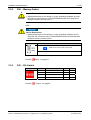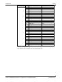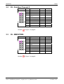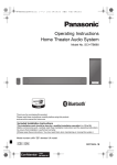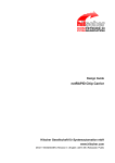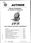
1
Hardware Description
NXHX 10-ETM
Software Development Board
Hilscher Gesellschaft für Systemautomation mbH
www.hilscher.com
DOC111103HW01EN | Revision 1 | English | 2011-12 | Released | Public
Introduction
2/29
Table of Contents
1
INTRODUCTION.........................................................................................................4
1.1
About this Manual .......................................................................................................4
1.1.1
1.1.2
1.2
Reference to Hardware...............................................................................................6
1.3
Documentation for NXHX 10-ETM..............................................................................6
1.4
Legal Notes.................................................................................................................7
1.4.1
1.4.2
1.4.3
1.4.4
1.4.5
2
4
2.1
Printed Circuit Board NXHX 10-ETM ..........................................................................9
2.2
Operating Elements ..................................................................................................10
T1 - Reset Button ...............................................................................................10
S20 – Memory-Switch ........................................................................................11
S30 – DIL-Switch................................................................................................11
J1 – Boot Jumper ...............................................................................................12
J50 – LEDs V50 and V51 ...................................................................................12
INTERFACES............................................................................................................13
3.1
X3 Host Interface Connector: ...................................................................................13
3.2
X5 - Fieldbus Channel 0 ...........................................................................................15
3.3
X6 - MMIO/PWM.......................................................................................................15
3.4
X9 - ETM Connector .................................................................................................16
3.5
X7 - UART0 ..............................................................................................................17
3.6
X4 - SD Card Slot .....................................................................................................17
3.7
X8 - USB Port for Development PC ..........................................................................18
3.8
X100 - Power Supply Jack........................................................................................18
3.9
X10 - AD-Converter Inputs .......................................................................................18
3.10
X50 - Ethernet Port ...................................................................................................19
3.11
X2 - netX USB Device Port.......................................................................................19
3.12
PAD Type Explanation for netX10 ............................................................................20
LEDS .........................................................................................................................21
4.1
5
Copyright ..............................................................................................................7
Important Notes ....................................................................................................7
Exclusion of Liability .............................................................................................8
Warranty ...............................................................................................................8
Export Regulations ...............................................................................................8
HARDWARE AND MECHANICS ................................................................................9
2.2.1
2.2.2
2.2.3
2.2.4
2.2.5
3
List of Revisions ...................................................................................................4
Conventions in this Manual ..................................................................................5
LED V1 SYS .............................................................................................................21
USING EXTERNAL DEBUGGERS ...........................................................................22
NXHX 10-ETM | Software Development Board
DOC111103HW01EN | Revision 1 | English | 2011-12 | Released | Public
© Hilscher, 2011
Introduction
6
3/29
ACCESSORIES ........................................................................................................23
6.1
Fieldbus Adapters.....................................................................................................23
6.1.1
6.1.2
6.1.3
6.1.4
6.1.5
7
6.2
NXAC-Power ............................................................................................................25
6.3
NXAC-JTAG-ETM.....................................................................................................25
TECHNICAL DATA ...................................................................................................26
7.1
8
NXHX-DP ...........................................................................................................24
NXHX-CO ...........................................................................................................24
NXHX-DN ...........................................................................................................24
NXHX-RS ...........................................................................................................24
NXHX-CC ...........................................................................................................24
NXHX 10-ETM ..........................................................................................................26
APPENDIX ................................................................................................................27
8.1
List of Figures ...........................................................................................................27
8.2
List of Tables ............................................................................................................27
8.3
Glossary....................................................................................................................28
8.4
Contacts....................................................................................................................29
NXHX 10-ETM | Software Development Board
DOC111103HW01EN | Revision 1 | English | 2011-12 | Released | Public
© Hilscher, 2011
Introduction
1
4/29
Introduction
1.1
About this Manual
This manual describes the NXHX 10-ETM evaluation board.
The NXHX 10-ETM is a development board for software development for
netX 10.
1.1.1
List of Revisions
Index
Date
Chapter
Revision
1
2011-12-05
All
Created
Table 1: List of Revisions
NXHX 10-ETM | Software Development Board
DOC111103HW01EN | Revision 1 | English | 2011-12 | Released | Public
© Hilscher, 2011
Introduction
1.1.2
5/29
Conventions in this Manual
Operation instructions, a result of an operation step or notes are marked as
follows:
Operation Instructions:
! <instruction>
Or
1. <instruction>
2. <instruction>
Results:
" <result>
Notes:
Important: <important note>
Note: <note>
<note, were to find further information>
Positions in Figures
,
,
... or
,
,
... or
,
,
... refer to the
The Positions
figure used in that section. If the numbers reference to a section outside the
current section then a cross reference to that section and figure is indicated.
NXHX 10-ETM | Software Development Board
DOC111103HW01EN | Revision 1 | English | 2011-12 | Released | Public
© Hilscher, 2011
Introduction
1.2
6/29
Reference to Hardware
Hardware
Hardware
Revision
Part Number
NXHX 10-ETM
1
7753.200
Table 2: Reference to Hardware
1.3
Documentation for NXHX 10-ETM
The following documentation overview gives information, for which items
you can find further information in which manual.
Manual
Contents
Technical Reference netX 10
Guide
Chip description
Document Name
netX10_Technical_Reference_Guide_09.pdf
Table 3: Additional Documentation
NXHX 10-ETM | Software Development Board
DOC111103HW01EN | Revision 1 | English | 2011-12 | Released | Public
© Hilscher, 2011
Introduction
1.4
1.4.1
7/29
Legal Notes
Copyright
© Hilscher, 2011, Hilscher Gesellschaft für Systemautomation mbH
All rights reserved.
The images, photographs and texts in the accompanying material (user
manual, accompanying texts, documentation, etc.) are protected by German and international copyright law as well as international trade and protection provisions. You are not authorized to duplicate these in whole or in
part using technical or mechanical methods (printing, photocopying or other
methods), to manipulate or transfer using electronic systems without prior
written consent. You are not permitted to make changes to copyright notices, markings, trademarks or ownership declarations. The included diagrams do not take the patent situation into account. The company names
and product descriptions included in this document may be trademarks or
brands of the respective owners and may be trademarked or patented. Any
form of further use requires the explicit consent of the respective rights
owner.
1.4.2
Important Notes
The user manual, accompanying texts and the documentation were created
for the use of the products by qualified experts, however, errors cannot be
ruled out. For this reason, no guarantee can be made and neither juristic
responsibility for erroneous information nor any liability can be assumed.
Descriptions, accompanying texts and documentation included in the user
manual do not present a guarantee nor any information about proper use
as stipulated in the contract or a warranted feature. It cannot be ruled out
that the user manual, the accompanying texts and the documentation do
not correspond exactly to the described features, standards or other data of
the delivered product. No warranty or guarantee regarding the correctness
or accuracy of the information is assumed.
We reserve the right to change our products and their specification as well
as related user manuals, accompanying texts and documentation at all
times and without advance notice, without obligation to report the change.
Changes will be included in future manuals and do not constitute any obligations. There is no entitlement to revisions of delivered documents. The
manual delivered with the product applies.
Hilscher Gesellschaft für Systemautomation mbH is not liable under any
circumstances for direct, indirect, incidental or follow-on damage or loss of
earnings resulting from the use of the information contained in this publication.
NXHX 10-ETM | Software Development Board
DOC111103HW01EN | Revision 1 | English | 2011-12 | Released | Public
© Hilscher, 2011
Introduction
1.4.3
8/29
Exclusion of Liability
The delivered product (including the technical data) is subject to export or
import laws as well as the associated regulations of different counters, in
particular those of Germany and the USA. The software may not be exported to countries where this is prohibited by the United States Export
Administration Act and its additional provisions. You are obligated to comply with the regulations at your personal responsibility. We wish to inform
you that you may require permission from state authorities to export, reexport or import the product.
1.4.4
Warranty
Although the hardware and software was developed with utmost care and
tested intensively, Hilscher Gesellschaft für Systemautomation mbH does
not guarantee its suitability for any purpose not confirmed in writing. It cannot be guaranteed that the hardware and software will meet your requirements, that the use of the software operates without interruption and that
the software is free of errors. No guarantee is made regarding infringements, violations of patents, rights of ownership or the freedom from interference by third parties. No additional guarantees or assurances are made
regarding marketability, freedom of defect of title, integration or usability for
certain purposes unless they are required in accordance with the law and
cannot be limited. Warranty claims are limited to the right to claim rectification.
1.4.5
Export Regulations
The delivered product (including the technical data) is subject to export or
import laws as well as the associated regulations of different counters, in
particular those of Germany and the USA. The software may not be exported to countries where this is prohibited by the United States Export
Administration Act and its additional provisions. You are obligated to comply with the regulations at your personal responsibility. We wish to inform
you that you may require permission from state authorities to export, reexport or import the product.
NXHX 10-ETM | Software Development Board
DOC111103HW01EN | Revision 1 | English | 2011-12 | Released | Public
© Hilscher, 2011
Hardware and Mechanics
2
2.1
9/29
Hardware and Mechanics
Printed Circuit Board NXHX 10-ETM
Figure 1: NXHX 10-ETM Printed Circuit Board
Number
Name
1
2
3
X6
4
V50
COM0
Section 4 / Page 21
5
V51
COM1
Section 4 / Page 21
6
J50
Description
Details
X3
Dual port Memory Interface
Section 3.1 / Page 13
X5
Fieldbus physical layer channel 0
Section 3.2 / Page 15
Section 3.3 / Page 15
Section 2.2.5 / Page 12
7
X9
ETM Connector
Section 3.4 / Page 16
8
X7
UART0 RS-232 module
Section 3.5 / Page 17
10
V15
Section 4 / Page 21
11
V14
Section 4 / Page 21
12
V13
Section 4 / Page 21
13
V12
Section 4 / Page 21
14
X4
SD Card Slot
Section 3.6 / Page 17
15
X8
USB Port for Development PC
Section 3.7 / Page 18
16
X100
Power Supply Jack, 24 V Power
connection.
Section 3.8 / Page 18
Mounting hole for RS-232 module.
Section 6.1 / Page 23
17
NXHX 10-ETM | Software Development Board
DOC111103HW01EN | Revision 1 | English | 2011-12 | Released | Public
© Hilscher, 2011
Hardware and Mechanics
Number
10/29
Name
Description
Details
18
S20
Section 2.2.2 / Page 11
19
X10
Section 3.9 / Page 17
20
V20
Memory Switch
Section 4 / Page 21
21
X50
netX Ethernet Port
Section 3.10 / Page 19
22
J1
Boot mode configuration
Section 2.2.4 / Page 12
23
X2
USB
Section 3.11 / Page 19
Mounting hole for fieldbus module.
Section 6.1 / Page 23
24
25
T1
Reset
Section 2.2.1 / Page 10
26
V1
SYS-LED
Section 4.1 / Page 21
Table 4: Designation in Device Drawing of NXHX 10-ETM
2.2
2.2.1
Operating Elements
T1 - Reset Button
T1
Function
A reset is done, when pushing the button.
Table 5: Reset Button T1
Number
in Figure 1 on page 9.
NXHX 10-ETM | Software Development Board
DOC111103HW01EN | Revision 1 | English | 2011-12 | Released | Public
© Hilscher, 2011
Hardware and Mechanics
2.2.2
11/29
S20 – Memory-Switch
Device Destruction!
NOTICE
# Hardware demage on the board or on the accessing hardware is possible with the concurrent use of Flash/SDRAM access of the board and
dual-port memory access via X3.
USA:
Device Destruction!
# Hardware demage on the board or on the accessing hardware is possible with the concurrent use of Flash/SDRAM access of the board and
dual-port memory access via X3.
S20
Function
MEM -> Flash/SDRAM is used , V20 is yellow on.
DPM access via X3 must not be used!
DPM -> Dual-port memory access via X3 is possible.
Table 6: S20 - Memory-Switch
Number
2.2.3
Figure 1 on page 9.
S30 – DIL-Switch
S30
Switch
netX 10 Signal
// to
Pin
1
MMIO04
X6
1
2
MMIO05
X6
2
3
MMIO06
X6
3
4
MMIO07
X6
4
Table 7: S30 – DIL-Switch
Number
in Figure 1 on page 9.
NXHX 10-ETM | Software Development Board
DOC111103HW01EN | Revision 1 | English | 2011-12 | Released | Public
© Hilscher, 2011
Hardware and Mechanics
2.2.4
12/29
J1 – Boot Jumper
J1
Boot Mode
Serial, USB or UART
Dual-port memory
Extension Bus
Table 8: J1 – Boot Jumper
Number
2.2.5
in Figure 1 on page 9.
J50 – LEDs V50 and V51
J50
Function
Jumper shall not be set if fieldbus modules on X5 are used. Otherwise
the signaling is misleading.
Connects the diodes V50 and V51 to +3V3.
Allows the signaling of Real-time Ethernet protocols at V50 and V51.
Table 9: J50 - LEDs V50 and V51
Number
in Figure 1 on page 9.
NXHX 10-ETM | Software Development Board
DOC111103HW01EN | Revision 1 | English | 2011-12 | Released | Public
© Hilscher, 2011
Interfaces
3
3.1
13/29
Interfaces
X3 Host Interface Connector:
Number
X3
in Figure 1: NXHX 10-ETM Printed Circuit Board
Pin
DPM
1
+3,3V
2
GND
PAD Typ
3
4
5
GND
6
7
RSTINn
8
9
10
11
DPM_DIRQ
IOU6
12
DPM_RDY
IOU6
13
GND
14
DPM_RDn
IOU6
DPM_WRn
IOU6
19
DPM_BHEn / DPM_BE1n
IOU6
20
GND
15
16
17
18
21
22
23
24
DPM_CSn
25
GND
26
DPM_A23
IOD6
27
DPM_A22
IOD6
28
DPM_A21
IOD6
29
DPM_A20
IOD6
30
DPM_A19
IOD6
31
DPM_A18
IOD6
32
DPM_A17
IOD6
33
GND
34
DPM_A15
IOD6
35
DPM_A14
IOD6
36
DPM_A13
IOD6
37
DPM_A12
IOD6
38
DPM_A11
IOD6
39
DPM_A10
IOD6
40
DPM_A9
IOD6
41
DPM_A8
IOD6
NXHX 10-ETM | Software Development Board
DOC111103HW01EN | Revision 1 | English | 2011-12 | Released | Public
IOU6
© Hilscher, 2011
Interfaces
14/29
X3
Pin
DPM
PAD Typ
42
DPM_A7
IOD6
43
DPM_A6
IOD6
44
DPM_A5
IOD6
45
DPM_A4
IOD6
46
DPM_A3
IOD6
47
DPM_A2
IOD6
48
DPM_A1
IOD6
49
DPM_A0
IOD6
50
GND
51
DPM_D15
IOD6
52
DPM_D14
IOD6
53
DPM_D13
IOD6
54
DPM_D12
IOD6
55
DPM_D11
IOD6
56
DPM_D10
IOD6
57
DPM_D9
IOD6
58
DPM_D8
IOD6
59
DPM_D7
IOD6
60
DPM_D6
IOD6
61
DPM_D5
IOD6
62
DPM_D4
IOD6
63
DPM_D3
IOD6
64
DPM_D2
IOD6
65
DPM_D1
IOD6
66
DPM_D0
IOD6
67
+3,3V
68
DPM_ A16
Table 10: Pin Assignment X3
The NXPCA-PCI Adapter can be connected at X3.
NXHX 10-ETM | Software Development Board
DOC111103HW01EN | Revision 1 | English | 2011-12 | Released | Public
© Hilscher, 2011
Interfaces
3.2
15/29
X5 - Fieldbus Channel 0
X5
Pin
Signal-Name
// to
1
XM_TX / MMIO01
V50 red
2
XM_AX / MMIO00
V50 green
3
XM_IO0 / MMIO03
V51 red
4
XM_ECLK/IO /
MMIO02
V51 green
PAD Typ
5
GND
6
+3V3
7
MMIO18
IOUS6
8
MMIO19
IOUS6
9
AIF_RESn
10
-
Table 11: Pin Assignment X5
Number
3.3
in Figure 1 on page 9.
X6 - MMIO/PWM
X6
Pin
Signal-Name
// to
PAD Typ
1
MMIO04
S30,1
IODS6
2
MMIO05
S30,2
IODS6
3
MMIO06
S30,3
IODS6
4
MMIO07
S30,4
IODS6
5
+ 3V3
6
GND
7
MMIO08
V12 LED
IODS6
8
MMIO09
V13 LED
IODS6
9
MMIO10
V14 LED
IOUS6
10
MMIO11
V15 LED
IOUS6
Table 12: Pin Assignment X6
Number
in Figure 1 on page 9.
NXHX 10-ETM | Software Development Board
DOC111103HW01EN | Revision 1 | English | 2011-12 | Released | Public
© Hilscher, 2011
Interfaces
3.4
16/29
X9 - ETM Connector
Note: Read and follow the note in section Using external Debuggers on
page 22 when using connector X9.
Number
X9
in Figure 1 on page 9.
Pin
Signal Name
ETM9
1
-
2
-
3
-
4
-
5
GND
6
MEM_A14
TRACECLK
7
MEM_A13
DBGRQ
8
MEM_A16
9
PORn
10
-
11
JT_TDO
12
+3V3
13
-
14
+3V3
15
JT_TCK
16
MEM_D7
TRACEPKT7
17
JT_TMS
TMS
18
MEM_D6
TRACEPKT6
SRSTN
TDO
TCK
19
JT_TDI
TDI
20
MEM_D5
TRACEPKT5
21
JT_TRSTN
TRSTN
22
MEM_D4
TRACEPKT4
23
MEM_D15
TRACEPKT15
24
MEM_A12
TRACEPKT3
25
MEM_D14
TRACEPKT14
26
MEM_A12
TRACEPKT2
27
MEM_D13
TRACEPKT13
28
MEM_A10
TRACEPKT1
29
MEM_D12
TRACEPKT12
30
MEM_A9
TRACEPKT0
31
MEM_D3
TRACEPKT11
32
MEM_A15
TRACESYNC
33
MEM_D2
TRACEPKT10
34
MEM_A8
PIPESTAT2
35
MEM_D1
TRACEPKT9
36
MEM_A7
PIPESTAT1
37
MEM_D0
TRACEPKT8
38
MEM_A6
PIPESTAT0
39
GND
40
GND
NXHX 10-ETM | Software Development Board
DOC111103HW01EN | Revision 1 | English | 2011-12 | Released | Public
© Hilscher, 2011
Interfaces
17/29
X9
Pin
Signal Name
41
GND
42
GND
43
GND
ETM9
Table 13: X9 - ETM, MICTOR Vertical Connector
3.5
X7 - UART0
X7
Pin
Signal-Name
PAD Typ
1
MMIO21 (TXD0)
IOUS6 (5k pu)
2
MMIO20 (RXD0)
IOUS6 (5k pu)
3
MMIO13 (RTS0)
IOUS6
4
MMIO12 (CTS0)
IOUS6
5
GND
6
+3V3
7
-
8
-
9
-
10
MMIO14
IOUS6
Table 14: Pin Assignment X6
Number
3.6
in Figure 1 on page 9.
X4 - SD Card Slot
X4
Pin
Signal-Name
PAD Typ
1
SPI_CSTn
IOUS6
2
SPII_MOSI
IOD6
3
GND
4
+3V3
5
SPI_CLK
6
GND
7
SPI_MISO
8
-
9
-
10
-
11
+3V3
12
MMC_INS
IOD6
IOD6
IOUS6
Table 15: X4 SD Card Slot
Number
in Figure 1 on page 9.
Note: The maximum size of the SD or MMC card is 4 GB. The card has
to be FAT 16 formatted. The card has to support the SPI legacy
mode.
NXHX 10-ETM | Software Development Board
DOC111103HW01EN | Revision 1 | English | 2011-12 | Released | Public
© Hilscher, 2011
Interfaces
3.7
18/29
X8 - USB Port for Development PC
X8
Pin
Signal-Name
1
VUSB
2
USBDM
3
USBDP
4
GND
Table 16: Pin Assignment X6
Number
in Figure 1 on page 9.
Note: Read and follow the note in section Using external Debuggers on
page 22 when using connector X8.
3.8
X100 - Power Supply Jack
The NXHX 10-ETM development board has to be supplied by DC. VIN is
from 18 V to 30 V. The typical supply voltage is 24 V. Power consumption
is approx. 2.6 W.
Number
Pin
Description
1
GND Ground
2
VIN 18 - 30 V DC
in Figure 1 on page 9.
The connection for the power supply is suitable for the power supply
NXAC-Power.
3.9
X10 - AD-Converter Inputs
X10
Pin
Signal-Name
Description
1
AD0_IN0
AD-Converter 0 Input 0
2
AD0_IN1
AD-Converter 0 Input 1
3
AD0_IN2
AD-Converter 0 Input 2
4
AD0_IN3
AD-Converter 0 Input 3
5
GND
Ground
6
AD_VREFP
+3V3, reference voltage
7
AD1_IN0
AD-Converter 1 Input 0
8
AD1_IN1
AD-Converter 1 Input 1
9
AD1_IN2
AD-Converter 1 Input 2
10
AD1_IN3
AD-Converter 1 Input 3
Table 17: Pin Assignment X6
Number
in Figure 1 on page 9.
NXHX 10-ETM | Software Development Board
DOC111103HW01EN | Revision 1 | English | 2011-12 | Released | Public
© Hilscher, 2011
Interfaces
19/29
3.10 X50 - Ethernet Port
Ethernet on RJ45 Pin Assignment
Ethernet
RJ45 socket, female
Pin
Signal
Description
1
TX+
Transmit data positive
2
TX–
Transmit data negative
3
RX+
Receive data positive
4
Term 1
5
Term 1
Connected and terminated to PE via RC
combination*
6
RX–
Receive data negative
7
Term 2
8
Term 2
Connected and terminated to PE via RC
combination*
* Bob Smith Termination
Table 18: Ethernet RJ45 Pin Assignment
Number
in Figure 1 on page 9.
3.11 X2 - netX USB Device Port
USB Socket
Pin
Signal
Description
D-
Data -
3
D+
Data +
4
ID
5
GND
1
2
Ground
Table 19: Pin Assignment Mini-B USB Connector (5-pin)
Number
in Figure 1 on page 9.
NXHX 10-ETM | Software Development Board
DOC111103HW01EN | Revision 1 | English | 2011-12 | Released | Public
© Hilscher, 2011
Interfaces
20/29
3.12 PAD Type Explanation for netX10
Symbol
Description
I
Input
O
Output
Z
Output is tristateable or open drain
S
Input provides Schmitt trigger
U
Internal pull-up 50 k (MMIO20-23: pull-up 5k)
D
Internal pull-down 50 k
6
Output buffer can source / sink 6 mA
9
Output buffer can source / sink 9 mA
XTAL
Crystal input or output
USB
USB pad
PHY
PHY pad
ANA
Analog pin
PWR
1.5 V (Core) or 3.3 V (I/O)
GND
Digital Ground (0 V)
APWR
Analog power (1.5V or 3.3V)
AGND
Analog ground (0 V)
Table 20: PAD Type Explanation
NXHX 10-ETM | Software Development Board
DOC111103HW01EN | Revision 1 | English | 2011-12 | Released | Public
© Hilscher, 2011
LEDs
4
21/29
LEDs
LED Naming
in the Device
Drawing
LED Name
V1
SYS
System Status
(yellow /
green)
Signal Name
(green)
RDY
(yellow)
RUN
V50 (
COM0
(green)
MMIO00
(red / green)
Communication
status
(red)
MMIO01
V51
COM1
(green)
MMIO02
(red / green)
(red)
MMIO03
V12
(yellow)
(yellow)
MMIO08
V13
(yellow)
(yellow)
MMIO09
V14
(yellow)
(yellow)
MMIO10
V15
(yellow)
(yellow)
MMIO11
V20
(yellow)
4.1
Color
Signals position
MEM of S20
Do not use X3 at the same
time!
LED V1 SYS
The following table describes the meaning of the system LED.
LED
Color
SYS
Duo LED yellow/green
State
Meaning
On
Operating System running
Blinking
green/yellow
Bootloader is waiting for firmware
Blinking
Heavy system error: PLC in stop.
static
Bootloader is waiting for software
Off
Power supply for the device is missing or hardware defect.
(green)
(green/yellow)
(yellow)
(yellow)
-
Table 21: System LED
Number
in Figure 1 on page 9.
NXHX 10-ETM | Software Development Board
DOC111103HW01EN | Revision 1 | English | 2011-12 | Released | Public
© Hilscher, 2011
Using external Debuggers
5
22/29
Using external Debuggers
Instead of using the onboard debugger of the NXHX 10-ETM along with the
HiTOP software, an external debugger with either ETM or JTAG interface
can be connected to the NXHX 10-ETM. If an ETM debugger is used, simply connect the debugger to the ETM connector (X9) of the NXHX 10-ETM.
If a JTAG debugger is used, connect the ETM-to-JTAG adapter (NXACJTAG-ETM) that came with your NXHX 10-ETM board to the ETM connector and then connect your JTAG debugger to the 20 pin shrouded header
as shown below.
Hardware Damage!
Only one debugger, either the onboard unit or an external debugger may
be active at a time, otherwise the debugger signals may drive against
each other, which may result in damage of the onboard debugger and / or
the external debugger!
When using an external debugger, the USB port for the Development PC
(X8) must not be connected! Further, any adapter board (e.g. RS-232) must
be removed from X7.
When using the onboard debugger, an external debugger must not be connected to the ETM connector (X9)!
Figure 2: NXHX 10-ETM with JTAG-ETM Adapter
NXHX 10-ETM | Software Development Board
DOC111103HW01EN | Revision 1 | English | 2011-12 | Released | Public
© Hilscher, 2011
Accessories
6
6.1
23/29
Accessories
Fieldbus Adapters
Figure 3: NXHX 10-ETM with possible Field-Bus-Modules
Fieldbus Interface with Duo Status LED
(Ready / Error) for NXHX Boards.
Pin
Signal
Pin
Signal
1
XMAC TX
6
+3,3V
2
XMAC RX
7
PIO 4
3
XMAC IO 0
8
PIO 5
4
XMAC IO 1
9
RSTOUT
5
GND
10
n.c.
Connector to NXHX Board.
Figure 4: Fieldbus Connector (Dimensions in mm)
NXHX 10-ETM | Software Development Board
DOC111103HW01EN | Revision 1 | English | 2011-12 | Released | Public
© Hilscher, 2011
Accessories
6.1.1
24/29
NXHX-DP
Fieldbus Interface PROFIBUS (RS-485)
Connector: D-Sub DE-9 female
Interface not isolated
Order Number: 7923.410
6.1.2
Signal
Pin
Signal
1
n.c.
6
n.c.
2
n.c.
7
n.c.
3
TXD/RXD-P
8
TXD/RXD-N
4
n.c.
9
n.c.
5
GND
Pin
Signal
Pin
Signal
1
n.c.
6
n.c.
2
CAN-L
7
CAN-H
3
DGND
8
nc.
4
n.c.
9
n.c.
5
n.c.
Pin
Signal
1
DGND
2
CAN-L
NXHX-CO
Fieldbus Interface CAN
Connector: D-Sub DE-9 male
Interface not isolated
Order Number: 7923.500
6.1.3
Pin
NXHX-DN
Fieldbus Interface DeviceNet
Connector: Combicon MSTBA 2,5
Interface not isolated
3
n.c.
Order Number: 7923.510
4
CAN-H
5
DN V+
Pin
Signal
Pin
Signal
1
n.c.
6
n.c.
6.1.4
NXHX-RS
Interface RS232
Connector: D-Sub DE-9 male
2
RXD
7
RTS
Interface not isolated
3
TXD
8
CTS
Order Number: 7923.010
4
DTR
9
n.c.
5
GND
Pin
Signal
1
DA
2
DB
3
DG
6.1.5
NXHX-CC
Fieldbus Interface CC-Link:
Connector: Combicon MSTBA 2,5
Interface not isolated
Order Number: 7923.740
4
SLD
5
FG
NXHX 10-ETM | Software Development Board
DOC111103HW01EN | Revision 1 | English | 2011-12 | Released | Public
© Hilscher, 2011
Accessories
6.2
25/29
NXAC-Power
Power Supply for NXHX Boards
Technical Data:
Input:
100-240V ~0,4A (47-63Hz)
Output:
24V / 0,625mA
Cable:
1,8 m
Order Number: 7930.000
6.3
with barrel connector
sizes in mm
NXAC-JTAG-ETM
ETM-to-JTAG adapter
Order Number: 2400.200
NXHX 10-ETM | Software Development Board
DOC111103HW01EN | Revision 1 | English | 2011-12 | Released | Public
© Hilscher, 2011
Technical Data
7
7.1
26/29
Technical Data
NXHX 10-ETM
Item
NXHX 10-ETM
Supply Voltage
24V DC
Processor
netX 10
Memory
Working memory: 256 KByte SDRAM
16 MByte serial Flash
LED
SYS, V1; COM0, V50; COM1, V51; V20; V12;V13;V14;V15
Operating Elements
Reset push-button, Memory-Switch
Memory Card
SD/MMC max. 4GB, FAT16 formatted
USB Mini-B
configuration / diagnostic
USB Typ B
Development PC connection
RJ45
Ethernet
Dimensions (L x W x D)
100 x 69 x 20 mm
Operating Temperature
0 … 55 °C
Table 22: Technical Data NXHX 10-ETM
Input / Output
Min.
Analog Inut AI
Typ.
Max.
Unit
0…
AD_VREFP
V
ADC_VREFP
3,0
3,3
3,6
V
ADC_IVDDIO
0,3
0,6
1,2
mA
VIH
2,0
3,3
3,6
V
VIL
0
0,8
V
10
µA
Binary Input DI
Ili
Binary Output DO
VOH
Notice! Outputs are not overload protected.
2,4
IOH
3,3-0,1
V
18
mA
Table 23: Technical Data NXHX 10-ETM, Local I/O Signals at Connector X1
Technical data of the input and output are described in detail in the
„netX10 Technical Data Reference Guide“.
NXHX 10-ETM | Software Development Board
DOC111103HW01EN | Revision 1 | English | 2011-12 | Released | Public
© Hilscher, 2011
Appendix
8
8.1
Appendix
List of Figures
Figure 1: NXHX 10-ETM Printed Circuit Board
Figure 2: NXHX 10-ETM with JTAG-ETM Adapter
Figure 3: NXHX 10-ETM with possible Field-Bus-Modules
Figure 4: Fieldbus Connector (Dimensions in mm)
8.2
27/29
9
22
23
23
List of Tables
Table 1: List of Revisions
Table 2: Reference to Hardware
Table 3: Additional Documentation
Table 4: Designation in Device Drawing of NXHX 10-ETM
Table 5: Reset Button T1
Table 6: S20 - Memory-Switch
Table 7: S30 – DIL-Switch
Table 8: J1 – Boot Jumper
Table 9: J50 - LEDs V50 and V51
Table 10: Pin Assignment X3
Table 11: Pin Assignment X5
Table 12: Pin Assignment X6
Table 13: X9 - ETM, MICTOR Vertical Connector
Table 14: Pin Assignment X6
Table 15: X4 SD Card Slot
Table 16: Pin Assignment X6
Table 17: Pin Assignment X6
Table 18: Ethernet RJ45 Pin Assignment
Table 19: Pin Assignment Mini-B USB Connector (5-pin)
Table 20: PAD Type Explanation
Table 21: System LED
Table 22: Technical Data NXHX 10-ETM
Table 23: Technical Data NXHX 10-ETM, Local I/O Signals at Connector X1
NXHX 10-ETM | Software Development Board
DOC111103HW01EN | Revision 1 | English | 2011-12 | Released | Public
4
6
6
10
10
11
11
12
12
14
15
15
17
17
17
18
18
19
19
20
21
26
26
© Hilscher, 2011
Appendix
8.3
28/29
Glossary
DP
Decentral periphery
DPM
Dual-port memory
netX
networX on chip, next generation of communication controllers
NXHX 10-ETM | Software Development Board
DOC111103HW01EN | Revision 1 | English | 2011-12 | Released | Public
© Hilscher, 2011
Appendix
8.4
29/29
Contacts
Headquarters
Germany
Hilscher Gesellschaft für
Systemautomation mbH
Rheinstrasse 15
65795 Hattersheim
Phone: +49 (0) 6190 9907-0
Fax: +49 (0) 6190 9907-50
E-Mail: [email protected]
Support
Phone: +49 (0) 6190 9907-99
E-Mail: [email protected]
Subsidiaries
China
Japan
Hilscher Systemautomation (Shanghai) Co. Ltd.
200010 Shanghai
Phone: +86 (0) 21-6355-5161
E-Mail: [email protected]
Hilscher Japan KK
Tokyo, 160-0022
Phone: +81 (0) 3-5362-0521
E-Mail: [email protected]
Support
Support
Phone: +86 (0) 21-6355-5161
E-Mail: [email protected]
Phone: +81 (0) 3-5362-0521
E-Mail: [email protected]
France
Korea
Hilscher France S.a.r.l.
69500 Bron
Phone: +33 (0) 4 72 37 98 40
E-Mail: [email protected]
Hilscher Korea Inc.
Suwon, 443-734
Phone: +82 (0) 31-695-5515
E-Mail: [email protected]
Support
Phone: +33 (0) 4 72 37 98 40
E-Mail: [email protected]
India
Hilscher India Pvt. Ltd.
New Delhi - 110 025
Phone: +91 11 40515640
E-Mail: [email protected]
Switzerland
Hilscher Swiss GmbH
4500 Solothurn
Phone: +41 (0) 32 623 6633
E-Mail: [email protected]
Support
Phone: +49 (0) 6190 9907-99
E-Mail: [email protected]
Italy
USA
Hilscher Italia srl
20090 Vimodrone (MI)
Phone: +39 02 25007068
E-Mail: [email protected]
Hilscher North America, Inc.
Lisle, IL 60532
Phone: +1 630-505-5301
E-Mail: [email protected]
Support
Support
Phone: +39 02 25007068
E-Mail: [email protected]
Phone: +1 630-505-5301
E-Mail: [email protected]
NXHX 10-ETM | Software Development Board
DOC111103HW01EN | Revision 1 | English | 2011-12 | Released | Public
© Hilscher, 2011