1
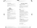
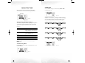
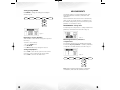
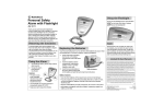
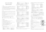
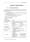
SMART TWEEZERS Model ST-1 User’s Manual Version 1.0 Patent Pending Notice The contents of this document is believed to be accurate, but is not guaranteed by Excelta Corporation. The information contained within may be changed at any time and Excelta Corporation and its distri butors do not assume any responsibility for omissions or errors in this document. SAFETY INFORMATION Warnings • Inspect the Smart Tweezers case before using. L ook for cracks and any damage. Do not use the device if it appears to be damaged. • Do not use the device if it operates abnormally. • Do not attempt to measure any components in-circuit when your circuit is under the power. Cautions To avoid possible damage to Smart Tweezers or to the equipment under test, follow these guidelines: • Disconnect circuit power and discharge all high-voltage capacitors before testing resistance, inductance, or capacitance. • Do not measure voltages more than 800 mV when in automatic mode. • Use proper terminals and functions for your measure ments. • Use the correct batteries to power Smart Tweezers. TABLE OF CONTENTS NOTICE . . . . . . . . . . . . . . . . . . . . . . . . . . . . . . . . . . . 2 SAFETY INFORMATION . . . . . . . . . . . . . . . . . . . . . . Warnings . . . . . . . . . . . . . . . . . . . . . . . . . . . . . . . . . . Cautions . . . . . . . . . . . . . . . . . . . . . . . . . . . . . . . . . . Distributors . . . . . . . . . . . . . . . . . . . . . . . . . . . . . . . . Table of Contents . . . . . . . . . . . . . . . . . . . . . . . . . . . . Overview . . . . . . . . . . . . . . . . . . . . . . . . . . . . . . . . . . 2 2 2 2 3 4 QUICK REFERENCE . . . . . . . . . . . . . . . . . . . . . . . . . . Display Area . . . . . . . . . . . . . . . . . . . . . . . . . . . . . . . . Primary Display . . . . . . . . . . . . . . . . . . . . . . . . . . . . . Secondary Display . . . . . . . . . . . . . . . . . . . . . . . . . . . The Jog Dial Button . . . . . . . . . . . . . . . . . . . . . . . . . . Reset Button . . . . . . . . . . . . . . . . . . . . . . . . . . . . . . . Virtual Ground . . . . . . . . . . . . . . . . . . . . . . . . . . . . . . Slide Switch . . . . . . . . . . . . . . . . . . . . . . . . . . . . . . . . 5 5 5 5 6 6 6 6 USING THE SMART TWEEZER . . . . . . . . . . . . . . . . . Turning Smart Tweezers ON . . . . . . . . . . . . . . . . . . . . Automatic Power Off . . . . . . . . . . . . . . . . . . . . . . . . . Battery . . . . . . . . . . . . . . . . . . . . . . . . . . . . . . . . . . . . Low Battery Indication . . . . . . . . . . . . . . . . . . . . . . . . 7 7 7 7 7 MENU STRUCTURE . . . . . . . . . . . . . . . . . . . . . . . . . Changing from the Default Setting . . . . . . . . . . . . . . Returning to Factory Defaults . . . . . . . . . . . . . . . . . . . Saving Setup Options . . . . . . . . . . . . . . . . . . . . . . . . . 8 8 10 10 MEASUREMENTS . . . . . . . . . . . . . . . . . . . . . . . . . . . 11 MAINTENANCE . . . . . . . . . . . . . . . . . . . . . . . . . . . . . 14 General Maintenance . . . . . . . . . . . . . . . . . . . . . . . . . 14 Replacing the Batteries . . . . . . . . . . . . . . . . . . . . . . . . 14 TROUBLESHOOTING . . . . . . . . . . . . . . . . . . . . . . . . 14 www.mbr.ch 2 SPECIFICATIONS . . . . . . . . . . . . . . . . . . . . . . . . . . . . Basic Specifications . . . . . . . . . . . . . . . . . . . . . . . . . . . Detailed Accuracy Specifications . . . . . . . . . . . . . . . . . Resistance . . . . . . . . . . . . . . . . . . . . . . . . . . . . . . . . . Capacitance . . . . . . . . . . . . . . . . . . . . . . . . . . . . . . . . Inductance . . . . . . . . . . . . . . . . . . . . . . . . . . . . . . . . . Feature Summary . . . . . . . . . . . . . . . . . . . . . . . . . . . . 14 15 15 15 15 15 15 3 OVERVIEW QUICK REFERENCE Smart Tweezers is an R-L-C meter in a set of tweezers. Smart Tweezers is designed for production line compo nent evaluation, on board impedance testing, and SMD components sorting. With automatic recognition of measurement mode (R, L and C) Smart Tweezers is ideal for identifying surface mounted devices. Jog Dial Button Display Area Smart Tweezers has two display modes, Primary and Secondary. Secondary Display Reset Figure 2. Primary Display Slide switch for extended Voltage measurements Virtual Ground Connector Figure 1. Smart Tweezers has a unique mechanical and electronic design that incorporates a built-in direct precision SMD probe designed for component evaluation on the pro duction line, PCB debugging, component impedance testing and sorting SMD components. The integrated SMD probe and graphic display, combined with automatic recognition of measurement modes (R, C, and L) and the range of measurement, allows the opera tor focus on the component under test. As a result test ing, sorting and evaluation of components becomes more efficient and cost effective. Bar Graph Primary Display The Primary Display is located in the middle of the display and is the larger of the two displays available. It shows the present reading. For most functions the primary display shows 5 digits. If OUT OF RANGE is displayed an overload condition is present. Secondary Display The Secondary Display is located at the top of the display and is the smaller of the two displays. It shows the present reading of additional parameters, or measurement conditions when the primary display shows some other feature (e.g. L, C). When multiple features are present, secondary display shows one of the values. For example, ESR value can appear in the secondary display while capacitor value appears in the primary display. Bar Graph The bar graph provides an analog indication of the meas ured input and is located at the bottom of the display. 4 5 The Jog Dial Button USING SMART TWEEZERS The Jog Dial button (Figure. 3) is used to choose the selected function or to change a setting. Turning Smart Tweezers ON To change the menu displayed press and move the button left or right. To turn the Smart Tweezers ON, press the jog dial button to any position. To select or execute a function press the button down (Figure 3). The sign in the low left corner of the display indicates that device is ON and ready to perform measurements. A, R, L or C indicate auto, resistance, inductance and capacitance respectively. 10 kHz Figure 3. Figure 4. Reset Button The reset button resets the unit. This may need to be pressed after changing the batteries. Virtual Ground Use the Virtual Ground connector when performing in-circuit measurements to eliminate the influence of grounded components. Connect this point to the circuit Ground. Important: Do NOT use the virtual ground when the tested circuit is under power. Slide Switch The slide switch can optionally be used to measure DC voltage up to 8V by enabling a 1/10 voltage divider. Important: The slide switch should be turned off once the voltage measurement is completed. If it is not turned off incorrect results in automatic mode may occur. The slide switch is not an automatic control option. Automatic Power Off The unit will automatically power off, the display goes blank and the device goes into a “sleep” mode if no component has been touched or button pressed for approximately 30 seconds. You can set power off interval by change TIMEOUT setting in DISPLAY menu. Pressing the Jog Dial button turns Smart Tweezers back on and the device then returns to the display for the previously selected function. Automatic power off does not occur when the device is in VOLTAGE, TRACE or MENU mode. Battery Smart Tweezers uses three 1.5V alkaline or air zinc “button” type batteries, size 11.2 x 5.6mm (Type 357A or LR44). Low Battery Indication The Low Battery message and battery icon in the display is the notification that the batteries are low and should be replaced (Fig. 5). The warning appears when the batteries are about 90% depleted. The unit is still operational for a short time, however the batteries should be replaced as soon as possible. Figure 5. 6 7 MENU STRUCTURE From the main menu it is possible to set the Smart Tweezers back to their default setting (AUTOSET) or go to SYSTEM or MEASURE menus (Fig. 6). SOUND Menu Use the SOUND setting to turn the beeper ON or OFF as shown in Fig. 8. Actual Setting Figure 8. Figure 6. Selected Item DISPLAY orientation, contrast, timeout setting Use the DISPLAY setting to change the display orienta tion, the contrast and the timeout as shown in Fig. 9. Changing from the Default Setting The user can change the default operating configuration of Smart Tweezers by changing the options. All setup options affect general operations and are active in all functions. MAIN SYSTEM SOUND ON EXIT OFF MAIN SYSTEM DISPLAY LEFT EXIT Smart Tweezers factory setting Frequency: Measurement: Period: Sound: Display: Timeout: AUTO range Meter automatically selects frequency for the best accuracy. AUTO range Meter automatically selects R, C or L measurement. 1s OFF RIGHT 30 seconds RIGHT MAIN SYSTEM DISPLAY CONTR EXIT CONTRAST MAIN SYSTEM DISPLAY TIMEOUT EXIT TIMEOUT To enter SETUP mode turn on the device and go to MAIN menu. SYSTEM Setting Menu Use SYSTEM menu to set up system parameters for all functions (Fig. 7). Figure 9. Figure 7. 8 9 Setting testing PERIOD MEASUREMENTS Use PERIOD to change the reading period setting as shown in Fig. 10. MAIN SYSTEM PERIOD 2 SEC The default setting is to perform fully automatic auto range measurement for resistance, inductance and capacitance. EXIT 1 SEC 1/2 SEC 1/4 SEC Most measurement functions also have a manual mode, which can be selected by using the jog dial button. Use the manual setting when you need to measure a specific parameter or need better accuracy. MEASUREMENT setting menu To measure specific components or to change measurement parameters, use Measure menu as shown in (Fig. 11). Figure 10. Returning to Factory Defaults Smart Tweezers comes with the setup options preset at the factory. To return to these settings: 1. Go to the MAIN menu. 2. Set AUTOSET. 3. Set EXIT and all factory settings are restored. Figure 11. Measuring Resistance, Inductance or Capacitance For automatic measurement use AUTO setting (default). To measure only one parameter – resistance, inductance or capacitance set Smart Tweezers as shown in Fig. 12. Saving Setup Options Choose EXIT to save the last option from the current menu. This option is marked by the arrow symbol. Choose EXIT to exit from the main menu. Figure 12. MAIN MEASURE MODE AUTO EXIT R L C Note: When measuring small resistance, capacitance or inductance, make sure that terminals are clean. 10 11 Test Frequency Setting For automatic measurement use AUTO setting (default). Use fixed test frequency for specific measurements, such as very small or very large capacitance (less than 50pf or more than 100uF) or inductance. Use AUTO mode (default) to measure DC Voltage from 100uV to 800mV. Figure 15. Use TRACE mode if you want to see the oscilloscope like picture of Voltage as shown in (Fig. 16). Figure 13. To fix test frequency set Smart Tweezers as shown in Fig. 13. MAIN MEASURE FREQ AUTO To change speed turn jog dial button LEFT or RIGHT. To EXIT press the job dial button. EXIT 10 KHz Figure 16. 1 KHz Adjusting Voltage Offset 0.1 KHz To adjust voltage offset: Measuring Voltage Use AUTO mode (default) to measure DC Voltage from 100uV to 800mV (up to 8V with slide switch manual set ting). To measure voltages configure Smart Tweezers as shown in Fig. 14. 1. Connect the probes to each other and choose CALIBER mode. 2. Press EXIT to exit calibration mode. 3. Disconnect probes. Use BATTERY mode to measure current battery voltage. Press the jog dial button to exit. Figure 14. Figure 17. MAIN MEASURE VOLTAGE AUTO EXIT TRACE CALIBR BATTERY 12 13 MAINTENANCE General Maintenance Dirt or moisture in the terminals can affect measurement accuracy. Clean the terminals regularly. Do not use abra sives or solvents. To clean the terminals: 1. Turn the device off. 2. Shake out any dirt that may be on the terminals. 3. Soak a new swab with alcohol. Work the swab around each terminal. Replacing the Batteries Replace the batteries with three alkaline or air-zinc batteries (LR44 or 375A type). To replace the batteries: 1. Remove three screws with screwdriver TORX # 5 and lift the cover. 2. Replace the batteries follow the “+” and “–“ sign. 3. Secure the cover. 4. Reset the device. Troubleshooting If there appears to be a malfunction during the operation of the device, the following steps should be performed in order to isolate the cause of the problem: 1. Check the battery. 2. Review the operating instructions for possible mistakes in operating procedure. CAUTION: Except for replacing the battery, repair of the device should only be performed by an Authorized Service Center or by qualified device service personnel. SPECIFICATIONS Physical Specifications Operating Temperature: Storage Temperature: Relative Humidity: Altitude Operating: Storage: Battery Type: Battery Life: 14 0 °C to + 55 °C 40 °C to + 60 °C 0 % to 90 % (0 °C to 35 °C) 0 % to 70 % (35 °C to 55 °C) 0 – 2000 meters 10000 meters 1.5 V LR44 (357A) Alkaline or Air zinc 80 Hours typical with alkaline, 220 hours with air zinc battery Electromagnetic Compatibility (EMC): Size: Weight: Warranty: Susceptibility and Emission: FCC 15 part B 14.0 x 2.5 x 3.0 cm (3.94 x 0.9 x 1.5 in) 53 grams (0.11 lb) 1 year Basic Specifications Measured Parameters: Measuring Frequencies: Measurement rate: DC Voltage: Resistance: Resolution: Capacitance: Inductance: Battery life: C, L, R, ESR, Rs, Rp 100 Hz, 1 kHz, 10 kHz 1 time per second, default 0 to 800 mV (Up to 8 V with optional slide switch manual setting) 0.1 Ohm – 9 M Ohm 0.1 Ohm – 1 M Ohm 0.01 Ohm 10 pF to 499 mF 1 uH to 999 mH minimum 120 hrs (Air-Zinc batteries) Detailed Accuracy Specifications Accuracy is specified at 18 °C to 28 °C (64 °F to 82 °F), with relative humidity to 90 %. Resistance Range: 0.1 Ohm – 5 MOhm Accuracy: 1 % in range 0.1 R – 1 M 2 % in range 1 M – 5 M Resolution: 0.01 R in range 0 – 10 R Test Frequency: 1 kHz Capacitance Range: 10 pF – 499 uF Accuracy: 5 % in range 20 pF – 499 uF Resolution: 0.5 pF in range 1 pF – 100 pF Test Frequency: 1 kHz C > 1000 pF 10 kHz C < 1000 pF 100 Hz C > 1 uF Inductance Range: 1 uH – 1 H Accuracy: 10 % in range 1 uH – 10 uH 5 % in range 10 uH – 100 uH 5 % in range 100 uH – 1 H Resolution: 0.5 uH in range 1 uH – 100 uH Test Frequency: 10 kHz L < 1 uH 1 k Hz L > 1 uH 100 Hz L > 1 mH Feature Summary Graphics Displays. Analog Bar Graph. Fully automatic measurement of Inductance, Capacitance and Resistance. Auto range: Meter automatically selects best range. Trace Graph: Oscilloscope like display for voltage measurement. 15 LABELLING & VERIFICATION REQUIREMENTS This device complies with Part 15 of the FCC Rules. Operation is subject to the following two conditions: 1. this device may not cause harmful interference and 2. this device must accept any interference received, including interference that may cause undesired operation. 16